EP2014539B1 - Carrosserie de véhicule automobile dotée de longerons latéraux - Google Patents
Carrosserie de véhicule automobile dotée de longerons latéraux Download PDFInfo
- Publication number
- EP2014539B1 EP2014539B1 EP08009438A EP08009438A EP2014539B1 EP 2014539 B1 EP2014539 B1 EP 2014539B1 EP 08009438 A EP08009438 A EP 08009438A EP 08009438 A EP08009438 A EP 08009438A EP 2014539 B1 EP2014539 B1 EP 2014539B1
- Authority
- EP
- European Patent Office
- Prior art keywords
- sheet
- pillar
- sill
- metal outer
- outer part
- Prior art date
- Legal status (The legal status is an assumption and is not a legal conclusion. Google has not performed a legal analysis and makes no representation as to the accuracy of the status listed.)
- Expired - Fee Related
Links
Images


Classifications
-
- B—PERFORMING OPERATIONS; TRANSPORTING
- B62—LAND VEHICLES FOR TRAVELLING OTHERWISE THAN ON RAILS
- B62D—MOTOR VEHICLES; TRAILERS
- B62D21/00—Understructures, i.e. chassis frame on which a vehicle body may be mounted
- B62D21/15—Understructures, i.e. chassis frame on which a vehicle body may be mounted having impact absorbing means, e.g. a frame designed to permanently or temporarily change shape or dimension upon impact with another body
- B62D21/157—Understructures, i.e. chassis frame on which a vehicle body may be mounted having impact absorbing means, e.g. a frame designed to permanently or temporarily change shape or dimension upon impact with another body for side impacts
-
- B—PERFORMING OPERATIONS; TRANSPORTING
- B62—LAND VEHICLES FOR TRAVELLING OTHERWISE THAN ON RAILS
- B62D—MOTOR VEHICLES; TRAILERS
- B62D25/00—Superstructure or monocoque structure sub-units; Parts or details thereof not otherwise provided for
- B62D25/02—Side panels
-
- B—PERFORMING OPERATIONS; TRANSPORTING
- B62—LAND VEHICLES FOR TRAVELLING OTHERWISE THAN ON RAILS
- B62D—MOTOR VEHICLES; TRAILERS
- B62D25/00—Superstructure or monocoque structure sub-units; Parts or details thereof not otherwise provided for
- B62D25/02—Side panels
- B62D25/025—Side sills thereof
Definitions
- the invention relates to a motor vehicle body with a side sill.
- the sill of a motor vehicle is an essential support and support element of a support structure of a motor vehicle.
- the sill should represent a stable barrier in a side crash against a depression of the passenger compartment.
- the sill is provided with reinforcing elements in order to increase the rigidity of the sill.
- a door sill known with an outer shell and an inner shell and a web plate.
- the latter divides the formed in the manner of a hollow profile carrier door sill in a first hollow chamber and a second hollow chamber.
- a profile arrangement is provided, the essential elements of which are a longitudinally extending profile part and a spacer profile part. These form together with the web plate together a composite component and may optionally be connected to at least one of the two shells of the door sill.
- Both the profile part and the spacer profile part are hat-shaped or horn-like and have surface trained force application areas, which are either directly connected to the surrounded sheet metal shells or have these only a small distance.
- a side sill with a closed cross section is known, which is formed by a body side panel and a side sill plate. Within the closed cross-section are an outer side sill reinforcement and an inner side sill reinforcement.
- the JP 04 081371 A discloses a motor vehicle body with a side sill, which consists of a sheet metal inner part, a sheet metal outer part and an intermediate composed of the inner plate part and the sheet metal outer part arranged reinforcement part.
- a vertical flat wall reinforcing member is respectively firmly connected to the upper and lower ends of the inner plate part and the sheet metal outer part and divides the sill into an outer and an inner hollow chamber.
- impact elements are provided in two hollow chambers, which are fixed to the plate-shaped reinforcement member.
- the outer baffle extends over a substantial part of its height extent at a distance from the adjacent sheet metal outer part.
- the sill is formed by a sheet metal inner part, a sheet metal outer part and a profiled reinforcing part.
- the profiled reinforcing member extends over the entire height of the sill and is respectively connected to upper and lower parked flanges of the inner plate part and the sheet metal outer part.
- An impact element for transmitting lateral impact forces is provided between the profiled reinforcement part and the inner plate part, but not between the sheet outer part and the reinforcement part.
- the profiled reinforcing plate of the sill is also connected to the upper and lower parked flanges of the inner plate part and the sheet metal outer part and in the region of a bottom-side cross member between the reinforcing plate and the inner plate part of the sill, a baffle element for transmitting lateral impact forces.
- This baffle element is connected to the profiled reinforcing plate and extends at a distance to the inner plate part.
- the JP 01018784 A shows a sill of a motor vehicle body, wherein within the consisting of a sheet metal outer part and a sheet metal inner door sill an elongated stiffening tube is arranged, which is connected via local junction plates with the inner plate part and the sheet metal outer part.
- the DE102005038463 A shows a motor vehicle body with a side sill consisting of a metal inner part and a connected thereto, outwardly projecting sheet outer part and arranged between the inner plate part and the sheet metal outer reinforcement part.
- the upper and lower ends of the inner plate part are connected to the upper and lower ends of the sheet outer part and the reinforcing member has a substantially U-shaped cross-section in the vehicle longitudinal direction, wherein the free ends of the reinforcing member are provided with feet which are spaced from the upper and lower ends of the inner plate part or the outer sheet metal part are connected to the inner plate part.
- the present invention addresses the problem of providing a vehicle body with a side sill which provides improved side impact protection.
- the invention is based on the general idea to provide a motor vehicle body with a side sill, wherein between a plate inner part and a sheet outer part of the sill a reinforcing member is arranged, wherein the side sill and the reinforcing member between an A-pillar and a C-pillar, and between the outer sheet metal part and the reinforcing part for transmitting lateral impact forces at least one baffle element is provided, whose outer contour is adapted to the contour of the sheet metal outer part.
- a baffle element between the A-pillar and a B-pillar is arranged and a further baffle element is arranged between the B-pillar and the C-pillar. This allows the sill to be reinforced in critical areas.
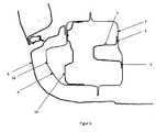
- FIG. 1 is a side sill, which is provided on the right and the left side of a motor vehicle body, designated 1. At the front of the side sill 1 protrudes from this an A-pillar 10 upwards. Approximately in the middle of the side sill 1 projects from this a middle B-pillar 11 upwards and at the end of the side sill 1 protrudes from this a C-pillar 12 upwards.
- the sill 1 consists essentially of a sheet metal inner part 2 and a connected thereto, outwardly projecting sheet outer part 4 (see, eg Fig. 3 ), which points outward, pointing away from the vehicle occupants.
- the sheet metal outer part 4 and other components are in FIG. 1 omitted in favor of improved clarity.
- the upper and lower ends of the inner plate part 2 can be connected in a known manner in each case with the upper and the lower end of the sheet metal outer part 4.
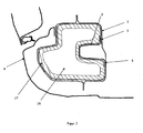
- a reinforcing member 3 is arranged, which has a extending in the vehicle longitudinal direction substantially U-shaped profile, which is apparent from the FIG. 3 is apparent.
- the free ends of the reinforcing member 3 are provided with feet 5, which are connected by a known connection technique, such as welding, gluing or riveting, with the inner plate part 2.
- the feet 5 are fixed to the inner plate part 2 by spot welding.
- the reinforcing member 3 extends from a region between the A pillar 10 and the B pillar 11 to a region between the B pillar 11 and the C pillar 12. Preferably, the reinforcing member 3 extends from the A pillar 10 to the C Column 12.
- the reinforcement part 3 can be manufactured from a sheet metal part and can also be produced in a cost-effective mass process, for example by roll forming or by extrusion profiling.
- a material for the reinforcing member 3 both steel materials and light metal materials, in particular aluminum can be used.
- the sheet metal outer part 4 is arranged between a plastic panel 6 and the inner plate part 2 and the plastic panel 6 extends from an upper area of the sheet metal outer part 4 to the lower edge of the inner panel part 2 and can be connected thereto e.g. be releasably connected by a clamping or snap action.
- the plastic panel 6 can be clipped on the upper edge of the sheet metal outer part 4 or the inner plate part 2 with this.
- a baffle element 7, 15 is arranged between the sheet outer part 4 and the reinforcement part 3 for transmitting lateral impact forces.
- FIG. 2 For example, a central baffle 7 between the A-pillar 10 and the B-pillar 11 and a central baffle 7 between the B-pillar 11 and the C-pillar 12 is shown. However, more than two or only one central impact element 7 can be provided.
- the baffles 7 have a substantially U-shaped cross section and are substantially vertically aligned ie the longitudinal axis of the U-shaped profile is transverse to the vehicle longitudinal direction.
- the outer contour of the impact element 7 is adapted to the contour of the sheet metal outer part 4, as shown in FIG. 4 is apparent. From the FIG. 5 It can be seen that the free ends 8 of the opposite walls of the U-shaped cross-section of the impact element 7 have a contour corresponding to the contour of the Sheet metal part 4 is adjusted.
- the central impact elements are designed to transmit a force acting from the vehicle side impact force.
- the opposite walls of the U-shaped cross section of the impact element 7 each have at least one perpendicular to the respective wall foot 9, which may be connected by welding, gluing or riveting or the like, with the sheet metal outer part 4.
- the bottom part 14 of the U-shaped cross section of the impact element 7 abuts against the reinforcement part 3, as shown in FIG. 5 is apparent.
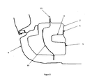
- vehicle body is a central baffle element 7 in the longitudinal direction of the sill 1 between a front baffle element 15 and a Abschottelement 16 is arranged.
- the front impact element 15 is arranged in the region of the A pillar 10 and between the outer sheet metal part 4, or the foot 18 of the A pillar, and the reinforcing part 3.
- the front impact element 15 is spaced from the sheet outer part 4 or the foot of the A-pillar 10, as shown in FIG. 6 is apparent.
- the front impact member 15 extends between the A pillar 10 and the reinforcing member 3 as far as a housing wall (not shown) of a wheel house (not shown).
- the front impact element 15 is designed to transmit an impact force acting from a vehicle front side, for example from a wheel.
- the front impact element 15 may also have a substantially U-shaped profile whose opposite walls are connected to the inside of the sheet metal outer part 4 by a known connection technique, such as welding, gluing or riveting.
- the front impact element 15 can be produced from a sheet metal part and can also be produced in a cost-effective mass method, for example by roll forming or by extrusion profiling.
- a material for front impact element 15 both steel materials and light metal materials, in particular aluminum can be used.
- FIG. 2 The vehicle body shown in each case a Abschottelement 16 between the central impact element 7 and the B-pillar is arranged.
- the sealing elements 16 are formed so that they hinder the passage of liquids and other moisture elements in the area between the sheet metal outer part 4 and the reinforcing member 3 in the vehicle longitudinal direction.
- the Abschottiata 16 are each surrounded by a swelling foam 17, as shown in FIG. 7 is apparent.
- the Abschottiata 16 also contribute to the further stiffening of the entire sill.
- the B-pillar 11 may have a reinforcing element 19 in the foot, which is arranged in the sill 1 between the reinforcing part 3 and the sheet metal outer part 4, as shown in FIGS Figures 2 and 8th is apparent.
Claims (4)
- Carrosserie de véhicule automobile dotée de longerons latéraux (1), pour l'essentiel composés d'une partie intérieure de tôle (2) et d'une partie extérieure de tôle (4) reliée à elle, saillant vers l'extérieur et d'une partie de renfort (3) disposée entre la partie intérieure de tôle (2) et la partie extérieure de tôle (4), le longeron latéral (1) et la partie de renfort (3) s'étendant entre un montant A (10) et un montant C (12), une extrémité supérieure et une extrémité inférieure de la partie intérieure de tôle (2) étant reliées à une extrémité supérieure et une extrémité inférieure de la partie extérieure de tôle (4), la partie de renfort (3) comportant dans la direction longitudinale du véhicule une section transversale pour l'essentiel en U, les extrémités libres de la section transversale de la partie (3) étant pourvues de pieds (5) reliés à la partie intérieure de tôle (2) et s'écartant de l'extrémité supérieure et inférieure de la partie intérieure de tôle (2) et/ou de la partie extérieure de tôle (4), au moins un élément pare-choc (7) comportant une section transversale en U orientée verticalement étant prévu entre la partie extérieure de tôle (4) et la partie de renfort (3) pour transmettre les forces de collision latérales, une partie de plancher (14) de l'élément pare-choc (7) en U reposant contre la partie de renfort (3) tandis que les extrémités libres (8) des parois opposées de l'élément pare-choc (7) en U adaptées au contour de la partie extérieure de tôles (4) sont reliées à la partie extérieure de tôle (4).
- Carrosserie de véhicule automobile selon la revendication 1, caractérisée en ce que l'élément pare-choc (7) est disposé entre le montant A (10) et un montant B (11) et qu'un autre élément pare-choc (7) est disposé entre le montant B (11) et le montant C (12).
- Carrosserie de véhicule automobile selon la revendication 1, caractérisée en ce que les parois opposées de la section transversale en U de l'élément pare-choc (7) comportent respectivement au moins un pied (9) perpendiculaire à la paroi respective reliée par soudage à la partie extérieure de tôle (4).
- Carrosserie de véhicule automobile selon les revendications 1 ou 2, caractérisée en ce que l'au moins un élément pare-choc (7) est disposé dans la direction longitudinale du longeron (1) entre un élément pare-choc avant (15) et un élément de cloisonnement (16).
Applications Claiming Priority (1)
| Application Number | Priority Date | Filing Date | Title |
|---|---|---|---|
| DE102007032244A DE102007032244A1 (de) | 2007-07-11 | 2007-07-11 | Kraftfahrzeugkarosserie mit seitlichen Schwellern |
Publications (2)
| Publication Number | Publication Date |
|---|---|
| EP2014539A1 EP2014539A1 (fr) | 2009-01-14 |
| EP2014539B1 true EP2014539B1 (fr) | 2010-07-21 |
Family
ID=39739349
Family Applications (1)
| Application Number | Title | Priority Date | Filing Date |
|---|---|---|---|
| EP08009438A Expired - Fee Related EP2014539B1 (fr) | 2007-07-11 | 2008-05-23 | Carrosserie de véhicule automobile dotée de longerons latéraux |
Country Status (2)
| Country | Link |
|---|---|
| EP (1) | EP2014539B1 (fr) |
| DE (2) | DE102007032244A1 (fr) |
Cited By (1)
| Publication number | Priority date | Publication date | Assignee | Title |
|---|---|---|---|---|
| DE202023000698U1 (de) | 2023-03-29 | 2023-05-03 | Gerhard Stegh | KFZ-Tür mit Schweller |
Families Citing this family (11)
| Publication number | Priority date | Publication date | Assignee | Title |
|---|---|---|---|---|
| DE102009042188A1 (de) * | 2009-09-18 | 2011-03-24 | Audi Ag | Fahrzeugkarosserieaufbau im Bereich A-Säule unten und Schweller und zugeordnetes Fertigungsverfahren |
| DE102009058976A1 (de) * | 2009-12-18 | 2011-06-22 | Audi Ag, 85057 | Schwellerbaugruppe für eine Fahrzeugkarosserie sowie Verfahren zur Herstellung einer Schwellerbaugruppe |
| FR2976250B1 (fr) * | 2011-06-10 | 2013-06-28 | Peugeot Citroen Automobiles Sa | Longeron de bas de caisse pour vehicule automobile et vehicule equipe de tels longerons. |
| DE102012012745A1 (de) * | 2012-06-27 | 2014-01-02 | Daimler Ag | Trägerelement und Energieabsorptionselement in Hybridbauweise für einen Kraftwagen |
| GB2505671A (en) * | 2012-09-06 | 2014-03-12 | Jaguar Land Rover Ltd | Vehicle jacking point and reinforcement insert |
| DE102013201558A1 (de) | 2013-01-30 | 2014-07-31 | Bayerische Motoren Werke Aktiengesellschaft | Kraftfahrzeug |
| FR3027274B1 (fr) * | 2014-10-20 | 2018-03-23 | Psa Automobiles Sa. | Longeron de bas de caisse de vehicule avec raidisseur et cloisons. |
| US10155542B2 (en) | 2016-01-22 | 2018-12-18 | Ford Global Technologies, Llc | Stepped honeycomb rocker insert |
| US10029734B2 (en) | 2016-01-22 | 2018-07-24 | Ford Global Technologies, Llc | Rocker insert formed by connected tubular members |
| GB2566301B (en) * | 2017-09-08 | 2020-09-16 | Jaguar Land Rover Ltd | Sill assembly |
| WO2021234433A1 (fr) * | 2020-05-18 | 2021-11-25 | Arcelormittal | Renfort de bas de caisse pour véhicule électrique |
Citations (1)
| Publication number | Priority date | Publication date | Assignee | Title |
|---|---|---|---|---|
| DE102005038463A1 (de) * | 2005-08-13 | 2007-02-15 | Daimlerchrysler Ag | Träger einer Kraftwagenkarosserie |
Family Cites Families (11)
| Publication number | Priority date | Publication date | Assignee | Title |
|---|---|---|---|---|
| JPS6418784A (en) | 1987-07-14 | 1989-01-23 | Mazda Motor | Side sill structure of automobile |
| JPH0481371A (ja) | 1990-07-23 | 1992-03-16 | Nissan Motor Co Ltd | 車体閉断面構造部材 |
| DE19528874C2 (de) | 1995-08-05 | 1998-02-26 | Volkswagen Ag | Tragstruktur für ein Fahrzeug |
| JP3478317B2 (ja) | 1996-08-21 | 2003-12-15 | 三菱自動車工業株式会社 | ボデーの構造 |
| DE19710894B4 (de) * | 1997-03-15 | 2006-04-13 | Adam Opel Ag | Wandstruktur |
| JP3951507B2 (ja) | 1999-06-11 | 2007-08-01 | スズキ株式会社 | 自動車の側部車体構造 |
| DE10003878B4 (de) * | 2000-01-28 | 2004-05-13 | Linde + Pullman Ag | Zusatzelement |
| US6834912B2 (en) * | 2002-10-18 | 2004-12-28 | Honda Motor Co., Ltd. | Structure for controlled deformation of body side structure |
| DE10304307B4 (de) * | 2003-02-04 | 2008-01-31 | Bayerische Motoren Werke Ag | Kraftfahrzeugkarosserie mit seitlichen Schwellern |
| JP4220971B2 (ja) | 2005-02-10 | 2009-02-04 | 本田技研工業株式会社 | 自動車の後部車体構造 |
| JP4483830B2 (ja) * | 2006-05-29 | 2010-06-16 | トヨタ自動車株式会社 | 車体下部構造 |
-
2007
- 2007-07-11 DE DE102007032244A patent/DE102007032244A1/de not_active Withdrawn
-
2008
- 2008-05-23 EP EP08009438A patent/EP2014539B1/fr not_active Expired - Fee Related
- 2008-05-23 DE DE200850000976 patent/DE502008000976D1/de active Active
Patent Citations (1)
| Publication number | Priority date | Publication date | Assignee | Title |
|---|---|---|---|---|
| DE102005038463A1 (de) * | 2005-08-13 | 2007-02-15 | Daimlerchrysler Ag | Träger einer Kraftwagenkarosserie |
Cited By (1)
| Publication number | Priority date | Publication date | Assignee | Title |
|---|---|---|---|---|
| DE202023000698U1 (de) | 2023-03-29 | 2023-05-03 | Gerhard Stegh | KFZ-Tür mit Schweller |
Also Published As
| Publication number | Publication date |
|---|---|
| EP2014539A1 (fr) | 2009-01-14 |
| DE502008000976D1 (de) | 2010-09-02 |
| DE102007032244A1 (de) | 2009-01-15 |
Similar Documents
| Publication | Publication Date | Title |
|---|---|---|
| EP2014539B1 (fr) | Carrosserie de véhicule automobile dotée de longerons latéraux | |
| DE102010036450B4 (de) | B-Säulenverstärkung eines Kraftfahrzeugs | |
| EP1216865B1 (fr) | Porte légère pour véhicules à moteur | |
| EP1738943B1 (fr) | Structure de porte d'un véhicule automobile | |
| DE102007032245A1 (de) | Kraftfahrzeugkarosserie mit seitlichen Schwellern | |
| DE102008056507B4 (de) | Fahrzeugaufbau für ein Kraftfahrzeug | |
| DE102012216349A1 (de) | Dachaufbau für ein fahrzeug ohne mittelsäule | |
| DE102013004852A1 (de) | Schweller für eine Fahrzeugkarosserie | |
| DE10028716B4 (de) | Karosserieseitenteilkonstruktion für ein Automobil | |
| DE102006014962A1 (de) | Schwellerverstärkungselement für eine Fahrzeugkarosserie | |
| EP0897853B1 (fr) | Véhicule automobile avec renforcements dans la région des montants 'B' | |
| DE102016209186B3 (de) | Karosseriestruktur für ein Kraftfahrzeug | |
| DE102008045914A1 (de) | Rohranordnung sowie Querträger mit einer solchen Rohranordnung | |
| DE202014103276U1 (de) | Kurze Versatz-Blechverstärkung zur Begrenzung der Rotation während eines Unfalls | |
| DE102018103360A1 (de) | Fahrzeugkarosserie mit verstärkung auf dem schwellerblech | |
| DE102012205882A1 (de) | Fahrzeugdachstützenanordnung | |
| EP3519278A1 (fr) | Élément structural pour une carrosserie de véhicule automobile | |
| DE102009004886B4 (de) | Aufbaustruktur | |
| DE102020107343B4 (de) | Kraftfahrzeug mit einer Schwelleranordnung | |
| EP1736397A2 (fr) | Structure arrière de carrosserie de véhicule automobile | |
| DE102007032246B4 (de) | Kraftfahrzeugkarosserie mit seitlichen Schwellern | |
| DE60024829T2 (de) | Profil für eine Karosserie | |
| DE102006015414B4 (de) | Trägerhohlprofil für ein Kraftfahrzeug | |
| DE102005044063A1 (de) | Karosseriesäule eines Kraftfahrzeugs, seitlicher Dachkanal und dreischenkelige Knotenverbindung | |
| DE102015204917A1 (de) | Seitentür für ein Fahrzeug sowie Fahrzeug mit einer derartigen Seitentür |
Legal Events
| Date | Code | Title | Description |
|---|---|---|---|
| PUAI | Public reference made under article 153(3) epc to a published international application that has entered the european phase |
Free format text: ORIGINAL CODE: 0009012 |
|
| AK | Designated contracting states |
Kind code of ref document: A1 Designated state(s): AT BE BG CH CY CZ DE DK EE ES FI FR GB GR HR HU IE IS IT LI LT LU LV MC MT NL NO PL PT RO SE SI SK TR |
|
| AX | Request for extension of the european patent |
Extension state: AL BA MK RS |
|
| 17P | Request for examination filed |
Effective date: 20090714 |
|
| AKX | Designation fees paid |
Designated state(s): DE FR GB IT |
|
| 17Q | First examination report despatched |
Effective date: 20090819 |
|
| RAP1 | Party data changed (applicant data changed or rights of an application transferred) |
Owner name: DR. ING. H.C. F. PORSCHE AG |
|
| GRAP | Despatch of communication of intention to grant a patent |
Free format text: ORIGINAL CODE: EPIDOSNIGR1 |
|
| GRAS | Grant fee paid |
Free format text: ORIGINAL CODE: EPIDOSNIGR3 |
|
| GRAA | (expected) grant |
Free format text: ORIGINAL CODE: 0009210 |
|
| AK | Designated contracting states |
Kind code of ref document: B1 Designated state(s): DE FR GB IT |
|
| REG | Reference to a national code |
Ref country code: GB Ref legal event code: FG4D Free format text: NOT ENGLISH |
|
| REF | Corresponds to: |
Ref document number: 502008000976 Country of ref document: DE Date of ref document: 20100902 Kind code of ref document: P |
|
| PLBE | No opposition filed within time limit |
Free format text: ORIGINAL CODE: 0009261 |
|
| STAA | Information on the status of an ep patent application or granted ep patent |
Free format text: STATUS: NO OPPOSITION FILED WITHIN TIME LIMIT |
|
| 26N | No opposition filed |
Effective date: 20110426 |
|
| REG | Reference to a national code |
Ref country code: DE Ref legal event code: R097 Ref document number: 502008000976 Country of ref document: DE Effective date: 20110426 |
|
| REG | Reference to a national code |
Ref country code: FR Ref legal event code: PLFP Year of fee payment: 9 |
|
| REG | Reference to a national code |
Ref country code: FR Ref legal event code: PLFP Year of fee payment: 10 |
|
| REG | Reference to a national code |
Ref country code: FR Ref legal event code: PLFP Year of fee payment: 11 |
|
| PGFP | Annual fee paid to national office [announced via postgrant information from national office to epo] |
Ref country code: IT Payment date: 20180530 Year of fee payment: 11 |
|
| PGFP | Annual fee paid to national office [announced via postgrant information from national office to epo] |
Ref country code: FR Payment date: 20190523 Year of fee payment: 12 |
|
| PGFP | Annual fee paid to national office [announced via postgrant information from national office to epo] |
Ref country code: GB Payment date: 20190521 Year of fee payment: 12 |
|
| PG25 | Lapsed in a contracting state [announced via postgrant information from national office to epo] |
Ref country code: IT Free format text: LAPSE BECAUSE OF NON-PAYMENT OF DUE FEES Effective date: 20190523 |
|
| PGFP | Annual fee paid to national office [announced via postgrant information from national office to epo] |
Ref country code: DE Payment date: 20200430 Year of fee payment: 13 |
|
| GBPC | Gb: european patent ceased through non-payment of renewal fee |
Effective date: 20200523 |
|
| PG25 | Lapsed in a contracting state [announced via postgrant information from national office to epo] |
Ref country code: GB Free format text: LAPSE BECAUSE OF NON-PAYMENT OF DUE FEES Effective date: 20200523 Ref country code: FR Free format text: LAPSE BECAUSE OF NON-PAYMENT OF DUE FEES Effective date: 20200531 |
|
| REG | Reference to a national code |
Ref country code: DE Ref legal event code: R119 Ref document number: 502008000976 Country of ref document: DE |
|
| PG25 | Lapsed in a contracting state [announced via postgrant information from national office to epo] |
Ref country code: DE Free format text: LAPSE BECAUSE OF NON-PAYMENT OF DUE FEES Effective date: 20211201 |