EP2014539B1 - Motor vehicle body with side sills - Google Patents
Motor vehicle body with side sills Download PDFInfo
- Publication number
- EP2014539B1 EP2014539B1 EP08009438A EP08009438A EP2014539B1 EP 2014539 B1 EP2014539 B1 EP 2014539B1 EP 08009438 A EP08009438 A EP 08009438A EP 08009438 A EP08009438 A EP 08009438A EP 2014539 B1 EP2014539 B1 EP 2014539B1
- Authority
- EP
- European Patent Office
- Prior art keywords
- sheet
- pillar
- sill
- metal outer
- outer part
- Prior art date
- Legal status (The legal status is an assumption and is not a legal conclusion. Google has not performed a legal analysis and makes no representation as to the accuracy of the status listed.)
- Expired - Fee Related
Links
Images


Classifications
-
- B—PERFORMING OPERATIONS; TRANSPORTING
- B62—LAND VEHICLES FOR TRAVELLING OTHERWISE THAN ON RAILS
- B62D—MOTOR VEHICLES; TRAILERS
- B62D21/00—Understructures, i.e. chassis frame on which a vehicle body may be mounted
- B62D21/15—Understructures, i.e. chassis frame on which a vehicle body may be mounted having impact absorbing means, e.g. a frame designed to permanently or temporarily change shape or dimension upon impact with another body
- B62D21/157—Understructures, i.e. chassis frame on which a vehicle body may be mounted having impact absorbing means, e.g. a frame designed to permanently or temporarily change shape or dimension upon impact with another body for side impacts
-
- B—PERFORMING OPERATIONS; TRANSPORTING
- B62—LAND VEHICLES FOR TRAVELLING OTHERWISE THAN ON RAILS
- B62D—MOTOR VEHICLES; TRAILERS
- B62D25/00—Superstructure or monocoque structure sub-units; Parts or details thereof not otherwise provided for
- B62D25/02—Side panels
-
- B—PERFORMING OPERATIONS; TRANSPORTING
- B62—LAND VEHICLES FOR TRAVELLING OTHERWISE THAN ON RAILS
- B62D—MOTOR VEHICLES; TRAILERS
- B62D25/00—Superstructure or monocoque structure sub-units; Parts or details thereof not otherwise provided for
- B62D25/02—Side panels
- B62D25/025—Side sills thereof
Definitions
- the invention relates to a motor vehicle body with a side sill.
- the sill of a motor vehicle is an essential support and support element of a support structure of a motor vehicle.
- the sill should represent a stable barrier in a side crash against a depression of the passenger compartment.
- the sill is provided with reinforcing elements in order to increase the rigidity of the sill.
- a door sill known with an outer shell and an inner shell and a web plate.
- the latter divides the formed in the manner of a hollow profile carrier door sill in a first hollow chamber and a second hollow chamber.
- a profile arrangement is provided, the essential elements of which are a longitudinally extending profile part and a spacer profile part. These form together with the web plate together a composite component and may optionally be connected to at least one of the two shells of the door sill.
- Both the profile part and the spacer profile part are hat-shaped or horn-like and have surface trained force application areas, which are either directly connected to the surrounded sheet metal shells or have these only a small distance.
- a side sill with a closed cross section is known, which is formed by a body side panel and a side sill plate. Within the closed cross-section are an outer side sill reinforcement and an inner side sill reinforcement.
- the JP 04 081371 A discloses a motor vehicle body with a side sill, which consists of a sheet metal inner part, a sheet metal outer part and an intermediate composed of the inner plate part and the sheet metal outer part arranged reinforcement part.
- a vertical flat wall reinforcing member is respectively firmly connected to the upper and lower ends of the inner plate part and the sheet metal outer part and divides the sill into an outer and an inner hollow chamber.
- impact elements are provided in two hollow chambers, which are fixed to the plate-shaped reinforcement member.
- the outer baffle extends over a substantial part of its height extent at a distance from the adjacent sheet metal outer part.
- the sill is formed by a sheet metal inner part, a sheet metal outer part and a profiled reinforcing part.
- the profiled reinforcing member extends over the entire height of the sill and is respectively connected to upper and lower parked flanges of the inner plate part and the sheet metal outer part.
- An impact element for transmitting lateral impact forces is provided between the profiled reinforcement part and the inner plate part, but not between the sheet outer part and the reinforcement part.
- the profiled reinforcing plate of the sill is also connected to the upper and lower parked flanges of the inner plate part and the sheet metal outer part and in the region of a bottom-side cross member between the reinforcing plate and the inner plate part of the sill, a baffle element for transmitting lateral impact forces.
- This baffle element is connected to the profiled reinforcing plate and extends at a distance to the inner plate part.
- the JP 01018784 A shows a sill of a motor vehicle body, wherein within the consisting of a sheet metal outer part and a sheet metal inner door sill an elongated stiffening tube is arranged, which is connected via local junction plates with the inner plate part and the sheet metal outer part.
- the DE102005038463 A shows a motor vehicle body with a side sill consisting of a metal inner part and a connected thereto, outwardly projecting sheet outer part and arranged between the inner plate part and the sheet metal outer reinforcement part.
- the upper and lower ends of the inner plate part are connected to the upper and lower ends of the sheet outer part and the reinforcing member has a substantially U-shaped cross-section in the vehicle longitudinal direction, wherein the free ends of the reinforcing member are provided with feet which are spaced from the upper and lower ends of the inner plate part or the outer sheet metal part are connected to the inner plate part.
- the present invention addresses the problem of providing a vehicle body with a side sill which provides improved side impact protection.
- the invention is based on the general idea to provide a motor vehicle body with a side sill, wherein between a plate inner part and a sheet outer part of the sill a reinforcing member is arranged, wherein the side sill and the reinforcing member between an A-pillar and a C-pillar, and between the outer sheet metal part and the reinforcing part for transmitting lateral impact forces at least one baffle element is provided, whose outer contour is adapted to the contour of the sheet metal outer part.
- a baffle element between the A-pillar and a B-pillar is arranged and a further baffle element is arranged between the B-pillar and the C-pillar. This allows the sill to be reinforced in critical areas.
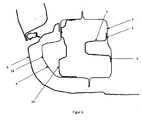
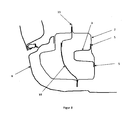
- FIG. 1 is a side sill, which is provided on the right and the left side of a motor vehicle body, designated 1. At the front of the side sill 1 protrudes from this an A-pillar 10 upwards. Approximately in the middle of the side sill 1 projects from this a middle B-pillar 11 upwards and at the end of the side sill 1 protrudes from this a C-pillar 12 upwards.
- the sill 1 consists essentially of a sheet metal inner part 2 and a connected thereto, outwardly projecting sheet outer part 4 (see, eg Fig. 3 ), which points outward, pointing away from the vehicle occupants.
- the sheet metal outer part 4 and other components are in FIG. 1 omitted in favor of improved clarity.
- the upper and lower ends of the inner plate part 2 can be connected in a known manner in each case with the upper and the lower end of the sheet metal outer part 4.
- a reinforcing member 3 is arranged, which has a extending in the vehicle longitudinal direction substantially U-shaped profile, which is apparent from the FIG. 3 is apparent.
- the free ends of the reinforcing member 3 are provided with feet 5, which are connected by a known connection technique, such as welding, gluing or riveting, with the inner plate part 2.
- the feet 5 are fixed to the inner plate part 2 by spot welding.
- the reinforcing member 3 extends from a region between the A pillar 10 and the B pillar 11 to a region between the B pillar 11 and the C pillar 12. Preferably, the reinforcing member 3 extends from the A pillar 10 to the C Column 12.
- the reinforcement part 3 can be manufactured from a sheet metal part and can also be produced in a cost-effective mass process, for example by roll forming or by extrusion profiling.
- a material for the reinforcing member 3 both steel materials and light metal materials, in particular aluminum can be used.
- the sheet metal outer part 4 is arranged between a plastic panel 6 and the inner plate part 2 and the plastic panel 6 extends from an upper area of the sheet metal outer part 4 to the lower edge of the inner panel part 2 and can be connected thereto e.g. be releasably connected by a clamping or snap action.
- the plastic panel 6 can be clipped on the upper edge of the sheet metal outer part 4 or the inner plate part 2 with this.
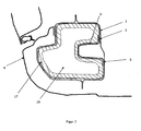
- a baffle element 7, 15 is arranged between the sheet outer part 4 and the reinforcement part 3 for transmitting lateral impact forces.
- FIG. 2 For example, a central baffle 7 between the A-pillar 10 and the B-pillar 11 and a central baffle 7 between the B-pillar 11 and the C-pillar 12 is shown. However, more than two or only one central impact element 7 can be provided.
- the baffles 7 have a substantially U-shaped cross section and are substantially vertically aligned ie the longitudinal axis of the U-shaped profile is transverse to the vehicle longitudinal direction.
- the outer contour of the impact element 7 is adapted to the contour of the sheet metal outer part 4, as shown in FIG. 4 is apparent. From the FIG. 5 It can be seen that the free ends 8 of the opposite walls of the U-shaped cross-section of the impact element 7 have a contour corresponding to the contour of the Sheet metal part 4 is adjusted.
- the central impact elements are designed to transmit a force acting from the vehicle side impact force.
- the opposite walls of the U-shaped cross section of the impact element 7 each have at least one perpendicular to the respective wall foot 9, which may be connected by welding, gluing or riveting or the like, with the sheet metal outer part 4.
- the bottom part 14 of the U-shaped cross section of the impact element 7 abuts against the reinforcement part 3, as shown in FIG. 5 is apparent.
- vehicle body is a central baffle element 7 in the longitudinal direction of the sill 1 between a front baffle element 15 and a Abschottelement 16 is arranged.
- the front impact element 15 is arranged in the region of the A pillar 10 and between the outer sheet metal part 4, or the foot 18 of the A pillar, and the reinforcing part 3.
- the front impact element 15 is spaced from the sheet outer part 4 or the foot of the A-pillar 10, as shown in FIG. 6 is apparent.
- the front impact member 15 extends between the A pillar 10 and the reinforcing member 3 as far as a housing wall (not shown) of a wheel house (not shown).
- the front impact element 15 is designed to transmit an impact force acting from a vehicle front side, for example from a wheel.
- the front impact element 15 may also have a substantially U-shaped profile whose opposite walls are connected to the inside of the sheet metal outer part 4 by a known connection technique, such as welding, gluing or riveting.
- the front impact element 15 can be produced from a sheet metal part and can also be produced in a cost-effective mass method, for example by roll forming or by extrusion profiling.
- a material for front impact element 15 both steel materials and light metal materials, in particular aluminum can be used.
- FIG. 2 The vehicle body shown in each case a Abschottelement 16 between the central impact element 7 and the B-pillar is arranged.
- the sealing elements 16 are formed so that they hinder the passage of liquids and other moisture elements in the area between the sheet metal outer part 4 and the reinforcing member 3 in the vehicle longitudinal direction.
- the Abschottiata 16 are each surrounded by a swelling foam 17, as shown in FIG. 7 is apparent.
- the Abschottiata 16 also contribute to the further stiffening of the entire sill.
- the B-pillar 11 may have a reinforcing element 19 in the foot, which is arranged in the sill 1 between the reinforcing part 3 and the sheet metal outer part 4, as shown in FIGS Figures 2 and 8th is apparent.
Description
Die Erfindung betrifft eine Kraftfahrzeugkarosserie mit einem seitlichen Schweller.The invention relates to a motor vehicle body with a side sill.
Der Schweller eines Kraftfahrzeugs ist ein wesentliches Trag- und Stützelement einer Tragstruktur eines Kraftfahrzeugs. Insbesondere soll der Schweller eine stabile Barriere bei einem Seitencrash gegen eine Eindrückung der Fahrgastzelle darstellen. Nach dem Stand der Technik wird der Schweller mit Verstärkungselementen versehen, um die Steifigkeit des Schwellers zu erhöhen.The sill of a motor vehicle is an essential support and support element of a support structure of a motor vehicle. In particular, the sill should represent a stable barrier in a side crash against a depression of the passenger compartment. According to the prior art, the sill is provided with reinforcing elements in order to increase the rigidity of the sill.
Aus der
Aus der
Die
Bei der
Gemäß der
Die
Die
Die vorliegende Erfindung beschäftigt sich mit dem Problem, eine Kraftfahrzeugkarosserie mit einem seitlichen Schweller bereitzustellen, bei dem ein verbesserter Schutz gegenüber Aufprallkräften von der Seite gewährleistet wird.The present invention addresses the problem of providing a vehicle body with a side sill which provides improved side impact protection.
Dieses Problem wird erfindungsgemäß durch den Gegenstand des unabhängigen Anspruchs 1 gelöst. Vorteilhafte Ausführungsformen sind Gegenstand der abhängigen Ansprüche.This problem is solved according to the invention by the subject matter of
Die Erfindung beruht auf dem allgemeinen Gedanken, eine Kraftfahrzeugkarosserie mit einem seitlichen Schweller bereitzustellen, wobei zwischen einem Blechinnenteil und einem Blechaußenteil des Schwellers ein Verstärkungsteil angeordnet ist, wobei sich der seitliche Schweller und das Verstärkungsteil zwischen einer A-Säule und einer C-Säule erstrecken, und zwischen dem Blechaußenteil und dem Verstärkungsteil zur Übertragung von seitlichen Aufprallkräften mindestens ein Prallelement vorgesehen ist, dessen Außenkontur der Kontur des Blechaußenteils angepasst ist.The invention is based on the general idea to provide a motor vehicle body with a side sill, wherein between a plate inner part and a sheet outer part of the sill a reinforcing member is arranged, wherein the side sill and the reinforcing member between an A-pillar and a C-pillar, and between the outer sheet metal part and the reinforcing part for transmitting lateral impact forces at least one baffle element is provided, whose outer contour is adapted to the contour of the sheet metal outer part.
Durch die Anpassung der Prallelementaußenkontur an die Kontur des Blechaußenteils wird eine verbesserte Übertragung von seitlichen Aufprallkräften erzielt.By adapting the impact element outer contour to the contour of the outer sheet metal part, an improved transmission of lateral impact forces is achieved.
Gemäß einer bevorzugten Ausgestaltung der erfindungsgemäßen Kraftfahrzeugkarosserie ist ein Prallelement zwischen der A-Säule und einer B-Säule angeordnet und ein weiteres Prallelement ist zwischen der B-Säule und der C-Säule angeordnet. Hierdurch kann der Schweller in kritischen Stellen verstärkt werden.According to a preferred embodiment of the motor vehicle body according to the invention, a baffle element between the A-pillar and a B-pillar is arranged and a further baffle element is arranged between the B-pillar and the C-pillar. This allows the sill to be reinforced in critical areas.
Weitere wichtige Merkmale und Vorteile der Erfindung ergeben sich aus den Unteransprüchen, aus den Zeichnungen und aus der zugehörigen Figurenbeschreibung anhand der Zeichnungen.Other important features and advantages of the invention will become apparent from the dependent claims, from the drawings and from the associated figure description with reference to the drawings.
Es versteht sich, dass die vorstehend genannten und die nachstehend noch zu erläuternden Merkmale nicht nur in der jeweils angegebenen Kombination, sondern auch in anderen Kombinationen oder in Alleinstellung verwendbar sind, ohne den Rahmen der vorliegenden Erfindung zu verlassen.It is understood that the features mentioned above and those yet to be explained not only in the combination specified, but also in other combinations or in isolation, without departing from the scope of the present invention.
Bevorzugte Ausführungsbeispiele der Erfindung sind in den Zeichnungen dargestellt und werden in der nachfolgenden Beschreibung näher erläutert, wobei sich gleiche Bezugszeichen auf gleiche oder ähnliche oder funktional gleiche Bauteile beziehen.Preferred embodiments of the invention are illustrated in the drawings and will be described in more detail in the following description, wherein like reference numerals refer to the same or similar or functionally identical components.
Es zeigen, jeweils schematisch,
- Fig. 1
- die Beziehung zwischen dem Blechinnenteil und dem Verstärkungsteil in einer perspektivischen Ansicht nach einem Ausführungsbeispiel der Erfindung,
- Fig. 2
- die Beziehung zwischen dem Blechinnenteil und anderen Bauteilen in einer perspektivischen Ansicht nach einem Ausführungsbeispiel der Erfindung,
- Fig. 3
- ein Querschnitt an einer Stelle in Längsrichtung durch einen Schweller nach einem Ausführungsbeispiel der Erfindung,
- Fig. 4
- die Beziehung zwischen dem Blechaußenteil und einem Prallelement im Querschnitt nach einem Ausführungsbeispiel der Erfindung,
- Fig. 5
- in einer perspektivischen Ansicht ein Prallelement in einem Schweller nach einem Ausführungsbeispiel der Erfindung,
- Fig. 6
- im Querschnitt die Beziehung zwischen einem Vorderprallelement und anderen Elementen im Schweller nach einem Ausführungsbeispiel der Erfindung,
- Fig. 7
- im Querschnitt die Beziehung zwischen einem Abschottelement und anderen Elementen im Schweller nach einem Ausführungsbeispiel der Erfindung,
- Fig. 8
- einen Querschnitt durch den Schweller an einer B-Säule nach einem Ausführungsbeispiel der Erfindung.
- Fig. 1
- the relationship between the inner plate part and the reinforcing part in a perspective view according to an embodiment of the invention,
- Fig. 2
- the relationship between the inner plate part and other components in a perspective view according to an embodiment of the invention,
- Fig. 3
- a cross section at a position in the longitudinal direction through a sill according to an embodiment of the invention,
- Fig. 4
- the relationship between the sheet metal outer part and a baffle element in cross section according to an embodiment of the invention,
- Fig. 5
- in a perspective view of a baffle element in a sill according to an embodiment of the invention,
- Fig. 6
- in cross-section the relationship between a front impact element and other elements in the sill according to an embodiment of the invention,
- Fig. 7
- in cross-section the relationship between a Abschottelement and other elements in the sill according to an embodiment of the invention,
- Fig. 8
- a cross section through the sill on a B-pillar according to an embodiment of the invention.
In
Der Schweller 1 besteht im Wesentlichen aus einem Blechinnenteil 2 und einem mit diesem verbundenen, nach außen abstehenden Blechaußenteil 4 (vgl. z.B.
Das obere und das untere Ende des Blechinnenteils 2 können auf bekannte Weise jeweils mit dem oberen und dem unteren Ende des Blechaußenteils 4 verbunden werden.The upper and lower ends of the
Zwischen dem Blechinnenteil 2 und dem Blechaußenteil 4 ist ein Verstärkungsteil 3 angeordnet, das ein sich in Fahrzeuglängsrichtung erstreckendes im Wesentlichen U-förmiges Profil aufweist, was aus der
Das Verstärkungsteil 3 erstreckt von einem Bereich zwischen der A-Säule 10 und der B-Säule 11 zu einem Bereich zwischen der B-Säule 11 und der C-Säule 12. Vorzugsweise erstreckt das Verstärkungsteil 3 von der A-Säule 10 bis zu der C-Säule 12.The reinforcing
Das Verstärkungsteil 3 kann aus einem Blechteil gefertigt werden und kann auch in einem kostengünstigen Massenverfahren beispielsweise durch Walzprofilierung oder durch Strangpressprofilierung hergestellt werden. Als Material für das Verstärkungsteil 3 können sowohl Stahlwerkstoffe als auch Leichtmetallwerkstoffe, insbesondere Aluminium verwendet werden.The
Das Blechaußenteil 4 ist zwischen einer Kunststoffblende 6 und dem Blechinnenteil 2 angeordnet und die Kunststoffblende 6 erstreckt sich von einem oberen Beriech des Blechaußenteils 4 bis zum untenliegenden Rand des Blechinnenteils 2 und kann mit diesem z.B. durch eine Klemm- oder Schnappwirkung lösbar verbunden sein. Die Kunststoffblende 6 kann am obenliegenden Rand des Blechaußenteils 4 oder des Blechinnenteils 2 mit diesem verclipst sein.The sheet metal outer part 4 is arranged between a
An mindestens einer Stelle in Längsrichtung des Schwellers 1 ist ein Prallelement 7, 15 zwischen dem Blechaußenteil 4 und dem Verstärkungsteil 3 zur Übertragung von seitlichen Aufprallkräften angeordnet. In
Die Prallelemente 7 weisen einen im Wesentlichen U-förmigen Querschnitt auf und sind im Wesentlichen vertikal ausgerichtet d.h. die Längsachse des U-förmigen Profils liegt quer zur Fahrzeuglängsrichtung. Die Außenkontur des Prallelements 7 ist der Kontur des Blechaußenteils 4 angepasst, wie aus der
Des Weiteren weisen die gegenüberliegenden Wände des U-förmigen Querschnitts des Prallelements 7 jeweils mindestens einen zu der jeweiligen Wand lotrechten Fuß 9 auf, der durch Schweißen, Verkleben oder Nieten oder ähnlichen, mit dem Blechaußenteil 4 verbunden sein kann. Der Bodenteil 14 des U-förmigen Querschnitts des Prallelements 7 liegt an dem Verstärkungsteil 3 an, wie aus der
In der in
In der in
Die B-Säule 11 kann im Fuß ein Verstärkungselement 19 aufweisen, das im Schweller 1 zwischen dem Verstärkungsteil 3 und dem Blechaußenteil 4 angeordnet ist, wie aus den
Die vorhergehende Beschreibung der Ausführungsbeispiele gemäß der vorliegenden Erfindung dient nur zu illustrativen Zwecken und nicht zum Zwecke der Beschränkung der Erfindung. Insbesondere im Hinblick auf einige bevorzugte Ausführungsbeispiele entnimmt ihr der Fachmann, dass verschiedene Änderungen und Modifikationen in Gestalt und Einzelheiten gemacht werden können, ohne von dem Gedanken und Umfang der Erfindung abzuweichen. Dementsprechend soll die Offenbarung der vorliegenden Erfindung nicht einschränkend sein. Stattdessen soll die Offenbarung der vorliegenden Erfindung den Umfang der Erfindung veranschaulichen, der in den nachfolgenden Ansprüchen dargelegt ist.The foregoing description of the embodiments according to the present invention is for illustrative purposes only, and not for the purpose of limiting the invention. With particular reference to some preferred embodiments, those skilled in the art will appreciate that various changes and modifications in form and detail may be made without departing from the spirit and scope of the invention. Accordingly, the disclosure of the present invention is not intended to be limiting. Instead, the disclosure of the present invention is intended to illustrate the scope of the invention, which is set forth in the following claims.
Claims (4)
- Motor vehicle body with a side sill (1), essentially consisting of a sheet-metal inner part (2) and an outwardly protruding sheet-metal outer part (4) which is connected to the latter, and a reinforcing part (3) arranged between the sheet-metal inner part (2) and the sheet-metal outer part (4), wherein the side sill (1) and the reinforcing part (3) extend between an A pillar (10) and a C pillar (12), wherein an upper and a lower end of the sheet-metal inner part (2) is connected to an upper and a lower end of the sheet-metal outer part (4), wherein the reinforcing part (3) has a substantially U-shaped cross section in the longitudinal direction of the vehicle, wherein the free ends of the cross section of the reinforcing part (3) are provided with feet (5) which are connected to the sheet-metal inner part (2) at a distance from the upper and lower ends of the sheet-metal inner part (2) and of the sheet-metal outer part (4), wherein at least one impact element (7) which has a U-shaped cross section and is vertically oriented is provided between the sheet-metal outer part (4) and the reinforcing part (3) in order to transmit lateral impact forces, and wherein a bottom part (14) of the U-shaped impact element (7) bears against the reinforcing part (3) while the free ends (8) of the opposite walls of the U-shaped impact element (7) are matched to the contour of the sheet-metal outer part (4) and are connected to the sheet-metal outer part (4).
- Motor vehicle body according to Claim 1, characterized in that the impact element (7) is arranged between the A pillar (10) and a B pillar (11) and a further impact element (7) is arranged between the B pillar (11) and the C pillar (12).
- Motor vehicle body according to Claim 1, characterized in that the opposite walls of the U-shaped cross section of the impact element (7) each have at least one foot (9) which is perpendicular to the respective wall and is connected to the sheet-metal outer part (4) by welding.
- Motor vehicle body according to Claims 1 or 2, characterized in that the at least one impact element (7) is arranged in the longitudinal direction of the sill (1) between a front impact element (15) and a bulkhead element (16).
Applications Claiming Priority (1)
| Application Number | Priority Date | Filing Date | Title |
|---|---|---|---|
| DE102007032244A DE102007032244A1 (en) | 2007-07-11 | 2007-07-11 | Motor vehicle body with side sills |
Publications (2)
| Publication Number | Publication Date |
|---|---|
| EP2014539A1 EP2014539A1 (en) | 2009-01-14 |
| EP2014539B1 true EP2014539B1 (en) | 2010-07-21 |
Family
ID=39739349
Family Applications (1)
| Application Number | Title | Priority Date | Filing Date |
|---|---|---|---|
| EP08009438A Expired - Fee Related EP2014539B1 (en) | 2007-07-11 | 2008-05-23 | Motor vehicle body with side sills |
Country Status (2)
| Country | Link |
|---|---|
| EP (1) | EP2014539B1 (en) |
| DE (2) | DE102007032244A1 (en) |
Cited By (1)
| Publication number | Priority date | Publication date | Assignee | Title |
|---|---|---|---|---|
| DE202023000698U1 (en) | 2023-03-29 | 2023-05-03 | Gerhard Stegh | Car door with sill |
Families Citing this family (11)
| Publication number | Priority date | Publication date | Assignee | Title |
|---|---|---|---|---|
| DE102009042188A1 (en) * | 2009-09-18 | 2011-03-24 | Audi Ag | Vehicle body construction in the A pillar below and sill and associated manufacturing process |
| DE102009058976A1 (en) * | 2009-12-18 | 2011-06-22 | Audi Ag, 85057 | Threshold assembly for a vehicle body and method of making a sill assembly |
| FR2976250B1 (en) * | 2011-06-10 | 2013-06-28 | Peugeot Citroen Automobiles Sa | BODY LONGERON FOR MOTOR VEHICLE AND VEHICLE EQUIPPED WITH SUCH LONGERONS. |
| DE102012012745A1 (en) * | 2012-06-27 | 2014-01-02 | Daimler Ag | Carrier element and energy absorbing element in hybrid construction for a motor vehicle |
| GB2505671A (en) | 2012-09-06 | 2014-03-12 | Jaguar Land Rover Ltd | Vehicle jacking point and reinforcement insert |
| DE102013201558A1 (en) * | 2013-01-30 | 2014-07-31 | Bayerische Motoren Werke Aktiengesellschaft | motor vehicle |
| FR3027274B1 (en) * | 2014-10-20 | 2018-03-23 | Psa Automobiles Sa. | LONGERON OF BODY OF VEHICLE WITH STIFFENER AND PARTITIONS. |
| US10029734B2 (en) | 2016-01-22 | 2018-07-24 | Ford Global Technologies, Llc | Rocker insert formed by connected tubular members |
| US10155542B2 (en) | 2016-01-22 | 2018-12-18 | Ford Global Technologies, Llc | Stepped honeycomb rocker insert |
| GB2566301B (en) * | 2017-09-08 | 2020-09-16 | Jaguar Land Rover Ltd | Sill assembly |
| JP2023526816A (en) * | 2020-05-18 | 2023-06-23 | アルセロールミタル | Rocker reinforcement for electric vehicles |
Citations (1)
| Publication number | Priority date | Publication date | Assignee | Title |
|---|---|---|---|---|
| DE102005038463A1 (en) * | 2005-08-13 | 2007-02-15 | Daimlerchrysler Ag | Carrier member for a vehicle bodywork, as a box profile of two part-shells, has an inner reinforcement profile of two shells bonded to the part-shells |
Family Cites Families (11)
| Publication number | Priority date | Publication date | Assignee | Title |
|---|---|---|---|---|
| JPS6418784A (en) | 1987-07-14 | 1989-01-23 | Mazda Motor | Side sill structure of automobile |
| JPH0481371A (en) | 1990-07-23 | 1992-03-16 | Nissan Motor Co Ltd | Closed sectional surface structure member for car body |
| DE19528874C2 (en) | 1995-08-05 | 1998-02-26 | Volkswagen Ag | Support structure for a vehicle |
| JP3478317B2 (en) | 1996-08-21 | 2003-12-15 | 三菱自動車工業株式会社 | Body structure |
| DE19710894B4 (en) * | 1997-03-15 | 2006-04-13 | Adam Opel Ag | wall structure |
| JP3951507B2 (en) | 1999-06-11 | 2007-08-01 | スズキ株式会社 | Car side body structure |
| DE10003878B4 (en) * | 2000-01-28 | 2004-05-13 | Linde + Pullman Ag | additional element |
| US6857692B2 (en) * | 2002-10-18 | 2005-02-22 | Honda Motor Co., Ltd. | Side impact control structure |
| DE10304307B4 (en) * | 2003-02-04 | 2008-01-31 | Bayerische Motoren Werke Ag | Motor vehicle body with side sills |
| JP4220971B2 (en) | 2005-02-10 | 2009-02-04 | 本田技研工業株式会社 | Rear body structure of automobile |
| JP4483830B2 (en) * | 2006-05-29 | 2010-06-16 | トヨタ自動車株式会社 | Lower body structure |
-
2007
- 2007-07-11 DE DE102007032244A patent/DE102007032244A1/en not_active Withdrawn
-
2008
- 2008-05-23 DE DE200850000976 patent/DE502008000976D1/en active Active
- 2008-05-23 EP EP08009438A patent/EP2014539B1/en not_active Expired - Fee Related
Patent Citations (1)
| Publication number | Priority date | Publication date | Assignee | Title |
|---|---|---|---|---|
| DE102005038463A1 (en) * | 2005-08-13 | 2007-02-15 | Daimlerchrysler Ag | Carrier member for a vehicle bodywork, as a box profile of two part-shells, has an inner reinforcement profile of two shells bonded to the part-shells |
Cited By (1)
| Publication number | Priority date | Publication date | Assignee | Title |
|---|---|---|---|---|
| DE202023000698U1 (en) | 2023-03-29 | 2023-05-03 | Gerhard Stegh | Car door with sill |
Also Published As
| Publication number | Publication date |
|---|---|
| DE102007032244A1 (en) | 2009-01-15 |
| EP2014539A1 (en) | 2009-01-14 |
| DE502008000976D1 (en) | 2010-09-02 |
Similar Documents
| Publication | Publication Date | Title |
|---|---|---|
| EP2014539B1 (en) | Motor vehicle body with side sills | |
| EP1216865B1 (en) | Lightweight door for motor vehicles | |
| DE102010036450B9 (en) | B-pillar reinforcement of a motor vehicle | |
| EP1525132B1 (en) | Floor-supporting arrangement in motor vehicles | |
| EP1738943B1 (en) | Door structure of a motor vehicle | |
| DE102008056507B4 (en) | Vehicle body for a motor vehicle | |
| DE102007032245A1 (en) | Motor vehicle body, has reinforcement part including U-shaped profile, and impact element provided between sheet metal outer part and reinforcement part for transmission of lateral impact forces, and partitioning element | |
| DE102012216349A1 (en) | ROOF CONSTRUCTION FOR A VEHICLE WITHOUT MEDIUM COLUMN | |
| DE102013004852A1 (en) | Sills for a vehicle body | |
| DE10028716B4 (en) | Body side panel construction for an automobile | |
| DE102006014962A1 (en) | Sill reinforcement element for a vehicle body | |
| EP0897853B1 (en) | Motor vehicle with reinforcements in the region of B-posts | |
| DE102016209186B3 (en) | Body structure for a motor vehicle | |
| DE102008045914A1 (en) | Pipe assembly and cross member with such a pipe arrangement | |
| DE202014103276U1 (en) | Short offset sheet reinforcement to limit rotation during an accident | |
| DE102012205882A1 (en) | Vehicle roof support assembly | |
| EP3519278A1 (en) | Structural component for a motor vehicle body | |
| DE102018103360A1 (en) | VEHICLE BODY WITH REINFORCEMENT ON THE THRESHOLD PLATE | |
| DE102009004886B4 (en) | body structure | |
| DE102020107343B4 (en) | Motor vehicle with a rocker panel arrangement | |
| EP1736397A2 (en) | Vehicle body rear structure | |
| DE102007032246B4 (en) | Motor vehicle body with side sills | |
| DE60024829T2 (en) | Profile for a body | |
| DE102006015414B4 (en) | Carrier hollow profile for a motor vehicle | |
| DE102005044063A1 (en) | Body pillar of a motor vehicle, lateral roof channel and three-legged node connection |
Legal Events
| Date | Code | Title | Description |
|---|---|---|---|
| PUAI | Public reference made under article 153(3) epc to a published international application that has entered the european phase |
Free format text: ORIGINAL CODE: 0009012 |
|
| AK | Designated contracting states |
Kind code of ref document: A1 Designated state(s): AT BE BG CH CY CZ DE DK EE ES FI FR GB GR HR HU IE IS IT LI LT LU LV MC MT NL NO PL PT RO SE SI SK TR |
|
| AX | Request for extension of the european patent |
Extension state: AL BA MK RS |
|
| 17P | Request for examination filed |
Effective date: 20090714 |
|
| AKX | Designation fees paid |
Designated state(s): DE FR GB IT |
|
| 17Q | First examination report despatched |
Effective date: 20090819 |
|
| RAP1 | Party data changed (applicant data changed or rights of an application transferred) |
Owner name: DR. ING. H.C. F. PORSCHE AG |
|
| GRAP | Despatch of communication of intention to grant a patent |
Free format text: ORIGINAL CODE: EPIDOSNIGR1 |
|
| GRAS | Grant fee paid |
Free format text: ORIGINAL CODE: EPIDOSNIGR3 |
|
| GRAA | (expected) grant |
Free format text: ORIGINAL CODE: 0009210 |
|
| AK | Designated contracting states |
Kind code of ref document: B1 Designated state(s): DE FR GB IT |
|
| REG | Reference to a national code |
Ref country code: GB Ref legal event code: FG4D Free format text: NOT ENGLISH |
|
| REF | Corresponds to: |
Ref document number: 502008000976 Country of ref document: DE Date of ref document: 20100902 Kind code of ref document: P |
|
| PLBE | No opposition filed within time limit |
Free format text: ORIGINAL CODE: 0009261 |
|
| STAA | Information on the status of an ep patent application or granted ep patent |
Free format text: STATUS: NO OPPOSITION FILED WITHIN TIME LIMIT |
|
| 26N | No opposition filed |
Effective date: 20110426 |
|
| REG | Reference to a national code |
Ref country code: DE Ref legal event code: R097 Ref document number: 502008000976 Country of ref document: DE Effective date: 20110426 |
|
| REG | Reference to a national code |
Ref country code: FR Ref legal event code: PLFP Year of fee payment: 9 |
|
| REG | Reference to a national code |
Ref country code: FR Ref legal event code: PLFP Year of fee payment: 10 |
|
| REG | Reference to a national code |
Ref country code: FR Ref legal event code: PLFP Year of fee payment: 11 |
|
| PGFP | Annual fee paid to national office [announced via postgrant information from national office to epo] |
Ref country code: IT Payment date: 20180530 Year of fee payment: 11 |
|
| PGFP | Annual fee paid to national office [announced via postgrant information from national office to epo] |
Ref country code: FR Payment date: 20190523 Year of fee payment: 12 |
|
| PGFP | Annual fee paid to national office [announced via postgrant information from national office to epo] |
Ref country code: GB Payment date: 20190521 Year of fee payment: 12 |
|
| PG25 | Lapsed in a contracting state [announced via postgrant information from national office to epo] |
Ref country code: IT Free format text: LAPSE BECAUSE OF NON-PAYMENT OF DUE FEES Effective date: 20190523 |
|
| PGFP | Annual fee paid to national office [announced via postgrant information from national office to epo] |
Ref country code: DE Payment date: 20200430 Year of fee payment: 13 |
|
| GBPC | Gb: european patent ceased through non-payment of renewal fee |
Effective date: 20200523 |
|
| PG25 | Lapsed in a contracting state [announced via postgrant information from national office to epo] |
Ref country code: GB Free format text: LAPSE BECAUSE OF NON-PAYMENT OF DUE FEES Effective date: 20200523 Ref country code: FR Free format text: LAPSE BECAUSE OF NON-PAYMENT OF DUE FEES Effective date: 20200531 |
|
| REG | Reference to a national code |
Ref country code: DE Ref legal event code: R119 Ref document number: 502008000976 Country of ref document: DE |
|
| PG25 | Lapsed in a contracting state [announced via postgrant information from national office to epo] |
Ref country code: DE Free format text: LAPSE BECAUSE OF NON-PAYMENT OF DUE FEES Effective date: 20211201 |