EP1985451B1 - Ansteuerverfahren eines Tintenstrahlkopfes, Tintenstrahlkopf und Tintenstrahl-Aufzeichnungsgerät - Google Patents
Ansteuerverfahren eines Tintenstrahlkopfes, Tintenstrahlkopf und Tintenstrahl-Aufzeichnungsgerät Download PDFInfo
- Publication number
- EP1985451B1 EP1985451B1 EP08251516A EP08251516A EP1985451B1 EP 1985451 B1 EP1985451 B1 EP 1985451B1 EP 08251516 A EP08251516 A EP 08251516A EP 08251516 A EP08251516 A EP 08251516A EP 1985451 B1 EP1985451 B1 EP 1985451B1
- Authority
- EP
- European Patent Office
- Prior art keywords
- ink
- drive pulse
- duration
- electrode
- jet head
- Prior art date
- Legal status (The legal status is an assumption and is not a legal conclusion. Google has not performed a legal analysis and makes no representation as to the accuracy of the status listed.)
- Ceased
Links
Images


Classifications
-
- B—PERFORMING OPERATIONS; TRANSPORTING
- B41—PRINTING; LINING MACHINES; TYPEWRITERS; STAMPS
- B41J—TYPEWRITERS; SELECTIVE PRINTING MECHANISMS, i.e. MECHANISMS PRINTING OTHERWISE THAN FROM A FORME; CORRECTION OF TYPOGRAPHICAL ERRORS
- B41J2/00—Typewriters or selective printing mechanisms characterised by the printing or marking process for which they are designed
- B41J2/005—Typewriters or selective printing mechanisms characterised by the printing or marking process for which they are designed characterised by bringing liquid or particles selectively into contact with a printing material
- B41J2/01—Ink jet
- B41J2/015—Ink jet characterised by the jet generation process
- B41J2/04—Ink jet characterised by the jet generation process generating single droplets or particles on demand
- B41J2/045—Ink jet characterised by the jet generation process generating single droplets or particles on demand by pressure, e.g. electromechanical transducers
- B41J2/04501—Control methods or devices therefor, e.g. driver circuits, control circuits
- B41J2/04595—Dot-size modulation by changing the number of drops per dot
-
- B—PERFORMING OPERATIONS; TRANSPORTING
- B41—PRINTING; LINING MACHINES; TYPEWRITERS; STAMPS
- B41J—TYPEWRITERS; SELECTIVE PRINTING MECHANISMS, i.e. MECHANISMS PRINTING OTHERWISE THAN FROM A FORME; CORRECTION OF TYPOGRAPHICAL ERRORS
- B41J2/00—Typewriters or selective printing mechanisms characterised by the printing or marking process for which they are designed
- B41J2/005—Typewriters or selective printing mechanisms characterised by the printing or marking process for which they are designed characterised by bringing liquid or particles selectively into contact with a printing material
- B41J2/01—Ink jet
- B41J2/015—Ink jet characterised by the jet generation process
- B41J2/04—Ink jet characterised by the jet generation process generating single droplets or particles on demand
- B41J2/045—Ink jet characterised by the jet generation process generating single droplets or particles on demand by pressure, e.g. electromechanical transducers
- B41J2/04501—Control methods or devices therefor, e.g. driver circuits, control circuits
- B41J2/04573—Timing; Delays
-
- B—PERFORMING OPERATIONS; TRANSPORTING
- B41—PRINTING; LINING MACHINES; TYPEWRITERS; STAMPS
- B41J—TYPEWRITERS; SELECTIVE PRINTING MECHANISMS, i.e. MECHANISMS PRINTING OTHERWISE THAN FROM A FORME; CORRECTION OF TYPOGRAPHICAL ERRORS
- B41J2/00—Typewriters or selective printing mechanisms characterised by the printing or marking process for which they are designed
- B41J2/005—Typewriters or selective printing mechanisms characterised by the printing or marking process for which they are designed characterised by bringing liquid or particles selectively into contact with a printing material
- B41J2/01—Ink jet
- B41J2/015—Ink jet characterised by the jet generation process
- B41J2/04—Ink jet characterised by the jet generation process generating single droplets or particles on demand
- B41J2/045—Ink jet characterised by the jet generation process generating single droplets or particles on demand by pressure, e.g. electromechanical transducers
- B41J2/04501—Control methods or devices therefor, e.g. driver circuits, control circuits
- B41J2/04581—Control methods or devices therefor, e.g. driver circuits, control circuits controlling heads based on piezoelectric elements
-
- B—PERFORMING OPERATIONS; TRANSPORTING
- B41—PRINTING; LINING MACHINES; TYPEWRITERS; STAMPS
- B41J—TYPEWRITERS; SELECTIVE PRINTING MECHANISMS, i.e. MECHANISMS PRINTING OTHERWISE THAN FROM A FORME; CORRECTION OF TYPOGRAPHICAL ERRORS
- B41J2/00—Typewriters or selective printing mechanisms characterised by the printing or marking process for which they are designed
- B41J2/005—Typewriters or selective printing mechanisms characterised by the printing or marking process for which they are designed characterised by bringing liquid or particles selectively into contact with a printing material
- B41J2/01—Ink jet
- B41J2/015—Ink jet characterised by the jet generation process
- B41J2/04—Ink jet characterised by the jet generation process generating single droplets or particles on demand
- B41J2/045—Ink jet characterised by the jet generation process generating single droplets or particles on demand by pressure, e.g. electromechanical transducers
- B41J2/04501—Control methods or devices therefor, e.g. driver circuits, control circuits
- B41J2/04588—Control methods or devices therefor, e.g. driver circuits, control circuits using a specific waveform
-
- B—PERFORMING OPERATIONS; TRANSPORTING
- B41—PRINTING; LINING MACHINES; TYPEWRITERS; STAMPS
- B41J—TYPEWRITERS; SELECTIVE PRINTING MECHANISMS, i.e. MECHANISMS PRINTING OTHERWISE THAN FROM A FORME; CORRECTION OF TYPOGRAPHICAL ERRORS
- B41J2202/00—Embodiments of or processes related to ink-jet or thermal heads
- B41J2202/01—Embodiments of or processes related to ink-jet heads
- B41J2202/06—Heads merging droplets coming from the same nozzle
-
- B—PERFORMING OPERATIONS; TRANSPORTING
- B41—PRINTING; LINING MACHINES; TYPEWRITERS; STAMPS
- B41J—TYPEWRITERS; SELECTIVE PRINTING MECHANISMS, i.e. MECHANISMS PRINTING OTHERWISE THAN FROM A FORME; CORRECTION OF TYPOGRAPHICAL ERRORS
- B41J2202/00—Embodiments of or processes related to ink-jet or thermal heads
- B41J2202/01—Embodiments of or processes related to ink-jet heads
- B41J2202/10—Finger type piezoelectric elements
Definitions
- the present invention relates to a method of driving an ink-j et head for discharging ink droplets to record an image on a recording medium, and an ink-jet recording apparatus.
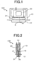
- FIG. 1 is a schematic front view showing an ink-jet head 100
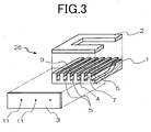
- FIG. 2 is a schematic cross-sectional view thereof
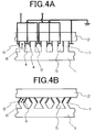
- FIG. 3 is an exploded diagram showing a periphery of a driving part for generating a pressure necessary for discharge of ink and of a nozzle part from which ink is finally discharged.
- a plurality of grooves 5 are arranged in parallel with each other, and the grooves 5 are separated from each other by side walls 7.
- One end of each of the grooves 5 in a longitudinal direction thereof extends to one end surface of the piezoelectric ceramic plate 1.
- the other end thereof does not extend to the other end surface of the piezoelectric ceramic plate 1, and a depth of each of the grooves 5 gradually decreases.
- an electrode 4 and an electrode 9 for driving electric field application in the longitudinal direction.
- a head chip 26 which is joined to an ink chamber plate 2.
- a nozzle plate 3 is joined to the end surface at which the grooves 5 of a joined body of the piezoelectric ceramic plate 1 and the ink chamber plate 2 are opened.
- a nozzle plate 3 is joined to the end surface at which the grooves 5 of a joined body of the piezoelectric ceramic plate 1 and the ink chamber plate 2 are opened.
- a nozzle plate 3 is joined to the end surface at which the grooves 5 of a joined body of the piezoelectric ceramic plate 1 and the ink chamber plate 2 are opened.
- a nozzle plate 3 is joined to the end surface at which the grooves 5 of a joined body of the piezoelectric ceramic plate 1 and the ink chamber plate 2 are opened.
- a nozzle plate 3 is joined to the end surface at which the grooves 5 of a joined body of the piezoelectric ceramic plate 1 and the ink chamber plate 2 are opened.
- a nozzle plate 3 is joined to the end surface at which the grooves
- an ink flow path 21 for supplying ink to each of the grooves 5 is fixed, an ink inlet 41 for introducing ink is formed at a central portion of the ink flow path 21, and the ink inlet 41 is connected to a pressure absorbing unit 20 for absorbing a pressure fluctuation caused during a printing operation.
- FIGS. 20A to 20C are diagrams each showing a discharge signal waveform of the ink-jet head 100 according to a related art.
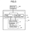
- FIGS. 4A and 4B are cross-sectional diagrams each showing a wiring state of the electrodes of the ink-jet head 100.
- FIG. 20A is a diagram showing a discharge signal waveform in a case of discharging ink with a volume of one droplet according to the related art.
- FIG. 20B is a diagram showing a discharge signal waveform in a case of discharging ink with a volume of two droplets according to the related art.
- FIG. 20C is a diagram showing a discharge signal waveform in a case of discharging ink with a volume of three droplets according to the related art.
- FIG. 4A is a cross-sectional diagram of the ink-jet head when the ink-jet head is not driven
- FIG. 4B is a cross-sectional diagram of the ink-jet head when the ink-jet head is driven.
- the arrow 6 indicates a polarization direction.
- the ink-jet head 100 has an electrode structure in which the electrode 4 formed in each of the grooves 5 is a common electrode with a ground potential, and the electrodes 9 sandwiching the electrode 4 are each applied with a drive pulse from an outside.
- a positive electric field pulse which is represented by a discharge signal waveform for the ink with the volume of one droplet as shown in FIG. 20A
- the side walls 7 are each deformed due to a potential difference between the electrode 9 and the electrode 4 as shown in FIG. 4B .
- the side walls 7 are each deformed for a time T1b during which the positive electric field is applied to each of the electrodes 9.
- the side walls 7 each return to a state shown in FIG. 4A again.
- the time T1b is set as a most efficient time at which the discharge speed is increased as being apparent from FIG. 19 showing a relation between an electric field application time and a discharge speed. Due to the deformation of each of the side walls 7, the ink filled in each of the grooves 5 changes in pressure, whereby one ink droplet is allowed to fly from the nozzle hole 11.
- the positive electric field is applied a plurality of times so as to change a discharge volume of the ink flying onto the recording medium from each of the nozzle holes 11, thereby making it possible to perform gradation expression.
- the positive pulse (application time T2b) is operated before the positive electric field pulse (application time T1b) during an interval of a time T4b as shown in FIG. 20B .
- the positive electric field pulse (application time T3b) is operated before the positive electric field pulses (application times T1b and T2b) as shown in FIG. 20C .
- the ink with the volume of three droplets can be allowed to fly from the nozzle hole 11.
- the times for application of the positive electric field pulse with a predetermined voltage for deforming and operating the actuator formed of each of the side walls 7 to allow the ink to fly from each of the nozzle holes 11 are set to be equal to each of the rest times between pulse application operations, during which the actuator is not driven. As a result, the ink can be discharged with efficiency.
- FIG. 21 shows a relation between a fluctuation of a pressure P of each of the nozzle holes 11 and a drive voltage between the electrode 4 and the electrode 9.
- a time T1 corresponds to the time T1b of FIG. 19 .
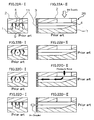
- FIGS. 22A-I to 22D-II each schematically show a behavior of each of the side walls 7, a change in pressure of each of the nozzle holes 11, and the ink flow path.
- FIGS. 22A-I to 22D-II are cross-sectional diagrams each showing the nozzle plate 3 and the head chip 26.
- FIGS. 22A-I, 22B-I, 22C-I, and 22D-I each show the nozzle plate 3 and the head chip 26 viewed from an axial direction of the nozzle holes 11, and FIGS. 22A-II, 22B-II, 22C-II, and 22D-II are side views thereof.
- FIGS. 22A-I and 22A-II each show a state obtained before application of the drive pulse in FIG. 21
- FIGS. 22B-I and 22B-II each show a state at a time (time t11) when the drive pulse application is started in FIG. 21
- FIGS. 22C-I to 22D-II each show a state at a time (time t12) when the drive pulse application is finished in FIG. 21 .
- US 6,059,393 discloses a driving method for an ink ejection device in which two droplets are ejected successively at different speeds so that the two droplets merge before individually impinging against a sheet of paper.
- a first pulse signal is applied to an actuator to thereby eject a first droplet at a first speed and thereafter a second pulse signal is applied thereto to thereby eject a second droplet at a second speed faster than the first speed.
- the two droplets are merged during flying and the merged droplet forms a print dot on the sheet of paper.
- the print dot obtained when the flight time was shorter than 100 ⁇ s is larger by 20% than that obtained when the flight time was longer than 100 ⁇ s.
- the flight time can be adjusted by changing a time difference between the falling edges of the first and second pulse signals.
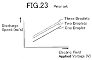
- an object of the present invention to provide a method of driving an ink-jet head for improving an impact position accuracy of ink droplets by eliminating a difference in discharge speed caused due to a difference in volume of ink corresponding to one droplet, two droplets, and three droplets for performing gradation expression, an ink-jet head, and an ink-jet recording apparatus.
- control means sets the duration of the initial drive pulse to a range of values from 1/1.7 to 1/2.5 of the duration of the final drive pulse.
- control means sets the duration of the initial drive pulse to a range of values from 1.35 to 1.75 times the duration of the final drive pulse.
- an ink-jet head as defined in claim 6.
- an ink-jet recording apparatus including: the ink-jet head according to the third aspect of the present invention; an ink supply part for supplying ink to the ink-jet head; and recording medium transport means which transports a recording medium onto which ink is discharged from the ink-jet head.
- a signal waveform of the final drive pulse for allowing ink with an appropriate volume of n-1 droplets (n is an integer equal to or larger than 2) to fly is synchronized with a signal waveform of the final drive pulse for allowing ink with an appropriate volume of n droplets to fly.
- the control means varies the duration of the final drive pulse to be finally applied from the duration of the initial drive pulse to be applied once or more before the final drive pulse, among the drive pulses to be generated a plurality of times with the predetermined voltage.
- the total of the rest time and the duration of the initial drive pulse is equal to twice the duration of the final drive pulse, and the duration of the initial drive pulse is set to between 1/1.5 and 1/2.9 of the duration of the final drive pulse or between 1.2 times and 1.8 times as much as the duration of the final drive pulse.
- an ink-jet head and an ink-jet type recording apparatus for eliminating a difference in discharge speed for ink droplets, which is caused when the ink with the volume of a plurality of droplets, that is, one droplet, two droplets, and three droplets in the case of performing the gradation expression, and for improving an impact position accuracy of ink droplets to thereby provide an excellent image quality.
- FIG. 1 is a front view showing an entirety of an ink-jet head 100 according to an embodiment of the present invention.
- FIG. 2 is a schematic cross-sectional diagram showing the ink-jet head 100 according to the embodiment of the present invention.
- FIG. 3 is an exploded diagram showing a periphery of a discharge pressure generating part of the ink-jet head 100 according to the embodiment of the present invention.
- the ink-jet head 100 includes a head chip 26, an ink flow path 21 provided on one side of the head chip 26, a drive circuit substrate 14 on which a drive circuit for driving the head chip 26 and the like are mounted, and a pressure absorbing unit 20 for absorbing a pressure change in the head chip 26.
- Those components are each fixed to a base 13.
- a piezoelectric ceramic plate 1 constituting the head chip 26 a plurality of grooves 5 which communicate with nozzle holes 11 are arranged in parallel with each other, and the grooves 5 are separated from each other by side walls 7.
- each of the grooves 5 in a longitudinal direction extends to one end surface of the piezoelectric ceramic plate 1, and the other end thereof does not extend to the other end surface of the piezoelectric ceramic plate 1, and a depth of each of the grooves 5 gradually decreases.
- an electrode 4 and an electrode 9 for driving electric field application in the longitudinal direction on an opening side of each of the grooves 5 are formed on both sides of the side walls 7 in a width direction of each of the grooves 5.
- the grooves 5 formed in the piezoelectric ceramic plate 1 are formed by, for example, a disc-like die cutter, and a portion of each of the grooves 5 whose depth gradually decreases is to be formed in a shape of the die cutter.
- the electrode 4 and the electrode 9 to be formed in each of the grooves 5 are formed by, for example, known deposition from an oblique direction.
- the electrode 4 and the electrode 9 provided on the opening side of the side walls 7 on both sides of each of the grooves 5 are each connected to one end of a flexible substrate 19.
- the other end of the flexible substrate 19 is connected to a drive circuit (not shown) formed on the drive circuit substrate 14.
- the electrode 4 and the electrode 9 are electrically connected to the drive circuit.
- the opening side of each of the grooves 5 of the piezoelectric ceramic plate 1 is connected to an ink chamber plate 2.
- the ink chamber plate 2 can be formed of a ceramic plate, a metal plate, or the like. However, when deformation of the ink chamber plate 2 after being joined to the piezoelectric ceramic plate 1 is taken into consideration, it is preferable to use a ceramic plate having a thermal expansion coefficient approximate to that of the piezoelectric plate 1.
- a nozzle plate 3 is joined to the end surface at which the grooves 5 of a joined body of the piezoelectric ceramic plate 1 and the ink chamber plate 2.
- the nozzle holes 11 are formed at positions opposite to every other groove 5 of the nozzle plate 3, whereby the nozzle holes 11 are connected to the grooves 5.
- the nozzle plate 3 has an area larger than that of the end surface at which the grooves 5 of the joined body of the piezoelectric ceramic plate 1 and the ink chamber plate 2 are opened.
- the nozzle plate 3 is obtained by forming the nozzle holes 11 in a polyimide film or the like by employment of, for example, an excimer laser device.
- a water-repellent film (not shown) having water repellency for preventing adhesion of ink or the like.
- a head cap 12 for supporting the nozzle plate 3 is joined.
- the head cap 12 is joined to an outside of the end surface of the joined body of the nozzle plate 3, thereby stably holding the nozzle plate 3.
- the ink flow path 21 for supplying ink to each of the grooves 5 is fixed onto the ink chamber plate 2, an ink inlet 41 for introducing ink is formed at a central portion of the ink flow path 21, and the ink inlet 41 is connected to the pressure absorbing unit 20 for absorbing the pressure fluctuation caused during a printing operation.
- the pressure absorbing unit 20 is filled with the ink from an ink tank (not shown) at the time of initial filling or the like, and the ink is introduced into the ink flow path 21.
- the grooves 5 are each filled with the ink.
- the ink-j et head 100 of the embodiment of the present invention includes the head chip 26 having the electrode 4 and the electrode 9, and the drive circuit substrate 14 connected to the head chip 26 via the flexible substrate 19.
- the drive circuit substrate 14 is also connected to an ink-jet head drive control part 110 including a head control part 111 and an image data processing part 112.
- An ink-jet recording apparatus 120 including the ink-jet head 100 and the ink-jet head drive control part 110 is connected to a personal computer 200 or the like via a predetermined interface.
- the ink-jet recording apparatus 120 also includes an ink supply part (not shown) for supplying ink to the ink-jet head 100, and a recording medium transport part (not shown) for transporting the recording medium on which the ink is discharged from the ink-jet head 100.
- the drive circuit substrate 14 (application means) is formed of a circuit including a switching element for performing on/off control of the voltage to be applied to each of the electrode 4 and the electrode 9, and deforms and operates the actuator formed of each of the side walls 7, thereby applying the predetermined voltage for allowing ink to fly from each of the nozzle holes 11 to the electrode 4 and the electrode 9 while a rest time during which the actuator is not operated is provided.
- the head control part 111 supplies electrode applied voltage and control signals for performing on/off control for the switching element or the like to the drive circuit substrate 14, and applies a drive pulse with a predetermined voltage to each of the electrode 4 and the electrode 9, thereby performing control of starting and stopping of the discharge of ink in each of the nozzles 11.
- the image data processing part 112 creates image data corresponding to each of the nozzle holes 11 based on information inputted from the personal computer 200.
- the image data processing part 112 outputs binary signals for setting a timing for applying the voltage to each of the electrode 4 and the electrode 9 based on the created image data, thereby generating the drive pulse to be applied to each of the electrode 4 and the electrode 9 a plurality of times to perform control of changing the volume of ink droplets reaching the recording medium.
- the image data processing part 112 outputs signals for instructing application or stopping the application of the voltage corresponding to each of the nozzle holes 11 based on the image data consisting of binary data (0 or 1).
- the image data processing part 112 outputs signals for instructing the number of times of generation of the drive pulses for four types of discharge volumes (0 droplets, one droplet, two droplets, and three droplets) corresponding to each of the nozzle holes 11, based on image data consisting of quaternary data (0, 1, 2, and 3).
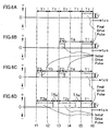
- FIGS. 6A to 6D are diagrams each showing a discharge signal waveform (drive pulse waveform of each of electrode 4 and electrode 9) of the ink-jet head 100 according to the embodiment of the present invention.
- FIGS. 4A and 4B are cross-sectional diagrams each showing a wiring state of the electrodes of the ink-jet head 100.
- FIG. 6A is a diagram showing a discharge signal waveform in a case of discharging ink with a volume of one droplet according to the embodiment of the present invention.
- FIG. 6B is a diagram showing a discharge signal waveform in a case of discharging ink with a volume of two droplets according to the embodiment of the present invention.
- FIG. 6C is a diagram showing a discharge signal waveform in a case of discharging ink with a volume of three droplets according to the embodiment of the present invention.
- FIG. 4A is a cross-sectional diagram of the ink-jet head when the ink-jet head is not driven
- FIG. 4B is a cross-sectional diagram of the ink-jet head when the ink-jet head is driven.
- the arrow 6 indicates a polarization direction. When an electric field is applied to each of the electrode 4 and the electrode 9 which sandwich the side wall 7, each of the side walls 7 deforms in a desired direction.
- the ink-jet head 100 has an electrode structure in which the electrode 4 formed in each of the grooves 5 is a common electrode with a ground potential, and the electrodes 9 sandwiching the electrode 4 is applied with output signals from the outside.
- a positive electric field pulse (drive pulse) shown in FIG. 6A is applied to each of the electrodes 9, the side walls 7 are each deformed due to a potential difference between the electrode 9 and the electrode 4 as shown in FIG. 4B .
- the side walls 7 are each deformed for a time T1 during which the positive electric field is applied to each of the electrodes 9, and when the potential of the electrode 9 becomes 0 after the elapse of the time T1, the side walls 7 each return to a state shown in FIG. 4A again.
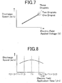
- the time T1 is set to the most efficient time at which the discharge speed is increased as being apparent from FIG. 8 showing the relation between the electric field application time and the discharge speed.
- the positive electric field pulse with the duration of the time T1, at which an efficient discharge speed is obtained, is referred to as final drive pulse. Due to the deformation of each of the side walls 7, the ink filled in each of the grooves 5 changes in pressure, whereby one ink droplet is allowed to fly from each of the nozzle holes 11.
- a positive electric field pulse with a time T2 shorter than the time T1 is applied before the final drive pulse, as shown in FIG. 6B , with an interval of a time T4.
- the ink with a volume of two droplets is allowed to fly from each of the nozzle holes 11.
- a positive electric field pulse with an application time T3 which is shorter than the duration T1 of the final drive pulse and is the same as the time T2 is operated before the pulse with the time T1 and the pulse with the time T2 of the positive electric field shown in FIG. 20C , with an interval of a time T5. Then, the ink with the volume of three droplets can be allowed to fly from each of the nozzle holes 11.
- the positive drive pulses with the time T2 and the time T3, which are shorter than the final drive pulse with the time T1 are each referred to as initial drive pulse.
- the initial drive pulse has an application time shorter than that of the final drive pulse, but enables discharge of the same volume of ink droplets.
- the ink droplets discharged by the initial drive pulse with the time T2 or by the initial drive pulse with the time T3 are continuously discharged in a short period of time. Accordingly, the ink droplets are combined into large droplets during the flight between each of the nozzle holes 11 and the recording medium to be impacted on the recording medium, thereby enabling the gradation expression.
- start-up times t1, t3, and t5 of each of the initial drive pulse and the final drive pulse are set to be constant with a cycle twice as long as the time T1.
- the plurality of nozzle holes 11 from which the ink should be discharged at the same timing are controlled so that the application times t5 of the final drive pulses match (synchronized) with each other.
- FIGS. 6A to 6C each show a drive waveform in a case of discharging ink with an amount of one droplet, two droplets, and three droplets from a given nozzle hole 11, respectively.
- FIGS. 6A to 6C each show a timing for discharging ink droplets with the amount of one droplet, two droplets, and three droplets from a plurality of different nozzle holes 11 at which recording positions are linearly arranged, assuming that time axes of the FIGS. 6A to 6C match with each other.
- T1-T2 a time (T1-T2), by which the time of the initial drive pulse becomes shorter than that of the final drive pulse, is added to the rest time, which is set as a new rest time.
- the rest time and the drive pulse application time each correspond to the constant time T1 (T1b to T5b of FIGS.
- the total of the application times and the rest times for the drive pulse corresponding to each discharge is twice as much as the time T1 and is constant.
- the total of the application times of the initial drive pulse and the rest times is set to be twice as much as the time T1 and to be constant, thereby making it possible to continuously discharge ink with efficiency as in the conventional case.
- the time T1 is 12 ⁇ sec
- the time T2 and the time T3 are each 6 ⁇ sec
- the time T4 and the time T5 are each 18 ⁇ sec.
- the application times T2a and T3a of the initial drive pulse can be set to be longer than the application time T1 of the final drive pulse.
- FIG. 8 also by setting the times T2a and T3a of the initial drive pulse to be longer than the time T1 of the final drive pulse, a lower discharge speed can be achieved.
- the rest time becomes shorter by that amount.
- the total of the drive pulses and the rest times can be set to be twice as much as the time T1 and to be constant, thereby making it possible to discharge ink with efficiency as in the conventional case.
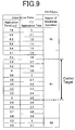
- the difference in discharge speed among one droplet (small ink droplet), two droplets (medium ink droplet), and three droplets (large ink droplet) falls within a variation range of 0.8 m/s as shown in FIG. 11 .
- the value obtained by dividing T1 by the application time represents a value obtained by dividing the duration of the final drive pulse T1 by the duration (application time) of the initial drive pulse.
- the range from 1. 5 to 2. 9 represents a range in which the duration of the initial drive pulse is set from 1/1.5 to 1/2.9 of the duration of the final drive pulse.
- FIG. 11 shows results of measurement of the relation between the applied voltage and the discharge speed at a certain set time in the range R1 by changing the amount of ink.
- the variation value of 0.8 m/s is a value empirically obtained as a value for holding the image quality of the recording results in a desired range in the ink-j et head having a characteristic of an ink discharge speed of about 5 m/s. When the value falls within the range, a large number of subjects visually probably consider the image quality excellent.
- the range set as a control target is a range which is considered to be set as a design value by taking ambient conditions and manufacturing conditions into consideration. Under those conditions, a range of the application time of 4.5 ⁇ m to 3.0 ⁇ m (range in which duration of initial drive pulse is set from 1/1. 7 to 1/2. 5 of duration of final dive pulse) is considered to be suitable as the control target.
- the time of the initial drive pulse is set to be equal to or larger than 5.4 ⁇ m (value obtained by dividing T1 by application time: 1.4 or smaller) (region R2), as shown in FIG. 12 , the discharge speed for each of the ink droplets with the amounts corresponding to two droplets and three droplets is larger than the discharge speed for the amount of ink corresponding to one droplet, and the difference in discharge speed is 0.8 m/s or larger.
- the time of the initial drive pulse is set to be equal to or smaller than 2. 5 ⁇ m (value obtained by dividing T1 by application time: 3 or larger) (region R3), as shown in FIG.
- the discharge speed for each of the ink droplets with the amounts of ink corresponding to two droplets and three droplets is smaller than the discharge speed for the amount of ink corresponding to one droplet, and the difference in discharge speed is 0.8 m/s or larger.
- FIG. 10 shows results of an experiment for confirming how the ink is discharged when the application time of the initial drive pulse is changed within a range equal to or larger than the time T1, by using the same ink-jet head 100.
- the difference in discharge speed among one droplet (small ink droplet), two droplets (medium ink droplet), and three droplets (large ink droplet) falls within the variation range of 0.8 m/s as shown in FIG. 11 .
- a range of the application time from 10.3 ⁇ m (value obtained by dividing application time by T1: 1.35) to 13.3 ⁇ m (value obtained by dividing application time by T1: 1. 75) is considered to be suitable as the control target.
- the duration of the initial drive pulse is set to be 1.2 times to 1. 8 times as much as the duration of the final drive pulse, thereby obtaining an excellent image quality.
- the range from 1.35 times to 1.75 times seems to be suitable as the control target.
- the time of the initial drive pulse is set to be equal to or smaller than 8.7 ⁇ s (value obtained by dividing application time by T1: 1.15 or smaller) (region R2), as shown in FIG. 12 , the discharge speed for each of the ink droplets with the amounts corresponding to two droplets and three droplets is larger than the discharge speed for the amount of ink corresponding to one droplet, and the difference in discharge speed is 0.8 m/s or larger.
- the time of the initial drive pulse is set to be equal to or larger than 14.1 ⁇ s (value obtained by dividing application time by T1: 1.85 or larger) (region R3), as shown in FIG.
- the discharge speed for each of the ink droplets with the amounts of ink corresponding to two droplets and three droplets is smaller than the discharge speed for the amount of ink corresponding to one droplet, and the difference in discharge speed is 0.8 m/s or larger.
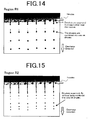
- FIG. 14 is a photograph showing a discharge state, which is taken under conditions of the region R1
- FIG. 15 is a photograph showing a discharge state, which is taken under conditions of the region R2.
- the ink with the amount corresponding to three droplets is repeatedly discharged by the application of three drive pulses.
- the ink is discharged under the conditions of the region R1 shown in FIG.
- first to third droplets are separated from each other near the nozzles (in the photograph, the first droplet and the second droplet are combined into one droplet, and the third droplet is separated to a small extent), but three ink droplets are combined into one ink droplet immediately after being discharged and separated from each of the nozzle holes 11.
- the three ink droplets separately fly without being combined into one ink droplet as taken from a photograph. In this case, it is difficult for the ink adhered to the medium to form a well-defined circular shape.
- FIGS. 14 and 15 are taken in a state where 8000 ink droplets are discharged per second at an initial speed of ink droplets of about 5 m/s.
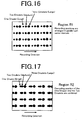
- FIGS. 16 and 17 each show recording results obtained after repeatedly discharging the ink with the amount of one droplet, two droplets, and three droplets onto the recording medium from four nozzle holes 11 while the ink-jet head 100 is moved.
- FIG. 16 shows the recording results when the drive voltage is controlled under the conditions of the region R1
- FIG. 17 shows the recording results when the drive voltage is controlled under the conditions of the region R2.
- the discharge speed is set to be the same irrespective of the amount of ink, so recording positions are arranged in parallel with each other with the same intervals in a recording direction.
- the discharge speed for the ink droplet corresponding to one droplet is lower than that for the ink droplets corresponding to two droplets and three droplets as shown in FIG. 12 . Accordingly, the recording position of the ink with the amount of one droplet and the recording position of the ink with the amount of two droplets are combined with each other. Note that in the recording of each of FIGS. 16 and 17 , an interval between the ink-jet head 100 and the recording medium is 2 mm, and a movement speed of the ink-jet head 100 is 1 m/s.
- the discharge as shown in each of FIGS. 6A to 6C and the discharge shown in each of FIGS. 6A and 6D are continuously performed in an arbitrary combination thereof based on gradation data, thereby making it possible to discharge ink droplets with different amounts to perform arbitrary gradation expression on the recording medium.
- the ink discharge speeds at the time of discharging the ink with the amounts of two droplets and three droplets are equal to each other as compared with the discharge speed at the time of discharging one droplet. Accordingly, there can be provided a printed material with an excellent quality with no difference in impact positions of ink droplets when the printing is performed using an ink-jet printer.
- the discharge of the ink with the amount of one droplet, two droplets, and three droplets is described above.
- an upper limit of the ink droplet amount is not particularly limited. Rectangular waves with the electric field application times of T1, T2, and T3 are used as the signal applied voltage V used in the embodiment of the present invention.
- the waveform and the signal applied voltage which smooth the start-up may be gradually changed during the electric field application time, and the waveform is not limited to a particular waveform.
Landscapes
- Particle Formation And Scattering Control In Inkjet Printers (AREA)
Claims (8)
- Ansteuerverfahren eines Tintenstrahlkopfs,
wobei der Tintenstrahlkopf enthält:mehrere Seitenwände (7), die jeweils aus einem Stellglied gebildet sind, das als Reaktion auf eine angelegte Spannung verformt und betrieben wird;mehrere Rillen (5), die parallel zueinander zwischen den mehreren Seitenwänden (7) derart angeordnet sind, dass sie mit Düsen (11) in Verbindung stehen;einen Tintenströmungspfad (21) zum Zuleiten von Tinte zu jeder der mehreren Rillen (5);eine Elektrode (4, 9), die an jeder der mehreren Seitenwände (7) vorgesehen ist;ein Anlegungsmittel, das einen Ansteuerimpuls mit einer vorbestimmten Spannung zum Verformen und Betreiben des Stellgliedes anlegt, so dass Tinte von den Düsen (11) zu der Elektrode (4, 9) fliegen kann, wobei eine Ruheperiode vorgesehen ist, in der ein Betrieb des Stellgliedes verhindert wird; undein Steuermittel (110), das den Ansteuerimpuls, der an die Elektrode (4, 9) durch das Anlegungsmittel angelegt wird, mehrere Male erzeugt, um ein Volumen von Tintentröpfchen zu ändern, die ein Aufzeichnungsmedium erreichen,wobei das Verfahren umfasst:das Einstellen durch das Steuermittel (110), unter den erzeugten Ansteuerimpulsen, einer Dauer eines abschließenden Ansteuerimpulses, der abschließend an die Elektrode (4, 9) angelegt wird, um Tinte auszustoßen, und einer Dauer eines anfänglichen Ansteuerimpulses, der an die Elektrode (4, 9) angelegt wird, um Tinte auszustoßen, wobei der anfängliche Ansteuerimpuls mindestens einmal vor dem abschließenden Ansteuerimpuls angelegt wird; und gekennzeichnet durchdas Einstellen der Dauer des anfänglichen Ansteuerimpulses auf einen Bereich von Werten von 1/1,5 bis 1/2,9 der Dauer des abschließenden Ansteuerimpulses;wobei die anfänglichen und abschließenden Ansteuerimpulse derart angelegt werden, dass mehrere Tintentröpfchen derart ausgestoßen werden, dass eine Differenz in der Abgabegeschwindigkeit zwischen den Tintentröpfchen verringert wird, wobei die Ruhezeit die Zeit zwischen dem Ende des letzten angelegten anfänglichen Ansteuerimpulses und dem Start des abschließenden Ansteuerimpulses ist und die Summe der Ruhezeit und der Dauer des anfänglichen Ansteuerimpulses gleich der zweifachen Dauer des abschließenden Ansteuerimpulses ist. - Ansteuerverfahren eines Tintenstrahlkopfs nach Anspruch 1, wobei das Steuermittel (110) die Dauer des anfänglichen Ansteuerimpulses auf einen Bereich von Werten von 1/1,7 bis 1/2,5 der Dauer des abschließenden Ansteuerimpulses einstellt.
- Ansteuerverfahren eines Tintenstrahlkopfs,
wobei der Tintenstrahlkopf enthält:mehrere Seitenwände (7), die jeweils aus einem Stellglied gebildet sind, das als Reaktion auf eine angelegte Spannung verformt und betrieben wird;mehrere Rillen (5), die parallel zueinander zwischen den mehreren Seitenwänden (7) derart angeordnet sind, dass sie mit Düsen (11) in Verbindung stehen;einen Tintenströmungspfad (21) zum Zuleiten von Tinte zu jeder der mehreren Rillen (5);eine Elektrode (4, 9), die an jeder der mehreren Seitenwände (7) vorgesehen ist;ein Anlegungsmittel, das einen Ansteuerimpuls mit einer vorbestimmten Spannung zum Verformen und Betreiben des Stellgliedes anlegt, so dass Tinte von den Düsen (11) zu der Elektrode (4, 9) fliegen kann, wobei eine Ruheperiode vorgesehen ist, in der ein Betrieb des Stellgliedes verhindert wird; undein Steuermittel (110), das den Ansteuerimpuls, der an die Elektrode (4, 9) durch das Anlegungsmittel angelegt wird, mehrere Male erzeugt, um ein Volumen von Tintentröpfchen zu ändern, die ein Aufzeichnungsmedium erreichen,wobei das Verfahren umfasst:das Einstellen durch das Steuermittel (110), unter den erzeugten Ansteuerimpulsen, einer Dauer eines abschließenden Ansteuerimpulses, der abschließend an die Elektrode (4, 9) angelegt wird, um Tinte auszustoßen, und einer Dauer eines anfänglichen Ansteuerimpulses, der an die Elektrode (4, 9) angelegt wird, um Tinte auszustoßen, wobei der anfängliche Ansteuerimpuls mindestens einmal vor dem abschließenden Ansteuerimpuls angelegt wird; und gekennzeichnet durchdas Einstellen der Dauer des anfänglichen Ansteuerimpulses auf einen Bereich von Werten des 1,2- bis 1,8-Fachen der Dauer des abschließenden Ansteuerimpulses;wobei die anfänglichen und abschließenden Ansteuerimpulse derart angelegt werden, dass mehrere Tintentröpfchen derart ausgestoßen werden, dass eine Differenz in der Abgabegeschwindigkeit zwischen den Tintentröpfchen verringert wird, wobei die Ruhezeit die Zeit zwischen dem Ende des letzten angelegten anfänglichen Ansteuerimpulses und dem Start des abschließenden Ansteuerimpulses ist und die Summe der Ruhezeit und der Dauer des anfänglichen Ansteuerimpulses gleich der zweifachen Dauer des abschließenden Ansteuerimpulses ist. - Ansteuerverfahren eines Tintenstrahlkopfs nach Anspruch 3, wobei das Steuermittel (110) die Dauer des anfänglichen Ansteuerimpulses auf einen Bereich von Werten vom 1,35- bis 1,75-Fachen der Dauer des abschließenden Ansteuerimpulses einstellt.
- Ansteuerverfahren eines Tintenstrahlkopfs nach einem der Ansprüche 1 bis 4, wobei der anfängliche Ansteuerimpuls mindestens zweimal vor dem abschließenden Ansteuerimpuls angelegt wird und die Zeit zwischen dem Ende eines als ersten angelegten anfänglichen Ansteuerimpulses und dem Start eines als zweiten angelegten anfänglichen Ansteuerimpulses gleich der Ruhezeit ist.
- Tintenstrahlkopf, enthaltend:mehrere Seitenwände (7), die jeweils aus einem Stellglied gebildet sind, das als Reaktion auf eine angelegte Spannung verformt und betrieben wird;mehrere Rillen (5), die parallel zueinander zwischen den mehreren Seitenwänden (7) derart angeordnet sind, dass sie mit Düsen (11) in Verbindung stehen;einen Tintenströmungspfad (21) zum Zuleiten von Tinte zu jeder der mehreren Rillen (5);eine Elektrode (4, 9), die an jeder der mehreren Seitenwände (7) vorgesehen ist;ein Anlegungsmittel, das zum Anlegen eines Ansteuerimpulses mit einer vorbestimmten Spannung zum Verformen und Betreiben des Stellgliedes ausgebildet ist, so dass Tinte von den Düsen (11) zu der Elektrode (4, 9) fliegen kann, wobei eine Ruheperiode vorgesehen ist, in der ein Betrieb des Stellgliedes verhindert wird; undein Steuermittel (110), das zum mehrmaligen Erzeugen des Ansteuerimpulses ausgebildet ist, der an die Elektrode (4, 9) durch das Anlegungsmittel angelegt wird, um ein Volumen von Tintentröpfchen zu ändern, die ein Aufzeichnungsmedium erreichen,wobei:das Steuermittel (110) zum Einstellen einer Dauer eines abschließenden Ansteuerimpulses, der abschließend an die Elektrode (4, 9) angelegt wird, um Tinte auszustoßen, und einer Dauer eines anfänglichen Ansteuerimpulses, der an die Elektrode (4, 9) angelegt wird, um Tinte auszustoßen, unter den erzeugten Ansteuerimpulsen ausgebildet ist, wobei das Steuermittel (110) zum Erzeugen des anfänglichen Ansteuerimpulses mindestens einmal vor dem abschließenden Ansteuerimpuls ausgebildet ist; dadurch gekennzeichnet, dassdas Steuermittel (110) zum Einstellen der Dauer des anfänglichen Ansteuerimpulses auf einen Bereich von Werten von 1/1,5 bis 1/2,9 der Dauer des abschließenden Ansteuerimpulses oder auf einen Bereich von Werten vom 1,2- bis 1,8-Fachen der Dauer des abschließenden Ansteuerimpulses ausgebildet ist; unddas Anlegungsmittel zum derartigen Anlegen der anfänglichen und abschließenden Ansteuerimpulse ausgebildet ist, dass mehrere Tintentröpfchen derart ausgestoßen werden, dass eine Differenz in der Abgabegeschwindigkeit zwischen den Tintentröpfchen verringert wird, wobei die Ruhezeit die Zeit zwischen dem Ende des letzten angelegten anfänglichen Ansteuerimpulses und dem Start des abschließenden Ansteuerimpulses ist, und das Steuermittel (110) zum derartigen Erzeugen der Ansteuerimpulse ausgebildet ist, dass die Summe der Ruhezeit und der Dauer des anfänglichen Ansteuerimpulses gleich der zweifachen Dauer des abschließenden Ansteuerimpulses ist.
- Tintenstrahlkopf nach Anspruch 6, wobei das Steuermittel (110) zum Erzeugen des anfänglichen Ansteuerimpulses mindestens zweimal vor dem abschließenden Ansteuerimpuls ausgebildet ist und die Zeit zwischen dem Ende eines als ersten angelegten anfänglichen Ansteuerimpulses und dem Start eines als zweiten angelegten anfänglichen Ansteuerimpulses gleich der Ruhezeit ist.
- Tintenstrahl-Aufzeichnungsgerät, umfassend:einen Tintenstrahlkopf nach Anspruch 6 oder Anspruch 7;ein Tintenzuleitungsteil zum Zuleiten von Tinte zum Tintenstrahlkopf; undein Aufzeichnungsmedium-Transportmittel, das ein Aufzeichnungsmedium transportiert, auf das Tinte vom Tintenstrahlkopf abgegeben wird.
Applications Claiming Priority (1)
| Application Number | Priority Date | Filing Date | Title |
|---|---|---|---|
| JP2007115928A JP4966084B2 (ja) | 2007-04-25 | 2007-04-25 | インクジェットヘッドの駆動方法、インクジェットヘッドおよびインクジェット記録装置 |
Publications (2)
| Publication Number | Publication Date |
|---|---|
| EP1985451A1 EP1985451A1 (de) | 2008-10-29 |
| EP1985451B1 true EP1985451B1 (de) | 2012-02-08 |
Family
ID=39591253
Family Applications (1)
| Application Number | Title | Priority Date | Filing Date |
|---|---|---|---|
| EP08251516A Ceased EP1985451B1 (de) | 2007-04-25 | 2008-04-24 | Ansteuerverfahren eines Tintenstrahlkopfes, Tintenstrahlkopf und Tintenstrahl-Aufzeichnungsgerät |
Country Status (3)
| Country | Link |
|---|---|
| US (1) | US8057002B2 (de) |
| EP (1) | EP1985451B1 (de) |
| JP (1) | JP4966084B2 (de) |
Families Citing this family (6)
| Publication number | Priority date | Publication date | Assignee | Title |
|---|---|---|---|---|
| JP2010158864A (ja) * | 2009-01-09 | 2010-07-22 | Sii Printek Inc | 液体噴射ヘッドチップ及びその製造方法、並びに液体噴射ヘッド及び液体噴射記録装置 |
| JP2011224839A (ja) * | 2010-04-16 | 2011-11-10 | Sii Printek Inc | 液体噴射ヘッドおよび液体噴射記録装置 |
| US8911046B2 (en) * | 2013-03-15 | 2014-12-16 | Fujifilm Dimatix, Inc. | Method, apparatus, and system to provide droplets with consistent arrival time on a substrate |
| JP6598431B2 (ja) * | 2014-06-06 | 2019-10-30 | エスアイアイ・プリンテック株式会社 | 液体噴射ヘッド及び液体噴射装置 |
| JP6598696B2 (ja) | 2016-01-29 | 2019-10-30 | 東芝テック株式会社 | インクジェットヘッド及びインクジェットプリンタ |
| US11440315B2 (en) | 2016-08-31 | 2022-09-13 | Konica Minolta, Inc. | Ink jet recording apparatus and ink jet recording method |
Family Cites Families (15)
| Publication number | Priority date | Publication date | Assignee | Title |
|---|---|---|---|---|
| DE69634013T2 (de) | 1995-05-26 | 2005-12-15 | SurModics, Inc., Eden Prairie | Verfahren und implantierbarer gegenstand zur förderung der endothelialisierung |
| JPH0966603A (ja) | 1995-08-31 | 1997-03-11 | Brother Ind Ltd | インク噴射装置の駆動方法 |
| EP1124590B1 (de) | 1997-04-03 | 2009-06-17 | California Institute Of Technology | Enzym-vermittelte modifizierung von fibrin für gewebeaufbau |
| JP4491907B2 (ja) | 2000-04-26 | 2010-06-30 | ブラザー工業株式会社 | インク滴噴射方法およびその制御装置並びに記憶媒体 |
| US6428579B1 (en) | 1998-07-01 | 2002-08-06 | Brown University Research Foundation | Implantable prosthetic devices coated with bioactive molecules |
| US6554857B1 (en) | 1999-07-20 | 2003-04-29 | Medtronic, Inc | Transmural concentric multilayer ingrowth matrix within well-defined porosity |
| JP4000749B2 (ja) * | 2000-04-26 | 2007-10-31 | コニカミノルタホールディングス株式会社 | インク滴噴射装置 |
| ES2186484B1 (es) | 2000-10-10 | 2004-07-01 | Lipotec, S.A. | Liposomas encapsulando farmacos anticancerosos y uso de los mismos en el tratamiento de tumores malignos. |
| FR2827170B1 (fr) | 2001-07-13 | 2004-07-16 | Soc Extraction Principes Actif | Utilisation de peptides pour augmenter l'adhesion cellulaire |
| JP4261846B2 (ja) * | 2001-09-28 | 2009-04-30 | キヤノン株式会社 | 液体吐出ヘッドの駆動方法及び駆動装置 |
| US6676238B2 (en) | 2001-09-28 | 2004-01-13 | Canon Kabushiki Kaisha | Driving method and apparatus for liquid discharge head |
| JP3986910B2 (ja) * | 2002-07-11 | 2007-10-03 | 東芝テック株式会社 | インクジェットヘッドの駆動方法およびその駆動方法を用いたインクジェット印刷装置 |
| EP1616704A3 (de) | 2004-07-16 | 2006-03-22 | Agfa-Gevaert | Verfahren und Vorrichtung zur Erstellung einer Wellenform zum Steuern eines Druckkopfes |
| US20060017780A1 (en) | 2004-07-23 | 2006-01-26 | Brother Kogyo Kabushiki Kaisha | Method of ejecting ink droplet and apparatus for ejecting ink droplet |
| JP2006150816A (ja) | 2004-11-30 | 2006-06-15 | Brother Ind Ltd | インクジェット記録装置及び波形決定方法 |
-
2007
- 2007-04-25 JP JP2007115928A patent/JP4966084B2/ja active Active
-
2008
- 2008-04-10 US US12/082,548 patent/US8057002B2/en active Active
- 2008-04-24 EP EP08251516A patent/EP1985451B1/de not_active Ceased
Also Published As
| Publication number | Publication date |
|---|---|
| US8057002B2 (en) | 2011-11-15 |
| US20080266338A1 (en) | 2008-10-30 |
| JP4966084B2 (ja) | 2012-07-04 |
| JP2008272952A (ja) | 2008-11-13 |
| EP1985451A1 (de) | 2008-10-29 |
Similar Documents
| Publication | Publication Date | Title |
|---|---|---|
| JP2931817B1 (ja) | インクジェットヘッドの駆動方法 | |
| JP4664092B2 (ja) | インクジェットプリントヘッドの駆動方法 | |
| CN102781671A (zh) | 压电打印头中的串扰减少 | |
| EP1985451B1 (de) | Ansteuerverfahren eines Tintenstrahlkopfes, Tintenstrahlkopf und Tintenstrahl-Aufzeichnungsgerät | |
| JP2011523384A (ja) | 埋め込み波形により可変液滴サイズの射出を与えるプロセス及び装置 | |
| JP2010058385A (ja) | 液体吐出装置、及び、液体吐出装置の制御方法 | |
| JP3986910B2 (ja) | インクジェットヘッドの駆動方法およびその駆動方法を用いたインクジェット印刷装置 | |
| JP5347537B2 (ja) | 液体吐出装置、及び、液体吐出装置の制御方法 | |
| JP5402656B2 (ja) | 液体吐出装置、及び、液体吐出装置の制御方法 | |
| JPH08174823A (ja) | インクジェット式プリントヘッド及びその駆動方法 | |
| JP4763418B2 (ja) | インクジェットヘッドの駆動方法、インクジェットヘッドおよびインクジェット記録装置 | |
| JP3327795B2 (ja) | インクジェットヘッドの駆動方法 | |
| JP3262009B2 (ja) | 画像形成装置 | |
| JP2011051276A (ja) | 液体吐出装置、及び、その制御方法 | |
| JP4398121B2 (ja) | インクジェットヘッドの駆動装置、インクジェットヘッドの駆動方法、インクジェットプリンタ | |
| JP2001080062A (ja) | インクジェット記録装置 | |
| JP2011224839A (ja) | 液体噴射ヘッドおよび液体噴射記録装置 | |
| JP2004188932A (ja) | インクジェットヘッドの駆動方法 | |
| JP2006076260A (ja) | インクジェットヘッド駆動方法及びインクジェットヘッド記録装置 | |
| JP2009226929A (ja) | 液体噴射ヘッドの駆動方法及び液体噴射装置 | |
| JP2000085158A (ja) | インクジェット記録装置及び記録方法 | |
| JP2003260794A (ja) | インクジェット画像形成装置及びインクジェット画像形成方法 | |
| JPH11207970A (ja) | プリンタ装置の製造方法 | |
| JP3978752B2 (ja) | インクジェットプリンタ、ならびにインクジェットプリンタ用記録ヘッドの駆動装置および方法 | |
| JPH11334072A (ja) | インクジェットヘッド駆動方法及びインクジェットプリンタ |
Legal Events
| Date | Code | Title | Description |
|---|---|---|---|
| PUAI | Public reference made under article 153(3) epc to a published international application that has entered the european phase |
Free format text: ORIGINAL CODE: 0009012 |
|
| AK | Designated contracting states |
Kind code of ref document: A1 Designated state(s): AT BE BG CH CY CZ DE DK EE ES FI FR GB GR HR HU IE IS IT LI LT LU LV MC MT NL NO PL PT RO SE SI SK TR |
|
| AX | Request for extension of the european patent |
Extension state: AL BA MK RS |
|
| 17P | Request for examination filed |
Effective date: 20090429 |
|
| AKX | Designation fees paid |
Designated state(s): DE ES FR GB NL |
|
| 17Q | First examination report despatched |
Effective date: 20100608 |
|
| GRAP | Despatch of communication of intention to grant a patent |
Free format text: ORIGINAL CODE: EPIDOSNIGR1 |
|
| GRAS | Grant fee paid |
Free format text: ORIGINAL CODE: EPIDOSNIGR3 |
|
| GRAA | (expected) grant |
Free format text: ORIGINAL CODE: 0009210 |
|
| AK | Designated contracting states |
Kind code of ref document: B1 Designated state(s): DE ES FR GB NL |
|
| REG | Reference to a national code |
Ref country code: GB Ref legal event code: FG4D |
|
| REG | Reference to a national code |
Ref country code: DE Ref legal event code: R096 Ref document number: 602008013224 Country of ref document: DE Effective date: 20120412 |
|
| REG | Reference to a national code |
Ref country code: NL Ref legal event code: VDEP Effective date: 20120208 |
|
| PG25 | Lapsed in a contracting state [announced via postgrant information from national office to epo] |
Ref country code: NL Free format text: LAPSE BECAUSE OF FAILURE TO SUBMIT A TRANSLATION OF THE DESCRIPTION OR TO PAY THE FEE WITHIN THE PRESCRIBED TIME-LIMIT Effective date: 20120208 |
|
| PLBE | No opposition filed within time limit |
Free format text: ORIGINAL CODE: 0009261 |
|
| STAA | Information on the status of an ep patent application or granted ep patent |
Free format text: STATUS: NO OPPOSITION FILED WITHIN TIME LIMIT |
|
| 26N | No opposition filed |
Effective date: 20121109 |
|
| REG | Reference to a national code |
Ref country code: DE Ref legal event code: R097 Ref document number: 602008013224 Country of ref document: DE Effective date: 20121109 |
|
| PG25 | Lapsed in a contracting state [announced via postgrant information from national office to epo] |
Ref country code: ES Free format text: LAPSE BECAUSE OF FAILURE TO SUBMIT A TRANSLATION OF THE DESCRIPTION OR TO PAY THE FEE WITHIN THE PRESCRIBED TIME-LIMIT Effective date: 20120519 |
|
| REG | Reference to a national code |
Ref country code: FR Ref legal event code: PLFP Year of fee payment: 9 |
|
| REG | Reference to a national code |
Ref country code: FR Ref legal event code: PLFP Year of fee payment: 10 |
|
| REG | Reference to a national code |
Ref country code: FR Ref legal event code: PLFP Year of fee payment: 11 |
|
| PGFP | Annual fee paid to national office [announced via postgrant information from national office to epo] |
Ref country code: GB Payment date: 20230302 Year of fee payment: 16 |
|
| PGFP | Annual fee paid to national office [announced via postgrant information from national office to epo] |
Ref country code: FR Payment date: 20240308 Year of fee payment: 17 |
|
| PGFP | Annual fee paid to national office [announced via postgrant information from national office to epo] |
Ref country code: DE Payment date: 20240227 Year of fee payment: 17 |
|
| GBPC | Gb: european patent ceased through non-payment of renewal fee |
Effective date: 20240424 |
|
| PG25 | Lapsed in a contracting state [announced via postgrant information from national office to epo] |
Ref country code: GB Free format text: LAPSE BECAUSE OF NON-PAYMENT OF DUE FEES Effective date: 20240424 |
|
| PG25 | Lapsed in a contracting state [announced via postgrant information from national office to epo] |
Ref country code: GB Free format text: LAPSE BECAUSE OF NON-PAYMENT OF DUE FEES Effective date: 20240424 |
|
| REG | Reference to a national code |
Ref country code: DE Ref legal event code: R119 Ref document number: 602008013224 Country of ref document: DE |
|
| PG25 | Lapsed in a contracting state [announced via postgrant information from national office to epo] |
Ref country code: DE Free format text: LAPSE BECAUSE OF NON-PAYMENT OF DUE FEES Effective date: 20251104 |
|
| PG25 | Lapsed in a contracting state [announced via postgrant information from national office to epo] |
Ref country code: FR Free format text: LAPSE BECAUSE OF NON-PAYMENT OF DUE FEES Effective date: 20250430 |