EP1984644B1 - Radbremse - Google Patents
Radbremse Download PDFInfo
- Publication number
- EP1984644B1 EP1984644B1 EP07711532A EP07711532A EP1984644B1 EP 1984644 B1 EP1984644 B1 EP 1984644B1 EP 07711532 A EP07711532 A EP 07711532A EP 07711532 A EP07711532 A EP 07711532A EP 1984644 B1 EP1984644 B1 EP 1984644B1
- Authority
- EP
- European Patent Office
- Prior art keywords
- wheel brake
- brake according
- lever
- brake
- adjustment
- Prior art date
- Legal status (The legal status is an assumption and is not a legal conclusion. Google has not performed a legal analysis and makes no representation as to the accuracy of the status listed.)
- Not-in-force
Links
- 230000007246 mechanism Effects 0.000 claims abstract description 9
- 230000009471 action Effects 0.000 claims abstract description 6
- 230000007480 spreading Effects 0.000 claims description 19
- 230000006870 function Effects 0.000 claims description 5
- 230000004913 activation Effects 0.000 claims description 3
- 230000001419 dependent effect Effects 0.000 claims description 2
- 230000000630 rising effect Effects 0.000 claims description 2
- 210000000056 organ Anatomy 0.000 abstract 2
- 230000002441 reversible effect Effects 0.000 description 11
- 238000013461 design Methods 0.000 description 5
- 230000000694 effects Effects 0.000 description 4
- 230000004048 modification Effects 0.000 description 3
- 238000012986 modification Methods 0.000 description 3
- 230000002159 abnormal effect Effects 0.000 description 2
- 230000008901 benefit Effects 0.000 description 2
- 238000010276 construction Methods 0.000 description 2
- 230000005489 elastic deformation Effects 0.000 description 2
- 239000002184 metal Substances 0.000 description 2
- 230000002040 relaxant effect Effects 0.000 description 2
- 238000012549 training Methods 0.000 description 2
- 238000010521 absorption reaction Methods 0.000 description 1
- 230000006978 adaptation Effects 0.000 description 1
- 238000013459 approach Methods 0.000 description 1
- 230000003416 augmentation Effects 0.000 description 1
- 238000005452 bending Methods 0.000 description 1
- 150000001875 compounds Chemical class 0.000 description 1
- 230000001934 delay Effects 0.000 description 1
- 230000003111 delayed effect Effects 0.000 description 1
- 238000006073 displacement reaction Methods 0.000 description 1
- 230000002349 favourable effect Effects 0.000 description 1
- 210000003746 feather Anatomy 0.000 description 1
- 230000002427 irreversible effect Effects 0.000 description 1
- 238000000034 method Methods 0.000 description 1
- 230000007935 neutral effect Effects 0.000 description 1
- 238000009420 retrofitting Methods 0.000 description 1
- 230000007704 transition Effects 0.000 description 1
Images




Classifications
-
- F—MECHANICAL ENGINEERING; LIGHTING; HEATING; WEAPONS; BLASTING
- F16—ENGINEERING ELEMENTS AND UNITS; GENERAL MEASURES FOR PRODUCING AND MAINTAINING EFFECTIVE FUNCTIONING OF MACHINES OR INSTALLATIONS; THERMAL INSULATION IN GENERAL
- F16D—COUPLINGS FOR TRANSMITTING ROTATION; CLUTCHES; BRAKES
- F16D65/00—Parts or details
- F16D65/38—Slack adjusters
- F16D65/40—Slack adjusters mechanical
- F16D65/52—Slack adjusters mechanical self-acting in one direction for adjusting excessive play
- F16D65/56—Slack adjusters mechanical self-acting in one direction for adjusting excessive play with screw-thread and nut
- F16D65/561—Slack adjusters mechanical self-acting in one direction for adjusting excessive play with screw-thread and nut for mounting within the confines of a drum brake
- F16D65/562—Slack adjusters mechanical self-acting in one direction for adjusting excessive play with screw-thread and nut for mounting within the confines of a drum brake arranged between service brake actuator and braking member, and subjected to service brake force
-
- F—MECHANICAL ENGINEERING; LIGHTING; HEATING; WEAPONS; BLASTING
- F16—ENGINEERING ELEMENTS AND UNITS; GENERAL MEASURES FOR PRODUCING AND MAINTAINING EFFECTIVE FUNCTIONING OF MACHINES OR INSTALLATIONS; THERMAL INSULATION IN GENERAL
- F16D—COUPLINGS FOR TRANSMITTING ROTATION; CLUTCHES; BRAKES
- F16D65/00—Parts or details
- F16D65/38—Slack adjusters
- F16D65/40—Slack adjusters mechanical
- F16D65/52—Slack adjusters mechanical self-acting in one direction for adjusting excessive play
- F16D65/56—Slack adjusters mechanical self-acting in one direction for adjusting excessive play with screw-thread and nut
- F16D65/561—Slack adjusters mechanical self-acting in one direction for adjusting excessive play with screw-thread and nut for mounting within the confines of a drum brake
- F16D65/563—Slack adjusters mechanical self-acting in one direction for adjusting excessive play with screw-thread and nut for mounting within the confines of a drum brake arranged adjacent to service brake actuator, e.g. on parking brake lever, and not subjected to service brake force
Definitions
- the invention relates to a wheel brake with the features in the preamble of the main claim.
- Such a wheel brake in the form of an inner shoe brake with adjuster is from the EP 0 482 430 B1 known. It consists of a brake drum with inner brake shoes mounted therein, which are connected together at their ends by means of a support and a spreader. In the region of the spreading device, an adjusting device is arranged, which has an adjusting part in the form of an adjusting gear with threaded plunger and a readjusting member in the form of an adjusting lever.
- the adjusting lever and the Nachstelltechnikrad are movable relative to each other upon actuation of the wheel brake, wherein the Nachstellhebel ratchet-like in the occurrence of brake wear, the Nachstelltechnikrad and increases the spread width of the spreading over the correspondingly extended threaded plunger.
- the prior art wheel brake is equipped with a reverse automatic, which allows the dodge of at least one brake shoe when reversing and reduces or eliminates the braking effect. In such a case, an increased Bremsbetuschistshub occurs, which could lead to an undesirable adjustment of the Nachtell adopted.
- the invention solves this problem with the features in the main claim.
- the claimed embodiment of the adjusting device has the advantage that it is suitable for any wheel brakes and for any embodiments of a reverse automatic.
- the spreader provided with the adjusting device can also be provided in wheel brakes without reverse-drive and allows their subsequent retrofitting.
- existing wheel brakes can also be retrofitted with the adjusting device.
- the spreading device with the adjusting device has substantially the same size and the same connections as a conventional spreader. This allows a standardization of the wheel brake. A special adaptation of the other wheel brake parts, in particular the brake shoes, is not required. Furthermore, the mechanical robustness of the claimed adjusting device and its ease of operation also have a favorable effect.
- the release device is an integral part of the adjuster and acts internally by, if necessary, the engagement of the device parts is released. This technique is less susceptible to tolerances and errors than in the prior art and offers higher operational and functional safety.
- the release means may become active upon the occurrence of an increased brake stroke which is only temporary and reversible, the cause of the brake stroke increase being indifferent. This can be reacted both to a Bremshubver notedrung when reversing and evasive brake elements, as well as wear or thermal or due to other reasons existing abnormal Hubveriererept.
- the activation can be directly dependent on the brake stroke and, in particular, occur when a given stroke size or switching threshold is exceeded.
- the stroke size is preferably the trigger.
- the release device can react neutral to source and reliably prevent undesirable brake adjustment from taking place in such cases.
- the adjusting device can distinguish between normal operation of the brake and unusual operating conditions, so that an adjustment of the brake to compensate for the normal Bremsverschleisses happens
- the wheel brake on the support may have an additional adjustment mechanism to make the basic settings of the wheel.
- the adjusting device on the spreader then only needs to provide for wear absorption during operation.
- the invention relates to a wheel brake (2) for vehicle wheels (1) and a vehicle (50) equipped therewith.
- vehicle trailer with a chassis (51), with one or more axles (52) and with a rigid or movable drawbar (53) to which a trailer hitch (54) and a Auflaufbrems diagnosed (55) and optionally equipped with a spring memory hand brake (56) are arranged.
- a brake actuator (3) eg a brake linkage and / or a cable to the wheel brakes (2) transmitted.
- the wheel brake (2) is formed in the embodiment shown as a drum brake and consists of one or more brake shoes (6,7) which are arranged within the brake drum (5) and by means of a spreading device (13) under the action of the actuating member (3) against the Restoring force of unillustrated brake springs are tensioned or released.
- the brake shoes (6, 7) consist, for example, of a bearing carrier which is bent concentrically with respect to the wheel hub and of a web (9) which is fixedly connected and which is fixedly connected thereto.
- the brake shoes (6,7) are arranged in the wheel brake (2) between a rear brake plate (4) and the brake drum (5) and are held by springs on the brake plate (4) in leading position.
- the vehicle wheel (1) is fastened in a suitable manner.
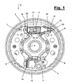
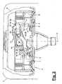
- FIG. 1 and 2 clarify this configuration.
- the wheel brake (2) can be provided with a return mechanism (11) which reduces or eliminates the braking effect when the vehicle wheel (1) is reversing, whereby at least one brake shoe (6, 7) is disengaged from the brake drum (5).
- the return mechanism (11) can be designed and arranged in various ways. In the embodiment shown, it is corresponding to EP 0 261 660 A1 formed and consists of a support member and at least one evading cam when reversing. This allows for reverse drive a mutual approach of the brake shoe ends and a cancellation of the braking effect.
- the automatic return as in the EP 0 482 430 B1 be formed and allow it to dodge a pad carrier of the brake shoe against its web when reversing.
- an adjustment mechanism (12) is arranged on the support (10) having a Nachstelltechnikrad with a threaded ram, the Nachstelltechnikrad through an opening in the brake shield (4) is accessible from the outside and mounted wheel brake (2) a Adjustment possible.
- the span of the support (10) can be changed. This allows adjustment and adjustment of the brake shoes (6,7) and their brake air in the release position.
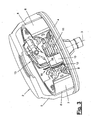
- FIG. 3 shows this brake air (8) between brake shoes (6,7) and brake drum (5).
- the spreading device (13) is provided with an adjusting device (19), with which the wear of the brake pads can be automatically compensated. With increasing wear of the application of the brake shoes (6,7) on the brake drum (5) required Zuspannweg or Sp Schwarzweg is greater. With the adjusting device (19) this travel magnification is compensated.
- the adjusting device (19) is also provided with a release device (28) which, in the event of an enlarged and abnormal brake actuation stroke, overrides the adjustment device (19).
- the release device (28) is e.g. activated by the occurrence of the increased Bremsbetuschistshubs and possibly in dependence on the size of Hubzutes.
- Such an increased stroke on the brake actuator (3) arises e.g. in the aforementioned reverse drive under the action of a reverse automatic (11).
- the one or more evasive brake shoes (6,7) allow an enlargement of the Sp Schwarzwegs on the spreader (13). Without release device (28), this increase in travel would be misinterpreted as wear on the adjusting device (19) and lead to an irreversible Sp Dr Drishnach ein.
- other causes of stroke augmentation are possible, e.g. thermally induced temporary and reversible strains or the like
- the adjusting device (19) has an actuating part (20) and a readjusting member (23), which are moved relative to each other during the braking operation under the action of the actuating member (3).
- the release device (28) is released when an increased Bremsbetuschistshubs and eg when exceeding a predetermined stroke size or switching threshold of the adjustment of adjusting part (20) and adjusting member (23), so that no Adjustment takes place.
- the brake shoes (6,7) can return to their starting position for normal braking and Nachstell too after completion of the reverse drive and renewed forward movement.
- the spreading device (13) may be formed in any suitable manner and is e.g. designed as a turnbuckle, which is actuated by a brake cable or a Bowden cable (3).
- the spreading device (13) has a spreading element (14), which is designed as a tensioning lever in the case of a turnbuckle, which is rotatably mounted by means of a pivot axis (32) on a fork-shaped housing (15) and connected to the actuating member (3).
- the clamping lever (14) has at one end of the lever (16) a recess (17) as a jaw receiving, in which form-locking the web (9) of a brake shoe (6) engages.
- the adjusting part (20) can be designed in any suitable manner.
- it consists of a spur gear (21), which is rotatably mounted about an axis lying in the spreading direction on the housing (15) and connected to a threaded ram (22).
- the threaded ram (22) carries at its front free end of the aforementioned fork piece (18) and is mounted via a counter-thread in the gear (21) or at another suitable location.
- a rotation of the gear (21) thereby causes a longitudinal adjustment of the threaded ram (22) and the jaw holder (18).
- the adjusting member (23) of the adjusting device (19) is designed, for example, as a one-piece or multi-part adjusting lever, which is mounted rotatably about a pivot axis (24) on the housing (15).
- a pivot axis (24) on the housing (15).
- the adjusting lever (23) has in the embodiment of Figure 1 to 11 a one-piece and angled lever arm (39). He is connected at its rear end in a suitable manner with the brake actuator. This can be done for example via an angled driver (25) which engages positively in a recess (38) at the rear end of the lever (16) of the clamping lever (14). A rotation of the clamping lever (14) then causes the same direction rotation of the adjusting lever (23). Alternatively, the brake actuator can be converted in any other way into a corresponding rotation of the adjusting lever (23).
- the lever arm (39) can have an angled shape in the region between the pivot axis (24) and the positioning nose (26).
- the lever arm (39) consists of a flat sheet metal part whose main plane is aligned substantially parallel to the adjacent surface of the housing (15) and extending transversely to the pivot axis (24).
- FIG. 8 and 9 illustrate the engagement of the adjusting member (23) and the actuating part (20) in normal braking operation.
- the toothed nose (26) which is twice angled toward the toothed wheel (21), engages in the intermediate space (37) between two teeth (36) of the toothed wheel (21) in the case of a relaxed spreader (23).
- the lever design and the gear geometry are coordinated so that the front edge (27) moves in this clearance or backlash (37) back and forth in normal braking operation and with the Sp Sondorf occurring thereby and no rotation of the gear (21) triggers.
- the teeth (36) may have a tilt in the direction of adjustment, which supports this actuation-free lever play.
- the release device (28) has a control member (29), in particular a lifting member which, when occurring and depending on an increased Bremsbetuschistshub and a correspondingly large relative movement of actuator (20) and adjusting member (23) these parts (20,23) from each other and disengages.
- the control member (29) is arranged to a position in the range of movement of the Nachstellorgans (23), which is outside the normal path for wear compensation and defines the switching threshold for the occurrence of an increased BremsbetHence Trents.
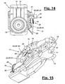
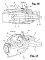
- the embodiments of Figure 1 to 11 and FIGS. 12 to 17 show two variants of the control member (29).
- the lifting member (29) as a cam (29 ') and formed in FIG. 8 shown. It acts on the adjusting member (23) and raises this far enough that the engagement with the control part (20) is released.
- the cam (29 ') has for this purpose an obliquely rising cam flank (30) and a subsequent angled cam surface (31), which can serve as a support surface for the adjusting member (23).
- the transition between the surfaces (30,31) may be sharp-edged, wherein the Nachstellorgan (23), in particular the adjusting lever, may have a corresponding angled shape in the contact area to form a defined detent position.
- the angled cam surface (31) may be aligned substantially perpendicular to the pivot axis (24), so that the alsg facedde adjusting lever (23) in this area substantially free of deformation rests and by frictional force is held.
- the cam surface (31) can be angled downwards, which can lead to a corresponding elastic deformation of the adjusting lever (23) and to a corresponding positive locking of the assumed lever position.
- the lifting member (29) may be fixedly mounted on the housing (15).
- the lifting member (29) and the cam (29 ') on a pivot lever (33) is arranged, which is arranged between the adjusting lever (23) and the adjacent wall of the housing (15).
- the pivot lever (33) is in turn rotatably mounted on the spreader (13) and the housing (15). Preferably, it has the same pivot axis (24) as the adjusting lever (23).
- the pivoting of the pivot lever (33) is limited.
- stationary stops (34,35) on the housing (15) may be arranged.
- the pivoting lever (33) formed from a flat sheet metal part may have an angled shape and at the front end have a bent-over edge region together with the bent-up cam (29 ').
- the pivoting of the pivot lever (33) is matched to the tooth width of the gear (21).
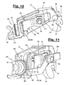
- FIGS. 10 and 11 illustrate this situation described above.
- the lowered adjusting lever (23) with its lever arm (39) presses the pivot lever back into the starting position at the lower stop (35).
- FIGS. 12 to 17 show a modification of the adjusting device (19) and the release device (28).
- the other parts of the spreader (13) and the wheel brake (2) may be the same as in the above-described embodiment.
- Like numbers refer to corresponding items.
- the adjusting member (23) is in turn designed as an adjusting lever, whose flat lever arm (39) is formed in two parts in this case.
- the two arm parts (40, 41) are connected to one another by a joint (42) lying transversely to the arm direction.
- the hinge (42) is located between the pivot axis (24) and the adjusting lug (26).
- the front arm part (40) of the positioning nose (26) can be swiveled up and down via the joint (42) and thereby execute a lifting and lowering movement similar to the elastically deformable lever arm (39) in the first embodiment.
- the hinged lever arm (39) has a spring (43) which bridges the joint (42) and which is fastened to an arm part (40, 41) at each end.
- the spring (43) acts in the release direction of the Nachstelleingriffs and tries the Stellnase (26) from the actuating element (20) lift.
- the spring (43) formed as a tension spring and arranged on the upper side of the lever arm (39).
- the release device (28) has a control element (29) in the form of a slotted guide (29 ") .
- the slide guide (29") is arranged, for example, stationarily on the outer wall of the housing (15) facing the adjusting lever (23) and is located in a position in the range of movement of the adjusting lever (23), which defines the switching threshold for the occurrence of an increased Bremsbetutz Trents.
- the slotted guide (29 ") is in FIG. 17 without adjusting lever (23).
- the slide guide (29 ") guides the front arm part (40) with the adjusting lug (26) as a function of the lever position or the rotational position of the adjusting lever (23) and controls its releasing and engaging movement
- the sliding guide (29") has at least a guide strip (44) which is provided with at least one stroke path (45) and with a lowering path (46).
- the spring (43) keeps the front arm part (40) in guiding contact with the lowering track (46).
- the guide strip (44) may be formed as a one-piece or multi-part guide bracket.
- the strip part with the oblique stroke path (45) similar to the cam (29 ') is arranged and formed.
- the stroke path (45) is located in a pivoting range of the adjusting lever (23), in which this occurs when an increased Bremsbestrucrienshubs occurs and provides with its inclined surface or Aufgleitflanke for lifting or swiveling up of the front arm part (40) to release the Nachstelleingriffs.
- the pivotal movement is assisted by the spring (43) and can be limited as appropriate.
- an anvil may be present on the guide strip (44).
- the above the arm (40) arranged lowering path (46) comes into operation and presses by their obliquely sloping orientation the angled arm part (40) against the force of the spring (43) down back into the engaged position on the adjusting element (20).
- the lowering path (46) is arranged for this purpose in the pivoting and moving range of the adjusting member (23) in the normal braking and adjusting function.
- the Senkbahn (46) can have the same function as the pivot lever (33) on their training and arrangement by delays the arm part (40) and the adjusting lug (26) delayed.
- the obliquely downward guide surface of the Senkbahn (46) for this purpose has a set back in the pivoting angle position and only acts lowering on the arm part (40) when the adjusting lever (23) has covered an initial pivoting when pivoting back, being held in this release position on the actuating element (20) on this pivoting.
- the lowering track (46) may also have an initial area aligned parallel to the lever pivoting movement forming the aforesaid counter bearing.
- the guide strip (44) can also form an end stop for limiting the remindschwenkbegung of the adjusting lever (23) and for this purpose have a groove-shaped lateral recess.
- the upper oblique Nutenrand forms the Senkbahn (46).
- the lower housing-parallel edge optionally forms a bearing surface for the arm part (40).
- the lowering path (46) can also be effective in the normal pivoting and readjusting movements of the adjusting device (19) and lend the adjusting nose (26) a small lifting and lowering movement within the framework of the backlash.
- the adjusting member (23) and the adjusting member (20) may be formed in any other way and arranged elsewhere and have a different kinematics.
- the readjustment movement can take place, for example, via a linear ratchet movement, wherein the brake actuation forces and movements are correspondingly deflected and the release device (28) is configured differently.
- the adjusting device (19) may be formed, for example, in the manner of actuation of a caulking gun, in which a pivot lever acts by means of an inclined position and clamping closure on a rod inserted through a lever opening.
- the support of the rod-shaped element can be loosened, so that the Stem aligns with the lever in a way that the leverage is not transferred and no bar feed occurs. Further, it is possible to dispense with a separate adjusting member (23) and in particular an adjusting lever and instead to use the clamping lever (14) as adjusting member.
- the release device (28) may have a different design and kinematics. Also, the engagement of the adjusting member (23) and the adjusting member (20) can be solved in another way, e.g. by an axial displacement of the actuating part (20) relative to the adjusting member (23). Instead of the lifting member (29) can be used in this case a thrust member. In a further modification it is possible to eliminate the function and kinematics of the release device (28) from the brake actuation and e.g. from the movements of the clamping lever (14), derive. For this purpose, e.g. on the cocking lever (14) a casserole or the like.
- a pin or other actuating part is actuated and thereby acting on the adjusting member (23) for releasing the engagement with the actuating part (20).
- This control pin can e.g. the adjusting lever (23) in a similar manner as the control or lifting member (29). Lift.
- the design of the other parts of the wheel brake (2) in particular the spreading device (13), the brake shoes (6,7) and the support (10).
- the invention can also be carried out with other types of training, linkages and kinematics of brake shoes, which attack instead of a brake drum (5) on another brake member.
Landscapes
- Engineering & Computer Science (AREA)
- General Engineering & Computer Science (AREA)
- Mechanical Engineering (AREA)
- Braking Arrangements (AREA)
- Valve Device For Special Equipments (AREA)
Description
- Die Erfindung betrifft eine Radbremse mit den Merkmalen im Oberbegriff des Hauptanspruchs.
- Eine solche Radbremse in Form einer Innenbackenbremse mit Nachstelleinrichtung ist aus der
EP 0 482 430 B1 bekannt. Sie besteht aus einer Bremstrommel mit darin gelagerten Innenbremsbacken, die an ihren Enden mittels einer Abstützung und einer Spreizeinrichtung miteinander verbunden sind. Im Bereich der Spreizeinrichtung ist eine Nachstelleinrichtung angeordnet, welche ein Einstellteil in Form eines Nachstellzahnrads mit Gewindestößel und ein Nachstellorgan in Form eines Nachstellhebels aufweist. Der Nachstellhebel und das Nachstellzahnrad sind bei Betätigung der Radbremse relativ zueinander bewegbar, wobei der Nachstellhebel bei Auftreten von Bremsverschleiß das Nachstellzahnrad ratschenartig weiterschaltet und über den entsprechend ausgefahrenen Gewindestößel die Spreizbreite der Spreizeinrichtung vergrößert. Die vorbekannte Radbremse ist mit einer Rückfahrautomatik ausgestattet, die bei Rückwärtsfahrt das Ausweichen von mindestens einer Bremsbacke ermöglicht und die Bremswirkung mindert oder aufhebt. In einem solchen Fall tritt ein vergrößerter Bremsbetätigungshub auf, der zu einem unerwünschten Verstellen der Nachtelleinrichtung führen könnte. Um dies zu vermeiden, ist bei derEP 0 482 430 B1 die Nachstelleinrichtung mittels eines stabförmigen Verbindungsglieds mit der ausweichfähig gelagerten Bremsbacke verbunden, wobei diese Verbindung bei der Rückwärtsfahrt und bei einem Ausweichen der Bremsbacke gelöst werden kann. Diese Konstruktion wirft einerseits Toleranz- und Einstellprobleme auf und bedingt andererseits eine bestimmte Ausbildung der Rückfahrautomatik und der Bremsbacken. - Es ist Aufgabe der vorliegenden Erfindung, eine verbesserte Radbremse mit einer Nachstelleinrichtung aufzuzeigen.
- Die Erfindung löst diese Aufgabe mit den Merkmalen im Hauptanspruch.
Die beanspruchte Ausgestaltung der Nachstelleinrichtung hat den Vorteil, dass sie sich für beliebige Radbremsen und für beliebige Ausführungen einer Rückfahrautomatik eignet. Die mit der Nachstelleinrichtung versehene Spreizeinrichtung kann auch bei Radbremsen ohne Rückfahrautomatik vorgesehen sein und ermöglicht deren späteres Nachrüsten. Ferner lassen sich auch vorhandene Radbremsen mit der Nachstelleinrichtung nachrüsten. - Von besonderem Vorteil sind die hohe Betriebssicherheit der Nachstelleinrichtung sowie der geringe Bau- und Platzaufwand. Die Spreizeinrichtung mit der Nachstelleinrichtung hat im wesentlichen die gleiche Baugröße und die gleichen Anschlüsse wie eine konventionelle Spreizeinrichtung. Dies erlaubt eine Standardisierung der Radbremse. Eine spezielle Adaption der anderen Radbremsteile, insbesondere der Bremsbacken, ist nicht erforderlich. Günstig wirken sich ferner die mechanische Robustheit der beanspruchten Nachstelleinrichtung sowie ihre einfache Bedienbarkeit aus.
- Die Löseeinrichtung ist integraler Bestandteil der Nachstelleinrichtung und wirkt intern, indem bei Bedarf der Eingriff der Einrichtungsteile gelöst wird. Diese Technik ist weniger toleranz- und fehleranfällig als beim Stand der Technik und bietet eine höhere Betriebs- und Funktionssicherheit.
- Die Löseeinrichtung kann bei Auftreten eines vergrößerten Bremshubs aktiv werden, der nur temporär auftritt und reversibel ist, wobei die Ursache für die Bremshubvergrößerung gleichgültig ist. Hierdurch kann sowohl auf eine Bremshubvergrößerung bei Rückwärtsfahrt und ausweichenden Bremselementen, als auch bei verschleißmäßig oder thermisch bedingten oder aus anderen Gründen vorhandenen anormalen Hubvergrößerungen reagiert werden. Die Aktivierung kann vom Bremshub direkt abhängig sein und insbesondere bei Überschreiten einer vorgebenen Hubgröße oder Schaltschwelle erfolgen. Die Hubgröße ist vorzugsweise der Auslöser. Die Löseeinrichtung kann dadurch ursachenneutral reagieren und zuverlässig verhindern, dass in solchen Fällen eine unerwünschte Bremsnachstellung erfolgt. Die Nachstelleinrichtung kann zwischen Normalbetrieb der Bremse und ungewöhnlichen Betriebsbedingungen unterscheiden, so dass ein Nachstellen der Bremse zur Kompensation des normalen Bremsverschleisses geschieht
- Vorteilhaft ist außerdem, dass die Radbremse an der Abstützung einen zusätzlichen Einstellmechanismus haben kann, um die Grundeinstellungen der Radbremse vorzunehmen. Die Nachstelleinrichtung an der Spreizeinrichtung braucht dann nur noch für die Verschleißaufnahme im Betrieb zu sorgen.
- In den Unteransprüchen sind weitere vorteilhafte Ausgestaltungen der Erfindung angegeben.
- Die Erfindung ist in den Zeichnungen beispielsweise und schematisch dargestellt. Im einzelnen zeigen:
- Figur 1:
- eine Stirnansicht einer geöffneten Radbremse bei abgenommener Bremstrommel,
- Figur 2:
- eine Draufsicht auf die Radbremse von
Figur 1 gemäß Pfeil II nebst angedeuteter Bremstrommel und Fahrzeugrad, - Figur 3:
- eine perspektivische Ansicht einer aufgeschnittenen Radbremse in ungebremster Stellung,
- Figur 4:
- eine perspektivische Ansicht einer aufgeschnittenen Radbremse in Bremsstellung,
- Figur 5 und 6:
- unterschiedliche perspektivische Ansichten einer geöffneten Radbremse,
- Figur 7:
- eine vergrößerte Stirnansicht einer Spreizeinrichtung mit einer Nachstelleinrichtung,
- Figur 8:
- eine vergrößerte und gedrehte Seitenansicht der Nachstelleinrichtung gemäß Pfeil XIII von
Figur 7 , - Figur 9 bis 11:
- verschiedene perspektivische Ansichten der Spreizeinrichtung mit der Nachstelleinrichtung in verschiedenen Betriebsstellungen,
- Figur 12 bis 17:
- eine Variante der Nachstelleinrichtung in verschiedenen Ansichten und
- Figur 18 und 19:
- einen Fahrzeuganhänger mit Radbremsen und einer Auflaufbremseinrichtung in Seitenansicht und Draufsicht.
- Die Erfindung betrifft eine Radbremse (2) für Fahrzeugräder (1) und ein damit ausgerüstetes Fahrzeug (50). Hierbei handelt es sich z.B. um den in
Figur 18 und 19 gezeigten Fahrzeuganhänger mit einem Fahrgestell (51), mit ein oder mehreren Achsen (52) und mit einer starren oder beweglichen Zugdeichsel (53), an der eine Anhängerkupplung (54) und eine Auflaufbremseinrichtung (55) sowie eine ggf. mit einem Federspeicher ausgestattete Handbremseinrichtung (56) angeordnet sind. Von den Bremseinrichtungen (55,56) werden die Bremskräfte mittels eines Bremsbetätigungsorgans (3), z.B. eines Bremsgestänges und/oder eines Seilzugs auf die Radbremsen (2) übertragen. - Die Radbremse (2) ist im gezeigten Ausführungsbeispiel als Trommelbremse ausgebildet und besteht aus ein oder mehreren Bremsbacken (6,7), die innerhalb der Bremstrommel (5) angeordnet sind und mittels einer Spreizeinrichtung (13) unter Einwirkung des Betätigungsorgans (3) gegen die Rückstellkraft von nicht dargestellten Bremsenfedern gespannt oder gelöst werden. Die Bremsbacken (6,7) bestehen z.B. aus einem konzentrisch zur Radnabe gebogenen Belagträger und einem damit fest verbundenen, quer abstehenden Steg (9). Die Bremsbacken (6,7) sind in der Radbremse (2) zwischen einem rückseitigen Bremsschild (4) und der Bremstrommel (5) angeordnet und werden durch Federn am Bremsschild (4) in führender Anlage gehalten. An der Bremstrommel (5) wird das Fahrzeugrad (1) in geeigneter Weise befestigt.
- Zwischen den Bremsbacken (6,7) und deren Stegen (9) ist am einen Ende die schwimmend gelagerte Spreizeinrichtung (13) angeordnet. Am anderen Ende ist eine mit dem Bremsschild (4) verbundene Abstützung (10) vorhanden, welche die Backenenden miteinander verbindet und im normalen Bremsbetrieb ortsfest abstützt.
Figur 1 und2 verdeutlichen diese Ausgestaltung. - Die Radbremse (2) kann mit einer Rückfahrautomatik (11) versehen sein, welche bei Rückwärtsfahrt des Fahrzeugrads (1) die Bremswirkung mindert oder aufhebt, wobei zumindest eine Bremsbacke (6,7) außer Eingriff mit der Bremstrommel (5) gebracht wird. Die Rückfahrautomatik (11) kann in verschiedener Weise ausgebildet und angeordnet sein. In der gezeigten Ausführungsform ist sie entsprechend der
EP 0 261 660 A1 ausgebildet und besteht aus einem Stützglied und mindestens einem bei Rückwärtsfahrt ausweichenden Nocken. Dies ermöglicht bei Rückwärtsfahrt eine gegenseitige Annäherung der Bremsbackenenden und eine Aufhebung der Bremswirkung. Alternativ kann die Rückfahrautomatik wie in derEP 0 482 430 B1 ausgebildet sein und bei Rückwärtsfahrt ein Ausweichen eines Belagträgers der Bremsbacke gegenüber seinem Steg erlauben. - In der gezeigten Ausführungsform ist an der Abstützung (10) ein Einstellmechanismus (12) angeordnet, der ein Nachstellzahnrad mit einem Gewindestößel aufweist, wobei das Nachstellzahnrad durch eine Öffnung im Bremsschild (4) von außen her zugänglich ist und bei montierter Radbremse (2) eine Nachstellung ermöglicht. Über den Einstellmechanismus (12) kann die Stützweite der Abstützung (10) verändert werden. Dies ermöglicht eine Einstellung und Justierung der Bremsbacken (6,7) und ihrer Bremsluft in Lösestellung.
Figur 3 zeigt diese Bremsluft (8) zwischen Bremsbacken (6,7) und Bremstrommel (5). - Die Spreizeinrichtung (13) ist mit einer Nachstelleinrichtung (19) versehen, mit welcher der Verschleiß der Bremsbeläge automatisch kompensiert werden kann. Mit zunehmenden Verschleiß wird der zum Anlegen der Bremsbacken (6,7) an der Bremstrommel (5) erforderliche Zuspannweg oder Spreizweg größer. Mit der Nachstelleinrichtung (19) wird diese Wegvergrößerung kompensiert.
- Die Nachstelleinrichtung (19) ist außerdem mit einer Löseeinrichtung (28) versehen, welche bei einem vergrößerten und anormalen Bremsbetätigungshub die Nachstelleinrichtung (19) außer Kraft setzt. Die Löseeinrichtung (28) wird z.B. durch das Auftreten des vergrößerten Bremsbetätigungshubs und ggf. in Abhängigkeit von der Größe der Hubzunahme aktiviert. Ein solcher vergrößerter Hub am Bremsbetätigungsorgan (3) entsteht z.B. bei der vorerwähnten Rückwärtsfahrt unter der Einwirkung einer Rückfahrautomatik (11). Die ein oder mehreren ausweichenden Bremsbacken (6,7) ermöglichen eine Vergrößerung des Spreizwegs an der Spreizeinrichtung (13). Ohne Löseeinrichtung (28) würde diese Wegvergrößerung als Verschleiß von der Nachstelleinrichtung (19) fehlinterpretiert werden und zu einer irreversiblen Spreizwegnachstellung führen. Daneben sind auch andere Ursachen für eine Hubvergrößerung möglich, z.B. thermisch bedingte temporäre und reversible Dehnungen oder dgl..
- Die Nachstelleinrichtung (19) besitzt ein Stellteil (20) und ein Nachstellorgan (23), die bei der Bremsbetätigung unter Einwirkung des Betätigungsorgans (3) relativ zueinander bewegt werden. Mit der Löseeinrichtung (28) wird bei Auftreten eines vergrößerten Bremsbetätigungshubs und z.B. bei Überschreiten einer vorgegebenen Hubgröße oder Schaltschwelle der Nachstelleingriff von Stellteil (20) und Nachstellorgan (23) gelöst, so dass keine Nachstellung erfolgt. Die Bremsbacken (6,7) können nach Beendigung der Rückwärtsfahrt und erneuter Vorwärtsfahrbewegung wieder in ihre Ausgangsposition für einen normalen Brems- und Nachstellbetrieb zurückkehren.
- Die Spreizeinrichtung (13) kann in beliebig geeigneter Weise ausgebildet sein und ist z.B. als ein Spannschloss gestaltet, welches von einem Bremsseil bzw. einem Bowdenzug (3) betätigt wird. Die Spreizeinrichtung (13) besitzt ein Spreizelement (14), welches im Falle eines Spannschlosses als Spannhebel ausgebildet ist, der mittels einer Schwenkachse (32) an einem gabelförmigen Gehäuse (15) drehbar gelagert und mit dem Betätigungsorgan (3) verbunden ist. Der Spannhebel (14) hat am einen Hebelende (16) eine Ausnehmung (17) als Backenaufnahme, in welche formschlüssig der Steg (9) der einen Bremsbacke (6) greift.
- Am Gehäuse (15) ist an dem der anderen Bremsbacke (7) zugekehrten Ende das Stellteil (20) angeordnet, welches mittels einer Backenaufnahme (18), z.B. einem Gabelstück, in Eingriff mit dem Steg (9) der anderen Bremsbacke (7) steht. Die Hebelübersetzung des Spannhebels (14) ist so gewählt, dass beim Anziehen des Betätigungsorgans (3) der Abstand zwischen den Backenaufnahmen (17,18) und der hierdurch gebildete Spreizweg vergrößert wird.
- Das Stellteil (20) kann in beliebig geeigneter Weise ausgebildet sein. Im gezeigten Ausführungsbeispiel besteht es aus einem Stirnzahnrad (21), welches um eine in Spreizrichtung liegende Achse drehbar am Gehäuse (15) gelagert und mit einem Gewindestößel (22) verbunden ist. Der Gewindestößel (22) trägt an seinem vorderen freien Ende das erwähnte Gabelstück (18) und ist über ein Gegengewinde im Zahnrad (21) oder an anderer geeigneter Stelle gelagert. Eine Drehung des Zahnrades (21) bewirkt dadurch eine Längsverstellung des Gewindestößels (22) und der Backenaufnahme (18).
- Das Nachstellorgan (23) der Nachstelleinrichtung (19) ist z.B. als einteiliger oder mehrteiliger Nachstellhebel ausgebildet, der um eine Schwenkachse (24) drehbar am Gehäuse (15) gelagert ist. In den Zeichnungen von
Figur 1 bis 11 undFigur 12 bis 17 sind zwei Varianten des Nachstellorgans (23) dargestellt. - Der Nachstellhebel (23) besitzt in der Ausführungsform von
Figur 1 bis 11 einen einteiligen und abgewinkelten Hebelarm (39). Er ist an seinem rückwärtigen Ende in geeigneter Weise mit der Bremsbetätigung verbunden. Dies kann z.B. über einen abgewinkelten Mitnehmer (25) erfolgen, der in eine Ausnehmung (38) am hinteren Hebelende (16) des Spannhebels (14) formschlüssig eingreift. Eine Drehung des Spannhebels (14) bewirkt dann eine gleichsinnige Drehung des Nachstellhebels (23). Alternativ kann die Bremsbetätigung auf beliebige andere Weise in eine entsprechende Drehung des Nachstellhebels (23) umgesetzt werden. - Am vorderen Armende hat der Nachstellhebel (23) eine mehrfach abgewinkelte Stellnase (26), welche mit einer Vorderkante (27) in Eingriff mit dem Stellteil (20) und insbesondere dem Zahnrad (21) tritt. Der Hebelarm (39) kann im Bereich zwischen der Schwenkachse (24) und der Stellnase (26) eine abgewinkelte Form haben. Der Hebelarm (39) besteht aus einem flachen Blechteil, dessen Hauptebene im wesentlichen parallel zur benachbarten Oberfläche des Gehäuses (15) ausgerichtet ist und sich quer zur Schwenkachse (24) erstreckt. Durch diese Gestaltung hat der Nachstellhebel (23) eine Biegeelastizität, welche für die nachfolgend erläuterte Löseeinrichtung (28) bedeutsam ist und ein Lösen des Eingriffs mit dem Zahnrad (21) durch elastische Verformung des Hebelarms (39) ermöglicht.
-
Figur 8 und9 verdeutlichen den Eingriff des Nachstellorgans (23) und des Stellteils (20) im normalen Bremsbetrieb. Die zum Zahnrad (21) hin zweifach abgewinkelte Stellnase (26) greift bei entspannter Spreizeinrichtung (23) in den Zwischenraum (37) zwischen zwei Zähnen (36) des Zahnrads (21). Die Hebelauslegung und die Zahnradgeometrie sind derart aufeinander abgestimmt, dass im normalen Bremsbetrieb und mit den dabei auftretenden Spreizwegen die Vorderkante (27) sich in diesem Freiraum oder Zahnspiel (37) hin und her bewegt und keine Drehung des Zahnrads (21) auslöst. Die Zähne (36) können eine Neigung in Stellrichtung haben, welche dieses betätigungsfreie Hebelspiel unterstützt. Wenn Verschleiß auftritt und der Spreizweg entsprechend größer wird, vergrößert sich auch der Schwenkweg des Nachstellhebels (23), wobei die Vorderkante (27) über den benachbarten Zahn (36) gleitet und in die nächstfolgende Ausnehmung (37) taucht. Die Stellnase (26) wird hierbei z.B. in der inFigur 9 durch einen Richtungspfeil gekennzeichneten Weise gegen den Uhrzeigersinn gedreht. Beim Entspannen der Radbremse (2) und einem Zurückdrehen des Nachstellhebels (23) hintergreift die Nachstellnase (26) den überfahrenen Zahn (36) und dreht bei der Rückwärtsbewegung das Zahnrad (21) um eine Zahnteilung weiter. - Wenn in der eingangs erwähnen Weise ein vergrößerter Bremsbetätigungshub auftritt, der über das normale Bremsluftspiel und über die Aufnahme eines normalen Verschleißes hinausgeht, würde ohne die Löseeinrichtung (28) die Stellnase (26) beim Entspannen der Bremse das Zahnrad (21) drehen und die Radbremse nachstellen, obwohl kein aufzunehmender Verschleiß vorliegt. Dies würde zu einer dauerhaften Vergrößerung des Spreizwegs und zu einem Anliegen der Bremsbacken (6,7) im normalen Fahrbetrieb an der Bremstrommel (5) führen. Unter Umständen würde die Radbremse (2) blockieren. Ferner wäre es möglich, dass die Rückfahrautomatik (11) nicht wieder in ihre Ausgangsposition zurückkehrt und die Abstützung (10) ihre normale Wirkung nicht mehr einnehmen kann. Dies wird durch die Löseeinrichtung (28) in der vorerwähnten Weise verhindert.
- Die Löseeinrichtung (28) besitzt ein Steuerorgan (29), insbesondere ein Huborgan, welches bei Auftreten und in Abhängigkeit von einem vergrößerten Bremsbetätigungshub und einer entsprechend großen Relativbewegung von Stellteil (20) und Nachstellorgan (23) diese Teile (20,23) voneinander distanziert und außer Eingriff bringt. Das Steuerorgan (29) ist dazu an einer Position im Bewegungsbereichs des Nachstellorgans (23) angeordnet, die außerhalb des normalen Stellwegs zur Verschleißkompensation liegt und die Schaltschwelle für das Auftreten eines vergrößerten Bremsbetätigungshubs definiert. Die Ausführungsbeispiele von
Figur 1 bis 11 undFigur 12 bis 17 zeigen zwei Varianten des Steuerorgans (29) . - Im Ausführungsbeispiel von
Figur 1 bis 11 ist das Huborgan (29) als Nocke (29') ausgebildet und inFigur 8 dargestellt. Sie wirkt auf das Nachstellorgan (23) ein und hebt dieses soweit an, dass der Eingriff zum Stellteil (20) gelöst wird. Die Nocke (29') hat hierfür eine schräg ansteigende Nockenflanke (30) und eine anschließende abgewinkelte Nockenfläche (31), die als Auflagefläche für das Nachstellorgan (23) dienen kann. Der Übergang zwischen den Flächen (30,31) kann scharfkantig sein, wobei das Nachstellorgan (23), insbesondere der Nachstellhebel, eine entsprechende abgewinkelte Formgebung im Kontaktbereich haben kann, um eine definierte Rastposition zu bilden. Die abgewinkelte Nockenfläche (31) kann im wesentlichen senkrecht zur Schwenkachse (24) ausgerichtet sein, so dass der aufgleitende Nachstellhebel (23) in diesem Bereich im wesentlichen verformungsfrei aufliegt und durch Reibkraft gehalten wird. Alternativ kann die Nockenfläche (31) schräg abwärts abgewinkelt sein, was zu einer entsprechenden elastischen Verformung des Nachstellhebels (23) und zu einer entsprechenden formschlüssigen Sicherung der eingenommenen Hebelposition führen kann. - Das Huborgan (29) kann ortsfest am Gehäuse (15) angeordnet sein. In der gezeigten und bevorzugten Ausführungsform ist das Huborgan (29) bzw, die Nocke (29') auf einem Schwenkhebel (33) angeordnet, der zwischen dem Nachstellhebel (23) und der benachbarten Wandung des Gehäuses (15) angeordnet ist. Der Schwenkhebel (33) ist seinerseits drehbar an der Spreizeinrichtung (13) und am Gehäuse (15) gelagert. Vorzugsweise hat er die gleiche Schwenkachse (24) wie der Nachstellhebel (23).
- Der Schwenkweg des Schwenkhebels (33) ist begrenzt. Hierfür können stationäre Anschläge (34,35) am Gehäuse (15) angeordnet sein. Der aus einem flachen Blechteil gebildete Schwenkhebel (33) kann eine abgewinkelte Form aufweisen und am vorderen Ende einen aufgebogenen Randbereich nebst der hochgebogenen Nocke (29') aufweisen. Der Schwenkweg des Schwenkhebels (33) ist auf die Zahnweite des Zahnrads (21) abgestimmt.
- Im normalen Bremsbetrieb können der Schwenkhebel (33) und das Huborgan (29) außer Funktion sein und eine Ruhestellung am unteren Anschlag (35) einnehmen. Der entsprechend der Bremsbetätigung hin und her geschwenkte Nachstellhebel (23) bewegt sich innerhalb des Zahnspiels und dreht bei Verschleiß das Zahnrad (21) ggf. um einen Zahn weiter. Ggf. kann der Nachstellhebel (23) bei dieser Verschleißkompensation auf der schrägen Nockenflanke (30) ein kleines Stück aufgleiten und dadurch leichter über den Zahn (36) gleiten. Der Nachstellhebel (23) hält den Schwenkhebel (33) in der Anschlagposition am unteren Anschlag (35).
- Erst bei Auftreten des vergrößerten Bremsbetätigungshubs gleitet der Nachstellhebel (23) auf der entsprechend positionierten schrägen Nockenflanke (30) bis zu deren oberem Ende auf und liegt anschließend mit federnder Spannkraft auf der Nockenfläche (31). Durch dieses Anheben des Hebelarms kommt die Vorderkante (27) außer Eingriff mit dem Zahnrad (21).
- Beim Lösen des Bremsbetätigungsorgans (3) wird der Nachstellhebel (23) über die inneren Federkräfte der Radbremse (2) und den Spannhebel (14) wieder zurückbewegt, wobei er über den Reibschluss und ggf. Formschluss den Schwenkhebel (33) mitnimmt, bis dieser am oberen Anschlag (34) zur Anlage kommt und stehen bleibt. Erst aus dieser Anschlagstellung heraus bewegt sich der Nachstellhebel (23) über seinen weiteren Schwenkweg relativ zur Nocke (29') und gleitet an dieser wieder entlang nach unten, bis die Vorderkante (27) wieder in Eingriff mit dem Zahnrad (21) tritt. Durch diese Gestaltung wird erreicht, dass die Vorderkante (27) der Stellnase (26) wieder genau in die Ausgangsstellung am Zahnrad (21) und in den Zahnzwischenraum (37) zurückkehrt ohne das Zahnrad (21) in unerwünschter Weise zu drehen. Durch den Schwenkhebel (33) bleibt der Nachstellhebel (23) im Anfangsbereich der Rückschwenkbewegung genügend lange in angehobener Stellung eingriffsfrei über dem Zahnrad (21) und taucht erst an der gewünschten Position wieder in den Zahneingriff ab.
Figur 10 und 11 verdeutlichen diese vorbeschriebene Situation. InFigur 10 ist der Schwenkhebel ohne den Nachstellhebel (23) zu sehen. Im normalen Brems- und Nachstellbetrieb drückt der abgesenkte Nachstellhebel (23) mit seinem Hebelarm (39) den Schwenkhebel wieder zurück in die Ausgangsposition am unteren Anschlag (35).Figur 12 bis 17 zeigen eine Abwandlung der Nachstelleinrichtung (19) und der Löseeinrichtung (28). Die anderen Teile der Spreizeinrichtung (13) und der Radbremse (2) können die gleichen wie im vorbeschriebenen Ausführungsbeispiel sein. Gleiche Bezugsziffern betreffen korrespondierende Gegenstände. - Das Nachstellorgan (23) ist wiederum als Nachstellhebel ausgebildet, dessen flacher Hebelarm (39) in diesem Fall zweiteilig ausgebildet ist. Die beiden Armteile (40,41) sind durch ein quer zur Armrichtung liegendes Gelenk (42) miteinander verbunden. Das Gelenk (42) befindet sich zwischen der Schwenkachse (24) und der Stellnase (26). Der vordere Armteil (40) der Stellnase (26) kann über das Gelenk (42) auf und ab geschwenkt werden und dabei eine Hub- und Senkbewegung ähnlich wie der elastisch verformbare Hebelarm (39) im ersten Ausführungsbeispiel ausführen.
- Der klappbare Hebelarm (39) weist eine Feder (43) auf, die das Gelenk (42) überbrückt und die endseitig an je einem Armteil (40,41) befestigt ist. Die Feder (43) wirkt in Löserichtung des Nachstelleingriffs und versucht die Stellnase (26) vom Stellelement (20) abzuheben. Hierzu ist z.B. die Feder (43) als Zugfeder ausgebildet und an der Oberseite des Hebelarms (39) angeordnet.
- Die Löseeinrichtung (28) besitzt in dieser Variante ein Steuerorgan (29) in Form einer Kulissenführung (29"). Die Kulissenführung (29") ist z.B. stationär an der dem Nachstellhebel (23) zugewandten Außenwandung des Gehäuses (15) angeordnet und befindet sich in einer Position im Bewegungsbereich des Nachstellhebels (23), welche die Schaltschwelle für das Auftreten eines vergrößerten Bremsbetätigungshubs definiert. Die Kulissenführung (29") ist in
Figur 17 ohne Nachstellhebel (23) dargestellt. - Die Kulissenführung (29") führt den vorderen Armteil (40) mit der Stellnase (26) in Abhängigkeit von der Hebelstellung bzw. der Drehstellung des Nachstellhebels (23) und steuert dessen Löse- und Eingriffsbewegung. Hierfür besitzt die Kulissenführung (29") mindestens eine Führungsleiste (44), die mit mindestens einer Hubbahn (45) und mit einer Senkbahn (46) versehen ist. Die Feder (43) hält den vorderen Armteil (40) in Führungskontakt mit der Senkbahn (46). Die Führungsleiste (44) kann als ein- oder mehrteiliger Führungsbügel ausgebildet sein.
- Wie
Figur 17 verdeutlicht, ist das Leistenteil mit der schrägen Hubbahn (45) ähnlich wie die Nocke (29') angeordnet und ausgebildet. Die Hubbahn (45) befindet sich in einem Schwenkbereich des Nachstellhebels (23), in den dieser bei Auftreten eines vergrößerten Bremsbestätigungshubs gelangt und sorgt mit ihrer schrägen Oberfläche oder Aufgleitflanke für ein Anheben bzw. Hochschwenken des vorderen Armteils (40) unter Lösen des Nachstelleingriffs. Die Schwenkbewegung wird von der Feder (43) unterstützt und kann in geeigneter Weise begrenzt werden. Z.B. kann an der Führungsleiste (44) ein Gegenhalter vorhanden sein. - Bei Beendigung der Rückwärtsfahrt und beim Zurückschwenken des Nachstellorgans (23) tritt die oberhalb des Armteils (40) angeordnete Senkbahn (46) in Funktion und drückt durch ihre schräg abfallende Ausrichtung den angleitende Armteil (40) gegen die Kraft der Feder (43) nach unten zurück in die Eingriffsstellung am Stellelement (20). Die Senkbahn (46) ist zu diesem Zweck im Schwenk- und Bewegungsbereich des Nachstellorgans (23) bei der normalen Brems- und Nachstellfunktion angeordnet. Die Senkbahn (46) kann über ihre Ausbildung und Anordnung die gleiche Funktion wie der Schwenkhebel (33) haben, indem sie den Armteil (40) und die Stellnase (26) verzögert absenkt. Die schräg abwärts gerichtete Führungsfläche der Senkbahn (46) hat hierzu eine im Schwenkwinkel zurückversetzte Position und wirkt erst senkend auf das Armteil (40) ein, wenn der Nachstellhebel (23) beim Zurückschwenken einen anfänglichen Schwenkweg zurückgelegt hat, wobei er auf diesem Schwenkweg in Lösestellung über dem Stellelement (20) gehalten wird. Die Senkbahn (46) kann auch einen anfänglichen, parallel zur Hebelschwenkbewegung ausgerichten Bereich haben, der das vorerwähnte Gegenlager bildet.
- Die Führungsleiste (44) kann zugleich einen Endanschlag zur Begrenzung der Rückschwenkbegung des Nachstellhebels (23) bilden und zu diesem Zweck eine nutenförmige seitliche Ausnehmung haben. Der obere schräge Nutenrand bildet die Senkbahn (46). Der untere gehäuseparallele Rand bildet ggf. eine Auflagefläche für das Armteil (40). Die Senkbahn (46) kann auch bei den normalen Schwenk- und Nachstellbewegungen der Nachstelleinrichtung (19) wirksam sein und der Stellnase (26) im Rahmen des Zahnspiels eine kleine Hebe- und Senkbewegung verleihen.
- Abwandlungen der vorbeschriebenen Ausführungsformen sind in verschiedener Weise möglich. Ferner können das Nachstellorgan (23) und das Stellteil (20) in beliebiger anderer Weise ausgebildet und an anderer Stelle angeordnet sein sowie eine andere Kinematik haben. Die Nachstellbewegung kann z.B. über eine lineare Ratschenbewegung erfolgen, wobei die Bremsbetätigungskräfte und -bewegungen entsprechend umgelenkt werden und die Löseeinrichtung (28) entsprechend anders ausgebildet ist. Die Nachstelleinrichtung (19) kann z.B. in der Art der Betätigung einer Kartuschenpistole ausgebildet sein, bei der ein Schwenkhebel mittels Schrägstellung und Klemmschluss auf eine durch eine Hebelöffnung durchgesteckte Stange einwirkt. Zum Lösen dieser Klemmverbindung kann die Abstützung des stangenförmigen Elements gelockert werden, so dass die Stange sich in einer Weise zum Hebel ausrichtet, dass die Hebelkräfte nicht übertragen werden und kein Stangenvorschub erfolgt. Ferner ist es möglich, auf ein gesondertes Nachstellorgan (23) und insbesondere einen Nachstellhebel zu verzichten und statt dessen den Spannhebel (14) als Nachstellorgan zu verwenden.
- Die Löseeinrichtung (28) kann eine andere Ausbildung und Kinematik haben. Auch der Eingriff von Nachstellorgan (23) und Stellteil (20) kann auf andere Weise gelöst werden, z.B. durch ein axiales Verschieben des Stellteils (20) gegenüber dem Nachstellorgan (23). Statt des Huborgans (29) kann in diesem Fall ein Schuborgan zum Einsatz kommen. In weiterer Abwandlung ist es möglich, die Funktion und Kinematik der Löseeinrichtung (28) von der Bremsbetätigung und z.B. von den Bewegungen des Spannhebels (14), abzuleiten. Hierfür kann z.B. am Spannhebel (14) eine Auflaufkurve oder dergl. vorhanden sein, mit der bei Auftreten eines übergroßen Bremsbetätigungshubs ein Stift oder ein anderes Stellteil betätigt wird und dadurch auf das Nachstellorgan (23) zum Lösen des Eingriffs mit dem Stellteil (20) einwirkt. Dieser Stellstift kann z.B. den Nachstellhebel (23) in ähnlicher Weise wie das Steuer- oder Huborgan (29). anheben.
- Variabel ist auch die Ausgestaltung der anderen Teile der Radbremse (2), insbesondere der Spreizeinrichtung (13), der Bremsbacken (6,7) und der Abstützung (10). Die Erfindung lässt sich auch mit anderen Arten von Ausbildungen, Anlenkungen und Kinematiken von Bremsbacken durchführen, die statt an einer Bremstrommel (5) an einem anderen Bremsorgan angreifen.
-
- 1
- Fahrzeugrad
- 2
- Radbremse
- 3
- Betätigungsorgan, Seilzug
- 4
- Bremsschild
- 5
- Bremsorgan, Bremstrommel
- 6
- Bremsbacke
- 7
- Bremsbacke
- 8
- Bremsluft
- 9
- Steg
- 10
- Abstützung
- 11
- Rückfahrautomatik
- 12
- Einstellmechanismus
- 13
- Spreizeinrichtung, Spannschloss
- 14
- Spreizelement, Spannhebel
- 15
- Gehäuse
- 16
- Hebelende
- 17
- Backenaufnahme, Ausnehmung
- 18
- Backenaufnahme, Gabelstück
- 19
- Nachstelleinrichtung
- 20
- Stellteil
- 21
- Zahnrad
- 22
- Gewindestößel
- 23
- Nachstellorgan, Nachstellhebel
- 24
- Schwenkachse
- 25
- Mitnehmer
- 26
- Stellnase
- 27
- Vorderkante
- 28
- Löseeinrichtung
- 29
- Steuerorgan, Huborgan
- 29'
- Nocke
- 29"
- Kulissenführung
- 30
- Nockenflanke schräg
- 31
- Nockenfläche, Auflagefläche
- 32
- Schwenkachse
- 33
- Schwenkhebel
- 34
- Anschlag vorn
- 35
- Anschlag hinten
- 36
- Zahn
- 37
- Zwischenraum
- 38
- Ausnehmung
- 39
- Hebelarm
- 40
- Armteil
- 41
- Armteil
- 42
- Gelenk
- 43
- Feder
- 44
- Führungsleiste, Führungsbügel
- 45
- Hubbahn
- 46
- Senkbahn
- 47
- 48
- 49
- 50
- Fahrzeug, Fahrzeuganhänger
- 51
- Fahrgestell
- 52
- Achse
- 53
- Zugdeichsel
- 54
- Anhängerkupplung
- 55
- Auflaufbremseinrichtung
- 56
- Handbremseinrichtung
Claims (19)
- Radbremse mit einem Bremsorgan (5), insbesondere einer Bremstrommel, Bremsbacken (6,7), einer Abstützung (10), einer Spreizeinrichtung (13) und einer im Bereich der Spreizeinrichtung (13) angeordneten Nachstelleinrichtung (19), welche ein Stellteil (20) und ein Nachstellorgan (23) aufweist, die bei der Bremsbetätigung relativ zueinander bewegbar sind, dadurch gekennzeichnet, dass die Nachstelleinrichtung (19) eine Löseeinrichtung (28) aufweist, die bei einem vergrößerten Bremsbetätigungshub den Eingriff von Stellteil (20) und Nachstellorgan (23) löst.
- Radbremse nach Anspruch 1, dadurch gekennzeichnet, dass die Löseeinrichtung (28) in Abhängigkeit vom vergrößerten Bremsbetätigungshub den Eingriff von Stellteil (20) und Nachstellorgan (23) löst.
- Radbremse nach Anspruch 1 oder 2, dadurch gekennzeichnet, dass die Radbremse (2) eine Rückfahrautomatik (11) aufweist, welche die Bremswirkung bei Rückwärtsfahrt mindert oder aufhebt.
- Radbremse nach Anspruch 1, 2 oder 3, dadurch gekennzeichnet, dass die Löseeinrichtung (28) ein Steuerorgan (29) aufweist, welches bei der Relativbewegung von Stellteil (20) und Nachstellorgan (23) die Teile (20,23) distanziert.
- Radbremse nach Anspruch 4, dadurch gekennzeichnet, dass das Steuerorgan (29) als Nocke (29') oder als Kulissenführung (29") ausgebildet ist.
- Radbremse nach einem der vorhergehenden Ansprüche, dadurch gekennzeichnet, dass das Nachstellorgan (23) als schwenkbarer Nachstellhebel ausgebildet ist.
- Radbremse nach einem der vorhergehenden Ansprüche, dadurch gekennzeichnet, dass der Nachstellhebel (23) einen biegeelastischen oder einen mittels Gelenk (42) klappbaren Hebelarm (39) aufweist.
- Radbremse nach einem der vorhergehenden Ansprüche, dadurch gekennzeichnet, dass das Nachstellorgan (23) mit einem Spreizelement (14), insbesondere einem Spannhebel, drehschlüssig verbunden ist.
- Radbremse nach Anspruch 8, dadurch gekennzeichnet, dass das Nachstellorgan (23) und das Spreizelement (14) an einem Gehäuse (15) der schwimmenden Spreizeinrichtung (13) angeordnet sind.
- Radbremse nach einem der vorhergehenden Ansprüche, dadurch gekennzeichnet, dass das Stellteil (20) ein Zahnrad (21) mit einem ausfahrbaren Gewindestößel (22) aufweist, wobei das Nachstellorgan (23) eine mit dem Zahnrad (21) in Eingriff bringbare Stellnase (26) aufweist.
- Radbremse nach einem der Ansprüche 4 bis 10, dadurch gekennzeichnet, dass das Steuerorgan (29) dem Nachstellorgan (23) zugeordnet ist.
- Radbremse nach einem der Ansprüche 4 bis 11, dadurch gekennzeichnet, dass das Steuerorgan (29) am Gehäuse (15) der Spreizeinrichtung (13) stationär oder auf einem Schwenkhebel (33) beweglich angeordnet ist.
- Radbremse nach einem der vorhergehenden Ansprüche, dadurch gekennzeichnet, dass die Nocke (29') eine schräg ansteigende Nockenflanke (30) und eine anschließende abgewinkelte Nockenfläche (31) zur Auflage des Nachstellorgans (23) aufweist.
- Radbremse nach einem der vorhergehenden Ansprüche, dadurch gekennzeichnet, dass das Nachstellorgan (23) und der Schwenkhebel (33) gleichachsig (24) schwenkbar an der Spreizeinrichtung (13) gelagert sind.
- Radbremse nach einem der vorhergehenden Ansprüche, dadurch gekennzeichnet, dass der Schwenkweg des Schwenkhebels (33) durch Anschläge (34,35) begrenzt ist.
- Radbremse nach einem der vorhergehenden Ansprüche, dadurch gekennzeichnet, dass der Schwenkweg des Schwenkhebels (33) auf die Zahnweite des Zahnrads (21) abgestimmt ist.
- Radbremse nach einem der Ansprüche 1 bis 12, dadurch gekennzeichnet, dass eine Kulissenführung (29") mindestens eine mit einer Hubbahn (45) und einer Senkbahn (46) versehene Führungsleiste (44) für die stellungsabhängige Steuerung der Löse- und Eingriffsbewegung des Stellorgans (23) aufweist.
- Radbremse nach einem der Ansprüche 1 bis 12 oder 17, dadurch gekennzeichnet, dass ein klappbarer Hebelarm (39) eine das Gelenk (42) überbrückende und Armteile (40,41) verbindende Feder (43) aufweist.
- Radbremse nach Anspruch 17 und 18, dadurch gekennzeichnet, dass die Feder (43) in Löserichtung des Nachstelleingriffs wirkt und das Nachstellorgan (23) gegen die Senkbahn (46) hält.
Applications Claiming Priority (2)
| Application Number | Priority Date | Filing Date | Title |
|---|---|---|---|
| DE202006002580U DE202006002580U1 (de) | 2006-02-16 | 2006-02-16 | Radbremse |
| PCT/EP2007/001277 WO2007093399A1 (de) | 2006-02-16 | 2007-02-14 | Radbremse |
Publications (2)
| Publication Number | Publication Date |
|---|---|
| EP1984644A1 EP1984644A1 (de) | 2008-10-29 |
| EP1984644B1 true EP1984644B1 (de) | 2011-03-23 |
Family
ID=38036055
Family Applications (1)
| Application Number | Title | Priority Date | Filing Date |
|---|---|---|---|
| EP07711532A Not-in-force EP1984644B1 (de) | 2006-02-16 | 2007-02-14 | Radbremse |
Country Status (6)
| Country | Link |
|---|---|
| EP (1) | EP1984644B1 (de) |
| CN (1) | CN101384831B (de) |
| AT (1) | ATE503130T1 (de) |
| DE (2) | DE202006002580U1 (de) |
| WO (1) | WO2007093399A1 (de) |
| ZA (1) | ZA200806390B (de) |
Families Citing this family (8)
| Publication number | Priority date | Publication date | Assignee | Title |
|---|---|---|---|---|
| DE202008006156U1 (de) | 2008-05-05 | 2009-09-17 | Al-Ko Kober Ag | Radbremse |
| DE102010036705B4 (de) | 2010-07-28 | 2012-12-06 | Al-Ko Kober Ag | Radbremse |
| CN102146972B (zh) * | 2011-03-16 | 2012-07-04 | 湖南运达机械制造有限公司 | 具有温度补偿功能的自调间隙液压制动前分泵 |
| DE102011002121A1 (de) | 2011-04-18 | 2012-10-18 | Bpw Fahrzeugtechnik Gmbh & Co Kg | Radbremse für ein trommelgebremstes Fahrzeug sowie Spreizschloss für eine Trommelbremse |
| DE202011050773U1 (de) | 2011-07-20 | 2012-10-24 | Al-Ko Kober Ag | Radbremse |
| DE202011050119U1 (de) | 2011-05-13 | 2012-10-04 | Al-Ko Kober Ag | Radbremse |
| WO2012156305A1 (de) | 2011-05-13 | 2012-11-22 | Al-Ko Kober Ag | Radbremse |
| DE102014118157A1 (de) | 2014-12-08 | 2016-06-09 | Bpw Fahrzeugtechnik Gmbh & Co. Kg | Trommelbremse für ein Fahrzeug sowie Bremsbackenpaar für eine Trommelbremse |
Family Cites Families (5)
| Publication number | Priority date | Publication date | Assignee | Title |
|---|---|---|---|---|
| US3118519A (en) * | 1962-07-30 | 1964-01-21 | Kelsey Hayes Co | Automatic brake adjusting mechanism |
| DE1922965A1 (de) * | 1968-05-06 | 1969-11-20 | Aisin Seiki | Selbsttaetige Bremsspiel-Einstellvorrichtung |
| DE8706527U1 (de) * | 1986-09-26 | 1988-03-03 | Alois Kober KG, 8871 Kötz | Radbremse für Anhänger |
| DE9002587U1 (de) * | 1990-03-06 | 1991-07-04 | Lucas Industries P.L.C., Birmingham, West Midlands | Bremse, insbesondere Trommelbremse für Kraftfahrzeuge |
| FR2847627B1 (fr) * | 2002-11-22 | 2006-02-10 | Bosch Gmbh Robert | Frein a tambour et segment pour un tel frein |
-
2006
- 2006-02-16 DE DE202006002580U patent/DE202006002580U1/de not_active Expired - Lifetime
-
2007
- 2007-02-14 WO PCT/EP2007/001277 patent/WO2007093399A1/de not_active Ceased
- 2007-02-14 DE DE502007006769T patent/DE502007006769D1/de active Active
- 2007-02-14 EP EP07711532A patent/EP1984644B1/de not_active Not-in-force
- 2007-02-14 AT AT07711532T patent/ATE503130T1/de active
- 2007-02-14 CN CN2007800057313A patent/CN101384831B/zh not_active Expired - Fee Related
-
2008
- 2008-07-23 ZA ZA200806390A patent/ZA200806390B/xx unknown
Also Published As
| Publication number | Publication date |
|---|---|
| ATE503130T1 (de) | 2011-04-15 |
| CN101384831B (zh) | 2011-03-09 |
| ZA200806390B (en) | 2009-10-28 |
| EP1984644A1 (de) | 2008-10-29 |
| CN101384831A (zh) | 2009-03-11 |
| DE202006002580U1 (de) | 2007-06-21 |
| DE502007006769D1 (de) | 2011-05-05 |
| WO2007093399A1 (de) | 2007-08-23 |
Similar Documents
| Publication | Publication Date | Title |
|---|---|---|
| EP1984644A1 (de) | Radbremse | |
| WO2002014126A2 (de) | Scheibenbremse mit einem zuspannsystem mit drehhebel | |
| EP0869888B1 (de) | Feststellbremse für kraftfahrzeuge, fahrzeuganhänger oder dergleichen | |
| EP3734003B1 (de) | Türgriffanordnung | |
| WO2004027281A2 (de) | Scheibenbremse | |
| DE19936733C2 (de) | Betätigungseinrichtung für eine Feststellbremse | |
| EP1834059B1 (de) | Zwangsgesteuertes band für eine verdeckte anordnung zwischen zarge und flügel | |
| DE19545401A1 (de) | Schließfolgesteuerung für eine zweiflügelige Tür | |
| DE19514463C1 (de) | Bremszangeneinheit für Scheibenbremsen von Fahrzeugen, insbesondere Schienenfahrzeugen | |
| DE102007003338A1 (de) | Betätigungsvorrichtung zur Kraftkompensation, insbesondere für eine Kraftfahrzeugkupplung | |
| DE2740509C2 (de) | Selbsttätige Nachstellvorrichtung für eine Innenbackentrommelbremse | |
| DE102013113738B4 (de) | Radbremse | |
| DE102006007525B4 (de) | Radbremse | |
| EP2116737B1 (de) | Radbremse mit einer Nachstellvorrichtung | |
| DE202006004697U1 (de) | Radbremse | |
| DE202007007022U1 (de) | Innenbackenbremse mit automatischer Nachstelleinrichtung für das Bremsbackenlüftspiel | |
| EP2707622B1 (de) | Radbremse | |
| DE102019101342B4 (de) | Verschleißnachsteller einer Kompakt-Bremszangeneinheit, und Kompakt-Bremszangeneinheit mit einem solchen Verschleißnachsteller | |
| DE19745523C1 (de) | Selbsttätig nachstellende Feststellbremse für Radfahrzeuge | |
| DE102009015049B4 (de) | Innenbackenbremse mit automatischer Nachstellung des Bremsbackenlüftspiels | |
| DE102009036222A1 (de) | Innenbackenbremse mit thermisch geregelter Nachstelleinrichtung für das Bremsbackenlüftspiel | |
| DE1555362A1 (de) | Hilfs-Bremsvorrichtung fuer Kraftfahrzeuge | |
| DE1199636B (de) | Hydraulisch betaetigte Innenbackenbremse fuer Kraftfahrzeuge | |
| DE2400470C3 (de) | Selbsttätige Nachstellvorrichtung für eine Teilbelagscheibenbremse | |
| DE202011050119U1 (de) | Radbremse |
Legal Events
| Date | Code | Title | Description |
|---|---|---|---|
| PUAI | Public reference made under article 153(3) epc to a published international application that has entered the european phase |
Free format text: ORIGINAL CODE: 0009012 |
|
| 17P | Request for examination filed |
Effective date: 20080326 |
|
| AK | Designated contracting states |
Kind code of ref document: A1 Designated state(s): AT BE BG CH CY CZ DE DK EE ES FI FR GB GR HU IE IS IT LI LT LU LV MC NL PL PT RO SE SI SK TR |
|
| GRAP | Despatch of communication of intention to grant a patent |
Free format text: ORIGINAL CODE: EPIDOSNIGR1 |
|
| GRAS | Grant fee paid |
Free format text: ORIGINAL CODE: EPIDOSNIGR3 |
|
| GRAA | (expected) grant |
Free format text: ORIGINAL CODE: 0009210 |
|
| AK | Designated contracting states |
Kind code of ref document: B1 Designated state(s): AT BE BG CH CY CZ DE DK EE ES FI FR GB GR HU IE IS IT LI LT LU LV MC NL PL PT RO SE SI SK TR |
|
| REG | Reference to a national code |
Ref country code: GB Ref legal event code: FG4D Free format text: NOT ENGLISH |
|
| REG | Reference to a national code |
Ref country code: CH Ref legal event code: EP |
|
| REG | Reference to a national code |
Ref country code: IE Ref legal event code: FG4D |
|
| REF | Corresponds to: |
Ref document number: 502007006769 Country of ref document: DE Date of ref document: 20110505 Kind code of ref document: P |
|
| REG | Reference to a national code |
Ref country code: DE Ref legal event code: R096 Ref document number: 502007006769 Country of ref document: DE Effective date: 20110505 |
|
| REG | Reference to a national code |
Ref country code: NL Ref legal event code: VDEP Effective date: 20110323 |
|
| PG25 | Lapsed in a contracting state [announced via postgrant information from national office to epo] |
Ref country code: SE Free format text: LAPSE BECAUSE OF FAILURE TO SUBMIT A TRANSLATION OF THE DESCRIPTION OR TO PAY THE FEE WITHIN THE PRESCRIBED TIME-LIMIT Effective date: 20110323 Ref country code: GR Free format text: LAPSE BECAUSE OF FAILURE TO SUBMIT A TRANSLATION OF THE DESCRIPTION OR TO PAY THE FEE WITHIN THE PRESCRIBED TIME-LIMIT Effective date: 20110624 Ref country code: LT Free format text: LAPSE BECAUSE OF FAILURE TO SUBMIT A TRANSLATION OF THE DESCRIPTION OR TO PAY THE FEE WITHIN THE PRESCRIBED TIME-LIMIT Effective date: 20110323 Ref country code: LV Free format text: LAPSE BECAUSE OF FAILURE TO SUBMIT A TRANSLATION OF THE DESCRIPTION OR TO PAY THE FEE WITHIN THE PRESCRIBED TIME-LIMIT Effective date: 20110323 |
|
| LTIE | Lt: invalidation of european patent or patent extension |
Effective date: 20110323 |
|
| PG25 | Lapsed in a contracting state [announced via postgrant information from national office to epo] |
Ref country code: SI Free format text: LAPSE BECAUSE OF FAILURE TO SUBMIT A TRANSLATION OF THE DESCRIPTION OR TO PAY THE FEE WITHIN THE PRESCRIBED TIME-LIMIT Effective date: 20110323 Ref country code: CY Free format text: LAPSE BECAUSE OF FAILURE TO SUBMIT A TRANSLATION OF THE DESCRIPTION OR TO PAY THE FEE WITHIN THE PRESCRIBED TIME-LIMIT Effective date: 20110323 Ref country code: FI Free format text: LAPSE BECAUSE OF FAILURE TO SUBMIT A TRANSLATION OF THE DESCRIPTION OR TO PAY THE FEE WITHIN THE PRESCRIBED TIME-LIMIT Effective date: 20110323 Ref country code: BG Free format text: LAPSE BECAUSE OF FAILURE TO SUBMIT A TRANSLATION OF THE DESCRIPTION OR TO PAY THE FEE WITHIN THE PRESCRIBED TIME-LIMIT Effective date: 20110623 |
|
| REG | Reference to a national code |
Ref country code: IE Ref legal event code: FD4D |
|
| PG25 | Lapsed in a contracting state [announced via postgrant information from national office to epo] |
Ref country code: PT Free format text: LAPSE BECAUSE OF FAILURE TO SUBMIT A TRANSLATION OF THE DESCRIPTION OR TO PAY THE FEE WITHIN THE PRESCRIBED TIME-LIMIT Effective date: 20110725 Ref country code: EE Free format text: LAPSE BECAUSE OF FAILURE TO SUBMIT A TRANSLATION OF THE DESCRIPTION OR TO PAY THE FEE WITHIN THE PRESCRIBED TIME-LIMIT Effective date: 20110323 |
|
| PG25 | Lapsed in a contracting state [announced via postgrant information from national office to epo] |
Ref country code: RO Free format text: LAPSE BECAUSE OF FAILURE TO SUBMIT A TRANSLATION OF THE DESCRIPTION OR TO PAY THE FEE WITHIN THE PRESCRIBED TIME-LIMIT Effective date: 20110323 Ref country code: IS Free format text: LAPSE BECAUSE OF FAILURE TO SUBMIT A TRANSLATION OF THE DESCRIPTION OR TO PAY THE FEE WITHIN THE PRESCRIBED TIME-LIMIT Effective date: 20110723 Ref country code: ES Free format text: LAPSE BECAUSE OF FAILURE TO SUBMIT A TRANSLATION OF THE DESCRIPTION OR TO PAY THE FEE WITHIN THE PRESCRIBED TIME-LIMIT Effective date: 20110704 Ref country code: CZ Free format text: LAPSE BECAUSE OF FAILURE TO SUBMIT A TRANSLATION OF THE DESCRIPTION OR TO PAY THE FEE WITHIN THE PRESCRIBED TIME-LIMIT Effective date: 20110323 Ref country code: SK Free format text: LAPSE BECAUSE OF FAILURE TO SUBMIT A TRANSLATION OF THE DESCRIPTION OR TO PAY THE FEE WITHIN THE PRESCRIBED TIME-LIMIT Effective date: 20110323 |
|
| PG25 | Lapsed in a contracting state [announced via postgrant information from national office to epo] |
Ref country code: NL Free format text: LAPSE BECAUSE OF FAILURE TO SUBMIT A TRANSLATION OF THE DESCRIPTION OR TO PAY THE FEE WITHIN THE PRESCRIBED TIME-LIMIT Effective date: 20110323 |
|
| PLBE | No opposition filed within time limit |
Free format text: ORIGINAL CODE: 0009261 |
|
| STAA | Information on the status of an ep patent application or granted ep patent |
Free format text: STATUS: NO OPPOSITION FILED WITHIN TIME LIMIT |
|
| PG25 | Lapsed in a contracting state [announced via postgrant information from national office to epo] |
Ref country code: IE Free format text: LAPSE BECAUSE OF FAILURE TO SUBMIT A TRANSLATION OF THE DESCRIPTION OR TO PAY THE FEE WITHIN THE PRESCRIBED TIME-LIMIT Effective date: 20110323 |
|
| 26N | No opposition filed |
Effective date: 20111227 |
|
| PG25 | Lapsed in a contracting state [announced via postgrant information from national office to epo] |
Ref country code: PL Free format text: LAPSE BECAUSE OF FAILURE TO SUBMIT A TRANSLATION OF THE DESCRIPTION OR TO PAY THE FEE WITHIN THE PRESCRIBED TIME-LIMIT Effective date: 20110323 Ref country code: DK Free format text: LAPSE BECAUSE OF FAILURE TO SUBMIT A TRANSLATION OF THE DESCRIPTION OR TO PAY THE FEE WITHIN THE PRESCRIBED TIME-LIMIT Effective date: 20110323 |
|
| REG | Reference to a national code |
Ref country code: DE Ref legal event code: R097 Ref document number: 502007006769 Country of ref document: DE Effective date: 20111227 |
|
| PG25 | Lapsed in a contracting state [announced via postgrant information from national office to epo] |
Ref country code: IT Free format text: LAPSE BECAUSE OF FAILURE TO SUBMIT A TRANSLATION OF THE DESCRIPTION OR TO PAY THE FEE WITHIN THE PRESCRIBED TIME-LIMIT Effective date: 20110323 |
|
| BERE | Be: lapsed |
Owner name: AL-KO KOBER A.G. Effective date: 20120228 |
|
| PG25 | Lapsed in a contracting state [announced via postgrant information from national office to epo] |
Ref country code: MC Free format text: LAPSE BECAUSE OF NON-PAYMENT OF DUE FEES Effective date: 20120229 |
|
| REG | Reference to a national code |
Ref country code: CH Ref legal event code: PL |
|
| PG25 | Lapsed in a contracting state [announced via postgrant information from national office to epo] |
Ref country code: CH Free format text: LAPSE BECAUSE OF NON-PAYMENT OF DUE FEES Effective date: 20120229 Ref country code: LI Free format text: LAPSE BECAUSE OF NON-PAYMENT OF DUE FEES Effective date: 20120229 |
|
| PG25 | Lapsed in a contracting state [announced via postgrant information from national office to epo] |
Ref country code: BE Free format text: LAPSE BECAUSE OF NON-PAYMENT OF DUE FEES Effective date: 20120228 |
|
| REG | Reference to a national code |
Ref country code: AT Ref legal event code: MM01 Ref document number: 503130 Country of ref document: AT Kind code of ref document: T Effective date: 20120214 |
|
| PG25 | Lapsed in a contracting state [announced via postgrant information from national office to epo] |
Ref country code: AT Free format text: LAPSE BECAUSE OF NON-PAYMENT OF DUE FEES Effective date: 20120214 |
|
| PG25 | Lapsed in a contracting state [announced via postgrant information from national office to epo] |
Ref country code: TR Free format text: LAPSE BECAUSE OF FAILURE TO SUBMIT A TRANSLATION OF THE DESCRIPTION OR TO PAY THE FEE WITHIN THE PRESCRIBED TIME-LIMIT Effective date: 20110323 |
|
| PG25 | Lapsed in a contracting state [announced via postgrant information from national office to epo] |
Ref country code: LU Free format text: LAPSE BECAUSE OF NON-PAYMENT OF DUE FEES Effective date: 20120214 |
|
| PG25 | Lapsed in a contracting state [announced via postgrant information from national office to epo] |
Ref country code: HU Free format text: LAPSE BECAUSE OF FAILURE TO SUBMIT A TRANSLATION OF THE DESCRIPTION OR TO PAY THE FEE WITHIN THE PRESCRIBED TIME-LIMIT Effective date: 20070214 |
|
| REG | Reference to a national code |
Ref country code: DE Ref legal event code: R082 Ref document number: 502007006769 Country of ref document: DE Representative=s name: ERNICKE & ERNICKE, DE Ref country code: DE Ref legal event code: R081 Ref document number: 502007006769 Country of ref document: DE Owner name: AL-KO TECHNOLOGY AUSTRIA GMBH, AT Free format text: FORMER OWNER: AL-KO KOBER AG, 89359 KOETZ, DE Ref country code: DE Ref legal event code: R082 Ref document number: 502007006769 Country of ref document: DE Representative=s name: ERNICKE PATENT- UND RECHTSANWAELTE, DE |
|
| REG | Reference to a national code |
Ref country code: FR Ref legal event code: PLFP Year of fee payment: 10 |
|
| REG | Reference to a national code |
Ref country code: FR Ref legal event code: TP Owner name: AL-KO TECHNOLOGY AUSTRIA GMBH, AT Effective date: 20160127 Ref country code: FR Ref legal event code: CD Owner name: AL-KO TECHNOLOGY AUSTRIA GMBH, AT Effective date: 20160127 |
|
| REG | Reference to a national code |
Ref country code: FR Ref legal event code: PLFP Year of fee payment: 11 |
|
| REG | Reference to a national code |
Ref country code: GB Ref legal event code: 732E Free format text: REGISTERED BETWEEN 20170629 AND 20170705 |
|
| REG | Reference to a national code |
Ref country code: FR Ref legal event code: PLFP Year of fee payment: 12 |
|
| PGFP | Annual fee paid to national office [announced via postgrant information from national office to epo] |
Ref country code: GB Payment date: 20190213 Year of fee payment: 13 Ref country code: FR Payment date: 20190129 Year of fee payment: 13 |
|
| PGFP | Annual fee paid to national office [announced via postgrant information from national office to epo] |
Ref country code: DE Payment date: 20200123 Year of fee payment: 14 |
|
| GBPC | Gb: european patent ceased through non-payment of renewal fee |
Effective date: 20200214 |
|
| PG25 | Lapsed in a contracting state [announced via postgrant information from national office to epo] |
Ref country code: FR Free format text: LAPSE BECAUSE OF NON-PAYMENT OF DUE FEES Effective date: 20200229 Ref country code: GB Free format text: LAPSE BECAUSE OF NON-PAYMENT OF DUE FEES Effective date: 20200214 |
|
| REG | Reference to a national code |
Ref country code: DE Ref legal event code: R119 Ref document number: 502007006769 Country of ref document: DE |
|
| PG25 | Lapsed in a contracting state [announced via postgrant information from national office to epo] |
Ref country code: DE Free format text: LAPSE BECAUSE OF NON-PAYMENT OF DUE FEES Effective date: 20210901 |