EP1983264A2 - Dispositif de surveillance de flammes doté d'un système de mesure et de production de tension - Google Patents
Dispositif de surveillance de flammes doté d'un système de mesure et de production de tension Download PDFInfo
- Publication number
- EP1983264A2 EP1983264A2 EP08002271A EP08002271A EP1983264A2 EP 1983264 A2 EP1983264 A2 EP 1983264A2 EP 08002271 A EP08002271 A EP 08002271A EP 08002271 A EP08002271 A EP 08002271A EP 1983264 A2 EP1983264 A2 EP 1983264A2
- Authority
- EP
- European Patent Office
- Prior art keywords
- voltage
- ionization
- monitoring device
- flame
- flame monitoring
- Prior art date
- Legal status (The legal status is an assumption and is not a legal conclusion. Google has not performed a legal analysis and makes no representation as to the accuracy of the status listed.)
- Granted
Links
Images


Classifications
-
- F—MECHANICAL ENGINEERING; LIGHTING; HEATING; WEAPONS; BLASTING
- F23—COMBUSTION APPARATUS; COMBUSTION PROCESSES
- F23N—REGULATING OR CONTROLLING COMBUSTION
- F23N5/00—Systems for controlling combustion
- F23N5/02—Systems for controlling combustion using devices responsive to thermal changes or to thermal expansion of a medium
- F23N5/12—Systems for controlling combustion using devices responsive to thermal changes or to thermal expansion of a medium using ionisation-sensitive elements, i.e. flame rods
- F23N5/123—Systems for controlling combustion using devices responsive to thermal changes or to thermal expansion of a medium using ionisation-sensitive elements, i.e. flame rods using electronic means
-
- F—MECHANICAL ENGINEERING; LIGHTING; HEATING; WEAPONS; BLASTING
- F23—COMBUSTION APPARATUS; COMBUSTION PROCESSES
- F23N—REGULATING OR CONTROLLING COMBUSTION
- F23N5/00—Systems for controlling combustion
- F23N5/24—Preventing development of abnormal or undesired conditions, i.e. safety arrangements
- F23N5/242—Preventing development of abnormal or undesired conditions, i.e. safety arrangements using electronic means
-
- F—MECHANICAL ENGINEERING; LIGHTING; HEATING; WEAPONS; BLASTING
- F23—COMBUSTION APPARATUS; COMBUSTION PROCESSES
- F23N—REGULATING OR CONTROLLING COMBUSTION
- F23N2229/00—Flame sensors
- F23N2229/12—Flame sensors with flame rectification current detecting means
-
- F—MECHANICAL ENGINEERING; LIGHTING; HEATING; WEAPONS; BLASTING
- F23—COMBUSTION APPARATUS; COMBUSTION PROCESSES
- F23N—REGULATING OR CONTROLLING COMBUSTION
- F23N2231/00—Fail safe
- F23N2231/10—Fail safe for component failures
Definitions
- the invention relates to a flame monitoring device with a voltage generating and measuring arrangement according to the preamble of claim 1 and a method for monitoring a burner by means of a flame monitoring device according to the preamble of claim 10.
- a flame monitoring device is known with a voltage generating and measuring arrangement in which an air-gas ratio of a burner flame is controlled via an ionization electrode.
- Ionization electrodes are often used to monitor a gas flame and use the rectifying property of the gas flame. For this purpose, an alternating voltage is applied to the ionization electrode and an ionization current is measured at the ionization electrode. If there is no flame or the flame is extinguished, the ionization current stops, allowing the flow of gas to be shut off to prevent the risk of unburned, escaping gas. While such a safety monitoring requires only a binary output signal is in the DE 100 25 769 A1 proposed to use a dynamic feedback of the ionization electrode for controlling the flame characteristics, in particular for controlling the air / fuel ratio.
- the invention is in particular the object of a generic flame monitoring device or a method for operating such a flame monitoring device to provide, in which or which not only the flame but also the flame monitoring device itself can be monitored.
- the invention relates to a flame monitoring device with a voltage generating and measuring arrangement, which comprises a voltage generating unit for generating an ignition voltage for operating an igniter of a burner and / or generating an ionization voltage of an ionization electrode for monitoring a flame of the burner and a measuring unit for measuring a through the Ionisationsweakened generated ionization. Furthermore, the flame monitoring device comprises a control unit for controlling the voltage generating unit and for evaluating the measured values of the measuring unit.
- control unit is designed to detect at least one dynamic feedback of the voltage generating and measuring arrangement and to evaluate it for detecting a malfunction of an element of the voltage generating and measuring arrangement.
- Safety-relevant components or assemblies of the voltage generating and measuring arrangement should be referred to as elements of the voltage generating and measuring arrangement.
- the voltage generating unit, the ionization electrode, the ignition device and the measuring unit come into consideration as elements to be monitored.
- the dynamic feedback of the voltage generating and measuring arrangement is used for monitoring the same, so that a reliability of a burner with a generic flame monitoring device can be significantly increased.
- dynamic feedback is to be understood as meaning, in particular, a time-dependent signal having a continuous or quasi-continuous value range which is a parameter for a voltage or a current in the voltage generation and power supply Measuring arrangement forms.
- the control unit which forms from the dynamic feedback a parameter for an actually applied ignition voltage, or that the dynamic feedback is such a parameter.
- the dynamic feedback may be directly proportional to the actual applied ignition voltage or may be a digital signal that encodes a measured ignition voltage.
- a technically simple evaluation of the dynamic feedback can be made possible if the dynamic feedback is a pulse-width-modulated signal in which a duty cycle codes the actually applied ignition voltage.
- the actual applied ignition voltage can be tapped by means of a voltage measuring arrangement on an ignition coil of the ignition device.
- the dynamic feedback forms a parameter for an actually applied ionization voltage.
- the ionization voltage can be monitored and measuring errors of the measuring unit, which are caused by an incorrectly determined ionization voltage, can be avoided.
- the voltage generating unit comprises a variable voltage source for generating both the ignition voltage and the ionization voltage
- the voltage generating unit comprises a variable voltage source for generating both the ignition voltage and the ionization voltage
- both the monitoring of the ionization voltage and the monitoring of the ignition voltage can be carried out by a single voltage measuring arrangement.
- control unit is designed to compare a measured value detected by the measuring unit with at least one predetermined upper or lower threshold value and to generate an error signal, if the reading exceeds the upper threshold or is less than the lower threshold.
- the error signal can be used as a warning signal to a user and / or to generate an emergency shutdown of the burner.
- control unit is designed to generate and measure an ignition voltage when the fuel supply is switched off in a test mode, the ignition voltage can be measured separately in reproducible conditions without disturbing influences of a burner flame.
- control unit determines a firing rate when the fuel supply is switched off in a test mode.
- control unit is designed to receive and process the dynamic feedback in the form of a pulse-width-modulated signal, the evaluation can be carried out by means of a simple low-pass filter and information loss during transmission can be largely avoided.
- Quiet continuous operation can be achieved by a current regulator for generating a stable ionization voltage can be achieved.
- control unit is designed to detect at least a first dynamic feedback of the voltage generating unit and a second dynamic feedback of the measuring unit and to use for detecting a malfunction of the voltage generating unit or the measuring unit.
- the invention relates to a method for monitoring a burner by means of a flame monitoring device, wherein the flame is monitored by means of a Ionisationsstrom generated by an ionization electrode.
- a dynamic response of the flame monitoring device is detected and a malfunction of at least one element of the flame monitoring device is detected as a function of the dynamic feedback.
- FIG. 1 schematically shows a flame monitoring device for monitoring a burner 22 with a voltage generating and measuring arrangement 10.
- the voltage generating and measuring arrangement 10 comprises a voltage generating unit 12 for generating an ignition voltage, which can be used to operate an ignition device 14 with a firing mass.
- the voltage generating unit 12 serves to generate a Ionization voltage of an ionization electrode 16 for monitoring a flame 18 of the burner 22.
- the voltage generating and measuring arrangement 10 comprises a measuring unit 20 for measuring an ionization current generated by the ionization voltage.
- the ionization voltage is an AC voltage that drops across the flame 18 of the burner 22.
- the flame 18 is a gas flame and has a rectifying property, since there are 18 carriers of different polarities in the flame, the mobility of which differs greatly.
- the ionization current from or to the ionization electrode 16 flows predominantly during a half period of the ionization voltage, while the latter has a certain sign.
- the ionization current also comes to a standstill, which can be measured by the measuring unit 20. If this happens, appropriate safety measures can be taken, for example, the gas supply can be switched off.
- the evaluation of the signals of the measuring unit 20 and the control of the voltage generating unit 12 takes place in a control unit 24 of the flame monitoring device.
- the control unit 24 controls the voltage generation unit 12 by means of a first, pulse-width-modulated control signal 26a, which is transmitted via a first signal line 28a from the control unit 24 to the voltage generation unit 12.
- the control unit 24 transmits a second, pulse-width-modulated control signal 26b to the measuring unit 20 via a second signal line 28b.
- the second control signal 26b is primarily used to specify a measuring frequency, but can also be used to control operating parameters of the measuring unit 20.
- the control unit 24 receives a first dynamic feedback 30a from the voltage generating unit 12 of the voltage generating and measuring arrangement 10.
- the control unit 24 receives a second dynamic feedback 30b from the measuring unit 20.
- the first dynamic feedback 30a and the second dynamic feedback 30b are each pulse width modulated signals, wherein a duty cycle of the first dynamic feedback 30a and the second dynamic feedback 30b has a continuous range of values and is time-dependent.
- the value of the duty cycle encodes an actually generated voltage in the voltage generation unit 12 or a voltage measured by the measurement unit 20 or an ionization current measured by the measurement unit 20, as described in greater detail below.
- the control unit 24 is designed to recognize a malfunction of an element or component of the voltage generating and measuring arrangement 10 from the first dynamic feedback 30a and the second dynamic feedback 30b and to evaluate the first dynamic feedback 30a and the second dynamic feedback 30b.
- the duty cycle of the first dynamic feedback 30a is a characteristic for an actual applied ignition voltage
- the duty cycle of the second dynamic response 30b or of the second pulse width modulated signal is a parameter for an ionization voltage actually applied or for an actually flowing ionization current.
- FIG. 2 shows a circuit diagram of the voltage generating unit 12 from FIG. 1 in a more detailed presentation.
- the first pulse width modulated control signal 26a of the control unit 24 is applied, which has a carrier frequency of 22 kHz in a preferred embodiment.
- a second terminal 32b is connected to the third signal line 28a so that the control unit 24 receives the first dynamic feedback 30a via the second terminal 32b.
- the height of an output voltage at a transformer 34 can be set via the first pulse-width-modulated control signal 26a.
- the controller 24 may increase the positive duty cycle of the first pulse width modulated control signal 26a to increase the output voltage and power at the transmitter 34. Increasing the duty cycle, the voltage at the transformer 34 increases.
- the voltage generating unit 12 includes a current regulator 36, which ensures a stable output voltage at the operating point.
- FIG. 3 shows a circuit diagram of the measuring unit 20 of the voltage generating and measuring arrangement 10 from FIG. 1 in a more detailed view.
- a first contact point 38a is connected to the ionization electrode 16 such that an ionization current at the contact point 38a generates a pulse width modulated signal forming the second dynamic feedback 30b at two outputs.
- the size of the duty cycle of the pulse-width-modulated signal generated at the two outputs is a parameter for the ionization current.
- the voltage generated at the transformer 34 then leads to ignition of the ignition device 14 when it exceeds an ignition voltage.
- the voltage at the transformer 34 becomes lower, it generates an ionization voltage at the ionization electrode 16 and therefore causes a measurable ionization current to flow in the matrix burner burner 22 when the flame 18 is present.
- the value of the voltage applied to the transformer 34 therefore decides whether the voltage is used as the ignition voltage or as the ionization voltage. Therefore, the transformer 34 of the voltage generating unit 12 forms a variable voltage source for generating both Ignition voltage and the ionization voltage.
- the variable voltage source is, as discussed above, adjustable by the choice of frequency and / or by the selection of a duty cycle of the first control signal 26a, 26b.
- control unit 24 compares the measured value encoded in the second dynamic feedback 30b detected by the measuring unit 20 and the value encoded in the first dynamic feedback 30a in different operating modes having different upper thresholds and lower thresholds. If the measurement or value exceeds the respective upper threshold value or is smaller than the lower threshold value, the control unit 24 generates an error signal and optionally initiates an emergency shutdown of the burner 22.
- the control unit 24 is a programmable arithmetic unit equipped with software that controls a test operation of the flame monitoring device outside normal operation of the burner 22. In the test mode, the control unit 24 generates and measures an ignition voltage or ionization voltage via the first control signal 26.
- FIG. 4 shows the time course of the first dynamic feedback 30a of the voltage generating and measuring arrangement 10 in test mode, ie when the fuel supply is switched off, in the case of a short circuit of an ignition electrode. If the ignition electrode is short-circuited, no voltage can build up on the transformer 34 despite the controlled AC voltage, so that the dynamic feedback 30a, 30b assumes a constant value.
- FIG. 5 shows the output voltage at the transformer 34 and the first dynamic feedback 30a, 30b at normal ignition. It can be seen that the amplitude of the voltage applied to the transformer 34 AC voltage periodically increases to discharge in the ignition when it reaches an ignition threshold.
- the first dynamic feedback 30a is permanently at about 3 volts, varies during normal ignition the ignition voltage encoded in the first dynamic feedback 30a by about 1.5 volts.
- the control unit 24 detects in the test mode when the fuel supply is switched off a firing repetition or firing sequence period, in order to draw conclusions about a state of wear of the ignition electrode.
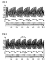
- FIG. 6 shows an example of a firing order in which a firing sequence period is 145 ms.
- FIG. 7 shows a firing order in which a firing frequency is 156 ms.
- the connection to the ignition electrode is interrupted or the distance of the ignition electrode to the ignition mass has exceeded a permissible value, this can be detected by an evaluation of the first dynamic feedback signal.
- the ignition sequence is shortened if there is an interruption or an impermissible distance.
- FIG. 8 shows a recorded in a test operation of the control unit 24 course of the measurement signals in the event of failure of a defective voltage generating unit 12 and a defective ignition device 14. Although the output voltage at the transformer 34 reaches the required ignition threshold, a firing order is not recognizable.
- FIG. 9 finally shows a dynamic feedback 30a, 30b of the voltage generating and measuring arrangement 10 in the event of a short circuit of Ionization electrode 16.
- the output voltage at the transformer 34 does not reach its normal value, which can also be recognized by the first dynamic feedback 30a, 30b.
- the measurement or the verification of the short circuit of the ionization electrode 16 can be carried out in particular even when the burner 22 is switched on.
- the control unit 24 compares a value of the ionization voltage detected via the first dynamic feedback 30a, 30b during normal operation with a predetermined, stored value which corresponds to an ionization voltage immediately after the production of the ionization electrode 16 or the flame monitoring device.
- a gradual deterioration or wear of the ionization electrode 16 can be recognized by a slow drop in the ionization voltage detected via the first dynamic feedback 30a, 30b.
- a warning signal is generated by the control unit 24 when the ionization voltage detected via the first dynamic feedback 30a, 30b falls below a critical value. The user is prompted by the warning signal to replace the ionization electrode 16. Alternatively, when the same or a second threshold is reached, an emergency shutdown of the burner 22 may occur.
Landscapes
- Engineering & Computer Science (AREA)
- Chemical & Material Sciences (AREA)
- Combustion & Propulsion (AREA)
- Mechanical Engineering (AREA)
- General Engineering & Computer Science (AREA)
- Other Investigation Or Analysis Of Materials By Electrical Means (AREA)
Priority Applications (1)
| Application Number | Priority Date | Filing Date | Title |
|---|---|---|---|
| PL08002271T PL1983264T3 (pl) | 2007-04-16 | 2008-02-07 | Urządzenie do monitorowania płomienia z układem do generowania i pomiaru napięcia; Sposób działania urządzenia |
Applications Claiming Priority (1)
| Application Number | Priority Date | Filing Date | Title |
|---|---|---|---|
| DE102007018122A DE102007018122B4 (de) | 2007-04-16 | 2007-04-16 | Flammenüberwachungsvorrichtung mit einer Spannungserzeugungs- und Messanordnung und Verfahren zum Überwachen eines Brenners mittels der Flammenüberwachungsvorrichtung |
Publications (4)
| Publication Number | Publication Date |
|---|---|
| EP1983264A2 true EP1983264A2 (fr) | 2008-10-22 |
| EP1983264A3 EP1983264A3 (fr) | 2014-02-19 |
| EP1983264B1 EP1983264B1 (fr) | 2017-08-23 |
| EP1983264B8 EP1983264B8 (fr) | 2017-09-27 |
Family
ID=39522199
Family Applications (1)
| Application Number | Title | Priority Date | Filing Date |
|---|---|---|---|
| EP08002271.8A Active EP1983264B8 (fr) | 2007-04-16 | 2008-02-07 | Dispositif de surveillance de flammes doté d'un système de mesure et de production de tension; procédé de fonctionnement pour le dispositif |
Country Status (3)
| Country | Link |
|---|---|
| EP (1) | EP1983264B8 (fr) |
| DE (1) | DE102007018122B4 (fr) |
| PL (1) | PL1983264T3 (fr) |
Cited By (6)
| Publication number | Priority date | Publication date | Assignee | Title |
|---|---|---|---|---|
| DE102010001307A1 (de) * | 2010-01-28 | 2011-08-18 | Viessmann Werke GmbH & Co KG, 35108 | Verfahren und Vorrichtung zur auf Ionisationsstrommessung basierenden Flammenerkennung |
| EP2682679A3 (fr) * | 2012-07-04 | 2014-08-13 | Vaillant GmbH | Procédé de surveillance d'un brûleur à gaz combustible |
| EP2843312A1 (fr) | 2013-08-30 | 2015-03-04 | Kübler GmbH | Procédé de détermination de l'état de maintenance des electrodes d'ionisation d'une installation de chauffage |
| WO2017081307A1 (fr) * | 2015-11-11 | 2017-05-18 | Viessmann Werke Gmbh & Co. Kg | Procédé de commande d'une unité de chauffage, unité de chauffage et produit de programme informatique destiné à mettre en œuvre le procédé de commande |
| EP3369994A1 (fr) * | 2017-03-03 | 2018-09-05 | Viessmann Werke GmbH & Co. KG | Procédé de détermination de l'origine d'un défaut d'allumage d'un brûleur d'une chaudière |
| WO2020020494A1 (fr) * | 2018-07-27 | 2020-01-30 | Ebm-Papst Landshut Gmbh | Procédé pour la surveillance et le réglage d'une flamme de brûleur d'un brûleur d'appareil de chauffage |
Families Citing this family (3)
| Publication number | Priority date | Publication date | Assignee | Title |
|---|---|---|---|---|
| DE102015210507A1 (de) * | 2015-06-09 | 2016-12-15 | Vaillant Gmbh | Flammenüberwachung |
| DE102019119206A1 (de) * | 2019-07-16 | 2021-01-21 | Vaillant Gmbh | Verfahren und Vorrichtung zur Anpassung der Empfindlichkeit eines Detektors zur Überwachung einer Flamme in einem Heizgerät |
| WO2023217328A1 (fr) * | 2022-05-11 | 2023-11-16 | Viessmann Climate Solutions Se | Procédé pour faire fonctionner un emsemble brûleur |
Citations (1)
| Publication number | Priority date | Publication date | Assignee | Title |
|---|---|---|---|---|
| DE10025769A1 (de) | 2000-05-12 | 2001-11-15 | Siemens Building Tech Ag | Regeleinrichtung für einen Brenner |
Family Cites Families (10)
| Publication number | Priority date | Publication date | Assignee | Title |
|---|---|---|---|---|
| US3853455A (en) * | 1973-09-24 | 1974-12-10 | Kidde & Co Walter | Burner control apparatus |
| NL8401173A (nl) * | 1984-04-12 | 1985-11-01 | Philips Nv | Vlambeveiligingsschakeling. |
| JPS625014A (ja) * | 1985-06-28 | 1987-01-12 | Matsushita Electric Ind Co Ltd | 燃焼検出装置 |
| EP0334027B1 (fr) * | 1988-03-25 | 1994-04-27 | Hartmann & Braun Leipzig GmbH | Circuit dynamique autosurveillant pour détecteur de flamme |
| DD276409A3 (de) * | 1988-03-25 | 1990-02-28 | Geraete & Regler Werke Veb | Schaltungsanordnung zur dynamischen eigenueberwachung von flammenwaechtern |
| DE4309454C2 (de) * | 1993-03-24 | 1997-03-06 | Dungs Karl Gmbh & Co | Ionisationsflammenwächter |
| US5472336A (en) * | 1993-05-28 | 1995-12-05 | Honeywell Inc. | Flame rectification sensor employing pulsed excitation |
| EP0908679A1 (fr) * | 1997-10-10 | 1999-04-14 | Electrowatt Technology Innovation AG | Circuit de surveillance de flammes |
| DE10247168B4 (de) * | 2002-10-10 | 2004-09-09 | Karl Dungs Gmbh & Co. Kg | Flammenwächter mit Selbsttestfunktion und Verfahren zur Betriebsüberwachung |
| EP1719947B1 (fr) * | 2005-05-06 | 2010-04-14 | Siemens Building Technologies HVAC Products GmbH | Procédé et dispositif de contrôle de flammes |
-
2007
- 2007-04-16 DE DE102007018122A patent/DE102007018122B4/de not_active Expired - Fee Related
-
2008
- 2008-02-07 PL PL08002271T patent/PL1983264T3/pl unknown
- 2008-02-07 EP EP08002271.8A patent/EP1983264B8/fr active Active
Patent Citations (1)
| Publication number | Priority date | Publication date | Assignee | Title |
|---|---|---|---|---|
| DE10025769A1 (de) | 2000-05-12 | 2001-11-15 | Siemens Building Tech Ag | Regeleinrichtung für einen Brenner |
Cited By (9)
| Publication number | Priority date | Publication date | Assignee | Title |
|---|---|---|---|---|
| DE102010001307A1 (de) * | 2010-01-28 | 2011-08-18 | Viessmann Werke GmbH & Co KG, 35108 | Verfahren und Vorrichtung zur auf Ionisationsstrommessung basierenden Flammenerkennung |
| DE102010001307B4 (de) * | 2010-01-28 | 2013-12-24 | Viessmann Werke Gmbh & Co Kg | Verfahren und Vorrichtung zur auf Ionisationsstrommessung basierenden Flammenerkennung sowie Flammenüberwachungssystem |
| EP2682679A3 (fr) * | 2012-07-04 | 2014-08-13 | Vaillant GmbH | Procédé de surveillance d'un brûleur à gaz combustible |
| EP2843312A1 (fr) | 2013-08-30 | 2015-03-04 | Kübler GmbH | Procédé de détermination de l'état de maintenance des electrodes d'ionisation d'une installation de chauffage |
| DE102013014379A1 (de) | 2013-08-30 | 2015-03-05 | Kübler Gmbh | Verfahren zur Bestimmung des Wartungszustands einer Heizungsanlage |
| WO2017081307A1 (fr) * | 2015-11-11 | 2017-05-18 | Viessmann Werke Gmbh & Co. Kg | Procédé de commande d'une unité de chauffage, unité de chauffage et produit de programme informatique destiné à mettre en œuvre le procédé de commande |
| US10605458B2 (en) | 2015-11-11 | 2020-03-31 | Viessmann Werke Gmbh & Co. Kg | Method for controlling a heating unit as well as a heating unit and a computer program product for carrying out the control method |
| EP3369994A1 (fr) * | 2017-03-03 | 2018-09-05 | Viessmann Werke GmbH & Co. KG | Procédé de détermination de l'origine d'un défaut d'allumage d'un brûleur d'une chaudière |
| WO2020020494A1 (fr) * | 2018-07-27 | 2020-01-30 | Ebm-Papst Landshut Gmbh | Procédé pour la surveillance et le réglage d'une flamme de brûleur d'un brûleur d'appareil de chauffage |
Also Published As
| Publication number | Publication date |
|---|---|
| DE102007018122A1 (de) | 2008-10-23 |
| EP1983264B1 (fr) | 2017-08-23 |
| EP1983264A3 (fr) | 2014-02-19 |
| DE102007018122B4 (de) | 2013-10-17 |
| EP1983264B8 (fr) | 2017-09-27 |
| PL1983264T3 (pl) | 2018-01-31 |
Similar Documents
| Publication | Publication Date | Title |
|---|---|---|
| EP1983264B1 (fr) | Dispositif de surveillance de flammes doté d'un système de mesure et de production de tension; procédé de fonctionnement pour le dispositif | |
| EP2357410B1 (fr) | Procédé et brûleur avec détection de flammes basée sur une mesure du courant d'ionisation | |
| EP1154203B2 (fr) | Dispositif de mesure pour une flamme | |
| EP1719947B1 (fr) | Procédé et dispositif de contrôle de flammes | |
| EP2014985A2 (fr) | Procédé de réglage du rapport air/carburant d'un brûleur fonctionnant au gaz | |
| DE19917268A1 (de) | Verfahren zum Überprüfen eines elektromagnetischen Durchflußmessers und elektromagnetische Durchflußmesseranordnung | |
| EP2439451B1 (fr) | Dispositif de détection de la présence d'une flamme | |
| EP1021684A1 (fr) | Procede et dispositif pour la surveillance d'une flamme | |
| EP2408569B2 (fr) | Procédé de surveillance et dispositif de surveillance pour une installation de revêtement électrostatique | |
| EP0525345B2 (fr) | Dispositif et procédé de surveillance d'une flamme | |
| DE102005023295A1 (de) | Schaltung zur Ansteuerung und Überwachung eines Lichtsignals | |
| EP2240677A1 (fr) | Procédé pour contrôler au moins une bougie-crayon de préchauffage d'un moteur à combustion interne et dispositif correspondant | |
| DE19631821C2 (de) | Verfahren und Einrichtung zur Sicherheits-Flammenüberwachung bei einem Gasbrenner | |
| DE102010044845B3 (de) | Verfahren zum Betreiben einer HF-Zündanlage | |
| EP3869102B1 (fr) | Procédé et dispositif de diagnostic de panne sur un dispositif automatique de chauffe | |
| DE102015222263B3 (de) | Verfahren und vorrichtung zur flammensignalerfassung | |
| DE10012542A1 (de) | Einrichtung zur Überprüfung der Auswerteschaltung einer automatischen Schaltung für Beleuchtungseinrichtungen bei Fahrzeugen | |
| EP3885653A1 (fr) | Dispositif de commutation et procédé de surveillance d'une flamme de brûleur | |
| EP3106753B1 (fr) | Surveillance de flammes | |
| DE102004051083B3 (de) | Flammenwächter | |
| EP4148325B1 (fr) | Procédé et dispositif de détection de la présence des flammes dans une chambre de combustion lors d'une modulation d'un appareil chauffant | |
| DE1951438B2 (de) | Einrichtung zur gleichzeitigen Überwachung mehrerer Flammen | |
| EP4092324A1 (fr) | Procédé de surveillance du fonctionnement d'un appareil chauffant, appareil chauffant, ainsi que programme informatique et support lisible par ordinateur | |
| EP3369994A1 (fr) | Procédé de détermination de l'origine d'un défaut d'allumage d'un brûleur d'une chaudière | |
| EP1390668B1 (fr) | Dispositif de controle de flamme |
Legal Events
| Date | Code | Title | Description |
|---|---|---|---|
| PUAI | Public reference made under article 153(3) epc to a published international application that has entered the european phase |
Free format text: ORIGINAL CODE: 0009012 |
|
| AK | Designated contracting states |
Kind code of ref document: A2 Designated state(s): AT BE BG CH CY CZ DE DK EE ES FI FR GB GR HR HU IE IS IT LI LT LU LV MC MT NL NO PL PT RO SE SI SK TR |
|
| AX | Request for extension of the european patent |
Extension state: AL BA MK RS |
|
| PUAL | Search report despatched |
Free format text: ORIGINAL CODE: 0009013 |
|
| AK | Designated contracting states |
Kind code of ref document: A3 Designated state(s): AT BE BG CH CY CZ DE DK EE ES FI FR GB GR HR HU IE IS IT LI LT LU LV MC MT NL NO PL PT RO SE SI SK TR |
|
| AX | Request for extension of the european patent |
Extension state: AL BA MK RS |
|
| RIC1 | Information provided on ipc code assigned before grant |
Ipc: F23N 5/24 20060101ALI20140113BHEP Ipc: F23N 5/12 20060101AFI20140113BHEP |
|
| 17P | Request for examination filed |
Effective date: 20140819 |
|
| RAX | Requested extension states of the european patent have changed |
Extension state: AL Extension state: RS Extension state: MK Extension state: BA Payment date: 20140819 |
|
| RBV | Designated contracting states (corrected) |
Designated state(s): AT BE BG CH CY CZ DE DK EE ES FI FR GB GR HR HU IE IS IT LI LT LU LV MC MT NL NO PL PT RO SE SI SK TR |
|
| AKX | Designation fees paid |
Designated state(s): AT BE BG CH CY CZ DE DK EE ES FI FR GB GR HR HU IE IS IT LI LT LU LV MC MT NL NO PL PT RO SE SI SK TR |
|
| AXX | Extension fees paid |
Extension state: BA Payment date: 20140819 |
|
| GRAP | Despatch of communication of intention to grant a patent |
Free format text: ORIGINAL CODE: EPIDOSNIGR1 |
|
| INTG | Intention to grant announced |
Effective date: 20170228 |
|
| GRAS | Grant fee paid |
Free format text: ORIGINAL CODE: EPIDOSNIGR3 |
|
| GRAA | (expected) grant |
Free format text: ORIGINAL CODE: 0009210 |
|
| AK | Designated contracting states |
Kind code of ref document: B1 Designated state(s): AT BE BG CH CY CZ DE DK EE ES FI FR GB GR HR HU IE IS IT LI LT LU LV MC MT NL NO PL PT RO SE SI SK TR |
|
| AX | Request for extension of the european patent |
Extension state: BA |
|
| REG | Reference to a national code |
Ref country code: GB Ref legal event code: FG4D Free format text: NOT ENGLISH |
|
| REG | Reference to a national code |
Ref country code: CH Ref legal event code: EP |
|
| REG | Reference to a national code |
Ref country code: AT Ref legal event code: REF Ref document number: 921752 Country of ref document: AT Kind code of ref document: T Effective date: 20170915 |
|
| RAP2 | Party data changed (patent owner data changed or rights of a patent transferred) |
Owner name: VIESSMANN WERKE GMBH & CO. KG |
|
| REG | Reference to a national code |
Ref country code: IE Ref legal event code: FG4D Free format text: LANGUAGE OF EP DOCUMENT: GERMAN |
|
| REG | Reference to a national code |
Ref country code: DE Ref legal event code: R096 Ref document number: 502008015543 Country of ref document: DE |
|
| REG | Reference to a national code |
Ref country code: NL Ref legal event code: MP Effective date: 20170823 |
|
| REG | Reference to a national code |
Ref country code: LT Ref legal event code: MG4D |
|
| PG25 | Lapsed in a contracting state [announced via postgrant information from national office to epo] |
Ref country code: FI Free format text: LAPSE BECAUSE OF FAILURE TO SUBMIT A TRANSLATION OF THE DESCRIPTION OR TO PAY THE FEE WITHIN THE PRESCRIBED TIME-LIMIT Effective date: 20170823 Ref country code: SE Free format text: LAPSE BECAUSE OF FAILURE TO SUBMIT A TRANSLATION OF THE DESCRIPTION OR TO PAY THE FEE WITHIN THE PRESCRIBED TIME-LIMIT Effective date: 20170823 Ref country code: NL Free format text: LAPSE BECAUSE OF FAILURE TO SUBMIT A TRANSLATION OF THE DESCRIPTION OR TO PAY THE FEE WITHIN THE PRESCRIBED TIME-LIMIT Effective date: 20170823 Ref country code: NO Free format text: LAPSE BECAUSE OF FAILURE TO SUBMIT A TRANSLATION OF THE DESCRIPTION OR TO PAY THE FEE WITHIN THE PRESCRIBED TIME-LIMIT Effective date: 20171123 Ref country code: LT Free format text: LAPSE BECAUSE OF FAILURE TO SUBMIT A TRANSLATION OF THE DESCRIPTION OR TO PAY THE FEE WITHIN THE PRESCRIBED TIME-LIMIT Effective date: 20170823 Ref country code: HR Free format text: LAPSE BECAUSE OF FAILURE TO SUBMIT A TRANSLATION OF THE DESCRIPTION OR TO PAY THE FEE WITHIN THE PRESCRIBED TIME-LIMIT Effective date: 20170823 |
|
| REG | Reference to a national code |
Ref country code: FR Ref legal event code: PLFP Year of fee payment: 11 |
|
| PG25 | Lapsed in a contracting state [announced via postgrant information from national office to epo] |
Ref country code: BG Free format text: LAPSE BECAUSE OF FAILURE TO SUBMIT A TRANSLATION OF THE DESCRIPTION OR TO PAY THE FEE WITHIN THE PRESCRIBED TIME-LIMIT Effective date: 20171123 Ref country code: LV Free format text: LAPSE BECAUSE OF FAILURE TO SUBMIT A TRANSLATION OF THE DESCRIPTION OR TO PAY THE FEE WITHIN THE PRESCRIBED TIME-LIMIT Effective date: 20170823 Ref country code: IS Free format text: LAPSE BECAUSE OF FAILURE TO SUBMIT A TRANSLATION OF THE DESCRIPTION OR TO PAY THE FEE WITHIN THE PRESCRIBED TIME-LIMIT Effective date: 20171223 Ref country code: GR Free format text: LAPSE BECAUSE OF FAILURE TO SUBMIT A TRANSLATION OF THE DESCRIPTION OR TO PAY THE FEE WITHIN THE PRESCRIBED TIME-LIMIT Effective date: 20171124 Ref country code: ES Free format text: LAPSE BECAUSE OF FAILURE TO SUBMIT A TRANSLATION OF THE DESCRIPTION OR TO PAY THE FEE WITHIN THE PRESCRIBED TIME-LIMIT Effective date: 20170823 |
|
| PG25 | Lapsed in a contracting state [announced via postgrant information from national office to epo] |
Ref country code: RO Free format text: LAPSE BECAUSE OF FAILURE TO SUBMIT A TRANSLATION OF THE DESCRIPTION OR TO PAY THE FEE WITHIN THE PRESCRIBED TIME-LIMIT Effective date: 20170823 Ref country code: DK Free format text: LAPSE BECAUSE OF FAILURE TO SUBMIT A TRANSLATION OF THE DESCRIPTION OR TO PAY THE FEE WITHIN THE PRESCRIBED TIME-LIMIT Effective date: 20170823 Ref country code: CZ Free format text: LAPSE BECAUSE OF FAILURE TO SUBMIT A TRANSLATION OF THE DESCRIPTION OR TO PAY THE FEE WITHIN THE PRESCRIBED TIME-LIMIT Effective date: 20170823 |
|
| REG | Reference to a national code |
Ref country code: DE Ref legal event code: R097 Ref document number: 502008015543 Country of ref document: DE |
|
| PG25 | Lapsed in a contracting state [announced via postgrant information from national office to epo] |
Ref country code: EE Free format text: LAPSE BECAUSE OF FAILURE TO SUBMIT A TRANSLATION OF THE DESCRIPTION OR TO PAY THE FEE WITHIN THE PRESCRIBED TIME-LIMIT Effective date: 20170823 Ref country code: SK Free format text: LAPSE BECAUSE OF FAILURE TO SUBMIT A TRANSLATION OF THE DESCRIPTION OR TO PAY THE FEE WITHIN THE PRESCRIBED TIME-LIMIT Effective date: 20170823 |
|
| PLBE | No opposition filed within time limit |
Free format text: ORIGINAL CODE: 0009261 |
|
| STAA | Information on the status of an ep patent application or granted ep patent |
Free format text: STATUS: NO OPPOSITION FILED WITHIN TIME LIMIT |
|
| 26N | No opposition filed |
Effective date: 20180524 |
|
| PG25 | Lapsed in a contracting state [announced via postgrant information from national office to epo] |
Ref country code: SI Free format text: LAPSE BECAUSE OF FAILURE TO SUBMIT A TRANSLATION OF THE DESCRIPTION OR TO PAY THE FEE WITHIN THE PRESCRIBED TIME-LIMIT Effective date: 20170823 |
|
| REG | Reference to a national code |
Ref country code: CH Ref legal event code: PL |
|
| PG25 | Lapsed in a contracting state [announced via postgrant information from national office to epo] |
Ref country code: MC Free format text: LAPSE BECAUSE OF FAILURE TO SUBMIT A TRANSLATION OF THE DESCRIPTION OR TO PAY THE FEE WITHIN THE PRESCRIBED TIME-LIMIT Effective date: 20170823 Ref country code: MT Free format text: LAPSE BECAUSE OF FAILURE TO SUBMIT A TRANSLATION OF THE DESCRIPTION OR TO PAY THE FEE WITHIN THE PRESCRIBED TIME-LIMIT Effective date: 20170823 |
|
| GBPC | Gb: european patent ceased through non-payment of renewal fee |
Effective date: 20180207 |
|
| REG | Reference to a national code |
Ref country code: IE Ref legal event code: MM4A |
|
| PG25 | Lapsed in a contracting state [announced via postgrant information from national office to epo] |
Ref country code: LI Free format text: LAPSE BECAUSE OF NON-PAYMENT OF DUE FEES Effective date: 20180228 Ref country code: CH Free format text: LAPSE BECAUSE OF NON-PAYMENT OF DUE FEES Effective date: 20180228 Ref country code: LU Free format text: LAPSE BECAUSE OF NON-PAYMENT OF DUE FEES Effective date: 20180207 |
|
| PG25 | Lapsed in a contracting state [announced via postgrant information from national office to epo] |
Ref country code: IE Free format text: LAPSE BECAUSE OF NON-PAYMENT OF DUE FEES Effective date: 20180207 |
|
| PG25 | Lapsed in a contracting state [announced via postgrant information from national office to epo] |
Ref country code: GB Free format text: LAPSE BECAUSE OF NON-PAYMENT OF DUE FEES Effective date: 20180207 |
|
| PG25 | Lapsed in a contracting state [announced via postgrant information from national office to epo] |
Ref country code: TR Free format text: LAPSE BECAUSE OF FAILURE TO SUBMIT A TRANSLATION OF THE DESCRIPTION OR TO PAY THE FEE WITHIN THE PRESCRIBED TIME-LIMIT Effective date: 20170823 |
|
| PG25 | Lapsed in a contracting state [announced via postgrant information from national office to epo] |
Ref country code: HU Free format text: LAPSE BECAUSE OF FAILURE TO SUBMIT A TRANSLATION OF THE DESCRIPTION OR TO PAY THE FEE WITHIN THE PRESCRIBED TIME-LIMIT; INVALID AB INITIO Effective date: 20080207 Ref country code: PT Free format text: LAPSE BECAUSE OF FAILURE TO SUBMIT A TRANSLATION OF THE DESCRIPTION OR TO PAY THE FEE WITHIN THE PRESCRIBED TIME-LIMIT Effective date: 20170823 |
|
| PG25 | Lapsed in a contracting state [announced via postgrant information from national office to epo] |
Ref country code: CY Free format text: LAPSE BECAUSE OF FAILURE TO SUBMIT A TRANSLATION OF THE DESCRIPTION OR TO PAY THE FEE WITHIN THE PRESCRIBED TIME-LIMIT Effective date: 20170823 |
|
| PGFP | Annual fee paid to national office [announced via postgrant information from national office to epo] |
Ref country code: AT Payment date: 20220215 Year of fee payment: 15 |
|
| PGFP | Annual fee paid to national office [announced via postgrant information from national office to epo] |
Ref country code: PL Payment date: 20220127 Year of fee payment: 15 Ref country code: IT Payment date: 20220228 Year of fee payment: 15 Ref country code: FR Payment date: 20220221 Year of fee payment: 15 Ref country code: BE Payment date: 20220216 Year of fee payment: 15 |
|
| P01 | Opt-out of the competence of the unified patent court (upc) registered |
Effective date: 20230515 |
|
| REG | Reference to a national code |
Ref country code: AT Ref legal event code: MM01 Ref document number: 921752 Country of ref document: AT Kind code of ref document: T Effective date: 20230207 |
|
| REG | Reference to a national code |
Ref country code: BE Ref legal event code: MM Effective date: 20230228 |
|
| PG25 | Lapsed in a contracting state [announced via postgrant information from national office to epo] |
Ref country code: AT Free format text: LAPSE BECAUSE OF NON-PAYMENT OF DUE FEES Effective date: 20230207 |
|
| PG25 | Lapsed in a contracting state [announced via postgrant information from national office to epo] |
Ref country code: IT Free format text: LAPSE BECAUSE OF NON-PAYMENT OF DUE FEES Effective date: 20230207 Ref country code: FR Free format text: LAPSE BECAUSE OF NON-PAYMENT OF DUE FEES Effective date: 20230228 |
|
| PG25 | Lapsed in a contracting state [announced via postgrant information from national office to epo] |
Ref country code: BE Free format text: LAPSE BECAUSE OF NON-PAYMENT OF DUE FEES Effective date: 20230228 |
|
| PGFP | Annual fee paid to national office [announced via postgrant information from national office to epo] |
Ref country code: DE Payment date: 20240229 Year of fee payment: 17 |
|
| PG25 | Lapsed in a contracting state [announced via postgrant information from national office to epo] |
Ref country code: PL Free format text: LAPSE BECAUSE OF NON-PAYMENT OF DUE FEES Effective date: 20230207 |
|
| PG25 | Lapsed in a contracting state [announced via postgrant information from national office to epo] |
Ref country code: PL Free format text: LAPSE BECAUSE OF NON-PAYMENT OF DUE FEES Effective date: 20230207 |
|
| REG | Reference to a national code |
Ref country code: DE Ref legal event code: R119 Ref document number: 502008015543 Country of ref document: DE |
|
| PG25 | Lapsed in a contracting state [announced via postgrant information from national office to epo] |
Ref country code: DE Free format text: LAPSE BECAUSE OF NON-PAYMENT OF DUE FEES Effective date: 20250902 |