EP1983264A2 - Flame monitoring device with voltage generator and voltage measuring device - Google Patents
Flame monitoring device with voltage generator and voltage measuring device Download PDFInfo
- Publication number
- EP1983264A2 EP1983264A2 EP08002271A EP08002271A EP1983264A2 EP 1983264 A2 EP1983264 A2 EP 1983264A2 EP 08002271 A EP08002271 A EP 08002271A EP 08002271 A EP08002271 A EP 08002271A EP 1983264 A2 EP1983264 A2 EP 1983264A2
- Authority
- EP
- European Patent Office
- Prior art keywords
- voltage
- ionization
- monitoring device
- flame
- flame monitoring
- Prior art date
- Legal status (The legal status is an assumption and is not a legal conclusion. Google has not performed a legal analysis and makes no representation as to the accuracy of the status listed.)
- Granted
Links
- 238000012806 monitoring device Methods 0.000 title claims abstract description 33
- 238000012544 monitoring process Methods 0.000 claims abstract description 12
- 230000007257 malfunction Effects 0.000 claims abstract description 7
- 238000000034 method Methods 0.000 claims abstract description 7
- 238000010304 firing Methods 0.000 claims description 18
- 238000012360 testing method Methods 0.000 claims description 9
- 239000000446 fuel Substances 0.000 claims description 7
- 238000005259 measurement Methods 0.000 description 5
- 238000011156 evaluation Methods 0.000 description 4
- 230000002950 deficient Effects 0.000 description 3
- 238000010586 diagram Methods 0.000 description 2
- 238000012423 maintenance Methods 0.000 description 2
- 230000002035 prolonged effect Effects 0.000 description 2
- 230000036962 time dependent Effects 0.000 description 2
- 230000000712 assembly Effects 0.000 description 1
- 238000000429 assembly Methods 0.000 description 1
- 230000005540 biological transmission Effects 0.000 description 1
- 239000000969 carrier Substances 0.000 description 1
- 230000006866 deterioration Effects 0.000 description 1
- 238000011161 development Methods 0.000 description 1
- 239000011159 matrix material Substances 0.000 description 1
- 238000012795 verification Methods 0.000 description 1
Images


Classifications
-
- F—MECHANICAL ENGINEERING; LIGHTING; HEATING; WEAPONS; BLASTING
- F23—COMBUSTION APPARATUS; COMBUSTION PROCESSES
- F23N—REGULATING OR CONTROLLING COMBUSTION
- F23N5/00—Systems for controlling combustion
- F23N5/02—Systems for controlling combustion using devices responsive to thermal changes or to thermal expansion of a medium
- F23N5/12—Systems for controlling combustion using devices responsive to thermal changes or to thermal expansion of a medium using ionisation-sensitive elements, i.e. flame rods
- F23N5/123—Systems for controlling combustion using devices responsive to thermal changes or to thermal expansion of a medium using ionisation-sensitive elements, i.e. flame rods using electronic means
-
- F—MECHANICAL ENGINEERING; LIGHTING; HEATING; WEAPONS; BLASTING
- F23—COMBUSTION APPARATUS; COMBUSTION PROCESSES
- F23N—REGULATING OR CONTROLLING COMBUSTION
- F23N5/00—Systems for controlling combustion
- F23N5/24—Preventing development of abnormal or undesired conditions, i.e. safety arrangements
- F23N5/242—Preventing development of abnormal or undesired conditions, i.e. safety arrangements using electronic means
-
- F—MECHANICAL ENGINEERING; LIGHTING; HEATING; WEAPONS; BLASTING
- F23—COMBUSTION APPARATUS; COMBUSTION PROCESSES
- F23N—REGULATING OR CONTROLLING COMBUSTION
- F23N2229/00—Flame sensors
- F23N2229/12—Flame sensors with flame rectification current detecting means
-
- F—MECHANICAL ENGINEERING; LIGHTING; HEATING; WEAPONS; BLASTING
- F23—COMBUSTION APPARATUS; COMBUSTION PROCESSES
- F23N—REGULATING OR CONTROLLING COMBUSTION
- F23N2231/00—Fail safe
- F23N2231/10—Fail safe for component failures
Definitions
- the invention relates to a flame monitoring device with a voltage generating and measuring arrangement according to the preamble of claim 1 and a method for monitoring a burner by means of a flame monitoring device according to the preamble of claim 10.
- a flame monitoring device is known with a voltage generating and measuring arrangement in which an air-gas ratio of a burner flame is controlled via an ionization electrode.
- Ionization electrodes are often used to monitor a gas flame and use the rectifying property of the gas flame. For this purpose, an alternating voltage is applied to the ionization electrode and an ionization current is measured at the ionization electrode. If there is no flame or the flame is extinguished, the ionization current stops, allowing the flow of gas to be shut off to prevent the risk of unburned, escaping gas. While such a safety monitoring requires only a binary output signal is in the DE 100 25 769 A1 proposed to use a dynamic feedback of the ionization electrode for controlling the flame characteristics, in particular for controlling the air / fuel ratio.
- the invention is in particular the object of a generic flame monitoring device or a method for operating such a flame monitoring device to provide, in which or which not only the flame but also the flame monitoring device itself can be monitored.
- the invention relates to a flame monitoring device with a voltage generating and measuring arrangement, which comprises a voltage generating unit for generating an ignition voltage for operating an igniter of a burner and / or generating an ionization voltage of an ionization electrode for monitoring a flame of the burner and a measuring unit for measuring a through the Ionisationsweakened generated ionization. Furthermore, the flame monitoring device comprises a control unit for controlling the voltage generating unit and for evaluating the measured values of the measuring unit.
- control unit is designed to detect at least one dynamic feedback of the voltage generating and measuring arrangement and to evaluate it for detecting a malfunction of an element of the voltage generating and measuring arrangement.
- Safety-relevant components or assemblies of the voltage generating and measuring arrangement should be referred to as elements of the voltage generating and measuring arrangement.
- the voltage generating unit, the ionization electrode, the ignition device and the measuring unit come into consideration as elements to be monitored.
- the dynamic feedback of the voltage generating and measuring arrangement is used for monitoring the same, so that a reliability of a burner with a generic flame monitoring device can be significantly increased.
- dynamic feedback is to be understood as meaning, in particular, a time-dependent signal having a continuous or quasi-continuous value range which is a parameter for a voltage or a current in the voltage generation and power supply Measuring arrangement forms.
- the control unit which forms from the dynamic feedback a parameter for an actually applied ignition voltage, or that the dynamic feedback is such a parameter.
- the dynamic feedback may be directly proportional to the actual applied ignition voltage or may be a digital signal that encodes a measured ignition voltage.
- a technically simple evaluation of the dynamic feedback can be made possible if the dynamic feedback is a pulse-width-modulated signal in which a duty cycle codes the actually applied ignition voltage.
- the actual applied ignition voltage can be tapped by means of a voltage measuring arrangement on an ignition coil of the ignition device.
- the dynamic feedback forms a parameter for an actually applied ionization voltage.
- the ionization voltage can be monitored and measuring errors of the measuring unit, which are caused by an incorrectly determined ionization voltage, can be avoided.
- the voltage generating unit comprises a variable voltage source for generating both the ignition voltage and the ionization voltage
- the voltage generating unit comprises a variable voltage source for generating both the ignition voltage and the ionization voltage
- both the monitoring of the ionization voltage and the monitoring of the ignition voltage can be carried out by a single voltage measuring arrangement.
- control unit is designed to compare a measured value detected by the measuring unit with at least one predetermined upper or lower threshold value and to generate an error signal, if the reading exceeds the upper threshold or is less than the lower threshold.
- the error signal can be used as a warning signal to a user and / or to generate an emergency shutdown of the burner.
- control unit is designed to generate and measure an ignition voltage when the fuel supply is switched off in a test mode, the ignition voltage can be measured separately in reproducible conditions without disturbing influences of a burner flame.
- control unit determines a firing rate when the fuel supply is switched off in a test mode.
- control unit is designed to receive and process the dynamic feedback in the form of a pulse-width-modulated signal, the evaluation can be carried out by means of a simple low-pass filter and information loss during transmission can be largely avoided.
- Quiet continuous operation can be achieved by a current regulator for generating a stable ionization voltage can be achieved.
- control unit is designed to detect at least a first dynamic feedback of the voltage generating unit and a second dynamic feedback of the measuring unit and to use for detecting a malfunction of the voltage generating unit or the measuring unit.
- the invention relates to a method for monitoring a burner by means of a flame monitoring device, wherein the flame is monitored by means of a Ionisationsstrom generated by an ionization electrode.
- a dynamic response of the flame monitoring device is detected and a malfunction of at least one element of the flame monitoring device is detected as a function of the dynamic feedback.
- FIG. 1 schematically shows a flame monitoring device for monitoring a burner 22 with a voltage generating and measuring arrangement 10.
- the voltage generating and measuring arrangement 10 comprises a voltage generating unit 12 for generating an ignition voltage, which can be used to operate an ignition device 14 with a firing mass.
- the voltage generating unit 12 serves to generate a Ionization voltage of an ionization electrode 16 for monitoring a flame 18 of the burner 22.
- the voltage generating and measuring arrangement 10 comprises a measuring unit 20 for measuring an ionization current generated by the ionization voltage.
- the ionization voltage is an AC voltage that drops across the flame 18 of the burner 22.
- the flame 18 is a gas flame and has a rectifying property, since there are 18 carriers of different polarities in the flame, the mobility of which differs greatly.
- the ionization current from or to the ionization electrode 16 flows predominantly during a half period of the ionization voltage, while the latter has a certain sign.
- the ionization current also comes to a standstill, which can be measured by the measuring unit 20. If this happens, appropriate safety measures can be taken, for example, the gas supply can be switched off.
- the evaluation of the signals of the measuring unit 20 and the control of the voltage generating unit 12 takes place in a control unit 24 of the flame monitoring device.
- the control unit 24 controls the voltage generation unit 12 by means of a first, pulse-width-modulated control signal 26a, which is transmitted via a first signal line 28a from the control unit 24 to the voltage generation unit 12.
- the control unit 24 transmits a second, pulse-width-modulated control signal 26b to the measuring unit 20 via a second signal line 28b.
- the second control signal 26b is primarily used to specify a measuring frequency, but can also be used to control operating parameters of the measuring unit 20.
- the control unit 24 receives a first dynamic feedback 30a from the voltage generating unit 12 of the voltage generating and measuring arrangement 10.
- the control unit 24 receives a second dynamic feedback 30b from the measuring unit 20.
- the first dynamic feedback 30a and the second dynamic feedback 30b are each pulse width modulated signals, wherein a duty cycle of the first dynamic feedback 30a and the second dynamic feedback 30b has a continuous range of values and is time-dependent.
- the value of the duty cycle encodes an actually generated voltage in the voltage generation unit 12 or a voltage measured by the measurement unit 20 or an ionization current measured by the measurement unit 20, as described in greater detail below.
- the control unit 24 is designed to recognize a malfunction of an element or component of the voltage generating and measuring arrangement 10 from the first dynamic feedback 30a and the second dynamic feedback 30b and to evaluate the first dynamic feedback 30a and the second dynamic feedback 30b.
- the duty cycle of the first dynamic feedback 30a is a characteristic for an actual applied ignition voltage
- the duty cycle of the second dynamic response 30b or of the second pulse width modulated signal is a parameter for an ionization voltage actually applied or for an actually flowing ionization current.
- FIG. 2 shows a circuit diagram of the voltage generating unit 12 from FIG. 1 in a more detailed presentation.
- the first pulse width modulated control signal 26a of the control unit 24 is applied, which has a carrier frequency of 22 kHz in a preferred embodiment.
- a second terminal 32b is connected to the third signal line 28a so that the control unit 24 receives the first dynamic feedback 30a via the second terminal 32b.
- the height of an output voltage at a transformer 34 can be set via the first pulse-width-modulated control signal 26a.
- the controller 24 may increase the positive duty cycle of the first pulse width modulated control signal 26a to increase the output voltage and power at the transmitter 34. Increasing the duty cycle, the voltage at the transformer 34 increases.
- the voltage generating unit 12 includes a current regulator 36, which ensures a stable output voltage at the operating point.
- FIG. 3 shows a circuit diagram of the measuring unit 20 of the voltage generating and measuring arrangement 10 from FIG. 1 in a more detailed view.
- a first contact point 38a is connected to the ionization electrode 16 such that an ionization current at the contact point 38a generates a pulse width modulated signal forming the second dynamic feedback 30b at two outputs.
- the size of the duty cycle of the pulse-width-modulated signal generated at the two outputs is a parameter for the ionization current.
- the voltage generated at the transformer 34 then leads to ignition of the ignition device 14 when it exceeds an ignition voltage.
- the voltage at the transformer 34 becomes lower, it generates an ionization voltage at the ionization electrode 16 and therefore causes a measurable ionization current to flow in the matrix burner burner 22 when the flame 18 is present.
- the value of the voltage applied to the transformer 34 therefore decides whether the voltage is used as the ignition voltage or as the ionization voltage. Therefore, the transformer 34 of the voltage generating unit 12 forms a variable voltage source for generating both Ignition voltage and the ionization voltage.
- the variable voltage source is, as discussed above, adjustable by the choice of frequency and / or by the selection of a duty cycle of the first control signal 26a, 26b.
- control unit 24 compares the measured value encoded in the second dynamic feedback 30b detected by the measuring unit 20 and the value encoded in the first dynamic feedback 30a in different operating modes having different upper thresholds and lower thresholds. If the measurement or value exceeds the respective upper threshold value or is smaller than the lower threshold value, the control unit 24 generates an error signal and optionally initiates an emergency shutdown of the burner 22.
- the control unit 24 is a programmable arithmetic unit equipped with software that controls a test operation of the flame monitoring device outside normal operation of the burner 22. In the test mode, the control unit 24 generates and measures an ignition voltage or ionization voltage via the first control signal 26.
- FIG. 4 shows the time course of the first dynamic feedback 30a of the voltage generating and measuring arrangement 10 in test mode, ie when the fuel supply is switched off, in the case of a short circuit of an ignition electrode. If the ignition electrode is short-circuited, no voltage can build up on the transformer 34 despite the controlled AC voltage, so that the dynamic feedback 30a, 30b assumes a constant value.
- FIG. 5 shows the output voltage at the transformer 34 and the first dynamic feedback 30a, 30b at normal ignition. It can be seen that the amplitude of the voltage applied to the transformer 34 AC voltage periodically increases to discharge in the ignition when it reaches an ignition threshold.
- the first dynamic feedback 30a is permanently at about 3 volts, varies during normal ignition the ignition voltage encoded in the first dynamic feedback 30a by about 1.5 volts.
- the control unit 24 detects in the test mode when the fuel supply is switched off a firing repetition or firing sequence period, in order to draw conclusions about a state of wear of the ignition electrode.
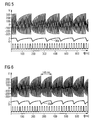
- FIG. 6 shows an example of a firing order in which a firing sequence period is 145 ms.
- FIG. 7 shows a firing order in which a firing frequency is 156 ms.
- the connection to the ignition electrode is interrupted or the distance of the ignition electrode to the ignition mass has exceeded a permissible value, this can be detected by an evaluation of the first dynamic feedback signal.
- the ignition sequence is shortened if there is an interruption or an impermissible distance.
- FIG. 8 shows a recorded in a test operation of the control unit 24 course of the measurement signals in the event of failure of a defective voltage generating unit 12 and a defective ignition device 14. Although the output voltage at the transformer 34 reaches the required ignition threshold, a firing order is not recognizable.
- FIG. 9 finally shows a dynamic feedback 30a, 30b of the voltage generating and measuring arrangement 10 in the event of a short circuit of Ionization electrode 16.
- the output voltage at the transformer 34 does not reach its normal value, which can also be recognized by the first dynamic feedback 30a, 30b.
- the measurement or the verification of the short circuit of the ionization electrode 16 can be carried out in particular even when the burner 22 is switched on.
- the control unit 24 compares a value of the ionization voltage detected via the first dynamic feedback 30a, 30b during normal operation with a predetermined, stored value which corresponds to an ionization voltage immediately after the production of the ionization electrode 16 or the flame monitoring device.
- a gradual deterioration or wear of the ionization electrode 16 can be recognized by a slow drop in the ionization voltage detected via the first dynamic feedback 30a, 30b.
- a warning signal is generated by the control unit 24 when the ionization voltage detected via the first dynamic feedback 30a, 30b falls below a critical value. The user is prompted by the warning signal to replace the ionization electrode 16. Alternatively, when the same or a second threshold is reached, an emergency shutdown of the burner 22 may occur.
Abstract
Description
Die Erfindung betrifft eine Flammenüberwachungsvorrichtung mit einer Spannungserzeugungs- und Messanordnung nach dem Oberbegriff des Anspruchs 1 und ein Verfahren zum Überwachen eines Brenners mittels einer Flammenüberwachungsvorrichtung nach dem Oberbegriff des Anspruchs 10.The invention relates to a flame monitoring device with a voltage generating and measuring arrangement according to the preamble of claim 1 and a method for monitoring a burner by means of a flame monitoring device according to the preamble of
Aus der
Der Erfindung liegt insbesondere die Aufgabe zugrunde, eine gattungsgemäße Flammenüberwachungsvorrichtung bzw. ein Verfahren zum Betreiben einer solchen Flammenüberwachungsvorrichtung bereit zu stellen, in welcher bzw. welchem nicht nur die Flamme sondern auch die Flammenüberwachungsvorrichtung selbst überwacht werden kann.The invention is in particular the object of a generic flame monitoring device or a method for operating such a flame monitoring device to provide, in which or which not only the flame but also the flame monitoring device itself can be monitored.
Die Erfindung geht aus von einer Flammenüberwachungsvorrichtung mit einer Spannungserzeugungs- und Messanordnung, welche eine Spannungserzeugungseinheit zum Erzeugen einer Zündspannung zum Betreiben einer Zündvorrichtung eines Brenners und/oder zum Erzeugen einer Ionisationsspannung einer Ionisationselektrode zum Überwachen einer Flamme des Brenners und eine Messeinheit zum Messen eines durch die Ionisationsspannung erzeugten Ionisationsstroms umfasst. Ferner umfasst die Flammenüberwachungsvorrichtung eine Steuereinheit zum Steuern der Spannungserzeugungseinheit und zum Auswerten der Messwerte der Messeinheit.The invention relates to a flame monitoring device with a voltage generating and measuring arrangement, which comprises a voltage generating unit for generating an ignition voltage for operating an igniter of a burner and / or generating an ionization voltage of an ionization electrode for monitoring a flame of the burner and a measuring unit for measuring a through the Ionisationsspannung generated ionization. Furthermore, the flame monitoring device comprises a control unit for controlling the voltage generating unit and for evaluating the measured values of the measuring unit.
Es wird vorgeschlagen, dass die Steuereinheit dazu ausgelegt ist, wenigstens eine dynamische Rückmeldung der Spannungserzeugungs- und Messanordnung zu erfassen und zum Erkennen einer Fehlfunktion eines Elements der Spannungserzeugungs- und Messanordnung auszuwerten. Als Elemente der Spannungserzeugungs- und Messanordnung sollen insbesondere sicherheitsrelevante Bauteile oder Baugruppen der Spannungserzeugungs- und Messanordnung bezeichnet werden. Als zu überwachende Elemente in Betracht kommen insbesondere die Spannungserzeugungseinheit, die Ionisationselektrode, die Zündvorrichtung und die Messeinheit. Erfindungsgemäß wird die dynamische Rückmeldung der Spannungserzeugungs- und Messanordnung zur Überwachung derselben genutzt, so dass eine Betriebssicherheit eines Brenners mit einer gattungsgemäßen Flammenüberwachungsvorrichtung deutlich gesteigert werden kann.It is proposed that the control unit is designed to detect at least one dynamic feedback of the voltage generating and measuring arrangement and to evaluate it for detecting a malfunction of an element of the voltage generating and measuring arrangement. Safety-relevant components or assemblies of the voltage generating and measuring arrangement should be referred to as elements of the voltage generating and measuring arrangement. In particular, the voltage generating unit, the ionization electrode, the ignition device and the measuring unit come into consideration as elements to be monitored. According to the invention, the dynamic feedback of the voltage generating and measuring arrangement is used for monitoring the same, so that a reliability of a burner with a generic flame monitoring device can be significantly increased.
Als "dynamische Rückmeldung" soll in diesem Zusammenhang insbesondere ein zeitabhängiges Signal mit einem kontinuierlichen oder quasikontinuierlichen Wertebereich bezeichnet werden, das eine Kenngröße für eine Spannung oder einen Strom in der Spannungserzeugungs- und Messanordnung bildet.In this context, "dynamic feedback" is to be understood as meaning, in particular, a time-dependent signal having a continuous or quasi-continuous value range which is a parameter for a voltage or a current in the voltage generation and power supply Measuring arrangement forms.
In einer Weiterbildung der Erfindung wird vorgeschlagen, dass die Steuereinheit, die aus der dynamischen Rückmeldung eine Kenngröße für eine tatsächlich angelegte Zündspannung bildet, bzw. dass die dynamische Rückmeldung eine solche Kenngröße ist. Die dynamische Rückmeldung kann direkt proportional zur tatsächlich angelegten Zündspannung sein oder ein digitales Signal sein, das eine gemessene Zündspannung kodiert. Eine technisch einfache Auswertung der dynamischen Rückmeldung kann ermöglicht werden, wenn die dynamische Rückmeldung ein puisweitenmoduliertes Signal ist, in welchem ein Tastverhältnis die tatsächlich angelegte Zündspannung kodiert. Die tatsächlich angelegte Zündspannung kann mittels einer Spannungsmessanordnung an einer Zündspule der Zündvorrichtung abgegriffen werden.In a development of the invention, it is proposed that the control unit, which forms from the dynamic feedback a parameter for an actually applied ignition voltage, or that the dynamic feedback is such a parameter. The dynamic feedback may be directly proportional to the actual applied ignition voltage or may be a digital signal that encodes a measured ignition voltage. A technically simple evaluation of the dynamic feedback can be made possible if the dynamic feedback is a pulse-width-modulated signal in which a duty cycle codes the actually applied ignition voltage. The actual applied ignition voltage can be tapped by means of a voltage measuring arrangement on an ignition coil of the ignition device.
Ferner wird vorgeschlagen, dass die dynamische Rückmeldung eine Kenngröße für eine tatsächlich angelegte Ionisationsspannung bildet. Dadurch kann die Ionisationsspannung überwacht werden und Messfehler der Messeinheit, die durch eine fehlerhaft bestimmte Ionisationsspannung bedingt sind, können vermieden werden.It is also proposed that the dynamic feedback forms a parameter for an actually applied ionization voltage. As a result, the ionization voltage can be monitored and measuring errors of the measuring unit, which are caused by an incorrectly determined ionization voltage, can be avoided.
Wenn die Spannungserzeugungseinheit eine variable Spannungsquelle zum Erzeugen von sowohl der Zündspannung als auch der Ionisationsspannung umfasst, kann einerseits auf eine separate Spannungsquelle verzichtet werden und andererseits kann sowohl die Überwachung der Ionisationsspannung als auch die Überwachung der Zündspannung durch eine einzige Spannungsmessanordnung erfolgen.If the voltage generating unit comprises a variable voltage source for generating both the ignition voltage and the ionization voltage, on the one hand can be dispensed with a separate voltage source and on the other hand, both the monitoring of the ionization voltage and the monitoring of the ignition voltage can be carried out by a single voltage measuring arrangement.
Ferner wird vorgeschlagen, dass die Steuereinheit dazu ausgelegt ist, einen von der Messeinheit erfassten Messwert mit wenigstens einem vorgegebenen oberen oder unteren Schwellenwert zu vergleichen und ein Fehlersignal zu erzeugen, wenn der Messwert den oberen Schwellenwert übertrifft oder kleiner ist als der untere Schwellenwert. Dadurch kann für einen Bediener in einer einfachen Weise erkennbar gemacht werden, dass die Betriebskenngrößen der Flammenüberwachungseinrichtung einen durch den oberen Schwellenwert und den unteren Schwellenwert begrenzten Normalbereich verlassen haben. Das Fehlersignal kann als Warnsignal an einen Benutzer und/oder zum Erzeugen einer Notabschaltung des Brenner benutzt werden.Furthermore, it is proposed that the control unit is designed to compare a measured value detected by the measuring unit with at least one predetermined upper or lower threshold value and to generate an error signal, if the reading exceeds the upper threshold or is less than the lower threshold. As a result, it can be recognized to an operator in a simple manner that the operating parameters of the flame monitoring device have left a normal range limited by the upper threshold value and the lower threshold value. The error signal can be used as a warning signal to a user and / or to generate an emergency shutdown of the burner.
Wenn die Steuereinheit dazu ausgelegt ist, bei abgeschalteter Brennstoffzufuhr in einem Testbetrieb eine Zündspannung zu erzeugen und zu messen, kann die Zündspannung in reproduzierbaren Bedingungen ohne störende Einflüsse einer Brennerflamme separat gemessen werden.If the control unit is designed to generate and measure an ignition voltage when the fuel supply is switched off in a test mode, the ignition voltage can be measured separately in reproducible conditions without disturbing influences of a burner flame.
Ferner wird vorgeschlagen, dass die Steuereinheit bei abgeschalteter Brennstoffzufuhr in einem Testbetrieb eine Zündfolgefrequenz zu bestimmt.It is also proposed that the control unit determines a firing rate when the fuel supply is switched off in a test mode.
Aus der Zündfolgefrequenz können vorteilhaft Rückschlüsse auf den Zustand von Zündelektroden bzw. auf deren Abstand gezogen werden. Wenn der Abstand der Zündelektroden beispielsweise zu groß ist, zündet die Zündvorrichtung erst bei erhöhten Zündspannungen, so dass eine Zeit, die die Zündvorrichtung zum Aufladen der Zündspule benötigt, im Vergleich zu Normal- oder Regelbedingungen verlängert ist. Dies führt zu einer verlängerten Periode der Zündfolge und daher zu einer verringerten Zündfolgefrequenz.From the firing repetition frequency conclusions can advantageously be drawn on the condition of ignition electrodes or on their distance. For example, if the spacing of the firing electrodes is too great, the firing device ignites only at elevated firing voltages, so that a time required for the firing device to charge the ignition coil is prolonged compared to normal or controlled conditions. This leads to a prolonged period of the firing order and therefore to a reduced firing frequency.
Wenn die Steuereinheit dazu ausgelegt ist, die dynamische Rückmeldung in Form eines pulsweiten modulierten Signals zu empfangen und zu verarbeiten, kann die Auswertung mittels eines einfachen Tiefpassfilters erfolgen und ein Informationsverlust während einer Übertragung kann weitestgehend vermieden werden.If the control unit is designed to receive and process the dynamic feedback in the form of a pulse-width-modulated signal, the evaluation can be carried out by means of a simple low-pass filter and information loss during transmission can be largely avoided.
Ein ruhiger Dauerbetrieb kann durch einen Stromregler zum Erzeugen einer stabilen Ionisationsspannung erreicht werden.Quiet continuous operation can be achieved by a current regulator for generating a stable ionization voltage can be achieved.
In einer Weiterbildung der Erfindung wird vorgeschlagen, dass die Steuereinheit dazu ausgelegt ist, wenigstens eine erste dynamische Rückmeldung der Spannungserzeugungseinheit und eine zweite dynamische Rückmeldung der Messeinheit zu erfassen und zum Erkennen einer Fehlfunktion der Spannungserzeugungseinheit bzw. der Messeinheit zu nutzen.In one embodiment of the invention, it is proposed that the control unit is designed to detect at least a first dynamic feedback of the voltage generating unit and a second dynamic feedback of the measuring unit and to use for detecting a malfunction of the voltage generating unit or the measuring unit.
Ferner betrifft die Erfindung ein Verfahren zum Überwachen eines Brenners mittels einer Flammenüberwachungsvorrichtung, wobei die Flamme mittels eines von einer Ionisationselektrode erzeugten Ionisationsstroms überwacht wird.Furthermore, the invention relates to a method for monitoring a burner by means of a flame monitoring device, wherein the flame is monitored by means of a Ionisationsstrom generated by an ionization electrode.
Es wird vorgeschlagen, dass eine dynamische Rückmeldung der Flammenüberwachungsvorrichtung erfasst wird und eine Fehlfunktion wenigstens eines Elements der Flammenüberwachungsvorrichtung abhängig von der dynamischen Rückmeldung erkannt wird. Dadurch kann die Betriebssicherheit eines Brenners mit einer solchen Flammenüberwachungsvorrichtung weiter erhöht werden und ein Wartungsaufwand kann durch die teilweise Automatisierung der Wartung verringert werden.It is proposed that a dynamic response of the flame monitoring device is detected and a malfunction of at least one element of the flame monitoring device is detected as a function of the dynamic feedback. Thereby, the reliability of a burner with such a flame monitoring device can be further increased and maintenance can be reduced by the partial automation of maintenance.
Weitere Vorteile ergeben sich aus der nachfolgenden Figurenbeschreibung. Die Figuren zeigen ein Ausführungsbeispiel der Erfindung, welches eine Vielzahl von Merkmalen in Kombination enthält, die der Fachmann sinnvollerweise auch einzeln betrachten und zur weiteren Kombinationen zusammenfassen wird.Further advantages will be apparent from the following description of the figures. The figures show an embodiment of the invention which contains a plurality of features in combination, which the skilled person will usefully also consider individually and summarize the other combinations.
Dabei zeigen:
- Figur 1
- eine Flammenüberwachungseinrichtung mit einer Spannungserzeugungs- und Messanordnung,
Figur 2- eine Spannungserzeugungseinheit der Spannungserzeugungs- und Messanordnung aus
Figur 1 , - Figur 3
- eine Messeinheit der Spannungserzeugungs- und Messanordnung aus
Figur 2 - Figur 4
- eine erste dynamische Rückmeldung der Spannungserzeugungs- und Messanordnung nach den
Figuren 1 bis 3 bei Kurzschluss einer Zündelektrode, - Figur 5
- eine dynamische Rückmeldung der Spannungserzeugungs- und Messanordnung aus den
Figuren 1 bis 3 bei normaler Zündung, - Figur 6
- eine dynamische Rückmeldung der Spannungserzeugungs- und Messanordnung bei Überschlag im Zündgerät und Unterbrechung der Zündelektrode,
- Figur 7
- eine dynamische Rückmeldung der Spannungserzeugungs- und Messanordnung aus den
Figuren 1 bis 3 mit einer verkürzten Zündfolge, - Figur 8
- eine dynamische Rückmeldung der Spannungserzeugungs- und Messanordnung aus den
Figuren 1 bis 3 bei defekter Zündvorrichtung und - Figur 9
- eine dynamische Rückmeldung der Spannungserzeugungs- und Messanordnung aus den
Figuren 1 bis 3 bei einem Kurzschluss der Ionisationselektrode.
- FIG. 1
- a flame monitoring device with a Voltage generating and measuring arrangement,
- FIG. 2
- a voltage generating unit of the voltage generating and measuring arrangement
FIG. 1 . - FIG. 3
- a measuring unit of the voltage generating and measuring arrangement
FIG. 2 . - FIG. 4
- a first dynamic feedback of the voltage generating and measuring arrangement according to
FIGS. 1 to 3 in case of short circuit of an ignition electrode, - FIG. 5
- a dynamic feedback of the voltage generating and measuring arrangement of the
FIGS. 1 to 3 with normal ignition, - FIG. 6
- a dynamic feedback of the voltage generation and measuring arrangement in case of flashover in the ignitor and interruption of the ignition electrode,
- FIG. 7
- a dynamic feedback of the voltage generating and measuring arrangement of the
FIGS. 1 to 3 with a shortened firing order, - FIG. 8
- a dynamic feedback of the voltage generating and measuring arrangement of the
FIGS. 1 to 3 with defective ignition device and - FIG. 9
- a dynamic feedback of the voltage generating and measuring arrangement of the
FIGS. 1 to 3 in the event of a short circuit of the ionization electrode.
Ferner dient die Spannungserzeugungseinheit 12 zum Erzeugen einer Ionisationsspannung einer Ionisationselektrode 16 zum Überwachen einer Flamme 18 des Brenners 22. Außerdem umfasst die Spannungserzeugungs- und Messanordnung 10 eine Messeinheit 20 zum Messen eines durch die Ionisationsspannung erzeugten Ionisationsstroms. Die Ionisationsspannung ist eine Wechselspannung, die über der Flamme 18 des Brenners 22 abfällt.Further, the
Die Flamme 18 ist eine Gasflamme und hat eine Gleichrichtereigenschaft, da in der Flamme 18 Ladungsträger unterschiedlicher Polaritäten vorliegen, deren Mobilität sich stark unterscheidet. Dadurch fließt vorwiegend während einer Halbperiode der Ionisationsspannung, während welcher letztere ein bestimmtes Vorzeichen hat, der Ionisationsstrom von oder zu der Ionisationselektrode 16. Wenn die Flamme 18 erlischt, kommt auch der Ionisationsstrom zum Erliegen, was durch die Messeinheit 20 messbar ist. Falls dies geschieht, können geeignete Sicherheitsmaßnahmen getroffen werden, beispielsweise kann die Gaszufuhr abgeschaltet werden.The
Die Auswertung der Signale der Messeinheit 20 und die Steuerung der Spannungserzeugungseinheit 12 erfolgt in einer Steuereinheit 24 der Flammenüberwachungsvorrichtung. Die Steuereinheit 24 steuert die Spannungserzeugungseinheit 12 mittels eines ersten, pulsweitenmodulierten Steuersignals 26a, das über eine erste Signalleitung 28a von der Steuereinheit 24 an die Spannungserzeugungseinheit 12 übertragen wird. Über eine zweite Signalleitung 28b überträgt die Steuereinheit 24 ein zweites, pulsweitenmoduliertes Steuersignal 26b an die Messeinheit 20. Das zweite Steuersignal 26b dient vorwiegend zur Vorgabe einer Messfrequenz, kann jedoch auch zum Steuern von Betriebsparametern der Messeinheit 20 genutzt werden. Über eine dritte Signalleitung 28c empfängt die Steuereinheit 24 eine erste dynamische Rückmeldung 30a von der Spannungserzeugungseinheit 12 der Spannungserzeugungs- und Messanordnung 10. Über eine vierte Signalleitung 28d empfängt die Steuereinheit 24 eine zweite dynamische Rückmeldung 30b von der Messeinheit 20. Die erste dynamische Rückmeldung 30a und die zweite dynamische Rückmeldung 30b sind jeweils pulsweitenmodulierte Signale, wobei ein Tastverhältnis der ersten dynamischen Rückmeldung 30a und der zweiten dynamischen Rückmeldung 30b einen kontinuierlichen Wertebereich hat und zeitabhängig ist. Der Wert des Tastverhältnisses kodiert, wie weiter unter detaillierter beschrieben, eine tatsächlich erzeugte Spannung in der Spannungserzeugungseinheit 12 bzw. eine von der Messeinheit 20 gemessene Spannung oder einen von der Messeinheit 20 gemessenen Ionisationsstrom.The evaluation of the signals of the measuring
Die Steuereinheit 24 ist dazu ausgelegt, aus der ersten dynamischen Rückmeldung 30a und der zweiten dynamischen Rückmeldung 30b eine Fehlfunktion eines Elements bzw. Bauteils der Spannungserzeugungs- und Messanordnung 10 zu erkennen und dazu die erste dynamische Rückmeldung 30a und die zweite dynamische Rückmeldung 30b auszuwerten.The
Insbesondere ist das Tastverhältnis der ersten dynamischen Rückmeldung 30a eine Kenngröße für eine tatsächlich angelegte Zündspannung und das Tastverhältnis der zweiten dynamischen Rückmeldung 30b bzw. des zweiten pulsweitenmodulierten Signals ist eine Kenngröße für eine tatsächlich angelegte Ionisationsspannung oder für einen tatsächlich fließenden Ionisationsstrom.In particular, the duty cycle of the first
Die an dem Übertrager 34 erzeugte Spannung führt dann zu einer Zündung der Zündvorrichtung 14, wenn diese eine Zündspannung übertrifft. Wenn die Spannung am Übertrager 34 einen geringeren Wert annimmt, erzeugt sie eine Ionisationsspannung an der Ionisationselektrode 16 und bewirkt daher, dass bei vorhandener Flamme 18 in dem als Matrixbrenner ausgebildeten Brenner 22 ein messbarer Ionisationsstrom fließt.The voltage generated at the
Der Wert der an dem Übertrager 34 anliegenden Spannung entscheidet daher darüber, ob die Spannung als Zündspannung oder als Ionisationsspannung genutzt wird. Daher bildet der Übertrager 34 der Spannungserzeugungseinheit 12 eine variable Spannungsquelle zum Erzeugen von sowohl einer Zündspannung als auch der Ionisationsspannung. Die variable Spannungsquelle ist, wie oben erörtert, durch die Wahl der Frequenz und/oder durch die Wahl eines Tastverhältnisses des ersten Steuersignals 26a, 26b verstellbar.The value of the voltage applied to the
Im Betrieb vergleicht die Steuereinheit 24 den in der zweiten dynamischen Rückmeldung 30b kodierten, von der Messeinheit 20 erfassten Messwert und den in der ersten dynamischen Rückmeldung 30a, kodierten Wert in verschiedenen Betriebsmodi mit verschiedenen oberen Schwellenwerten und unteren Schwellenwerten. Wenn der Messwert bzw. Wert den jeweiligen oberen Schwellenwert übertrifft oder kleiner ist als der untere Schwellenwert, erzeugt die Steuereinheit 24 ein Fehlersignal und veranlasst gegebenenfalls eine Notabschaltung des Brenners 22.In operation, the
Die Steuereinheit 24 ist eine programmierbare Recheneinheit, die mit einer Software ausgestattet ist, die außerhalb eines Normalbetriebs des Brenners 22 einen Testbetrieb der Flammenüberwachungsvorrichtung steuert. In dem Testbetrieb erzeugt die Steuereinheit 24 über das erste Steuersignal 26 eine Zündspannung bzw. Ionisationsspannung und misst diese.The
Im Gegensatz zu dem in
Die Steuereinheit 24 erfasst im Testbetrieb bei abgeschalteter Brennstoffzufuhr eine Zündfolgefrequenz bzw. Zündfolgeperiode, um daraus Rückschlüsse auf einen Verschleißzustand der Zündelektrode zu ziehen.The
Ist in der Zündvorrichtung 14 die Verbindung zur Zündelektrode unterbrochen oder hat der Abstand der Zündelektrode zur Zündmasse einen zulässigen Wert überschritten, kann dies durch eine Auswertung des ersten dynamischen Rückmeldesignals erfasst werden. Dabei verkürzt sich die Zündfolge, wenn eine Unterbrechung oder ein unzulässiger Abstand vorliegt.If in the
Claims (10)
Priority Applications (1)
| Application Number | Priority Date | Filing Date | Title |
|---|---|---|---|
| PL08002271T PL1983264T3 (en) | 2007-04-16 | 2008-02-07 | Flame monitoring device with voltage generator and voltage measuring device; Method for operation of the device |
Applications Claiming Priority (1)
| Application Number | Priority Date | Filing Date | Title |
|---|---|---|---|
| DE102007018122A DE102007018122B4 (en) | 2007-04-16 | 2007-04-16 | Flame monitoring device with a voltage generating and measuring arrangement and method for monitoring a burner by means of the flame monitoring device |
Publications (4)
| Publication Number | Publication Date |
|---|---|
| EP1983264A2 true EP1983264A2 (en) | 2008-10-22 |
| EP1983264A3 EP1983264A3 (en) | 2014-02-19 |
| EP1983264B1 EP1983264B1 (en) | 2017-08-23 |
| EP1983264B8 EP1983264B8 (en) | 2017-09-27 |
Family
ID=39522199
Family Applications (1)
| Application Number | Title | Priority Date | Filing Date |
|---|---|---|---|
| EP08002271.8A Active EP1983264B8 (en) | 2007-04-16 | 2008-02-07 | Flame monitoring device with voltage generator and voltage measuring device; Method for operation of the device |
Country Status (3)
| Country | Link |
|---|---|
| EP (1) | EP1983264B8 (en) |
| DE (1) | DE102007018122B4 (en) |
| PL (1) | PL1983264T3 (en) |
Cited By (6)
| Publication number | Priority date | Publication date | Assignee | Title |
|---|---|---|---|---|
| DE102010001307A1 (en) * | 2010-01-28 | 2011-08-18 | Viessmann Werke GmbH & Co KG, 35108 | Method and apparatus for ionization current based flame detection |
| EP2682679A3 (en) * | 2012-07-04 | 2014-08-13 | Vaillant GmbH | Method for monitoring a gas fuelled burner |
| EP2843312A1 (en) | 2013-08-30 | 2015-03-04 | Kübler GmbH | Method for determining the maintenance condition of the ionisation electrodes of a heating system |
| WO2017081307A1 (en) * | 2015-11-11 | 2017-05-18 | Viessmann Werke Gmbh & Co. Kg | Method for controlling a heating unit, and heating unit and computer program product for carrying out the control method |
| EP3369994A1 (en) * | 2017-03-03 | 2018-09-05 | Viessmann Werke GmbH & Co. KG | Method for determining the cause of an ignition failure at the burner of a boiler |
| WO2020020494A1 (en) * | 2018-07-27 | 2020-01-30 | Ebm-Papst Landshut Gmbh | Method for monitoring and controlling a burner flame of a heating device burner |
Families Citing this family (3)
| Publication number | Priority date | Publication date | Assignee | Title |
|---|---|---|---|---|
| DE102015210507A1 (en) * | 2015-06-09 | 2016-12-15 | Vaillant Gmbh | flame monitoring |
| DE102019119206A1 (en) * | 2019-07-16 | 2021-01-21 | Vaillant Gmbh | Method and device for adapting the sensitivity of a detector for monitoring a flame in a heating device |
| WO2023217328A1 (en) * | 2022-05-11 | 2023-11-16 | Viessmann Climate Solutions Se | Method for operating a burner device |
Citations (1)
| Publication number | Priority date | Publication date | Assignee | Title |
|---|---|---|---|---|
| DE10025769A1 (en) | 2000-05-12 | 2001-11-15 | Siemens Building Tech Ag | Control device for a burner |
Family Cites Families (10)
| Publication number | Priority date | Publication date | Assignee | Title |
|---|---|---|---|---|
| US3853455A (en) * | 1973-09-24 | 1974-12-10 | Kidde & Co Walter | Burner control apparatus |
| NL8401173A (en) * | 1984-04-12 | 1985-11-01 | Philips Nv | FLAME PROTECTION CIRCUIT. |
| JPS625014A (en) * | 1985-06-28 | 1987-01-12 | Matsushita Electric Ind Co Ltd | Combustion detecting system |
| DD276409A3 (en) * | 1988-03-25 | 1990-02-28 | Geraete & Regler Werke Veb | CIRCUIT ARRANGEMENT FOR THE DYNAMIC PROPERTY MONITORING OF FLAME WEEKS |
| DE58907538D1 (en) * | 1988-03-25 | 1994-06-01 | Hartmann & Braun Leipzig Gmbh | Dynamic self-monitoring circuit for flame monitors. |
| DE4309454C2 (en) * | 1993-03-24 | 1997-03-06 | Dungs Karl Gmbh & Co | Ionization flame monitor |
| US5472336A (en) * | 1993-05-28 | 1995-12-05 | Honeywell Inc. | Flame rectification sensor employing pulsed excitation |
| EP0908679A1 (en) * | 1997-10-10 | 1999-04-14 | Electrowatt Technology Innovation AG | Circuit for flame monitoring |
| DE10247168B4 (en) * | 2002-10-10 | 2004-09-09 | Karl Dungs Gmbh & Co. Kg | Flame detector with self-test function and process for operational monitoring |
| EP1719947B1 (en) * | 2005-05-06 | 2010-04-14 | Siemens Building Technologies HVAC Products GmbH | Method and device for flame monitoring |
-
2007
- 2007-04-16 DE DE102007018122A patent/DE102007018122B4/en active Active
-
2008
- 2008-02-07 EP EP08002271.8A patent/EP1983264B8/en active Active
- 2008-02-07 PL PL08002271T patent/PL1983264T3/en unknown
Patent Citations (1)
| Publication number | Priority date | Publication date | Assignee | Title |
|---|---|---|---|---|
| DE10025769A1 (en) | 2000-05-12 | 2001-11-15 | Siemens Building Tech Ag | Control device for a burner |
Cited By (9)
| Publication number | Priority date | Publication date | Assignee | Title |
|---|---|---|---|---|
| DE102010001307A1 (en) * | 2010-01-28 | 2011-08-18 | Viessmann Werke GmbH & Co KG, 35108 | Method and apparatus for ionization current based flame detection |
| DE102010001307B4 (en) * | 2010-01-28 | 2013-12-24 | Viessmann Werke Gmbh & Co Kg | Method and apparatus for ionization current based flame detection and flame monitoring system |
| EP2682679A3 (en) * | 2012-07-04 | 2014-08-13 | Vaillant GmbH | Method for monitoring a gas fuelled burner |
| EP2843312A1 (en) | 2013-08-30 | 2015-03-04 | Kübler GmbH | Method for determining the maintenance condition of the ionisation electrodes of a heating system |
| DE102013014379A1 (en) | 2013-08-30 | 2015-03-05 | Kübler Gmbh | Method for determining the maintenance status of a heating system |
| WO2017081307A1 (en) * | 2015-11-11 | 2017-05-18 | Viessmann Werke Gmbh & Co. Kg | Method for controlling a heating unit, and heating unit and computer program product for carrying out the control method |
| US10605458B2 (en) | 2015-11-11 | 2020-03-31 | Viessmann Werke Gmbh & Co. Kg | Method for controlling a heating unit as well as a heating unit and a computer program product for carrying out the control method |
| EP3369994A1 (en) * | 2017-03-03 | 2018-09-05 | Viessmann Werke GmbH & Co. KG | Method for determining the cause of an ignition failure at the burner of a boiler |
| WO2020020494A1 (en) * | 2018-07-27 | 2020-01-30 | Ebm-Papst Landshut Gmbh | Method for monitoring and controlling a burner flame of a heating device burner |
Also Published As
| Publication number | Publication date |
|---|---|
| DE102007018122B4 (en) | 2013-10-17 |
| EP1983264A3 (en) | 2014-02-19 |
| EP1983264B8 (en) | 2017-09-27 |
| EP1983264B1 (en) | 2017-08-23 |
| PL1983264T3 (en) | 2018-01-31 |
| DE102007018122A1 (en) | 2008-10-23 |
Similar Documents
| Publication | Publication Date | Title |
|---|---|---|
| EP1983264B1 (en) | Flame monitoring device with voltage generator and voltage measuring device; Method for operation of the device | |
| EP2357410B1 (en) | Method and burner with flame detection based on ionisation flow measurement | |
| EP1154203B2 (en) | Measuring device for a flame | |
| EP1719947A1 (en) | Method and device for flame monitoring | |
| EP2014985A2 (en) | Method of adjusting the air/fuel ratio for a gas fired burner | |
| DE102005023295A1 (en) | Circuit for controlling and monitoring a light signal | |
| EP2439451A1 (en) | Device for recognising the presence of a flame | |
| EP0525345B1 (en) | Device and method for monitoring a flame | |
| EP2408569B2 (en) | Monitoring method and monitoring device for an electrostatic coating plant | |
| EP2240677A1 (en) | Method for monitoring at least one glow plug of an internal combustion engine and corresponding device | |
| EP1843645B1 (en) | Switching assembly for high pressure gas discharge lamps | |
| DE19631821C2 (en) | Method and device for safety flame monitoring in a gas burner | |
| DE102010044845B3 (en) | Method for operating high-frequency-ignition system for igniting fuel in vehicle engine, involves reducing voltage pulse electrical power applied to system if time derivative of electrical quantity is not in specific limit | |
| EP3106753B1 (en) | Flame monitoring | |
| DE10012542A1 (en) | Device for checking the evaluation circuit of an automatic circuit for lighting devices in vehicles | |
| EP3369994A1 (en) | Method for determining the cause of an ignition failure at the burner of a boiler | |
| EP0996315B1 (en) | Method and apparatus for generating a status signal representing the operating state of a high-pressure gas discharge lamp in a motor vehicle | |
| DE1951438B2 (en) | Device for simultaneous monitoring of several flames | |
| EP4092324A1 (en) | Method for monitoring the operation of a heating apparatus, heating apparatus and computer program and computer readable medium | |
| WO2007096253A1 (en) | Circuit arrangement and method for operating a high-pressure discharge lamp | |
| DE102021115542A1 (en) | Switching device for process measurement technology | |
| DE19908945C1 (en) | Device for flame monitoring in oil burners with adaptive properties | |
| EP3885653A1 (en) | Circuit device and method for monitoring a burner flame | |
| EP0998172A2 (en) | Process and device for short-circuit detection in a high-pressure discharge lamp ballast in a vehicle | |
| WO2014090532A2 (en) | Arrangement having a potential-isolated electrical power supply device |
Legal Events
| Date | Code | Title | Description |
|---|---|---|---|
| PUAI | Public reference made under article 153(3) epc to a published international application that has entered the european phase |
Free format text: ORIGINAL CODE: 0009012 |
|
| AK | Designated contracting states |
Kind code of ref document: A2 Designated state(s): AT BE BG CH CY CZ DE DK EE ES FI FR GB GR HR HU IE IS IT LI LT LU LV MC MT NL NO PL PT RO SE SI SK TR |
|
| AX | Request for extension of the european patent |
Extension state: AL BA MK RS |
|
| PUAL | Search report despatched |
Free format text: ORIGINAL CODE: 0009013 |
|
| AK | Designated contracting states |
Kind code of ref document: A3 Designated state(s): AT BE BG CH CY CZ DE DK EE ES FI FR GB GR HR HU IE IS IT LI LT LU LV MC MT NL NO PL PT RO SE SI SK TR |
|
| AX | Request for extension of the european patent |
Extension state: AL BA MK RS |
|
| RIC1 | Information provided on ipc code assigned before grant |
Ipc: F23N 5/24 20060101ALI20140113BHEP Ipc: F23N 5/12 20060101AFI20140113BHEP |
|
| 17P | Request for examination filed |
Effective date: 20140819 |
|
| RAX | Requested extension states of the european patent have changed |
Extension state: AL Extension state: RS Extension state: MK Extension state: BA Payment date: 20140819 |
|
| RBV | Designated contracting states (corrected) |
Designated state(s): AT BE BG CH CY CZ DE DK EE ES FI FR GB GR HR HU IE IS IT LI LT LU LV MC MT NL NO PL PT RO SE SI SK TR |
|
| AKX | Designation fees paid |
Designated state(s): AT BE BG CH CY CZ DE DK EE ES FI FR GB GR HR HU IE IS IT LI LT LU LV MC MT NL NO PL PT RO SE SI SK TR |
|
| AXX | Extension fees paid |
Extension state: BA Payment date: 20140819 |
|
| GRAP | Despatch of communication of intention to grant a patent |
Free format text: ORIGINAL CODE: EPIDOSNIGR1 |
|
| INTG | Intention to grant announced |
Effective date: 20170228 |
|
| GRAS | Grant fee paid |
Free format text: ORIGINAL CODE: EPIDOSNIGR3 |
|
| GRAA | (expected) grant |
Free format text: ORIGINAL CODE: 0009210 |
|
| AK | Designated contracting states |
Kind code of ref document: B1 Designated state(s): AT BE BG CH CY CZ DE DK EE ES FI FR GB GR HR HU IE IS IT LI LT LU LV MC MT NL NO PL PT RO SE SI SK TR |
|
| AX | Request for extension of the european patent |
Extension state: BA |
|
| REG | Reference to a national code |
Ref country code: GB Ref legal event code: FG4D Free format text: NOT ENGLISH |
|
| REG | Reference to a national code |
Ref country code: CH Ref legal event code: EP |
|
| REG | Reference to a national code |
Ref country code: AT Ref legal event code: REF Ref document number: 921752 Country of ref document: AT Kind code of ref document: T Effective date: 20170915 |
|
| RAP2 | Party data changed (patent owner data changed or rights of a patent transferred) |
Owner name: VIESSMANN WERKE GMBH & CO. KG |
|
| REG | Reference to a national code |
Ref country code: IE Ref legal event code: FG4D Free format text: LANGUAGE OF EP DOCUMENT: GERMAN |
|
| REG | Reference to a national code |
Ref country code: DE Ref legal event code: R096 Ref document number: 502008015543 Country of ref document: DE |
|
| REG | Reference to a national code |
Ref country code: NL Ref legal event code: MP Effective date: 20170823 |
|
| REG | Reference to a national code |
Ref country code: LT Ref legal event code: MG4D |
|
| PG25 | Lapsed in a contracting state [announced via postgrant information from national office to epo] |
Ref country code: FI Free format text: LAPSE BECAUSE OF FAILURE TO SUBMIT A TRANSLATION OF THE DESCRIPTION OR TO PAY THE FEE WITHIN THE PRESCRIBED TIME-LIMIT Effective date: 20170823 Ref country code: SE Free format text: LAPSE BECAUSE OF FAILURE TO SUBMIT A TRANSLATION OF THE DESCRIPTION OR TO PAY THE FEE WITHIN THE PRESCRIBED TIME-LIMIT Effective date: 20170823 Ref country code: NL Free format text: LAPSE BECAUSE OF FAILURE TO SUBMIT A TRANSLATION OF THE DESCRIPTION OR TO PAY THE FEE WITHIN THE PRESCRIBED TIME-LIMIT Effective date: 20170823 Ref country code: NO Free format text: LAPSE BECAUSE OF FAILURE TO SUBMIT A TRANSLATION OF THE DESCRIPTION OR TO PAY THE FEE WITHIN THE PRESCRIBED TIME-LIMIT Effective date: 20171123 Ref country code: LT Free format text: LAPSE BECAUSE OF FAILURE TO SUBMIT A TRANSLATION OF THE DESCRIPTION OR TO PAY THE FEE WITHIN THE PRESCRIBED TIME-LIMIT Effective date: 20170823 Ref country code: HR Free format text: LAPSE BECAUSE OF FAILURE TO SUBMIT A TRANSLATION OF THE DESCRIPTION OR TO PAY THE FEE WITHIN THE PRESCRIBED TIME-LIMIT Effective date: 20170823 |
|
| REG | Reference to a national code |
Ref country code: FR Ref legal event code: PLFP Year of fee payment: 11 |
|
| PG25 | Lapsed in a contracting state [announced via postgrant information from national office to epo] |
Ref country code: BG Free format text: LAPSE BECAUSE OF FAILURE TO SUBMIT A TRANSLATION OF THE DESCRIPTION OR TO PAY THE FEE WITHIN THE PRESCRIBED TIME-LIMIT Effective date: 20171123 Ref country code: LV Free format text: LAPSE BECAUSE OF FAILURE TO SUBMIT A TRANSLATION OF THE DESCRIPTION OR TO PAY THE FEE WITHIN THE PRESCRIBED TIME-LIMIT Effective date: 20170823 Ref country code: IS Free format text: LAPSE BECAUSE OF FAILURE TO SUBMIT A TRANSLATION OF THE DESCRIPTION OR TO PAY THE FEE WITHIN THE PRESCRIBED TIME-LIMIT Effective date: 20171223 Ref country code: GR Free format text: LAPSE BECAUSE OF FAILURE TO SUBMIT A TRANSLATION OF THE DESCRIPTION OR TO PAY THE FEE WITHIN THE PRESCRIBED TIME-LIMIT Effective date: 20171124 Ref country code: ES Free format text: LAPSE BECAUSE OF FAILURE TO SUBMIT A TRANSLATION OF THE DESCRIPTION OR TO PAY THE FEE WITHIN THE PRESCRIBED TIME-LIMIT Effective date: 20170823 |
|
| PG25 | Lapsed in a contracting state [announced via postgrant information from national office to epo] |
Ref country code: RO Free format text: LAPSE BECAUSE OF FAILURE TO SUBMIT A TRANSLATION OF THE DESCRIPTION OR TO PAY THE FEE WITHIN THE PRESCRIBED TIME-LIMIT Effective date: 20170823 Ref country code: DK Free format text: LAPSE BECAUSE OF FAILURE TO SUBMIT A TRANSLATION OF THE DESCRIPTION OR TO PAY THE FEE WITHIN THE PRESCRIBED TIME-LIMIT Effective date: 20170823 Ref country code: CZ Free format text: LAPSE BECAUSE OF FAILURE TO SUBMIT A TRANSLATION OF THE DESCRIPTION OR TO PAY THE FEE WITHIN THE PRESCRIBED TIME-LIMIT Effective date: 20170823 |
|
| REG | Reference to a national code |
Ref country code: DE Ref legal event code: R097 Ref document number: 502008015543 Country of ref document: DE |
|
| PG25 | Lapsed in a contracting state [announced via postgrant information from national office to epo] |
Ref country code: EE Free format text: LAPSE BECAUSE OF FAILURE TO SUBMIT A TRANSLATION OF THE DESCRIPTION OR TO PAY THE FEE WITHIN THE PRESCRIBED TIME-LIMIT Effective date: 20170823 Ref country code: SK Free format text: LAPSE BECAUSE OF FAILURE TO SUBMIT A TRANSLATION OF THE DESCRIPTION OR TO PAY THE FEE WITHIN THE PRESCRIBED TIME-LIMIT Effective date: 20170823 |
|
| PLBE | No opposition filed within time limit |
Free format text: ORIGINAL CODE: 0009261 |
|
| STAA | Information on the status of an ep patent application or granted ep patent |
Free format text: STATUS: NO OPPOSITION FILED WITHIN TIME LIMIT |
|
| 26N | No opposition filed |
Effective date: 20180524 |
|
| PG25 | Lapsed in a contracting state [announced via postgrant information from national office to epo] |
Ref country code: SI Free format text: LAPSE BECAUSE OF FAILURE TO SUBMIT A TRANSLATION OF THE DESCRIPTION OR TO PAY THE FEE WITHIN THE PRESCRIBED TIME-LIMIT Effective date: 20170823 |
|
| REG | Reference to a national code |
Ref country code: CH Ref legal event code: PL |
|
| PG25 | Lapsed in a contracting state [announced via postgrant information from national office to epo] |
Ref country code: MC Free format text: LAPSE BECAUSE OF FAILURE TO SUBMIT A TRANSLATION OF THE DESCRIPTION OR TO PAY THE FEE WITHIN THE PRESCRIBED TIME-LIMIT Effective date: 20170823 Ref country code: MT Free format text: LAPSE BECAUSE OF FAILURE TO SUBMIT A TRANSLATION OF THE DESCRIPTION OR TO PAY THE FEE WITHIN THE PRESCRIBED TIME-LIMIT Effective date: 20170823 |
|
| GBPC | Gb: european patent ceased through non-payment of renewal fee |
Effective date: 20180207 |
|
| REG | Reference to a national code |
Ref country code: IE Ref legal event code: MM4A |
|
| PG25 | Lapsed in a contracting state [announced via postgrant information from national office to epo] |
Ref country code: LI Free format text: LAPSE BECAUSE OF NON-PAYMENT OF DUE FEES Effective date: 20180228 Ref country code: CH Free format text: LAPSE BECAUSE OF NON-PAYMENT OF DUE FEES Effective date: 20180228 Ref country code: LU Free format text: LAPSE BECAUSE OF NON-PAYMENT OF DUE FEES Effective date: 20180207 |
|
| PG25 | Lapsed in a contracting state [announced via postgrant information from national office to epo] |
Ref country code: IE Free format text: LAPSE BECAUSE OF NON-PAYMENT OF DUE FEES Effective date: 20180207 |
|
| PG25 | Lapsed in a contracting state [announced via postgrant information from national office to epo] |
Ref country code: GB Free format text: LAPSE BECAUSE OF NON-PAYMENT OF DUE FEES Effective date: 20180207 |
|
| PG25 | Lapsed in a contracting state [announced via postgrant information from national office to epo] |
Ref country code: TR Free format text: LAPSE BECAUSE OF FAILURE TO SUBMIT A TRANSLATION OF THE DESCRIPTION OR TO PAY THE FEE WITHIN THE PRESCRIBED TIME-LIMIT Effective date: 20170823 |
|
| PG25 | Lapsed in a contracting state [announced via postgrant information from national office to epo] |
Ref country code: HU Free format text: LAPSE BECAUSE OF FAILURE TO SUBMIT A TRANSLATION OF THE DESCRIPTION OR TO PAY THE FEE WITHIN THE PRESCRIBED TIME-LIMIT; INVALID AB INITIO Effective date: 20080207 Ref country code: PT Free format text: LAPSE BECAUSE OF FAILURE TO SUBMIT A TRANSLATION OF THE DESCRIPTION OR TO PAY THE FEE WITHIN THE PRESCRIBED TIME-LIMIT Effective date: 20170823 |
|
| PG25 | Lapsed in a contracting state [announced via postgrant information from national office to epo] |
Ref country code: CY Free format text: LAPSE BECAUSE OF FAILURE TO SUBMIT A TRANSLATION OF THE DESCRIPTION OR TO PAY THE FEE WITHIN THE PRESCRIBED TIME-LIMIT Effective date: 20170823 |
|
| PGFP | Annual fee paid to national office [announced via postgrant information from national office to epo] |
Ref country code: AT Payment date: 20220215 Year of fee payment: 15 |
|
| PGFP | Annual fee paid to national office [announced via postgrant information from national office to epo] |
Ref country code: PL Payment date: 20220127 Year of fee payment: 15 Ref country code: IT Payment date: 20220228 Year of fee payment: 15 Ref country code: FR Payment date: 20220221 Year of fee payment: 15 Ref country code: BE Payment date: 20220216 Year of fee payment: 15 |
|
| PGFP | Annual fee paid to national office [announced via postgrant information from national office to epo] |
Ref country code: DE Payment date: 20230228 Year of fee payment: 16 |
|
| P01 | Opt-out of the competence of the unified patent court (upc) registered |
Effective date: 20230515 |
|
| REG | Reference to a national code |
Ref country code: AT Ref legal event code: MM01 Ref document number: 921752 Country of ref document: AT Kind code of ref document: T Effective date: 20230207 |
|
| REG | Reference to a national code |
Ref country code: BE Ref legal event code: MM Effective date: 20230228 |
|
| PG25 | Lapsed in a contracting state [announced via postgrant information from national office to epo] |
Ref country code: AT Free format text: LAPSE BECAUSE OF NON-PAYMENT OF DUE FEES Effective date: 20230207 |
|
| PG25 | Lapsed in a contracting state [announced via postgrant information from national office to epo] |
Ref country code: IT Free format text: LAPSE BECAUSE OF NON-PAYMENT OF DUE FEES Effective date: 20230207 Ref country code: FR Free format text: LAPSE BECAUSE OF NON-PAYMENT OF DUE FEES Effective date: 20230228 |
|
| PG25 | Lapsed in a contracting state [announced via postgrant information from national office to epo] |
Ref country code: BE Free format text: LAPSE BECAUSE OF NON-PAYMENT OF DUE FEES Effective date: 20230228 |