EP1843645B1 - Switching assembly for high pressure gas discharge lamps - Google Patents
Switching assembly for high pressure gas discharge lamps Download PDFInfo
- Publication number
- EP1843645B1 EP1843645B1 EP20070007165 EP07007165A EP1843645B1 EP 1843645 B1 EP1843645 B1 EP 1843645B1 EP 20070007165 EP20070007165 EP 20070007165 EP 07007165 A EP07007165 A EP 07007165A EP 1843645 B1 EP1843645 B1 EP 1843645B1
- Authority
- EP
- European Patent Office
- Prior art keywords
- lamp
- ignition
- unbalance
- operating voltage
- circuit
- Prior art date
- Legal status (The legal status is an assumption and is not a legal conclusion. Google has not performed a legal analysis and makes no representation as to the accuracy of the status listed.)
- Not-in-force
Links
Images

Classifications
-
- H—ELECTRICITY
- H05—ELECTRIC TECHNIQUES NOT OTHERWISE PROVIDED FOR
- H05B—ELECTRIC HEATING; ELECTRIC LIGHT SOURCES NOT OTHERWISE PROVIDED FOR; CIRCUIT ARRANGEMENTS FOR ELECTRIC LIGHT SOURCES, IN GENERAL
- H05B41/00—Circuit arrangements or apparatus for igniting or operating discharge lamps
- H05B41/02—Details
- H05B41/04—Starting switches
- H05B41/042—Starting switches using semiconductor devices
-
- H—ELECTRICITY
- H05—ELECTRIC TECHNIQUES NOT OTHERWISE PROVIDED FOR
- H05B—ELECTRIC HEATING; ELECTRIC LIGHT SOURCES NOT OTHERWISE PROVIDED FOR; CIRCUIT ARRANGEMENTS FOR ELECTRIC LIGHT SOURCES, IN GENERAL
- H05B41/00—Circuit arrangements or apparatus for igniting or operating discharge lamps
- H05B41/14—Circuit arrangements
- H05B41/16—Circuit arrangements in which the lamp is fed by dc or by low-frequency ac, e.g. by 50 cycles/sec ac, or with network frequencies
- H05B41/18—Circuit arrangements in which the lamp is fed by dc or by low-frequency ac, e.g. by 50 cycles/sec ac, or with network frequencies having a starting switch
Definitions
- the invention relates to a circuit arrangement for igniting a high-pressure gas discharge lamp, which is connected on the input side to a magnetic ballast for providing an AC supply to the lamp, according to the preamble of claim 1 and a method for operating a high pressure gas discharge lamp with an ignition circuit.
- the latter Due to the high electrical and thermal load, in particular at the electrodes of the high-pressure gas discharge lamp, the latter have a limited life, which leads to malfunction at the end of use. Typical is, for example, a so-called cycling operation in which the lamps extinguish after a short burning time, are restarted by the ignition circuit, etc. Furthermore, there is the problem that due to the aging process in particular at the electrodes of the lamp high power losses are generated, which ultimately can lead to a short circuit or even to a bursting of the glass vessel of the lamp. Such effects can also lead to the fact that the ballast is damaged by the heat and must be replaced together with the defective lamp.
- thermal switch in the supply circuit of the lamp, which interrupts the AC supply to the lamp when heat buildup occurs when the associated temperature sensor detects exceeding a predetermined temperature.
- a thermal switch can be designed, for example, as a fuse, which responds after the occurrence of an elevated temperature in the vicinity of the ballast or the high-pressure gas discharge lamp.
- the use of such a thermal switch is relatively uncertain, since such a temperature sensor can detect the fault in the lamp only delayed in time, because the heat loss must be transferred via heat conduction only from the place of origin of electrical power loss to the sensor.
- the object of the invention is to at least partially avoid the described disadvantages of circuit arrangements of the prior art.
- a circuit arrangement for igniting a high-pressure gas discharge lamp which is connected on the input side to a magnetic ballast for providing an AC supply to the lamp, with the features of claim 1.
- the circuit arrangement according to the invention on an ignition transformer, which may be formed for example as a pulse transformer, which is connected on the primary side with a Zündauslösesciens and secondary side between the ballast and the lamp for transmitting an ignition pulse is arranged on the lamp.
- the circuit arrangement further comprises a surge capacitor and a first switch element, wherein in the Zündauslöseschari a series circuit, comprising at least the first switch element and a primary winding of the Zündübertragers the shock capacitor is connected in parallel.
- the circuit arrangement according to the invention is characterized in that a series connection, which has at least one controllable second switch means, the lamp for extinguishing the same is connected in parallel and a means for detecting the degree of asymmetry of the lamp voltage is provided and a control device for extinguishing the lamp by the Driving the second switch means in response to the detected unbalance of the lamp operating voltage.
- the circuit arrangement according to the invention is designed to determine the degree of asymmetry of the lamp operating voltage, the Aging condition of the gas discharge lamp can be determined before malfunction or damage to the ballast or the circuit arrangement occur.
- This effect is due to the fact that such aging of a high-pressure gas discharge lamp as a rule is due to an asymmetry of the cathode drop voltage at the two electrodes, which in turn is caused by a difference in the work function of the electrons at the two electrodes.
- the controllable second switch means can short the lamp and thus erase it, thereby preventing the degree of unbalance of the lamp operating voltage from being further increased. In this way, the emergence of a dangerous power loss during operation of the lamp is avoided, since otherwise caused by the asymmetry of the cathode drop voltage at the electrodes despite the AC power rectification effect in the lamp, in which the magnetic ballast, in particular a choke, has no current-limiting effect.
- the controllable by the controller for shorting the lamp second switch means is part of a series circuit, which is connected in parallel to the lamp and at least this switch means and the connections to the lamp.
- the circuit arrangement according to the invention is accordingly able to terminate the operation of the high-pressure gas discharge lamp early enough before other components can be damaged during further operation of the lamp or other malfunctions can occur. In general, then it is sufficient to replace the aged high-pressure gas discharge lamp to operate the relevant lighting device again.
- control device of the circuit arrangement has a timer circuit for controlling the ignition operation of the circuit arrangement, in particular with a counting device for detecting the number of lamp ignitions and / or a counting device for detecting the past ignition time for a detonation attempt.
- the total ignition time of a Zünd baths can be detected and compared with a stored value. If this predetermined value is exceeded, it is possible to conclude that the lamp has malfunctioned and, to that extent, to prevent further ignition attempts. The same applies to the exceeding of a predetermined number of lamp ignitions within the ignition operation of the circuit arrangement.
- controllable, third switch for switching off and / or blocking the Zündauslösesclien, which is connected in parallel, for example, the surge capacitor and insofar short-circuits if necessary.
- a series circuit which has at least one capacitor and one resistor, wherein this series connection of the lamp is connected in parallel.
- the magnetic ballast is designed as a conventional throttle.
- the series circuit comprising the second switch means does not comprise this throttle, so that the choke is not loaded by the short circuit caused by the second switch means for extinguishing the lamp.
- the method the above object is achieved by a method for operating a high-pressure gas discharge lamp, which is connected to a magnetic ballast for providing an AC supply voltage, with an ignition circuit, which is switched off after the ignition of the lamp.
- the inventive method is characterized in that during operation of the lamp, the degree of asymmetry of the lamp operating voltage is detected and this degree is compared with a predetermined value and when exceeding the predetermined value, the lamp is shorted to extinguish the lamp discharge.
- This time interval may, for example, comprise a few milliseconds sufficient to extinguish the high pressure gas discharge lamp. Thereafter, the short circuit can be canceled again, as far as it is ensured that the lamp is not ignited or subsequent ignition attempts are allowed.
- the blockage of the ignition circuit is preferably removed after it is disconnected from the power supply and subsequently reconnected to this.
- the detection of the degree of asymmetry of the lamp voltage during operation of the lamp can also be used to determine the time course of this asymmetry, whereby ultimately a prognosis for the remaining operating time of the lamp can be determined.
- the time duration is determined, which remains until the lamp reaches a predetermined limit of the unbalance of the lamp operating voltage at which the lamp is turned off according to the invention.
- This determined period of time can be optically displayed or digitally or analogue output at a corresponding port for further processing or display.
- the detected measure of the unbalance of the lamp operating voltage during operation may be used to establish an allowable number of ignition attempts. After expiration of this determined in dependence on the detected degree of asymmetry of the lamp operating voltage number of ignition attempts can then the ignition circuit be blocked.
- the determined degree of asymmetry of the lamp operating voltage is used for determining the permitted ignition time within which ignition attempts may be carried out.
- the permitted number of ignition attempts or the permitted ignition time can be calculated in proportion to the distance of the detected asymmetry from the permitted asymmetry of the lamp operating voltage. In this case, this allowed unbalance of the lamp operating voltage just corresponds to the degree just before the lamp is extinguished.
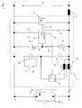
- Fig. 1 shows a circuit arrangement according to the invention, which is designed here as Zündscensan himself 1.
- the high-pressure gas discharge lamp 3 is connected, via which a lamp operating voltage U L drops during operation, the lamp current is indicated by I L.
- the ignition circuit 1 is connected via a designed as a throttle 2 magnetic ballast to the mains voltage U N.
- the circuit arrangement comprises a triggering circuit, which in the in Fig. 1 shown Embodiment, a surge capacitor 30, the primary-side coil winding 13 of a Zündübertragers 10 and a controllable switch 20 has.
- the series connection of the primary-side coil winding 13 and the switch 20 is connected in parallel to the surge capacitor 30.
- the secondary-side coil winding 11 of the Zündübertragers 10 is disposed in the supply line of the lamp.
- the surge capacitor 30 is connected in parallel with a capacitor 40 and a resistor 41 in series. This parallel connection serves to charge the surge capacitor 30.
- the circuit arrangement shown comprises a controller 50, which has a timer module as a subassembly.
- the controller 50 actuates the switch S1 for generating a primary-side ignition pulse in the Zündauslösesclien, which is superimposed pulse-transformed on the secondary side of the Zündübertragers the AC power supply to the lamp.
- the switch 20 is e.g. designed as a field effect transistor.
- the circuit arrangement has a series connection, which comprises at least the resistor 61 and the capacitor 60 and which is connected to the electrodes of the lamp 3 and insofar as this is connected in parallel.
- this series connection connected in parallel with the lamp also has the secondary-side coil winding 11.
- the Con-troller 50 is connected via the connecting lines 54, 55 for power supply.
- the control line 51 controls the switch 20 of the Zündauslöseschaltnikes.
- the controller 50 has a sensor line 53 which is at the voltage U C of the capacitor 60. The detected voltage on the line 53 U C is digitized in the controller via an analog-to-digital converter, not shown, so that the voltage at the capacitor 60 is ready for further processing binary coded in the controller 50.
- the timer 50 in the in Fig. 1 illustrated embodiment, a further control line 52, with which a executed as a field effect transistor second switch 70 is driven.
- the switch 70 together with the secondary winding 11 of the Zündübertragers 10 a series circuit which is connected in parallel to the lamp 3, so that the switch 70, the lamp can be short-circuited.
- the second switch can also be designed as a thyristor or triac, for example.
- Fig. 1 illustrated Zündscensan extract invention The functioning of in Fig. 1 illustrated Zündscensan extract invention will be described below.
- the switch S1 After charging the surge capacitor 30 controls the controller 50 at a time at which the mains voltage is above the lamp voltage, the switch S1 briefly to close and then to open again.
- the surge capacitor 30 serving as the input power source for the tripping circuit discharges via the primary-side coil winding 13 of the ignition transformer 10.
- the magnetization of the primary-side coil winding is transformed via the Zündübertragerkern 12 to the secondary-side coil winding 11 and the mains voltage superimposed.
- a secondary-side ignition pulse is thus applied to the lamp 3, so that it can ignite.
- the controller 50 continuously determines the degree of unbalance of the lamp operating voltage.
- the series connection of the secondary-side coil winding 11, the resistor 61 and the capacitor 60, which is connected to the electrodes of the lamp 3 is used.
- the secondary-side coil winding 11 does not interfere with the detection of this DC voltage component, since the former has a negligible DC resistance.
- the capacitor 60 is symmetrically charged or discharged.
- the voltage U C at the capacitor 60 is digitized by the controller 50 by means of an A / D converter, not shown, whose input is connected to the measuring line 53.
- the controller 50 on the capacitor 60 detects a DC voltage component identical to zero.
- the controller 50 measures a non-zero DC voltage component of the voltage U C , which is a measure of the unbalance of the lamp operating voltage and from the controller 50 with a predetermined value is compared. If, during operation of the lamp, this preset value is exceeded, the lamp 3 is switched off in order to avoid consequential damage, which could be caused for example due to excessive temperature development. For this purpose, the controller 50 controls the switch 70 to close via the control line 52.
- the controller 50 re-directs the switch 70 to open. Since the controller 50 has detected that the lamp is faulty, the control line 51 is blocked, so that the switch 20 in the Zündauslösesclien can not be controlled to close and thus not to generate a firing pulse.
- the controller 50 is set to re-initialize after the power is turned off and then turned on again, and then the switch 20 can again be driven to generate a primary-side firing pulse. It is assumed that after disconnecting the controller from the mains, the lamp replaced and after restarting the network, the new lamp can be operated as described.
- the controller 50 includes a timer device having, in the described embodiment, a count device for detecting the number of lamp firings and a counter for detecting the past ignition timing for a firing attempt.
- a timer device having, in the described embodiment, a count device for detecting the number of lamp firings and a counter for detecting the past ignition timing for a firing attempt.
- a count device for detecting the number of lamp firings
- a counter for detecting the past ignition timing for a firing attempt.
- the controller 50 will close a faulty lamp and omit further ignition attempts.
- an unillustrated memory area is provided in the controller 50, in which the permitted number of lamp ignitions or the allowable ignition time for a detonation attempt are stored.
- the allowed number of ignition attempts and / or the allowable ignition time is made in a Zünd bath of the determined measure for the unbalance of the lamp operating voltage. The lower the unbalance of the lamp operating voltage, the higher the number of permitted lamp ignitions or the permitted ignition time. If the measured unbalance of the lamp operating voltage approaches the limit value, the number of permitted ignition attempts or the permitted ignition time is correspondingly reduced in order to damage the magnetic ballast or ignition circuit when the lamp is in "end-of-life" state avoid.
- the circuit arrangement 1 does not comprise the magnetic ballast designed as a choke 2. In another embodiment of the invention, however, it is provided to integrate the ballast and the ignition circuit in a single unit, see Fig. 2 , This shows a second inventively designed circuit arrangement in which the ballast 2 and the ignition circuit are formed as a unit.
- Fig. 2 illustrated embodiment of the circuit arrangement is otherwise very similar to the in Fig. 1 constructed and differs from this otherwise only in the design of Zündauslöseschari.
- Its switch 20 is designed here as a passive, self-controlled switch.
- the in Fig. 1 does not comprise the magnetic ballast designed as a choke 2.
- Fig. 2 This shows a second inventively designed circuit arrangement in which the ballast 2 and the ignition circuit are formed as a unit.
- Fig. 2 illustrated embodiment of the circuit arrangement is otherwise very similar to the in Fig. 1 constructed and differs from this otherwise only in the design of Zündauslöseschari.
- Its switch 20 is designed here as a passive, self
- the 2 illustrated circuit compares the executed as Sidac or triac switch the voltage applied to it with a switch-internal comparator 21 and turns on exceeding a predetermined voltage value, here about 200 volts.
- a primary ignition pulse is triggered by the Discharge of the surge capacitor 30 is generated, the switch 20 opens again when its holding current is exceeded.
- the electrical design of the components is designed in such a way that here too the triggering circuit is set up for generating a plurality of ignition pulses within a network half-cycle.
- FIG. 2 Another difference of in Fig. 2 shown circuit arrangement in comparison to in Fig. 1 shown is that the controller 50 in Fig. 2 the generation of primary ignition pulses can block that can be controlled via the control line 51, a switch 80 for closing, which is arranged parallel to the surge capacitor 30. The trigger circuit is in turn blocked when, as described above, it has been detected that a predetermined amount of unbalance of the lamp operating voltage has been reached.
Description
Die Erfindung betrifft eine Schaltungsanordnung zum Zünden einer Hochdruck-Gasentladungslampe, welche eingangsseitig an ein magnetisches Vorschaltgerät zur Bereitstellung einer Wechselstrom-Versorgung der Lampe angeschlossen ist, nach dem Oberbegriff von Anspruch 1 sowie ein Verfahren zum Betrieb einer Hochdruck-Gasentladungslampe mit einer Zündschaltungsanordnung.The invention relates to a circuit arrangement for igniting a high-pressure gas discharge lamp, which is connected on the input side to a magnetic ballast for providing an AC supply to the lamp, according to the preamble of
Herkömmliche Schaltungsanordnungen zum Zünden einer Hochdruck-Gasentladungslampe sind häufig als Überlagerungszündschaltung ausgebildet. Diese weist einen Zündübertrager auf, welcher primärseitig mit einer Zündauslöseschaltung verbunden ist und sekundärseitig zwischen dem Vorschaltgerät und der Lampe zur Übertragung eines Zündimpulses auf die Lampe angeordnet ist. Die Schaltungsanordnung weist einen Stoßkondensator und ein erstes Schaltermittel auf. Dabei ist eine Reihenschaltung aus zumindest dem ersten Schaltermittel und einer Primärwicklung des Zündübertragers dem Stoßkondensator parallel geschaltet. Wird nun nach dem Aufladen des Stoßkondensators durch das Schließen des ersten Schaltermittels in der Zündauslöseschaltung ein primärseitiger Zündimpuls erzeugt, überträgt der Zünd-übertrager diesen Zündimpuls auf die Versorgungsschaltung der Lampe. Um einen ausreichend hohen sekundärseitigen Zündimpuls zu erhalten, ist das Übertragungsverhältnis des Zündübertragers entsprechend ausgelegt. Sobald die Lampe gezündet hat, wird in der Regel die Schaltungsanordnung zum Zünden der Lampe abgeschaltet.Conventional circuit arrangements for igniting a high-pressure gas discharge lamp are often designed as a superposition ignition circuit. This has an ignition transformer, which is connected on the primary side with a Zündauslöseschaltung and secondary side between the ballast and the lamp for transmitting an ignition pulse is arranged on the lamp. The circuit arrangement has a surge capacitor and a first switch means. In this case, a series connection of at least the first switching means and a primary winding of the ignition transformer is connected in parallel to the surge capacitor. If a primary-side ignition pulse is now generated after the charging of the surge capacitor by the closing of the first switch means in the ignition triggering circuit, the ignition transformer transmits this ignition pulse to the supply circuit of the lamp. In order to obtain a sufficiently high secondary-side ignition pulse, the transmission ratio of the Zündübertragers is designed accordingly. Once the lamp has ignited, usually the circuit arrangement for igniting the lamp is turned off.
Eine derartige gattungsbildende Schaltungsanordnung ist beispielsweise in der deutschen Offenlegungsschrift
Aufgrund der hohen elektrischen und thermischen Belastung, insbesondere an den Elektroden der Hochdruck-Gasentladungslampe weisen letztere eine beschränkte Lebensdauer auf, was am Ende der Nutzung zu Funktionsstörungen führt. Typisch ist beispielsweise ein sogenannter Cycling-Betrieb, bei welchem die Lampen nach einer kurzen Brennzeit löschen, durch die Zündschaltung wieder gestartet werden usw. Ferner, besteht die Problematik, dass aufgrund des Alterungsprozesses insbesondere an den Elektroden der Lampe hohe Verlustleistungen erzeugt werden, die letztlich zu einem Kurzschluss oder auch zu einem Platzen des Glasgefäßes der Lampe führen können. Derartige Effekte können auch dazu führen, dass das Vorschaltgerät durch die Wärmeentwicklung Schaden nimmt und zusammen mit der defekten Lampe ausgetauscht werden muss.Due to the high electrical and thermal load, in particular at the electrodes of the high-pressure gas discharge lamp, the latter have a limited life, which leads to malfunction at the end of use. Typical is, for example, a so-called cycling operation in which the lamps extinguish after a short burning time, are restarted by the ignition circuit, etc. Furthermore, there is the problem that due to the aging process in particular at the electrodes of the lamp high power losses are generated, which ultimately can lead to a short circuit or even to a bursting of the glass vessel of the lamp. Such effects can also lead to the fact that the ballast is damaged by the heat and must be replaced together with the defective lamp.
Auf dem Gebiet bekannt ist die Verwendung eines Thermoschalters in der Versorgungsschaltung der Lampe, welcher bei einer erhöhten Wärmeentwicklung die Wechselstromversorgung der Lampe unterbricht, wenn der zugeordnete Temperatursensor das Übersteigen einer vorgegebenen Temperatur erfasst. Ein solcher Thermoschalter kann beispielsweise als Schmelzsicherung ausgebildet sein, die nach dem Auftreten einer erhöhten Temperatur in der Umgebung des Vorschaltgeräts bzw. der Hochdruckgasentladungslampe anspricht. Die Verwendung eines solchen Thermoschalters ist vergleichsweise unsicher, da ein solcher Temperatursensor den Fehlerfall in der Lampe erst zeitlich verzögert erfassen kann, weil die Verlustwärme über Wärmeleitung erst vom Entstehungsort der elektrischen Verlustleistung zum Sensor übertragen werden muss. Aus diesem Grunde kann es trotz des Vorsehens eines solchen Thermoschalters beim Betrieb einer Hochdruck-Gasentladungslampe sein, dass im Alterungsfall der Lampe eine so starke Hitzeentwicklung verursacht wird, dass die Halterung der Lampe, das Vorschaltgerät und/oder die Zündschaltung geschädigt wird.Known in the art is the use of a thermal switch in the supply circuit of the lamp, which interrupts the AC supply to the lamp when heat buildup occurs when the associated temperature sensor detects exceeding a predetermined temperature. Such a thermal switch can be designed, for example, as a fuse, which responds after the occurrence of an elevated temperature in the vicinity of the ballast or the high-pressure gas discharge lamp. The use of such a thermal switch is relatively uncertain, since such a temperature sensor can detect the fault in the lamp only delayed in time, because the heat loss must be transferred via heat conduction only from the place of origin of electrical power loss to the sensor. For this reason, it may be despite the provision of such a thermal switch during operation of a high-pressure gas discharge lamp that in the case of aging of the lamp such a strong Heat is caused that the holder of the lamp, the ballast and / or the ignition circuit is damaged.
Insofern liegt der Erfindung die Aufgabe zugrunde, die beschriebenen Nachteile von Schaltungsanordnungen des Standes der Technik zumindest teilweise zu vermeiden.In this respect, the object of the invention is to at least partially avoid the described disadvantages of circuit arrangements of the prior art.
Diese Aufgabe wird auf überraschend einfache Weise durch eine Schaltungsanordnung zum Zünden einer Hochdruck-Gasentladungslampe, welche eingangsseitig an ein magnetisches Vorschaltgerät zur Bereitstellung einer Wechselstrom-Versorgung der Lampe angeschlossen ist, mit den Merkmalen von Anspruch 1 gelöst. Danach weist die erfindungsgemäße Schaltungsanordnung einen Zündübertrager auf, welcher beispielsweise als Impulstransformator ausgebildet sein kann, der primärseitig mit einer Zündauslöseschaltung verbunden und sekundärseitig zwischen dem Vorschaltgerät und der Lampe zur Übertragung eines Zündimpulses auf die Lampe angeordnet ist. Die Schaltungsanordnung umfasst ferner einen Stoßkondensator und ein erstes Schalterelement, wobei in der Zündauslöseschaltung eine Reihenschaltung, umfassend zumindest das erste Schalterelement und eine Primärwicklung des Zündübertragers dem Stoßkondensator parallel geschaltet ist. Die erfindungsgemäße Schaltungsanordnung zeichnet sich dadurch aus, dass eine Reihenschaltung, welche zumindest ein steuerbares zweites Schaltermittel aufweist, der Lampe zum Löschen derselben parallel geschaltet ist und ein Mittel zur Erfassung des Maßes der Unsymmetrie der Lampenspannung vorgesehen ist sowie eine Steuereinrichtung zum Löschen der Lampe durch das Ansteuern des zweiten Schaltermittels im Ansprechen auf die erfasste Unsymmetrie der Lampenbetriebsspannung.This object is achieved in a surprisingly simple manner by a circuit arrangement for igniting a high-pressure gas discharge lamp, which is connected on the input side to a magnetic ballast for providing an AC supply to the lamp, with the features of
Dadurch, dass die erfindungsgemäße Schaltungsanordnung zur Ermittlung des Grades der Unsymmetrie der Lampenbetriebsspannung ausgebildet ist, kann der Alterungszustand der Gasentladungslampe ermittelt werden, bevor Funktionsstörungen oder Schädigungen am Vorschaltgerät oder an der Schaltungsanordnung auftreten. Diese Wirkung beruht darauf, dass eine solche Alterung einer Hochdruck-Gasentladungslampe in der Regel auf eine Unsymmetrie der Kathodenfallspannung an den beiden Elektroden zurückgeht, welche wiederum durch einen Unterschied in der Austrittsarbeit der Elektronen an den beiden Elektroden verursacht wird.The fact that the circuit arrangement according to the invention is designed to determine the degree of asymmetry of the lamp operating voltage, the Aging condition of the gas discharge lamp can be determined before malfunction or damage to the ballast or the circuit arrangement occur. This effect is due to the fact that such aging of a high-pressure gas discharge lamp as a rule is due to an asymmetry of the cathode drop voltage at the two electrodes, which in turn is caused by a difference in the work function of the electrons at the two electrodes.
Übersteigt die Unsymmetrie der Lampenbetriebsspannung einen vorgegebenen Wert, kann mit dem steuerbaren zweiten Schaltermittel die Lampe kurzgeschlossen und somit gelöscht werden, wodurch verhindert wird, dass sich der Grad der Unsymmetrie der Lampenbetriebsspannung weiter erhöht. Hierdurch wird die Entstehung einer gefährlichen Verlustleistung beim Betrieb der Lampe vermieden, da ansonsten durch die Asymmetrie der Kathodenfallspannung an den Elektroden trotz der Wechselstromversorgung ein Gleichrichtungseffekt in der Lampe hervorgerufen wird, bei welchem das magnetische Vorschaltgerät, insbesondere eine Drossel, keine strombegrenzende Wirkung besitzt. Das von der Steuereinrichtung zum Kurzschließen der Lampe ansteuerbare zweite Schaltermittel ist dabei Teil einer Reihenschaltung, welche der Lampe parallel geschaltet ist und zumindest dieses Schaltermittel und die Anschlüsse zur Lampe aufweist.If the unbalance of the lamp operating voltage exceeds a predetermined value, the controllable second switch means can short the lamp and thus erase it, thereby preventing the degree of unbalance of the lamp operating voltage from being further increased. In this way, the emergence of a dangerous power loss during operation of the lamp is avoided, since otherwise caused by the asymmetry of the cathode drop voltage at the electrodes despite the AC power rectification effect in the lamp, in which the magnetic ballast, in particular a choke, has no current-limiting effect. The controllable by the controller for shorting the lamp second switch means is part of a series circuit, which is connected in parallel to the lamp and at least this switch means and the connections to the lamp.
Im Gegensatz zu herkömmlichen Schaltungsanordnungen ist demnach die erfindungsgemäße Schaltungsanordnung in der Lage, den Betrieb der Hochdruck-Gasentladungslampe früh genug zu beenden, bevor andere Bauteile beim Weiterbetrieb der Lampe beschädigt werden oder andere Funktionsstörungen auftreten können. In der Regel reicht es dann aus, die gealterte Hochdruck-Gasentladungslampe auszuwechseln, um die betreffende Leuchteinrichtung wieder zu betreiben.In contrast to conventional circuit arrangements, the circuit arrangement according to the invention is accordingly able to terminate the operation of the high-pressure gas discharge lamp early enough before other components can be damaged during further operation of the lamp or other malfunctions can occur. In general, then it is sufficient to replace the aged high-pressure gas discharge lamp to operate the relevant lighting device again.
Es kann zweckmäßig sein, wenn die Steuervorrichtung der erfindungsgemäßen Schaltungsanordnung eine Timerschaltung aufweist zur Steuerung des Zündbetriebs der Schaltungsanordnung, insbesondere mit einer Zählvorrichtung zur Erfassung der Anzahl von Lampenzündungen und/oder einer Zählvorrichtung zur Erfassung der vergangenen Zündzeit für einen Zündversuch. Insofern kann die Gesamtzündzeit eines Zündversuchs erfasst und mit einem gespeicherten Wert verglichen werden. Beim Überschreiten dieses vorgegebenen Wertes kann auf eine Fehlfunktion der Lampe geschlossen und insofern weitere Zündversuche unterbunden werden. Gleiches gilt für das Überschreiten einer vorgegebenen Anzahl von Lampenzündungen innerhalb des Zündbetriebs der Schaltungsanordnung.It may be expedient if the control device of the circuit arrangement according to the invention has a timer circuit for controlling the ignition operation of the circuit arrangement, in particular with a counting device for detecting the number of lamp ignitions and / or a counting device for detecting the past ignition time for a detonation attempt. In this respect, the total ignition time of a Zündversuchs can be detected and compared with a stored value. If this predetermined value is exceeded, it is possible to conclude that the lamp has malfunctioned and, to that extent, to prevent further ignition attempts. The same applies to the exceeding of a predetermined number of lamp ignitions within the ignition operation of the circuit arrangement.
Darüber hinaus kann es auch zweckmäßig sein, zum Abschalten und/oder Blockieren der Zündauslöseschaltung einen steuerbaren, dritten Schalter vorzusehen, der beispielsweise dem Stoßkondensator parallel geschaltet ist und insofern diesen bei Bedarf kurzschließt.In addition, it may also be expedient to provide a controllable, third switch for switching off and / or blocking the Zündauslöseschaltung, which is connected in parallel, for example, the surge capacitor and insofar short-circuits if necessary.
Um den Grad der Unsymmetrie der Lampenbetriebsspannung zu erfassen, kann eine Reihenschaltung vorgesehen sein, welche zumindest einen Kondensator und einen Widerstand aufweist, wobei diese Reihenschaltung der Lampe parallel geschaltet ist. Durch diese Maßnahme wird erreicht, dass sich der Gleichspannungsanteil der Lampenbetriebsspannung in der Spannung dieses Kondensators widerspiegelt, welche durch ein entsprechendes Erfassungsmittel bestimmbar ist. Beispielsweise kann hierzu die Steuereinrichtung einen Analog-Digital-Wandler aufweisen, mit welchem die angegebene Kondensatorspannung zur weiteren Verarbeitung digitalisierbar ist.In order to detect the degree of asymmetry of the lamp operating voltage, a series circuit may be provided which has at least one capacitor and one resistor, wherein this series connection of the lamp is connected in parallel. By this measure it is achieved that the DC voltage component of the lamp operating voltage is reflected in the voltage of this capacitor, which can be determined by a corresponding detection means. For example, for this purpose, the control device having an analog-to-digital converter, with which the indicated capacitor voltage can be digitized for further processing.
Es kann zweckmäßig sein, wenn das magnetische Vorschaltgerät als herkömmliche Drossel ausgebildet ist. Darüber hinaus kann es zweckmäßig sein, wenn die das zweite Schaltermittel aufweisende Reihenschaltung diese Drossel nicht umfasst, sodass die Drossel durch den mit dem zweiten Schaltermittel verursachten Kurzschluss zum Löschen der Lampe nicht belastet wird.It may be expedient if the magnetic ballast is designed as a conventional throttle. In addition, can it may be expedient if the series circuit comprising the second switch means does not comprise this throttle, so that the choke is not loaded by the short circuit caused by the second switch means for extinguishing the lamp.
Verfahrensseitig wird die obige Aufgabe gelöst durch ein Verfahren zum Betrieb einer Hochdruck-Gasentladungslampe, die an ein magnetisches Vorschaltgerät zur Bereitstellung einer Wechselstrom-Versorgungsspannung angeschlossen ist, mit einer Zündschaltungsanordnung, die nach dem Zünden der Lampe abgeschaltet wird. Das erfindungsgemäße Verfahren zeichnet sich dadurch aus, dass während des Betriebs der Lampe der Grad der Unsymmetrie der Lampenbetriebsspannung erfasst wird und dieser Grad mit einem vorbestimmten Wert verglichen wird und beim Überschreiten des vorbestimmten Wertes die Lampe zum Löschen der Lampenentladung kurzgeschlossen wird.The method, the above object is achieved by a method for operating a high-pressure gas discharge lamp, which is connected to a magnetic ballast for providing an AC supply voltage, with an ignition circuit, which is switched off after the ignition of the lamp. The inventive method is characterized in that during operation of the lamp, the degree of asymmetry of the lamp operating voltage is detected and this degree is compared with a predetermined value and when exceeding the predetermined value, the lamp is shorted to extinguish the lamp discharge.
Hierdurch wird die Entstehung einer hohen Verlustwärme beim Betrieb der Lampe vermieden, wodurch letztlich eine Funktionsstörung bzw. eine Schädigung des Vorschaltgeräts und/oder der Schaltungsanordnung verhindert werden kann.As a result, the emergence of a high heat loss during operation of the lamp is avoided, which ultimately a malfunction or damage to the ballast and / or the circuit arrangement can be prevented.
Es kann zweckmäßig sein, wenn die Lampe über ein vorbestimmtes Zeitintervall kurzgeschlossen und nach Ablauf dieses Zeitintervalls der Kurzschluss wieder aufgehoben wird. Dieses Zeitintervall kann beispielsweise einige wenige Millisekunden umfassen, die ausreichen, um die Hochdruck-Gasentladungslampe zu löschen. Danach kann der Kurzschluss wieder aufgehoben werden, soweit sichergestellt ist, dass die Lampe nicht mehr gezündet wird oder nachfolgende Zündversuche weiter erlaubt sind.It may be expedient if the lamp is short-circuited over a predetermined time interval and the short-circuit is canceled again after the expiration of this time interval. This time interval may, for example, comprise a few milliseconds sufficient to extinguish the high pressure gas discharge lamp. Thereafter, the short circuit can be canceled again, as far as it is ensured that the lamp is not ignited or subsequent ignition attempts are allowed.
Um zu vermeiden, dass insbesondere bei einem selbst gesteuerten ersten Schalter wie einem Sidac nach der Erfassung des Überschreitens eines vorbestimmten Grades der Unsymmetrie der Lampenbetriebsspannung kein primärseitiger Zündimpuls in der Zündauslöseschaltung erzeugt wird, kann erfindungsgemäß vorgesehen sein, dass gleichzeitig mit oder nach dem Kurzschließen der Lampe die Zündschaltungsanordnung blockiert wird, z.B. durch das Kurzschließen des Stoßkondensators.In order to avoid that in particular with a self-controlled first switch such as a Sidac after the detection of the Beyond a predetermined degree of asymmetry of the lamp operating voltage no primary-side ignition pulse is generated in the Zündauslöseschaltung, can be provided according to the invention that simultaneously with or after the short-circuiting of the lamp, the ignition circuit is blocked, for example by shorting the surge capacitor.
Um sicherzustellen, dass nach dem Austausch einer gealterten Hochdruck-Gasentladungslampe die neue Lampe mit der Schaltungsanordnung betrieben werden kann, wird vorzugsweise die Blockade der Zündschaltungsanordnung aufgehoben, nachdem diese von der Stromversorgung getrennt und nachfolgend wieder an diese angeschlossen wird.To ensure that after replacement of an aged high-pressure gas discharge lamp, the new lamp can be operated with the circuit arrangement, the blockage of the ignition circuit is preferably removed after it is disconnected from the power supply and subsequently reconnected to this.
Die Erfassung des Grades der Unsymmetrie der Lampenspannung während des Betriebs der Lampe kann auch genutzt werden, um den zeitlichen Verlauf dieser Unsymmetrie zu ermitteln, wodurch letztlich eine Prognose für die noch verbleibende Betriebszeit der Lampe ermittelbar ist. Beispielsweise kann vorgesehen sein, dass aus dem Verlauf der Unsymmetrie der Lampenbetriebsspannung über ein vorgegebenes Zeitintervall, beispielsweise durch lineare Interpolation die Zeitdauer ermittelt wird, die verbleibt, bis die Lampe einen vorbestimmten Grenzwert der Unsymmetrie der Lampenbetriebsspannung erreicht, an dem die Lampe erfindungsgemäß ausgeschaltet wird. Diese ermittelte Zeitdauer kann optisch angezeigt oder auch digital bzw. analog an einem entsprechenden Port zur weiteren Verarbeitung bzw. Anzeige ausgegeben werden.The detection of the degree of asymmetry of the lamp voltage during operation of the lamp can also be used to determine the time course of this asymmetry, whereby ultimately a prognosis for the remaining operating time of the lamp can be determined. For example, it can be provided that from the course of the unbalance of the lamp operating voltage over a predetermined time interval, for example by linear interpolation, the time duration is determined, which remains until the lamp reaches a predetermined limit of the unbalance of the lamp operating voltage at which the lamp is turned off according to the invention. This determined period of time can be optically displayed or digitally or analogue output at a corresponding port for further processing or display.
Ferner kann es zweckmäßig sein, das erfasste Maß der Unsymmetrie der Lampenbetriebsspannung während des Betriebs zur Festlegung einer erlaubten Anzahl von Zündversuchen zu verwenden. Nach Ablauf dieser in Abhängigkeit des erfassten Grades der Unsymmetrie der Lampenbetriebsspannung festgelegten Anzahl der Zündversuche kann dann die Zündschaltungsanordnung blockiert werden. In gleicher Weise kann erfindungsgemäß vorgesehen sein, dass der ermittelte Grad der Unsymmetrie der Lampenbetriebsspannung zur Festlegung der erlaubten Zündzeit verwendet wird, innerhalb dessen Zündversuche durchgeführt werden dürfen. Beispielsweise kann die erlaubte Anzahl der Zündversuche bzw. die erlaubte Zündzeit proportional zum Abstand der erfassten Unsymmetrie von der erlaubten Unsymmetrie der Lampenbetriebsspannung berechnet werden. Dabei entspricht diese erlaubte Unsymmetrie der Lampenbetriebsspannung gerade einem dem Grad, kurz bevor die Lampe gelöscht wird.Furthermore, it may be expedient to use the detected measure of the unbalance of the lamp operating voltage during operation to establish an allowable number of ignition attempts. After expiration of this determined in dependence on the detected degree of asymmetry of the lamp operating voltage number of ignition attempts can then the ignition circuit be blocked. In the same way, it can be provided according to the invention that the determined degree of asymmetry of the lamp operating voltage is used for determining the permitted ignition time within which ignition attempts may be carried out. For example, the permitted number of ignition attempts or the permitted ignition time can be calculated in proportion to the distance of the detected asymmetry from the permitted asymmetry of the lamp operating voltage. In this case, this allowed unbalance of the lamp operating voltage just corresponds to the degree just before the lamp is extinguished.
Die Erfindung wird im Folgenden durch das Beschreiben einiger Ausführungsformen unter Bezugnahme auf die beiliegenden Zeichnungen erläutert, wobei
- Fig. 1
- eine erste Ausführungsform einer erfindungsgemäßen Schaltungsanordnung zum Zünden einer Hochdruck-Gasentladungslampe in einer Prinzipskizze und
- Fig. 2
- eine zweite Ausführungsform einer erfindungsgemäßen Schaltungsanordnung zum Zünden einer Hochdruck-Gasentladungslampe in einer Prinzipskizze
- Fig. 1
- a first embodiment of a circuit arrangement according to the invention for igniting a high pressure gas discharge lamp in a schematic diagram and
- Fig. 2
- A second embodiment of a circuit arrangement according to the invention for igniting a high pressure gas discharge lamp in a schematic diagram
Die gezeigte Schaltungsanordnung umfasst einen Controller 50, welcher als Unterbaugruppe einen Timerbaustein aufweist. Der Controller 50 steuert den Schalter S1 zur Erzeugung eines primärseitigen Zündimpulses in der Zündauslöseschaltung an, welcher impulstransformiert auf der Sekundärseite des Zündübertragers der Wechselstromversorgung der Lampe überlagert wird. Der Schalter 20 ist z.B. als Feldeffekttransistor ausgebildet.The circuit arrangement shown comprises a
Ferner weist die Schaltungsanordnung eine Reihenschaltung auf, welche zumindest den Widerstand 61 und den Kondensator 60 umfasst und die an die Elektroden der Lampe 3 angeschlossen und insofern dieser parallel geschaltet ist. In dem gezeigten Beispiel weist diese der Lampe parallel geschaltete Reihenschaltung auch die sekundärseitige Spulenwicklung 11 auf. Der Con-troller 50 ist über die Anschlussleitungen 54, 55 zur Energieversorgung angeschlossen. Die Steuerleitung 51 steuert den Schalter 20 des Zündauslöseschaltkreises. Ferner weist der Controller 50 eine Sensorleitung 53 auf, welche auf der Spannung UC des Kondensators 60 liegt. Die über die Leitung 53 erfasste Spannung UC wird im Controller über einen nicht dargestellten Analog-Digital-Wandler digitalisiert, sodass die Spannung am Kondensator 60 zur weiteren Verarbeitung binär codiert im Controller 50 bereitsteht.Furthermore, the circuit arrangement has a series connection, which comprises at least the
Darüber hinaus weist der Timer 50 in der in
Die Funktionsweise der in
Während des Betriebs der Lampe 3 ermittelt der Controller 50 kontinuierlich das Maß der Unsymmetrie der Lampenbetriebsspannung. Hierzu dient die Reihenschaltung der sekundärseitigen Spulenwicklung 11, des Widerstands 61 und des Kondensators 60, welche an die Elektroden der Lampe 3 angeschlossen ist. Dabei stört die sekundärseitige Spulenwicklung 11 die Erfassung dieses Gleichsspannungsanteils nicht, da erstere einen vernachlässigbaren Gleichspannungswiderstand aufweist.During operation of the
Wenn die Lampenbetriebsspannung in beiden Netzhalbwellen symmetrisch zueinander verläuft, wird der Kondensator 60 symmetrisch aufgeladen bzw. entladen. Wie schon erwähnt, wird die Spannung UC am Kondensator 60 vom Controller 50 mittels eines nicht dargestellten A/D-Wandlers digitalisiert, dessen Eingang mit der Messleitung 53 verbunden ist. Beim Vorliegen einer symmetrischen Lampenbetriebsspannung in beiden Halbwellen erfasst der Controller 50 am Kondensator 60 einen Gleichspannungsanteil identisch Null.If the lamp operating voltage is symmetrical to each other in both mains half-waves, the
Wie beschrieben, sind Hochdruck-Gasentladungslampen einem Verschleiß unterworfen, der letztlich zum Ausfall der Lampe führt. In der Regel zeigt sich dieser Alterungsprozess in einer unterschiedlichen Kathodenfallspannung an beiden Elektroden der Lampe, was eine Gleichrichterwirkung der Lampe zur Folge hat. In diesem Fall misst der Controller 50 einen von Null verschiedenen Gleichspannungsanteil der Spannung UC, welcher ein Maß für die Unsymmetrie der Lampenbetriebsspannung darstellt und vom Controller 50 mit einem vorgegebenen Wert verglichen wird. Sollte im Betrieb der Lampe dieser voreingestellte Wert überschritten werden, wird die Lampe 3 zur Vermeidung von Folgeschäden, die beispielsweise aufgrund einer zu hohen Temperaturentwicklung verursacht werden könnten, abgeschaltet. Hierzu steuert der Controller 50 über die Steuerleitung 52 den Schalter 70 zum Schließen an. Hierdurch wird die Lampe 3 von der Versorgungsspannung getrennt, wodurch die Lampe erlischt. Nach einem beispielhaften Zeitintervall von 10 Millisekunden steuert der Controller 50 den Schalter 70 wieder zum Öffnen an. Da der Controller 50 erkannt hat, dass die Lampe fehlerhaft ist, wird die Steuerleitung 51 blockiert, sodass der Schalter 20 in der Zündauslöseschaltung nicht mehr zum Schließen und damit nicht zum Erzeugen eines Zündimpulses angesteuert werden kann. Der Controller 50 ist so eingestellt, dass dieser nach dem Abschalten der Stromversorgung und dem Wiederanschalten neu initialisiert wird und dann der Schalter 20 wieder zum Erzeugen eines primärseitigen Zündimpulses angesteuert werden kann. Dabei wird davon ausgegangen, dass nach dem Trennen des Controllers vom Netz die Lampe ausgewechselt und nach dem Wiedereinschalten des Netzes die neue Lampe wie beschrieben betrieben werden kann.As described, high-pressure gas discharge lamps are subject to wear, which ultimately leads to failure of the lamp. In general, this aging process manifests itself in a different cathode drop voltage on both electrodes of the lamp, resulting in a rectifier effect of the lamp. In this case, the
Wie in
In der in
Ein weiterer Unterschied der in
- 11
- Schaltungsanordnungcircuitry
- 22
- Drosselthrottle
- 33
- Hochdruck-GasentladungslampeHigh-pressure gas discharge lamp
- 1010
- Zündübertrager (Impulstransformator)Ignition transformer (pulse transformer)
- 1111
- Sekundärseitige Spulenwicklung/SpuleSecondary coil winding / coil
- 1212
- ZündübertragerkernZündübertragerkern
- 1313
- Primärseitige Spulenwicklung/SpulePrimary coil winding / coil
- 2020
- Schalterswitch
- 3030
- Stoßkondensatorpulse capacitor
- 4040
- Kondensatorcapacitor
- 4141
- Widerstandresistance
- 5050
- Controllercontroller
- 51, 5251, 52
- Steuerleitungcontrol line
- 5353
- MessleitungMeasurement line
- 54, 5554, 55
- SpannungsversorgungleitungPower Line
- 6060
- Kondensatorcapacitor
- 6161
- Widerstandresistance
- 7070
- Schalterswitch
- 8080
- Schalterswitch
Claims (12)
- Switching assembly for igniting a high-pressure gas discharge lamp which is connected on the input side thereof to a magnetic ballast for providing an alternating current supply of the lamp, the switching assembly comprising:- an ignition transformer which is connected on the primary side thereof to an ignition trigger circuit and which is disposed on the secondary side thereof between the ballast and the lamp, for transmitting an ignition pulse to the lamp,- a surge capacitor and a first switch means, wherein in said ignition trigger circuit a series connection comprising at least said first switch means and a primary winding of the ignition transformer are connected in parallel with said surge capacitor;characterized in that a series connection (70, 11) including a controllable second switch means (70) is connected in parallel with said lamp (3) for extinguishing the lamp and that a means for detecting the level of an unbalance of the lamp operating voltage is provided as well as a control device (50) for extinguishing the lamp by controlling the second switch means in response to said detected unbalance of the lamp operating voltage.
- Switching arrangement according to claim 1, characterized in that the control device (50) includes a timer circuit for controlling the ignition operation of the switching arrangement (1), with a counting device for detecting the number of lamp ignitions and/or a counting device for detecting the ignition time that has passed for an ignition attempt.
- Switching arrangement according to claim 1 or 2, characterized in that a series connection (60, 61, 11) comprising at least one capacitor (60) and a resistor (61) is connected in parallel with the lamp and that there is further provided a means for detecting the voltage at the capacitor.
- Switching arrangement according to claim 1, 2 or 3, characterized in that the magnetic ballast is configured as an inductor (2) and that the series connection including the second switch means (70) and connected in parallel with the lamp (3) does not include said inductor.
- Switching arrangement according to one of the claims 2 to 4, as far as referred back to claim 2, characterized in that third switch means (80) are connected in parallel with the surge capacitor (3).
- Method for operating a high-pressure gas discharge lamp that is connected to a magnetic ballast for providing an alternating current supply, with an ignition circuit arrangement that is deactivated after the ignition of the lamp, characterized in that during the operation of the lamp (3) a level for the unbalance of the lamp operating voltage is detected, that this detected level for the unbalance is compared to a predetermined value and that the lamp is short-circuited for extinguishing the lamp discharge when said predetermined value is exceeded.
- Method according to claim 6, characterized in that the lamp (3) is short-circuited for a predetermined time interval and that said short-circuit is cancelled after the expiration of this predetermined time interval.
- Method according to claim 6 or 7, characterized in that the lamp ignition ciruit arrangement is blocked simultaneously with or after short-circuiting the lamp (3).
- Method according to claim 8, characterized in that blocked state of the ignition circuit arrangement is cancelled after the ignition circuit arrangement is separated from the power supply and the ignition circuit arrangement is reconnected to the power supply.
- Method according to one of the claims 6 to 9, characterized in that a detected level for the unbalance of the lamp operating voltage is memorized.
- Method according to one of the claims 6 to 10, characterized in that during the ignition of the lamp, a detected level for the unbalance of the lamp operating voltage for fixing an allowable number of ignition attempts is considered before the ignition circuit arrangement is blocked.
- Method according to one of the claims 6 to 11, characterized in that during the ignition of the lamp, a detected level for the unbalance of the lamp operating voltage for fixing an allowable ignition time is considered before the ignition circuit arrangement is blocked.
Applications Claiming Priority (1)
| Application Number | Priority Date | Filing Date | Title |
|---|---|---|---|
| DE200610016827 DE102006016827A1 (en) | 2006-04-07 | 2006-04-07 | Circuit arrangement for high-pressure gas discharge lamps |
Publications (3)
| Publication Number | Publication Date |
|---|---|
| EP1843645A2 EP1843645A2 (en) | 2007-10-10 |
| EP1843645A3 EP1843645A3 (en) | 2008-07-02 |
| EP1843645B1 true EP1843645B1 (en) | 2015-03-25 |
Family
ID=38229302
Family Applications (1)
| Application Number | Title | Priority Date | Filing Date |
|---|---|---|---|
| EP20070007165 Not-in-force EP1843645B1 (en) | 2006-04-07 | 2007-04-05 | Switching assembly for high pressure gas discharge lamps |
Country Status (2)
| Country | Link |
|---|---|
| EP (1) | EP1843645B1 (en) |
| DE (1) | DE102006016827A1 (en) |
Families Citing this family (4)
| Publication number | Priority date | Publication date | Assignee | Title |
|---|---|---|---|---|
| DE102010039487A1 (en) * | 2010-08-18 | 2012-02-23 | Osram Ag | Circuit arrangement and method for operating a gas discharge lamp |
| DE102010042776A1 (en) * | 2010-10-21 | 2012-04-26 | Bag Engineering Gmbh | Circuit arrangement for igniting and supplying power to e.g. high-pressure lamp, has load path provided at output side for connecting device parallel to lamp and comprising controllable switch unit |
| DE102010043081A1 (en) * | 2010-10-28 | 2012-05-03 | Bag Engineering Gmbh | Ignition circuit arrangement for igniting a discharge lamp, such as a high-pressure lamp |
| AT12721U1 (en) * | 2011-04-22 | 2012-10-15 | Tridonic Gmbh & Co Kg | DEVICE FOR OPERATING A HIGH-PRESSURE DISCHARGE LAMP |
Family Cites Families (4)
| Publication number | Priority date | Publication date | Assignee | Title |
|---|---|---|---|---|
| US4207500A (en) * | 1978-12-14 | 1980-06-10 | Area Lighting Research, Inc. | Cut-off arrangement for and method of protecting a ballast-starter circuit from high pressure sodium lamp cycling malfunction |
| DE19531623B4 (en) * | 1995-08-28 | 2010-09-23 | Tridonicatco Gmbh & Co. Kg | Method and circuit arrangement for igniting a high-pressure gas discharge lamp |
| DE19531622B4 (en) * | 1995-08-28 | 2011-01-13 | Tridonicatco Gmbh & Co. Kg | Ignition circuit for a high pressure gas discharge lamp |
| DE102004045834A1 (en) * | 2004-09-22 | 2006-03-23 | Bag Electronics Gmbh | ignitor |
-
2006
- 2006-04-07 DE DE200610016827 patent/DE102006016827A1/en not_active Withdrawn
-
2007
- 2007-04-05 EP EP20070007165 patent/EP1843645B1/en not_active Not-in-force
Also Published As
| Publication number | Publication date |
|---|---|
| EP1843645A2 (en) | 2007-10-10 |
| DE102006016827A1 (en) | 2007-10-11 |
| EP1843645A3 (en) | 2008-07-02 |
Similar Documents
| Publication | Publication Date | Title |
|---|---|---|
| EP1519638B1 (en) | Method for operating a low pressure discharge lamp | |
| DE4129557C2 (en) | Power supply circuit for a gas discharge lamp in a vehicle | |
| DE4412518C2 (en) | Circuit arrangement for igniting and operating a high-pressure discharge lamp | |
| EP0677981B1 (en) | Ballast for discharge lamps with lamp change detecting means | |
| EP0515977B1 (en) | Electronic ballast for high pressure discharge lamps used in automotive applications | |
| EP2377372B1 (en) | Method, device and lighting system | |
| EP1103166B1 (en) | Electronic ballast for at least one low-pressure discharge lamp | |
| EP1843645B1 (en) | Switching assembly for high pressure gas discharge lamps | |
| DE19531622B4 (en) | Ignition circuit for a high pressure gas discharge lamp | |
| EP1901591B1 (en) | Ignition of gas discharge lamps in variable ambient conditions | |
| DE19531623B4 (en) | Method and circuit arrangement for igniting a high-pressure gas discharge lamp | |
| EP0615267A1 (en) | Circuit for testing switch- or relay contacts | |
| EP2047720A1 (en) | Apparatus and method for monitoring at least one fluorescent lamp | |
| EP1424881A1 (en) | Method and device for driving a fluorescent lamp | |
| EP1992203B1 (en) | Electronic ballast and method for operating an electrical lamp | |
| EP2011373B1 (en) | Superimposed-type ignition device for high-pressure discharge lamps | |
| EP2796012B1 (en) | Method, operating device and lighting system with integrated lamp rectifier effect detection | |
| EP0759684A1 (en) | Starting device for a high pressure discharge lamp | |
| DE3723278C2 (en) | ||
| DE1913715A1 (en) | Control device for a furnace | |
| EP2208401B1 (en) | Electronic ballast and method for operating at least one first and second discharge lamp | |
| DE102005058222A1 (en) | Method for fault detection when operating high-pressure discharge lamps on electronic ballasts | |
| DE2809994C3 (en) | Electronic safety timer for gas or oil burners | |
| DE19819671B4 (en) | Circuit arrangement for the protection of fluorescent lamps and electronic ballast | |
| DE202005003632U1 (en) | Ignition circuit arrangement with increased reliability |
Legal Events
| Date | Code | Title | Description |
|---|---|---|---|
| PUAI | Public reference made under article 153(3) epc to a published international application that has entered the european phase |
Free format text: ORIGINAL CODE: 0009012 |
|
| AK | Designated contracting states |
Kind code of ref document: A2 Designated state(s): AT BE BG CH CY CZ DE DK EE ES FI FR GB GR HU IE IS IT LI LT LU LV MC MT NL PL PT RO SE SI SK TR |
|
| AX | Request for extension of the european patent |
Extension state: AL BA HR MK YU |
|
| PUAL | Search report despatched |
Free format text: ORIGINAL CODE: 0009013 |
|
| AK | Designated contracting states |
Kind code of ref document: A3 Designated state(s): AT BE BG CH CY CZ DE DK EE ES FI FR GB GR HU IE IS IT LI LT LU LV MC MT NL PL PT RO SE SI SK TR |
|
| AX | Request for extension of the european patent |
Extension state: AL BA HR MK RS |
|
| RIC1 | Information provided on ipc code assigned before grant |
Ipc: H05B 41/04 20060101ALI20080528BHEP Ipc: H05B 41/288 20060101AFI20070718BHEP |
|
| 17P | Request for examination filed |
Effective date: 20080806 |
|
| 17Q | First examination report despatched |
Effective date: 20080912 |
|
| AKX | Designation fees paid |
Designated state(s): AT BE BG CH CY CZ DE DK EE ES FI FR GB GR HU IE IS IT LI LT LU LV MC MT NL PL PT RO SE SI SK TR |
|
| GRAP | Despatch of communication of intention to grant a patent |
Free format text: ORIGINAL CODE: EPIDOSNIGR1 |
|
| INTG | Intention to grant announced |
Effective date: 20141010 |
|
| GRAS | Grant fee paid |
Free format text: ORIGINAL CODE: EPIDOSNIGR3 |
|
| GRAA | (expected) grant |
Free format text: ORIGINAL CODE: 0009210 |
|
| AK | Designated contracting states |
Kind code of ref document: B1 Designated state(s): AT BE BG CH CY CZ DE DK EE ES FI FR GB GR HU IE IS IT LI LT LU LV MC MT NL PL PT RO SE SI SK TR |
|
| REG | Reference to a national code |
Ref country code: GB Ref legal event code: FG4D Free format text: NOT ENGLISH |
|
| REG | Reference to a national code |
Ref country code: CH Ref legal event code: EP |
|
| REG | Reference to a national code |
Ref country code: IE Ref legal event code: FG4D Free format text: LANGUAGE OF EP DOCUMENT: GERMAN |
|
| REG | Reference to a national code |
Ref country code: DE Ref legal event code: R096 Ref document number: 502007013813 Country of ref document: DE Effective date: 20150507 |
|
| REG | Reference to a national code |
Ref country code: AT Ref legal event code: REF Ref document number: 718519 Country of ref document: AT Kind code of ref document: T Effective date: 20150515 |
|
| PG25 | Lapsed in a contracting state [announced via postgrant information from national office to epo] |
Ref country code: SE Free format text: LAPSE BECAUSE OF FAILURE TO SUBMIT A TRANSLATION OF THE DESCRIPTION OR TO PAY THE FEE WITHIN THE PRESCRIBED TIME-LIMIT Effective date: 20150325 Ref country code: LT Free format text: LAPSE BECAUSE OF FAILURE TO SUBMIT A TRANSLATION OF THE DESCRIPTION OR TO PAY THE FEE WITHIN THE PRESCRIBED TIME-LIMIT Effective date: 20150325 Ref country code: FI Free format text: LAPSE BECAUSE OF FAILURE TO SUBMIT A TRANSLATION OF THE DESCRIPTION OR TO PAY THE FEE WITHIN THE PRESCRIBED TIME-LIMIT Effective date: 20150325 |
|
| REG | Reference to a national code |
Ref country code: LT Ref legal event code: MG4D |
|
| PG25 | Lapsed in a contracting state [announced via postgrant information from national office to epo] |
Ref country code: GR Free format text: LAPSE BECAUSE OF FAILURE TO SUBMIT A TRANSLATION OF THE DESCRIPTION OR TO PAY THE FEE WITHIN THE PRESCRIBED TIME-LIMIT Effective date: 20150626 Ref country code: LV Free format text: LAPSE BECAUSE OF FAILURE TO SUBMIT A TRANSLATION OF THE DESCRIPTION OR TO PAY THE FEE WITHIN THE PRESCRIBED TIME-LIMIT Effective date: 20150325 |
|
| PG25 | Lapsed in a contracting state [announced via postgrant information from national office to epo] |
Ref country code: NL Free format text: LAPSE BECAUSE OF FAILURE TO SUBMIT A TRANSLATION OF THE DESCRIPTION OR TO PAY THE FEE WITHIN THE PRESCRIBED TIME-LIMIT Effective date: 20150325 |
|
| PG25 | Lapsed in a contracting state [announced via postgrant information from national office to epo] |
Ref country code: CZ Free format text: LAPSE BECAUSE OF FAILURE TO SUBMIT A TRANSLATION OF THE DESCRIPTION OR TO PAY THE FEE WITHIN THE PRESCRIBED TIME-LIMIT Effective date: 20150325 Ref country code: ES Free format text: LAPSE BECAUSE OF FAILURE TO SUBMIT A TRANSLATION OF THE DESCRIPTION OR TO PAY THE FEE WITHIN THE PRESCRIBED TIME-LIMIT Effective date: 20150325 Ref country code: RO Free format text: LAPSE BECAUSE OF FAILURE TO SUBMIT A TRANSLATION OF THE DESCRIPTION OR TO PAY THE FEE WITHIN THE PRESCRIBED TIME-LIMIT Effective date: 20150325 Ref country code: EE Free format text: LAPSE BECAUSE OF FAILURE TO SUBMIT A TRANSLATION OF THE DESCRIPTION OR TO PAY THE FEE WITHIN THE PRESCRIBED TIME-LIMIT Effective date: 20150325 Ref country code: PT Free format text: LAPSE BECAUSE OF FAILURE TO SUBMIT A TRANSLATION OF THE DESCRIPTION OR TO PAY THE FEE WITHIN THE PRESCRIBED TIME-LIMIT Effective date: 20150727 Ref country code: SK Free format text: LAPSE BECAUSE OF FAILURE TO SUBMIT A TRANSLATION OF THE DESCRIPTION OR TO PAY THE FEE WITHIN THE PRESCRIBED TIME-LIMIT Effective date: 20150325 |
|
| PG25 | Lapsed in a contracting state [announced via postgrant information from national office to epo] |
Ref country code: PL Free format text: LAPSE BECAUSE OF FAILURE TO SUBMIT A TRANSLATION OF THE DESCRIPTION OR TO PAY THE FEE WITHIN THE PRESCRIBED TIME-LIMIT Effective date: 20150325 Ref country code: IS Free format text: LAPSE BECAUSE OF FAILURE TO SUBMIT A TRANSLATION OF THE DESCRIPTION OR TO PAY THE FEE WITHIN THE PRESCRIBED TIME-LIMIT Effective date: 20150725 Ref country code: MC Free format text: LAPSE BECAUSE OF FAILURE TO SUBMIT A TRANSLATION OF THE DESCRIPTION OR TO PAY THE FEE WITHIN THE PRESCRIBED TIME-LIMIT Effective date: 20150325 |
|
| REG | Reference to a national code |
Ref country code: CH Ref legal event code: PL |
|
| REG | Reference to a national code |
Ref country code: DE Ref legal event code: R097 Ref document number: 502007013813 Country of ref document: DE |
|
| REG | Reference to a national code |
Ref country code: IE Ref legal event code: MM4A |
|
| PG25 | Lapsed in a contracting state [announced via postgrant information from national office to epo] |
Ref country code: DK Free format text: LAPSE BECAUSE OF FAILURE TO SUBMIT A TRANSLATION OF THE DESCRIPTION OR TO PAY THE FEE WITHIN THE PRESCRIBED TIME-LIMIT Effective date: 20150325 Ref country code: IT Free format text: LAPSE BECAUSE OF FAILURE TO SUBMIT A TRANSLATION OF THE DESCRIPTION OR TO PAY THE FEE WITHIN THE PRESCRIBED TIME-LIMIT Effective date: 20150325 Ref country code: CH Free format text: LAPSE BECAUSE OF NON-PAYMENT OF DUE FEES Effective date: 20150430 Ref country code: LI Free format text: LAPSE BECAUSE OF NON-PAYMENT OF DUE FEES Effective date: 20150430 |
|
| PLBE | No opposition filed within time limit |
Free format text: ORIGINAL CODE: 0009261 |
|
| REG | Reference to a national code |
Ref country code: FR Ref legal event code: ST Effective date: 20151231 |
|
| STAA | Information on the status of an ep patent application or granted ep patent |
Free format text: STATUS: NO OPPOSITION FILED WITHIN TIME LIMIT |
|
| GBPC | Gb: european patent ceased through non-payment of renewal fee |
Effective date: 20150625 |
|
| PG25 | Lapsed in a contracting state [announced via postgrant information from national office to epo] |
Ref country code: FR Free format text: LAPSE BECAUSE OF NON-PAYMENT OF DUE FEES Effective date: 20150526 |
|
| 26N | No opposition filed |
Effective date: 20160105 |
|
| PG25 | Lapsed in a contracting state [announced via postgrant information from national office to epo] |
Ref country code: GB Free format text: LAPSE BECAUSE OF NON-PAYMENT OF DUE FEES Effective date: 20150625 Ref country code: IE Free format text: LAPSE BECAUSE OF NON-PAYMENT OF DUE FEES Effective date: 20150405 |
|
| PG25 | Lapsed in a contracting state [announced via postgrant information from national office to epo] |
Ref country code: SI Free format text: LAPSE BECAUSE OF FAILURE TO SUBMIT A TRANSLATION OF THE DESCRIPTION OR TO PAY THE FEE WITHIN THE PRESCRIBED TIME-LIMIT Effective date: 20150325 |
|
| REG | Reference to a national code |
Ref country code: AT Ref legal event code: MM01 Ref document number: 718519 Country of ref document: AT Kind code of ref document: T Effective date: 20150405 |
|
| PG25 | Lapsed in a contracting state [announced via postgrant information from national office to epo] |
Ref country code: AT Free format text: LAPSE BECAUSE OF NON-PAYMENT OF DUE FEES Effective date: 20150405 |
|
| PG25 | Lapsed in a contracting state [announced via postgrant information from national office to epo] |
Ref country code: MT Free format text: LAPSE BECAUSE OF FAILURE TO SUBMIT A TRANSLATION OF THE DESCRIPTION OR TO PAY THE FEE WITHIN THE PRESCRIBED TIME-LIMIT Effective date: 20150325 |
|
| PG25 | Lapsed in a contracting state [announced via postgrant information from national office to epo] |
Ref country code: BG Free format text: LAPSE BECAUSE OF FAILURE TO SUBMIT A TRANSLATION OF THE DESCRIPTION OR TO PAY THE FEE WITHIN THE PRESCRIBED TIME-LIMIT Effective date: 20150325 Ref country code: HU Free format text: LAPSE BECAUSE OF FAILURE TO SUBMIT A TRANSLATION OF THE DESCRIPTION OR TO PAY THE FEE WITHIN THE PRESCRIBED TIME-LIMIT; INVALID AB INITIO Effective date: 20070405 |
|
| PG25 | Lapsed in a contracting state [announced via postgrant information from national office to epo] |
Ref country code: CY Free format text: LAPSE BECAUSE OF FAILURE TO SUBMIT A TRANSLATION OF THE DESCRIPTION OR TO PAY THE FEE WITHIN THE PRESCRIBED TIME-LIMIT Effective date: 20150325 |
|
| PG25 | Lapsed in a contracting state [announced via postgrant information from national office to epo] |
Ref country code: BE Free format text: LAPSE BECAUSE OF NON-PAYMENT OF DUE FEES Effective date: 20150430 |
|
| PG25 | Lapsed in a contracting state [announced via postgrant information from national office to epo] |
Ref country code: TR Free format text: LAPSE BECAUSE OF FAILURE TO SUBMIT A TRANSLATION OF THE DESCRIPTION OR TO PAY THE FEE WITHIN THE PRESCRIBED TIME-LIMIT Effective date: 20150325 |
|
| PG25 | Lapsed in a contracting state [announced via postgrant information from national office to epo] |
Ref country code: LU Free format text: LAPSE BECAUSE OF NON-PAYMENT OF DUE FEES Effective date: 20150405 |
|
| PGFP | Annual fee paid to national office [announced via postgrant information from national office to epo] |
Ref country code: DE Payment date: 20180628 Year of fee payment: 12 |
|
| REG | Reference to a national code |
Ref country code: DE Ref legal event code: R119 Ref document number: 502007013813 Country of ref document: DE |
|
| PG25 | Lapsed in a contracting state [announced via postgrant information from national office to epo] |
Ref country code: DE Free format text: LAPSE BECAUSE OF NON-PAYMENT OF DUE FEES Effective date: 20191101 |