EP1843645B1 - Circuit pour lampes à décharge haute pression - Google Patents
Circuit pour lampes à décharge haute pression Download PDFInfo
- Publication number
- EP1843645B1 EP1843645B1 EP20070007165 EP07007165A EP1843645B1 EP 1843645 B1 EP1843645 B1 EP 1843645B1 EP 20070007165 EP20070007165 EP 20070007165 EP 07007165 A EP07007165 A EP 07007165A EP 1843645 B1 EP1843645 B1 EP 1843645B1
- Authority
- EP
- European Patent Office
- Prior art keywords
- lamp
- ignition
- unbalance
- operating voltage
- circuit
- Prior art date
- Legal status (The legal status is an assumption and is not a legal conclusion. Google has not performed a legal analysis and makes no representation as to the accuracy of the status listed.)
- Not-in-force
Links
Images

Classifications
-
- H—ELECTRICITY
- H05—ELECTRIC TECHNIQUES NOT OTHERWISE PROVIDED FOR
- H05B—ELECTRIC HEATING; ELECTRIC LIGHT SOURCES NOT OTHERWISE PROVIDED FOR; CIRCUIT ARRANGEMENTS FOR ELECTRIC LIGHT SOURCES, IN GENERAL
- H05B41/00—Circuit arrangements or apparatus for igniting or operating discharge lamps
- H05B41/02—Details
- H05B41/04—Starting switches
- H05B41/042—Starting switches using semiconductor devices
-
- H—ELECTRICITY
- H05—ELECTRIC TECHNIQUES NOT OTHERWISE PROVIDED FOR
- H05B—ELECTRIC HEATING; ELECTRIC LIGHT SOURCES NOT OTHERWISE PROVIDED FOR; CIRCUIT ARRANGEMENTS FOR ELECTRIC LIGHT SOURCES, IN GENERAL
- H05B41/00—Circuit arrangements or apparatus for igniting or operating discharge lamps
- H05B41/14—Circuit arrangements
- H05B41/16—Circuit arrangements in which the lamp is fed by dc or by low-frequency ac, e.g. by 50 cycles/sec ac, or with network frequencies
- H05B41/18—Circuit arrangements in which the lamp is fed by dc or by low-frequency ac, e.g. by 50 cycles/sec ac, or with network frequencies having a starting switch
Definitions
- the invention relates to a circuit arrangement for igniting a high-pressure gas discharge lamp, which is connected on the input side to a magnetic ballast for providing an AC supply to the lamp, according to the preamble of claim 1 and a method for operating a high pressure gas discharge lamp with an ignition circuit.
- the latter Due to the high electrical and thermal load, in particular at the electrodes of the high-pressure gas discharge lamp, the latter have a limited life, which leads to malfunction at the end of use. Typical is, for example, a so-called cycling operation in which the lamps extinguish after a short burning time, are restarted by the ignition circuit, etc. Furthermore, there is the problem that due to the aging process in particular at the electrodes of the lamp high power losses are generated, which ultimately can lead to a short circuit or even to a bursting of the glass vessel of the lamp. Such effects can also lead to the fact that the ballast is damaged by the heat and must be replaced together with the defective lamp.
- thermal switch in the supply circuit of the lamp, which interrupts the AC supply to the lamp when heat buildup occurs when the associated temperature sensor detects exceeding a predetermined temperature.
- a thermal switch can be designed, for example, as a fuse, which responds after the occurrence of an elevated temperature in the vicinity of the ballast or the high-pressure gas discharge lamp.
- the use of such a thermal switch is relatively uncertain, since such a temperature sensor can detect the fault in the lamp only delayed in time, because the heat loss must be transferred via heat conduction only from the place of origin of electrical power loss to the sensor.
- the object of the invention is to at least partially avoid the described disadvantages of circuit arrangements of the prior art.
- a circuit arrangement for igniting a high-pressure gas discharge lamp which is connected on the input side to a magnetic ballast for providing an AC supply to the lamp, with the features of claim 1.
- the circuit arrangement according to the invention on an ignition transformer, which may be formed for example as a pulse transformer, which is connected on the primary side with a Zündauslösesciens and secondary side between the ballast and the lamp for transmitting an ignition pulse is arranged on the lamp.
- the circuit arrangement further comprises a surge capacitor and a first switch element, wherein in the Zündauslöseschari a series circuit, comprising at least the first switch element and a primary winding of the Zündübertragers the shock capacitor is connected in parallel.
- the circuit arrangement according to the invention is characterized in that a series connection, which has at least one controllable second switch means, the lamp for extinguishing the same is connected in parallel and a means for detecting the degree of asymmetry of the lamp voltage is provided and a control device for extinguishing the lamp by the Driving the second switch means in response to the detected unbalance of the lamp operating voltage.
- the circuit arrangement according to the invention is designed to determine the degree of asymmetry of the lamp operating voltage, the Aging condition of the gas discharge lamp can be determined before malfunction or damage to the ballast or the circuit arrangement occur.
- This effect is due to the fact that such aging of a high-pressure gas discharge lamp as a rule is due to an asymmetry of the cathode drop voltage at the two electrodes, which in turn is caused by a difference in the work function of the electrons at the two electrodes.
- the controllable second switch means can short the lamp and thus erase it, thereby preventing the degree of unbalance of the lamp operating voltage from being further increased. In this way, the emergence of a dangerous power loss during operation of the lamp is avoided, since otherwise caused by the asymmetry of the cathode drop voltage at the electrodes despite the AC power rectification effect in the lamp, in which the magnetic ballast, in particular a choke, has no current-limiting effect.
- the controllable by the controller for shorting the lamp second switch means is part of a series circuit, which is connected in parallel to the lamp and at least this switch means and the connections to the lamp.
- the circuit arrangement according to the invention is accordingly able to terminate the operation of the high-pressure gas discharge lamp early enough before other components can be damaged during further operation of the lamp or other malfunctions can occur. In general, then it is sufficient to replace the aged high-pressure gas discharge lamp to operate the relevant lighting device again.
- control device of the circuit arrangement has a timer circuit for controlling the ignition operation of the circuit arrangement, in particular with a counting device for detecting the number of lamp ignitions and / or a counting device for detecting the past ignition time for a detonation attempt.
- the total ignition time of a Zünd baths can be detected and compared with a stored value. If this predetermined value is exceeded, it is possible to conclude that the lamp has malfunctioned and, to that extent, to prevent further ignition attempts. The same applies to the exceeding of a predetermined number of lamp ignitions within the ignition operation of the circuit arrangement.
- controllable, third switch for switching off and / or blocking the Zündauslösesclien, which is connected in parallel, for example, the surge capacitor and insofar short-circuits if necessary.
- a series circuit which has at least one capacitor and one resistor, wherein this series connection of the lamp is connected in parallel.
- the magnetic ballast is designed as a conventional throttle.
- the series circuit comprising the second switch means does not comprise this throttle, so that the choke is not loaded by the short circuit caused by the second switch means for extinguishing the lamp.
- the method the above object is achieved by a method for operating a high-pressure gas discharge lamp, which is connected to a magnetic ballast for providing an AC supply voltage, with an ignition circuit, which is switched off after the ignition of the lamp.
- the inventive method is characterized in that during operation of the lamp, the degree of asymmetry of the lamp operating voltage is detected and this degree is compared with a predetermined value and when exceeding the predetermined value, the lamp is shorted to extinguish the lamp discharge.
- This time interval may, for example, comprise a few milliseconds sufficient to extinguish the high pressure gas discharge lamp. Thereafter, the short circuit can be canceled again, as far as it is ensured that the lamp is not ignited or subsequent ignition attempts are allowed.
- the blockage of the ignition circuit is preferably removed after it is disconnected from the power supply and subsequently reconnected to this.
- the detection of the degree of asymmetry of the lamp voltage during operation of the lamp can also be used to determine the time course of this asymmetry, whereby ultimately a prognosis for the remaining operating time of the lamp can be determined.
- the time duration is determined, which remains until the lamp reaches a predetermined limit of the unbalance of the lamp operating voltage at which the lamp is turned off according to the invention.
- This determined period of time can be optically displayed or digitally or analogue output at a corresponding port for further processing or display.
- the detected measure of the unbalance of the lamp operating voltage during operation may be used to establish an allowable number of ignition attempts. After expiration of this determined in dependence on the detected degree of asymmetry of the lamp operating voltage number of ignition attempts can then the ignition circuit be blocked.
- the determined degree of asymmetry of the lamp operating voltage is used for determining the permitted ignition time within which ignition attempts may be carried out.
- the permitted number of ignition attempts or the permitted ignition time can be calculated in proportion to the distance of the detected asymmetry from the permitted asymmetry of the lamp operating voltage. In this case, this allowed unbalance of the lamp operating voltage just corresponds to the degree just before the lamp is extinguished.
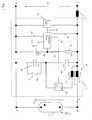
- Fig. 1 shows a circuit arrangement according to the invention, which is designed here as Zündscensan himself 1.
- the high-pressure gas discharge lamp 3 is connected, via which a lamp operating voltage U L drops during operation, the lamp current is indicated by I L.
- the ignition circuit 1 is connected via a designed as a throttle 2 magnetic ballast to the mains voltage U N.
- the circuit arrangement comprises a triggering circuit, which in the in Fig. 1 shown Embodiment, a surge capacitor 30, the primary-side coil winding 13 of a Zündübertragers 10 and a controllable switch 20 has.
- the series connection of the primary-side coil winding 13 and the switch 20 is connected in parallel to the surge capacitor 30.
- the secondary-side coil winding 11 of the Zündübertragers 10 is disposed in the supply line of the lamp.
- the surge capacitor 30 is connected in parallel with a capacitor 40 and a resistor 41 in series. This parallel connection serves to charge the surge capacitor 30.
- the circuit arrangement shown comprises a controller 50, which has a timer module as a subassembly.
- the controller 50 actuates the switch S1 for generating a primary-side ignition pulse in the Zündauslösesclien, which is superimposed pulse-transformed on the secondary side of the Zündübertragers the AC power supply to the lamp.
- the switch 20 is e.g. designed as a field effect transistor.
- the circuit arrangement has a series connection, which comprises at least the resistor 61 and the capacitor 60 and which is connected to the electrodes of the lamp 3 and insofar as this is connected in parallel.
- this series connection connected in parallel with the lamp also has the secondary-side coil winding 11.
- the Con-troller 50 is connected via the connecting lines 54, 55 for power supply.
- the control line 51 controls the switch 20 of the Zündauslöseschaltnikes.
- the controller 50 has a sensor line 53 which is at the voltage U C of the capacitor 60. The detected voltage on the line 53 U C is digitized in the controller via an analog-to-digital converter, not shown, so that the voltage at the capacitor 60 is ready for further processing binary coded in the controller 50.
- the timer 50 in the in Fig. 1 illustrated embodiment, a further control line 52, with which a executed as a field effect transistor second switch 70 is driven.
- the switch 70 together with the secondary winding 11 of the Zündübertragers 10 a series circuit which is connected in parallel to the lamp 3, so that the switch 70, the lamp can be short-circuited.
- the second switch can also be designed as a thyristor or triac, for example.
- Fig. 1 illustrated Zündscensan extract invention The functioning of in Fig. 1 illustrated Zündscensan extract invention will be described below.
- the switch S1 After charging the surge capacitor 30 controls the controller 50 at a time at which the mains voltage is above the lamp voltage, the switch S1 briefly to close and then to open again.
- the surge capacitor 30 serving as the input power source for the tripping circuit discharges via the primary-side coil winding 13 of the ignition transformer 10.
- the magnetization of the primary-side coil winding is transformed via the Zündübertragerkern 12 to the secondary-side coil winding 11 and the mains voltage superimposed.
- a secondary-side ignition pulse is thus applied to the lamp 3, so that it can ignite.
- the controller 50 continuously determines the degree of unbalance of the lamp operating voltage.
- the series connection of the secondary-side coil winding 11, the resistor 61 and the capacitor 60, which is connected to the electrodes of the lamp 3 is used.
- the secondary-side coil winding 11 does not interfere with the detection of this DC voltage component, since the former has a negligible DC resistance.
- the capacitor 60 is symmetrically charged or discharged.
- the voltage U C at the capacitor 60 is digitized by the controller 50 by means of an A / D converter, not shown, whose input is connected to the measuring line 53.
- the controller 50 on the capacitor 60 detects a DC voltage component identical to zero.
- the controller 50 measures a non-zero DC voltage component of the voltage U C , which is a measure of the unbalance of the lamp operating voltage and from the controller 50 with a predetermined value is compared. If, during operation of the lamp, this preset value is exceeded, the lamp 3 is switched off in order to avoid consequential damage, which could be caused for example due to excessive temperature development. For this purpose, the controller 50 controls the switch 70 to close via the control line 52.
- the controller 50 re-directs the switch 70 to open. Since the controller 50 has detected that the lamp is faulty, the control line 51 is blocked, so that the switch 20 in the Zündauslösesclien can not be controlled to close and thus not to generate a firing pulse.
- the controller 50 is set to re-initialize after the power is turned off and then turned on again, and then the switch 20 can again be driven to generate a primary-side firing pulse. It is assumed that after disconnecting the controller from the mains, the lamp replaced and after restarting the network, the new lamp can be operated as described.
- the controller 50 includes a timer device having, in the described embodiment, a count device for detecting the number of lamp firings and a counter for detecting the past ignition timing for a firing attempt.
- a timer device having, in the described embodiment, a count device for detecting the number of lamp firings and a counter for detecting the past ignition timing for a firing attempt.
- a count device for detecting the number of lamp firings
- a counter for detecting the past ignition timing for a firing attempt.
- the controller 50 will close a faulty lamp and omit further ignition attempts.
- an unillustrated memory area is provided in the controller 50, in which the permitted number of lamp ignitions or the allowable ignition time for a detonation attempt are stored.
- the allowed number of ignition attempts and / or the allowable ignition time is made in a Zünd bath of the determined measure for the unbalance of the lamp operating voltage. The lower the unbalance of the lamp operating voltage, the higher the number of permitted lamp ignitions or the permitted ignition time. If the measured unbalance of the lamp operating voltage approaches the limit value, the number of permitted ignition attempts or the permitted ignition time is correspondingly reduced in order to damage the magnetic ballast or ignition circuit when the lamp is in "end-of-life" state avoid.
- the circuit arrangement 1 does not comprise the magnetic ballast designed as a choke 2. In another embodiment of the invention, however, it is provided to integrate the ballast and the ignition circuit in a single unit, see Fig. 2 , This shows a second inventively designed circuit arrangement in which the ballast 2 and the ignition circuit are formed as a unit.
- Fig. 2 illustrated embodiment of the circuit arrangement is otherwise very similar to the in Fig. 1 constructed and differs from this otherwise only in the design of Zündauslöseschari.
- Its switch 20 is designed here as a passive, self-controlled switch.
- the in Fig. 1 does not comprise the magnetic ballast designed as a choke 2.
- Fig. 2 This shows a second inventively designed circuit arrangement in which the ballast 2 and the ignition circuit are formed as a unit.
- Fig. 2 illustrated embodiment of the circuit arrangement is otherwise very similar to the in Fig. 1 constructed and differs from this otherwise only in the design of Zündauslöseschari.
- Its switch 20 is designed here as a passive, self
- the 2 illustrated circuit compares the executed as Sidac or triac switch the voltage applied to it with a switch-internal comparator 21 and turns on exceeding a predetermined voltage value, here about 200 volts.
- a primary ignition pulse is triggered by the Discharge of the surge capacitor 30 is generated, the switch 20 opens again when its holding current is exceeded.
- the electrical design of the components is designed in such a way that here too the triggering circuit is set up for generating a plurality of ignition pulses within a network half-cycle.
- FIG. 2 Another difference of in Fig. 2 shown circuit arrangement in comparison to in Fig. 1 shown is that the controller 50 in Fig. 2 the generation of primary ignition pulses can block that can be controlled via the control line 51, a switch 80 for closing, which is arranged parallel to the surge capacitor 30. The trigger circuit is in turn blocked when, as described above, it has been detected that a predetermined amount of unbalance of the lamp operating voltage has been reached.
Claims (12)
- Circuit pour allumer une lampe à décharge haute pression connectée sur son entrée à un ballast magnétique pour fournir un courant d'alimentation alternant de la lampe, le circuit comprenant- un transformateur d'allumage connecté sur son premier côté à un circuit de déclenchement d'allumage et
disposé sur son deuxième côté entre le ballast et la lampe, pour transférer une impulsion d'allumage à la lampe,- un condensateur de choc et un premier moyen interrupteur, un couplage en série comprenant au moins le premier moyen interrupteur et un enroulement primaire du transformateur d'allumage étant connectés en parallèle avec le condensateur de choc dans le circuit de déclenchement d'allumage,caractérisé en ce qu'un circuit en série (70, 11) comportant un deuxième moyen interrupteur (70) commandable est connecté en parallèle avec la lampe (3) pour éteindre la lampe et en ce que sont prévus un moyen pour détecter la mesure de l'asymétrie de la tension de service de la lampe ainsi qu'un dispositif de commande (50) pour éteindre la lampe par la commande du deuxième moyen interrupteur en réponse à l'asymétrie détectée de la tension de service de la lampe. - Circuit selon la revendication 1, caractérisé en ce que le dispositif de commande (50) comporte un circuit minuteur pour commander le service d'allumage du circuit (1), avec un dispositif de compteur pour détecter le nombre d'allumages de la lampe et/ou un dispositif de compteur pour détecter la durée d'allumage pour un essai d'allumage.
- Circuit selon la revendication 1 ou 2, caractérisé en ce qu'un circuit en série (60, 61, 11) comportant au moins un condensateur (60) et une résistance (61) est connecté en parallèle avec la lampe et en ce qu'est prévu en outre un moyen pour détecter la tension sur le condensateur.
- Circuit selon la revendication 1, 2 ou 3, caractérisé en ce que le ballast magnétique est agencé comme une inductance (2) et en ce que le circuit en série disposé en parallèle avec la lampe (3) et incluant le deuxième moyen interrupteur ne comporte pas ladite inductance.
- Circuit selon l'une des revendications 2 à 4, autant que réfléchies sur la revendication 2, caractérisé en ce que des troisièmes moyens interrupteur (80) sont connectés en parallèle avec le condensateur de choc (3).
- Procédé pour opérer une lampe de décharge à haute pression connectée à un ballast magnétique pour fournir un courant d'alimentation alternant, comprenant un circuit d'allumage qui est inactivé après l'allumage de la lampe, caractérisé en ce que, pendant le service de la lampe (3), on détecte une mesure pour l'asymétrie de la tension d'alimentation de la lampe et puis compare la mesure détectée avec une valeur prédéterminée, la lampe étant mise en court-circuit pour éteindre la décharge de lampe lorsque la valeur prédéterminée est dépassée.
- Procédé selon la revendication 6, caractérisé en ce que la lampe (3) est mise en court-circuit pour un intervalle de temps prédétermine, et le court-cicuit est annulé après l'expiration de cet intervallle de temps.
- Procédé selon la revendication 6 ou 7, caractérisé en ce que l'arrangement de circuit d'allumage est verrouillé en même temps avec ou après la mise en court-circuit de la lampe (3).
- Procédé selon la revendication 8, caractérisé en ce que le verrouillage de l'arrangement de circuit d'allumage est annulé après la séparation de l'arrangement de cicuit d'allumage de l'alimentation et la connexion de l'arrangement de circuit d'allumage de nouveau avec l'alimentation.
- Procédé selon l'une des revendications 6 à 9, caractérisé en ce qu'on mémorise une mesure détectée pour le déséquilibre de tension d'alimentation de lampe.
- Procédé selon l'une des revendications 6 à 10, caractérisé en ce que pendant l'allumage de lampe une mesure détectée pour le déséquilibre de tension d'alimentation de lampe est considérée dans la fixation d'un nombre permis d'essais d'allumage avant que l'arrangement de circuit d'allumage soit verrouillé.
- Procédé selon l'une des revendications 6 à 11, caractérisé en ce que pendant l'allumage de la lampe une mesure détectée pour le déséquilibre de tension d'alimentation de lampe est considérée dans la fixation d'une durée d'allumage permise avant que l'arrangement de circuit d'allumage soit verrouillé.
Applications Claiming Priority (1)
| Application Number | Priority Date | Filing Date | Title |
|---|---|---|---|
| DE200610016827 DE102006016827A1 (de) | 2006-04-07 | 2006-04-07 | Schaltungsanordnung für Hochdruck-Gasentladungslampen |
Publications (3)
| Publication Number | Publication Date |
|---|---|
| EP1843645A2 EP1843645A2 (fr) | 2007-10-10 |
| EP1843645A3 EP1843645A3 (fr) | 2008-07-02 |
| EP1843645B1 true EP1843645B1 (fr) | 2015-03-25 |
Family
ID=38229302
Family Applications (1)
| Application Number | Title | Priority Date | Filing Date |
|---|---|---|---|
| EP20070007165 Not-in-force EP1843645B1 (fr) | 2006-04-07 | 2007-04-05 | Circuit pour lampes à décharge haute pression |
Country Status (2)
| Country | Link |
|---|---|
| EP (1) | EP1843645B1 (fr) |
| DE (1) | DE102006016827A1 (fr) |
Families Citing this family (4)
| Publication number | Priority date | Publication date | Assignee | Title |
|---|---|---|---|---|
| DE102010039487A1 (de) * | 2010-08-18 | 2012-02-23 | Osram Ag | Schaltungsanordnung und Verfahren zum Betrieb einer Gasentladungslampe |
| DE102010042776A1 (de) * | 2010-10-21 | 2012-04-26 | Bag Engineering Gmbh | Vorrichtung und Verfahren zur Zündung von HID-Lampen mit CWA |
| DE102010043081A1 (de) * | 2010-10-28 | 2012-05-03 | Bag Engineering Gmbh | Zündschaltungsanordnung zum Zünden einer Entladungslampe wie einer Hochdrucklampe |
| AT12721U1 (de) * | 2011-04-22 | 2012-10-15 | Tridonic Gmbh & Co Kg | Vorrichtung zum betreiben einer hochdruckentladungslampe |
Family Cites Families (4)
| Publication number | Priority date | Publication date | Assignee | Title |
|---|---|---|---|---|
| US4207500A (en) * | 1978-12-14 | 1980-06-10 | Area Lighting Research, Inc. | Cut-off arrangement for and method of protecting a ballast-starter circuit from high pressure sodium lamp cycling malfunction |
| DE19531622B4 (de) | 1995-08-28 | 2011-01-13 | Tridonicatco Gmbh & Co. Kg | Zündschaltung für eine Hochdruck-Gasentladungslampe |
| DE19531623B4 (de) * | 1995-08-28 | 2010-09-23 | Tridonicatco Gmbh & Co. Kg | Verfahren und Schaltungsanordnung zum Zünden einer Hochdruck-Gasentladungslampe |
| DE102004045834A1 (de) * | 2004-09-22 | 2006-03-23 | Bag Electronics Gmbh | Zündgerät |
-
2006
- 2006-04-07 DE DE200610016827 patent/DE102006016827A1/de not_active Withdrawn
-
2007
- 2007-04-05 EP EP20070007165 patent/EP1843645B1/fr not_active Not-in-force
Also Published As
| Publication number | Publication date |
|---|---|
| EP1843645A3 (fr) | 2008-07-02 |
| EP1843645A2 (fr) | 2007-10-10 |
| DE102006016827A1 (de) | 2007-10-11 |
Similar Documents
| Publication | Publication Date | Title |
|---|---|---|
| EP1519638B1 (fr) | Méthode pour commander une lampe à décharge basse pression | |
| DE4129557C2 (de) | Stromversorgungsschaltung für eine Gasentladungslampe in einem Fahrzeug | |
| DE4412518C2 (de) | Schaltungsanordnung zum Zünden und Betreiben einer Hochdruck-Entladungslampe | |
| EP0515977B1 (fr) | Ballast électronique pour lampe à décharge haute-pression utilisée dans l'automobile | |
| EP0677981A1 (fr) | Ballast, avec dispositif de reconnaissance de changement de lampe, pour tubes à décharge | |
| EP2377372B1 (fr) | Méthode, appareil et système d'éclairage | |
| EP1103166B1 (fr) | Ballast electronique destine a au moins une lampe a decharge basse tension | |
| EP1843645B1 (fr) | Circuit pour lampes à décharge haute pression | |
| DE19531622B4 (de) | Zündschaltung für eine Hochdruck-Gasentladungslampe | |
| EP1901591B1 (fr) | Allumage de lampes à décharge dans des conditions environnementales variables | |
| DE19531623B4 (de) | Verfahren und Schaltungsanordnung zum Zünden einer Hochdruck-Gasentladungslampe | |
| EP0615267A1 (fr) | Circuit de test des contacts d'interrupteur ou de relais | |
| EP2047720A1 (fr) | Procédé et dispositif de contrôle d'au moins un tube fluorescent | |
| EP1424881A1 (fr) | Dispositif et méthode pour commander une lampe fluorescente | |
| EP1992203B1 (fr) | Ballasst électronique et procédé de fonctionnement d'une lampe électrique | |
| EP2011373B1 (fr) | Appareil d'allumage à superposition pour lampes à décharge haute pression | |
| EP2796012B1 (fr) | Procédé, appareillage d'alimentation et système d'éclairage, avec détection d'effet de redressement de lampes | |
| EP0759684A1 (fr) | Amorceur pour une lampe à décharge haute-pression | |
| DE3723278C2 (fr) | ||
| DE1913715A1 (de) | Steuereinrichtung fuer eine Feuerungsanlage | |
| EP2208401B1 (fr) | Ballast électronique et procédé pour faire fonctionner au moins une première et une deuxième lampes à décharge | |
| DE102005058222A1 (de) | Verfahren zur Fehlerdetektion beim Betrieb von Hochdruckentladungslampen an EVGs | |
| DE2809994C3 (de) | Elektronische Sicherheitszeitschaltung für Gas- oder Ölbrenner | |
| DE19819671B4 (de) | Schaltungsanordnung zum Schutz von Leuchtstofflampen und elektronischem Vorschaltgerät | |
| DE202005003632U1 (de) | Zündschaltungsanordnung mit erhöhter Ausfallsicherheit |
Legal Events
| Date | Code | Title | Description |
|---|---|---|---|
| PUAI | Public reference made under article 153(3) epc to a published international application that has entered the european phase |
Free format text: ORIGINAL CODE: 0009012 |
|
| AK | Designated contracting states |
Kind code of ref document: A2 Designated state(s): AT BE BG CH CY CZ DE DK EE ES FI FR GB GR HU IE IS IT LI LT LU LV MC MT NL PL PT RO SE SI SK TR |
|
| AX | Request for extension of the european patent |
Extension state: AL BA HR MK YU |
|
| PUAL | Search report despatched |
Free format text: ORIGINAL CODE: 0009013 |
|
| AK | Designated contracting states |
Kind code of ref document: A3 Designated state(s): AT BE BG CH CY CZ DE DK EE ES FI FR GB GR HU IE IS IT LI LT LU LV MC MT NL PL PT RO SE SI SK TR |
|
| AX | Request for extension of the european patent |
Extension state: AL BA HR MK RS |
|
| RIC1 | Information provided on ipc code assigned before grant |
Ipc: H05B 41/04 20060101ALI20080528BHEP Ipc: H05B 41/288 20060101AFI20070718BHEP |
|
| 17P | Request for examination filed |
Effective date: 20080806 |
|
| 17Q | First examination report despatched |
Effective date: 20080912 |
|
| AKX | Designation fees paid |
Designated state(s): AT BE BG CH CY CZ DE DK EE ES FI FR GB GR HU IE IS IT LI LT LU LV MC MT NL PL PT RO SE SI SK TR |
|
| GRAP | Despatch of communication of intention to grant a patent |
Free format text: ORIGINAL CODE: EPIDOSNIGR1 |
|
| INTG | Intention to grant announced |
Effective date: 20141010 |
|
| GRAS | Grant fee paid |
Free format text: ORIGINAL CODE: EPIDOSNIGR3 |
|
| GRAA | (expected) grant |
Free format text: ORIGINAL CODE: 0009210 |
|
| AK | Designated contracting states |
Kind code of ref document: B1 Designated state(s): AT BE BG CH CY CZ DE DK EE ES FI FR GB GR HU IE IS IT LI LT LU LV MC MT NL PL PT RO SE SI SK TR |
|
| REG | Reference to a national code |
Ref country code: GB Ref legal event code: FG4D Free format text: NOT ENGLISH |
|
| REG | Reference to a national code |
Ref country code: CH Ref legal event code: EP |
|
| REG | Reference to a national code |
Ref country code: IE Ref legal event code: FG4D Free format text: LANGUAGE OF EP DOCUMENT: GERMAN |
|
| REG | Reference to a national code |
Ref country code: DE Ref legal event code: R096 Ref document number: 502007013813 Country of ref document: DE Effective date: 20150507 |
|
| REG | Reference to a national code |
Ref country code: AT Ref legal event code: REF Ref document number: 718519 Country of ref document: AT Kind code of ref document: T Effective date: 20150515 |
|
| PG25 | Lapsed in a contracting state [announced via postgrant information from national office to epo] |
Ref country code: SE Free format text: LAPSE BECAUSE OF FAILURE TO SUBMIT A TRANSLATION OF THE DESCRIPTION OR TO PAY THE FEE WITHIN THE PRESCRIBED TIME-LIMIT Effective date: 20150325 Ref country code: LT Free format text: LAPSE BECAUSE OF FAILURE TO SUBMIT A TRANSLATION OF THE DESCRIPTION OR TO PAY THE FEE WITHIN THE PRESCRIBED TIME-LIMIT Effective date: 20150325 Ref country code: FI Free format text: LAPSE BECAUSE OF FAILURE TO SUBMIT A TRANSLATION OF THE DESCRIPTION OR TO PAY THE FEE WITHIN THE PRESCRIBED TIME-LIMIT Effective date: 20150325 |
|
| REG | Reference to a national code |
Ref country code: LT Ref legal event code: MG4D |
|
| PG25 | Lapsed in a contracting state [announced via postgrant information from national office to epo] |
Ref country code: GR Free format text: LAPSE BECAUSE OF FAILURE TO SUBMIT A TRANSLATION OF THE DESCRIPTION OR TO PAY THE FEE WITHIN THE PRESCRIBED TIME-LIMIT Effective date: 20150626 Ref country code: LV Free format text: LAPSE BECAUSE OF FAILURE TO SUBMIT A TRANSLATION OF THE DESCRIPTION OR TO PAY THE FEE WITHIN THE PRESCRIBED TIME-LIMIT Effective date: 20150325 |
|
| PG25 | Lapsed in a contracting state [announced via postgrant information from national office to epo] |
Ref country code: NL Free format text: LAPSE BECAUSE OF FAILURE TO SUBMIT A TRANSLATION OF THE DESCRIPTION OR TO PAY THE FEE WITHIN THE PRESCRIBED TIME-LIMIT Effective date: 20150325 |
|
| PG25 | Lapsed in a contracting state [announced via postgrant information from national office to epo] |
Ref country code: CZ Free format text: LAPSE BECAUSE OF FAILURE TO SUBMIT A TRANSLATION OF THE DESCRIPTION OR TO PAY THE FEE WITHIN THE PRESCRIBED TIME-LIMIT Effective date: 20150325 Ref country code: ES Free format text: LAPSE BECAUSE OF FAILURE TO SUBMIT A TRANSLATION OF THE DESCRIPTION OR TO PAY THE FEE WITHIN THE PRESCRIBED TIME-LIMIT Effective date: 20150325 Ref country code: RO Free format text: LAPSE BECAUSE OF FAILURE TO SUBMIT A TRANSLATION OF THE DESCRIPTION OR TO PAY THE FEE WITHIN THE PRESCRIBED TIME-LIMIT Effective date: 20150325 Ref country code: EE Free format text: LAPSE BECAUSE OF FAILURE TO SUBMIT A TRANSLATION OF THE DESCRIPTION OR TO PAY THE FEE WITHIN THE PRESCRIBED TIME-LIMIT Effective date: 20150325 Ref country code: PT Free format text: LAPSE BECAUSE OF FAILURE TO SUBMIT A TRANSLATION OF THE DESCRIPTION OR TO PAY THE FEE WITHIN THE PRESCRIBED TIME-LIMIT Effective date: 20150727 Ref country code: SK Free format text: LAPSE BECAUSE OF FAILURE TO SUBMIT A TRANSLATION OF THE DESCRIPTION OR TO PAY THE FEE WITHIN THE PRESCRIBED TIME-LIMIT Effective date: 20150325 |
|
| PG25 | Lapsed in a contracting state [announced via postgrant information from national office to epo] |
Ref country code: PL Free format text: LAPSE BECAUSE OF FAILURE TO SUBMIT A TRANSLATION OF THE DESCRIPTION OR TO PAY THE FEE WITHIN THE PRESCRIBED TIME-LIMIT Effective date: 20150325 Ref country code: IS Free format text: LAPSE BECAUSE OF FAILURE TO SUBMIT A TRANSLATION OF THE DESCRIPTION OR TO PAY THE FEE WITHIN THE PRESCRIBED TIME-LIMIT Effective date: 20150725 Ref country code: MC Free format text: LAPSE BECAUSE OF FAILURE TO SUBMIT A TRANSLATION OF THE DESCRIPTION OR TO PAY THE FEE WITHIN THE PRESCRIBED TIME-LIMIT Effective date: 20150325 |
|
| REG | Reference to a national code |
Ref country code: CH Ref legal event code: PL |
|
| REG | Reference to a national code |
Ref country code: DE Ref legal event code: R097 Ref document number: 502007013813 Country of ref document: DE |
|
| REG | Reference to a national code |
Ref country code: IE Ref legal event code: MM4A |
|
| PG25 | Lapsed in a contracting state [announced via postgrant information from national office to epo] |
Ref country code: DK Free format text: LAPSE BECAUSE OF FAILURE TO SUBMIT A TRANSLATION OF THE DESCRIPTION OR TO PAY THE FEE WITHIN THE PRESCRIBED TIME-LIMIT Effective date: 20150325 Ref country code: IT Free format text: LAPSE BECAUSE OF FAILURE TO SUBMIT A TRANSLATION OF THE DESCRIPTION OR TO PAY THE FEE WITHIN THE PRESCRIBED TIME-LIMIT Effective date: 20150325 Ref country code: CH Free format text: LAPSE BECAUSE OF NON-PAYMENT OF DUE FEES Effective date: 20150430 Ref country code: LI Free format text: LAPSE BECAUSE OF NON-PAYMENT OF DUE FEES Effective date: 20150430 |
|
| PLBE | No opposition filed within time limit |
Free format text: ORIGINAL CODE: 0009261 |
|
| REG | Reference to a national code |
Ref country code: FR Ref legal event code: ST Effective date: 20151231 |
|
| STAA | Information on the status of an ep patent application or granted ep patent |
Free format text: STATUS: NO OPPOSITION FILED WITHIN TIME LIMIT |
|
| GBPC | Gb: european patent ceased through non-payment of renewal fee |
Effective date: 20150625 |
|
| PG25 | Lapsed in a contracting state [announced via postgrant information from national office to epo] |
Ref country code: FR Free format text: LAPSE BECAUSE OF NON-PAYMENT OF DUE FEES Effective date: 20150526 |
|
| 26N | No opposition filed |
Effective date: 20160105 |
|
| PG25 | Lapsed in a contracting state [announced via postgrant information from national office to epo] |
Ref country code: GB Free format text: LAPSE BECAUSE OF NON-PAYMENT OF DUE FEES Effective date: 20150625 Ref country code: IE Free format text: LAPSE BECAUSE OF NON-PAYMENT OF DUE FEES Effective date: 20150405 |
|
| PG25 | Lapsed in a contracting state [announced via postgrant information from national office to epo] |
Ref country code: SI Free format text: LAPSE BECAUSE OF FAILURE TO SUBMIT A TRANSLATION OF THE DESCRIPTION OR TO PAY THE FEE WITHIN THE PRESCRIBED TIME-LIMIT Effective date: 20150325 |
|
| REG | Reference to a national code |
Ref country code: AT Ref legal event code: MM01 Ref document number: 718519 Country of ref document: AT Kind code of ref document: T Effective date: 20150405 |
|
| PG25 | Lapsed in a contracting state [announced via postgrant information from national office to epo] |
Ref country code: AT Free format text: LAPSE BECAUSE OF NON-PAYMENT OF DUE FEES Effective date: 20150405 |
|
| PG25 | Lapsed in a contracting state [announced via postgrant information from national office to epo] |
Ref country code: MT Free format text: LAPSE BECAUSE OF FAILURE TO SUBMIT A TRANSLATION OF THE DESCRIPTION OR TO PAY THE FEE WITHIN THE PRESCRIBED TIME-LIMIT Effective date: 20150325 |
|
| PG25 | Lapsed in a contracting state [announced via postgrant information from national office to epo] |
Ref country code: BG Free format text: LAPSE BECAUSE OF FAILURE TO SUBMIT A TRANSLATION OF THE DESCRIPTION OR TO PAY THE FEE WITHIN THE PRESCRIBED TIME-LIMIT Effective date: 20150325 Ref country code: HU Free format text: LAPSE BECAUSE OF FAILURE TO SUBMIT A TRANSLATION OF THE DESCRIPTION OR TO PAY THE FEE WITHIN THE PRESCRIBED TIME-LIMIT; INVALID AB INITIO Effective date: 20070405 |
|
| PG25 | Lapsed in a contracting state [announced via postgrant information from national office to epo] |
Ref country code: CY Free format text: LAPSE BECAUSE OF FAILURE TO SUBMIT A TRANSLATION OF THE DESCRIPTION OR TO PAY THE FEE WITHIN THE PRESCRIBED TIME-LIMIT Effective date: 20150325 |
|
| PG25 | Lapsed in a contracting state [announced via postgrant information from national office to epo] |
Ref country code: BE Free format text: LAPSE BECAUSE OF NON-PAYMENT OF DUE FEES Effective date: 20150430 |
|
| PG25 | Lapsed in a contracting state [announced via postgrant information from national office to epo] |
Ref country code: TR Free format text: LAPSE BECAUSE OF FAILURE TO SUBMIT A TRANSLATION OF THE DESCRIPTION OR TO PAY THE FEE WITHIN THE PRESCRIBED TIME-LIMIT Effective date: 20150325 |
|
| PG25 | Lapsed in a contracting state [announced via postgrant information from national office to epo] |
Ref country code: LU Free format text: LAPSE BECAUSE OF NON-PAYMENT OF DUE FEES Effective date: 20150405 |
|
| PGFP | Annual fee paid to national office [announced via postgrant information from national office to epo] |
Ref country code: DE Payment date: 20180628 Year of fee payment: 12 |
|
| REG | Reference to a national code |
Ref country code: DE Ref legal event code: R119 Ref document number: 502007013813 Country of ref document: DE |
|
| PG25 | Lapsed in a contracting state [announced via postgrant information from national office to epo] |
Ref country code: DE Free format text: LAPSE BECAUSE OF NON-PAYMENT OF DUE FEES Effective date: 20191101 |