EP1983120A2 - Fugenabdichtungselement - Google Patents
Fugenabdichtungselement Download PDFInfo
- Publication number
- EP1983120A2 EP1983120A2 EP08007618A EP08007618A EP1983120A2 EP 1983120 A2 EP1983120 A2 EP 1983120A2 EP 08007618 A EP08007618 A EP 08007618A EP 08007618 A EP08007618 A EP 08007618A EP 1983120 A2 EP1983120 A2 EP 1983120A2
- Authority
- EP
- European Patent Office
- Prior art keywords
- polymer layer
- sealing element
- joint sealing
- adhesive
- element according
- Prior art date
- Legal status (The legal status is an assumption and is not a legal conclusion. Google has not performed a legal analysis and makes no representation as to the accuracy of the status listed.)
- Granted
Links
Images
Classifications
-
- E—FIXED CONSTRUCTIONS
- E04—BUILDING
- E04B—GENERAL BUILDING CONSTRUCTIONS; WALLS, e.g. PARTITIONS; ROOFS; FLOORS; CEILINGS; INSULATION OR OTHER PROTECTION OF BUILDINGS
- E04B1/00—Constructions in general; Structures which are not restricted either to walls, e.g. partitions, or floors or ceilings or roofs
- E04B1/62—Insulation or other protection; Elements or use of specified material therefor
- E04B1/66—Sealings
- E04B1/68—Sealings of joints, e.g. expansion joints
- E04B1/6806—Waterstops
-
- E—FIXED CONSTRUCTIONS
- E04—BUILDING
- E04B—GENERAL BUILDING CONSTRUCTIONS; WALLS, e.g. PARTITIONS; ROOFS; FLOORS; CEILINGS; INSULATION OR OTHER PROTECTION OF BUILDINGS
- E04B1/00—Constructions in general; Structures which are not restricted either to walls, e.g. partitions, or floors or ceilings or roofs
- E04B1/0007—Base structures; Cellars
-
- E—FIXED CONSTRUCTIONS
- E04—BUILDING
- E04B—GENERAL BUILDING CONSTRUCTIONS; WALLS, e.g. PARTITIONS; ROOFS; FLOORS; CEILINGS; INSULATION OR OTHER PROTECTION OF BUILDINGS
- E04B1/00—Constructions in general; Structures which are not restricted either to walls, e.g. partitions, or floors or ceilings or roofs
- E04B1/16—Structures made from masses, e.g. of concrete, cast or similarly formed in situ with or without making use of additional elements, such as permanent forms, substructures to be coated with load-bearing material
- E04B1/161—Structures made from masses, e.g. of concrete, cast or similarly formed in situ with or without making use of additional elements, such as permanent forms, substructures to be coated with load-bearing material with vertical and horizontal slabs, both being partially cast in situ
Definitions
- the invention relates to a joint sealing element for sealing a joint formed between two concreting sections.
- construction joints In the manufacture of structures, for example, two successive concreting sections create so-called construction joints. Such construction joints entail the danger that they will not be reliably sealed over the life of a building, so that water can penetrate into a structure along such a construction joint. To seal such construction joints as well as for the production of water-impermeable concrete structures, these construction joints are permanently sealed by using joint sealing elements or joint plates. These form a barrier against penetrating water and moisture, so that a seal is given.
- a joint plate comprising a strip-shaped coating of water-swellable polymer material.
- the swelling of the water-swellable polymer material after setting in concrete is to be delayed until the hardening of the concrete has progressed sufficiently.
- Such joint plates are intended to seal the cracks in the working joint by swelling the polymer material.
- a joint plate in which a coating is applied to a galvanized carrier sheet having a sealing material.
- This sealing material consists of cement and / or calcium hydroxide.
- a plastic dispersion is provided as adhesion promoter.
- a seal is to be given by the fact that the cement and / or calcium hydroxide formed on the support plate in conjunction with water during concreting in a crystallization process water-insoluble calcium carbonate. This should cause a crystallization of the cracks.
- the sealing effect in this case depends on the formation of the water-insoluble calcium carbonate, which in turn is dependent on the incorporation of the sealing material in the bonding agent on the support,
- the invention has the object of developing a joint sealing element to the effect that a secure and permanent sealing of construction joints is possible.
- the joint sealing element consists of a carrier element, an adhesive polymer layer and a protective film.
- the production of such a carrier element is inexpensive.
- the formation of the adhesive polymer layer also has the advantage that a simple application is provided on the carrier element and on the other hand, a very good, complete and permanent sealing effect is formed to the adjoining concrete surface.
- this adhesive polymer layer has a certain elasticity, so that a stress reduction between the support element and the adjacent thereto Concrete surface can be done, which additionally increases the sealing effect.
- the joint sealing element which has an adhesive polymer layer which is provided with acidic reactive groups and which are suitable to connect via a chemical compound at least one adjacent to the polymer layer concrete surface, a complete and permanent sealing effect in the Häfuge achieved. Due to the presence of the acidic reactive groups on the polymer layer, adhesion is achieved during concreting of a concreting section at least between the concrete surface adjacent to the polymer layer and the surface adjacent to the polymer layer. As a result, at least in the boundary region between the polymer layer and the adjoining concrete surface a water-impermeable connection can be achieved. In addition, an at least partially elastic bond may be given by the adhesion between the polymer layer and the adjacent concrete surface.
- the polymer layer is enriched with reactive carboxyl groups.
- the polymer layer is preferably made of a UV-crosslinked polymer. This makes it possible, on the one hand, to achieve an elastic and, secondly, an aging-resistant polymer layer, in particular an adhesive polymer layer.
- the adhesive polymer layer is produced on a polyacrylate basis.
- a particularly suitable embodiment for a polymer layer having an adhesive or tacky surface can be provided on both sides of the polymer layer.
- the polymer layer has a thickness of 0.1 mm to 2 mm.
- the thickness of 0.5 mm to 1.2 mm is provided.
- Such thicknesses allow on the one hand a low construction height and on the other hand good adhesion properties on the support element and concrete.
- the requirements for heat aging are met by such thicknesses.
- such a polymer layer has no restriction in tackiness on heat aging in a period of seven days at a temperature of 70 °.
- the adhesive polymer layer is insoluble in water and in alkaline medium. As a result, very good and durable seals can be created.
- the adhesive polymer layer is free of butyl or free of butyl with bitumen. As a result, a simple disposal can be given.
- the polymer layer has the advantage that no toxic properties are present.
- the adhesive polymer layer can be processed at a temperature range of less than 5 ° C.
- the adhesive film can be processed very well at a temperature range of -20 ° C to + 5 ° C. This is necessary in order to connect the individual sections of the joint sealing elements along a concreting section.
- a tight joint where two adjoining joint sealing elements overlap in a joint area can be formed without preheating by gluing.
- a heating with a gas flame is required at temperatures below 5 ° C.
- the adhesive polymer layer is formed as an adhesive film.
- the polymer layer is made exclusively of a sticky material and as an elastic film with a relatively large elongation and formed very good adhesive properties.
- Such an adhesive film may also be formed and applied by spraying, laminating, rolling or the like.
- the adhesive polymer layer has a foamed core and an adhesive film or an adhesive coating is applied on both sides.
- This alternative embodiment allows a thicker or higher structure of the coating in a cost effective manner.
- the foamed core is preferably closed cell.
- the polymer layer is made of a foamed adhesive agent. This allows the adhesive itself to have a foamed core and an outer tacky surface.
- the joint sealing element preferably has a removable protective film, which is provided on the adhesive polymer layer and formed in two parts.
- the joint sealing elements are usually vertically aligned on a reinforcement for a bottom plate for sealing a first concreting section introduced. So that a connection of the adjacent to the joint sealing element concrete surface of the first concreting section can take place, a first strip of the protective film is peeled off. The further strip of the protective film is removed only before the introduction of the second concreting section, such as a side wall on a base plate. So that a simple and complete, especially fast removal of the strips can be done, the protective film is made of highly tear-resistant material.
- the protective film is siliconized at least on a side facing the adhesive film or adhesive polymer layer.
- the joint sealing element preferably comprises a carrier element of an untreated metallic material, such as steel sheet, a plastic profile, a mineral material, in particular fiber cement.
- an untreated metallic material such as steel sheet, a plastic profile, a mineral material, in particular fiber cement.
- a carrier element of an untreated metallic material such as steel sheet, a plastic profile, a mineral material, in particular fiber cement.
- galvanized steel sheets or the like can be used.
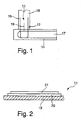
- an inventive joint sealing element 11 is arranged in the region of a working joint 12.
- the joint sealing element 11 is fixed on a reinforcement 14 before concreting.
- the joint sealing element 11 is preferably arranged between a connection reinforcement 16, which is wired to the reinforcement 14.
- a bottom plate is concreted as a first concreting section 17.
- the second concreting section 18 is concreted, for example in the form of a wall.
- the joint sealing element 11 seals the working joint 12 between the first and second concreting sections 17, 18.
- This carrier element 19 is for example made of metal, plastic, of a woven or knitted fabric, of a composite material of plastic and / or metal and / or textile material and / or mineral material and / or wood educated.
- a coating 20 is provided as strips along the longitudinal direction of the support element 19. This coating 20 extends at least partially, preferably completely, over the entire width of the carrier element 19 or over the entire height of the carrier element 19.
- the coating 20 consists of a polymer layer which, preferably formed on both sides adhesive, so that this polymer layer with a side surface the side surface of the support element 19 adheres.
- the opposite side surface is provided with a peelable protective film 21.
- the protective film 21 is preferably made of HDPE and has, for example, a thickness of 50 .mu.m to 400 .mu.m, in particular 100 .mu.m to 150 .mu.m. For easy stripping, at least the side of the protective film 21 facing the polymer layer is siliconized.
- This protective film 21 is preferably formed in two parts and in particular has two strips of equal width, so that after insertion of the joint sealing element 11 on the reinforcement 14, first the lower half of the protective film 11 is peeled off to introduce the first concreting section 17. During the concreting of the first concreting section 17, a watertight connection takes place due to the inventive design of the adhesive polymer layer.
- a connection between the polymer layer and the adjoining concrete, at least the adjoining concrete surface takes place via an ester group.
- This compound is achieved in particular in the case of a polymer layer based on acrylate, in which case water is formed as waste product and is harmless for the setting of the concrete.
- the acylate-based polymer layer may include reactive carboxyl groups.
- the polymer layer preferably has a thickness of between 0.1 mm to 2 mm, in particular 0.5 mm to 1.2 mm.
- the polymer layer is elastic to a certain extent, so that after Hardening of the concrete occurring stresses between the support member 19 and the adjoining concrete surface can be reduced.
- the adhesive polymer layer is formed as Ktebstofffilm.
- the adhesive film can absorb strains in the range between 0.1 mm and 0.4 mm, in which area in particular the maximum forces of adhesion are achieved.
- the adhesive film can remain both on the one hand on the support member 19 and on the other hand adhere to the adjacent concrete surface at voltages occurring in this area on the one hand.
- the adhesive film has, for example, an adhesive tensile strength to the support element 19, which lie in a range of 0.18 N / mm 2 to 0.3 N / mm 2 .
- the adhesive tensile strength of the coating on the concrete is, for example, in a range of 0.25 N / mm 2 to 0.4 N / mm 2 .
- the adhesive polymer layer can also have a foamed core which is provided on both sides with an adhesive or adhesive film or adhesive coating, so that this foamed core is fastened on the support element 19 on the one hand and adheres to the adjacent concrete surface on the other hand.
- the adhesive polymer layer is formed from a foamed adhesive material, so that the entire foamed adhesive is tacky and has an adhesive surface.
- this adhesive polymer layer can be applied directly to the carrier element 19 as a belt / web material, in which the carrier element 19 and the polymer layer are driven at the same web speed and run between two pressure rollers.
- the polymer layer is preferably unilaterally provided with the protective film, which is siliconized on both sides, so that a simple unrolling and sticking of the adhesive film onto the carrier element 19 is enabled.
- This polymer layer may be further applied by spraying, laminating, dipping or the like.
- a granular material such as blast furnace slag, quartz sand, silicon carbide, glass, ceramic, porcelain or metallic particles are scattered and / or partially incorporated.
- this granular material is applied in a central region over the height of a joint sealing element.
- the proportion of granular material increasingly decreases, so that a respective outer edge strip remains, which is formed exclusively from the adhesive polymer layer, in order to achieve a good seal with the concrete surface.
Landscapes
- Engineering & Computer Science (AREA)
- Architecture (AREA)
- Physics & Mathematics (AREA)
- Electromagnetism (AREA)
- Civil Engineering (AREA)
- Structural Engineering (AREA)
- Building Environments (AREA)
- Gasket Seals (AREA)
- Adhesives Or Adhesive Processes (AREA)
Abstract
Description
- Die Erfindung betrifft ein Fugenabdichtungselement zum Abdichten einer zwischen zwei Betonierabschnitten ausgebildeten Fuge.
- Bei der Herstellung von Bauwerken entstehen beispielsweise bei zwei aufeinander folgenden Betonierabschnitten sogenannte Arbeitsfugen. Solche Arbeitsfugen bergen die Gefahr in sich, dass diese über die Lebensdauer eines Bauwerkes nicht zuverlässig dicht sind, so dass entlang einer solchen Arbeitsfuge Wasser in ein Bauwerk eindringen kann. Zur Abdichtung solcher Arbeitsfugen sowie zur Herstellung von wasserundurchlässigen Betonkonstruktionen werden diese Arbeitsfugen dauerhaft abgedichtet, indem Fugenabdichtungselemente oder Fugenbleche eingesetzt werden. Diese bilden eine Barriere gegen eindringendes Wasser und Feuchtigkeit, so dass eine Abdichtung gegeben ist.
- Zur Erhöhung der Abdichtwirkung wird beispielsweise gemäß der
DE 297 10 007 U1 ein Fugenblech vorschlagen, welches eine streifenförmige Beschichtung aus wasserquellfähigem Polymermaterial umfasst. Das Aufquellen des wasserquellfähigen Polymermaterials nach dem Einbetonieren soll dabei so lange verzögert werden, bis die Aushärtung des Betons genügend fortgeschritten ist. Solche Fugenbleche sollen durch Quellen des Polymermaterials die Risse in der Arbeitsfuge abdichten. - Durch die
DE 20 2004 003 189 U1 ist des Weiteren ein Fugenblech bekannt geworden, bei welchem eine Beschichtung auf einem verzinkten Trägerblech aufgebracht ist, die ein Abdichtmaterial aufweist. Dieses Abdichtmaterial besteht aus Zement und/oder Calciumhydroxid. Zur Aufnahme von Zement und/oder Calciumhydroxid ist als Haftvermittler eine Kunststoffdispersion vorgesehen. Eine Abdichtung soll dadurch gegeben sein, dass der Zement und/oder das Calciumhydroxid auf dem Trägerblech in Verbindung mit Wasser während dem Betonieren in einem Kristallisationsprozess wasserunlösliches Calciumcarbonat ausbildet. Dadurch soll eine Auskristallisation der Risse erfolgen. Die Abdichtwirkung ist hierbei von der Ausbildung des wasserunlöslichen Calciumcarbonats abhängig, das wiederum in Abhängigkeit von der Einbindung des Abdichtmaterials in dem Haftvermittler auf dem Träger steht, - Der Erfindung liegt die Aufgabe zugrunde, ein Fugenabdichtungselement dahingehend weiterzubilden, dass eine sichere und dauerhafte Abdichtung von Arbeitsfugen ermöglicht wird.
- Diese Aufgabe wird erfindungsgemäß durch die Merkmale des Anspruchs 1 gelöst, Durch die erfindungsgemäße Ausgestaltung des Fugenabdichtungselementes wird ein sehr einfacher konstruktiver Aufbau erzielt, bei dem das Fugenabdichtungselement aus einem Trägerelement, aus einer haftenden Polymerschicht und einer Schutzfolie besteht. Dadurch ist die Herstellung eines solchen Trägerelementes kostengünstig. Die Ausbildung der haftenden Polymerschicht weist darüber hinaus den Vorteil auf, dass eine einfache Aufbringung auf dem Trägerelement gegeben ist und andererseits eine sehr gute, vollständige und dauerhafte Abdichtwirkung zur daran angrenzenden Betonoberfläche gebildet wird. Darüber hinaus weist diese haftende Polymerschicht eine gewisse Elastizität auf, so dass ein Spannungsabbau zwischen dem Trägerelement und der daran angrenzenden Betonoberfläche erfolgen kann, wodurch zusätzlich die Dichtwirkung erhöht wird.
- Durch die bevorzugte Ausgestaltung des Fugenabdichtungselementes, welches eine haftende Polymerschicht aufweist, die mit aciden reaktiven Gruppen versehen ist und die geeignet sind, sich über eine chemische Verbindung zumindest mit einer an die Polymerschicht angrenzenden Betonoberfläche zu verbinden, wird eine vollständige und dauerhafte Abdichtwirkung in der Arbeitsfuge erzielt. Durch das Vorhandensein der aciden reaktiven Gruppen auf der Polymerschicht wird während dem Betonieren eines Betonierabschnittes zumindest zwischen der an die Polymerschicht angrenzende Betonoberfläche und der an die Polymerschicht angrenzenden Oberfläche eine Adhäsion erzielt. Dadurch kann zumindest im Grenzbereich zwischen der Polymerschicht und der daran angrenzenden Betonoberfläche eine wasserundurchlässige Verbindung erzielt werden. Zusätzlich kann eine, zumindest teilweise elastische Verbindung durch die Adhäsion zwischen der Polymerschicht und der angrenzenden Betonoberfläche gegeben sein.
- Nach einer bevorzugten Ausgestaltung der Erfindung ist vorgesehen, dass die Polymerschicht mit reaktiven Carboxylgruppen angereichert ist. Dadurch wird während dem Aushärten des Betons eine Wechselwirkung zwischen dem Beton beziehungsweise der Oberfläche des Betons und der Polymerschicht erzielt, wobei unter Bildung von Estergruppen eine Verbindung zwischen der Polymerschicht und der daran angrenzenden Betonoberfläche erzielt wird.
- Die Polymerschicht wird bevorzugt aus einem UV-vernetzten Polymer hergestellt. Dadurch lässt sich zum einen eine elastische und zum anderen eine alterungsbeständige Polymerschicht, insbesondere haftende Polymerschicht, erzielen.
- Des Weiteren ist bevorzugt vorgesehen, dass die haftende Polymerschicht auf einer Polyacrylatbasis hergestellt ist. Dadurch kann eine besonders geeignete Ausgestaltung für eine Polymerschicht mit einer haftenden oder klebrigen Oberfläche auf beiden Seiten der Polymerschicht geschaffen sein.
- Des Weiteren ist bevorzugt vorgesehen, dass die Polymerschicht eine Dicke von 0,1 mm bis 2 mm aufweist. Bevorzugt ist die Dicke von 0,5 mm bis 1,2 mm vorgesehen. Solche Dicken ermöglichen einerseits eine geringe Aufbauhöhe und andererseits gute Hafteigenschaften am Trägerelement und Beton. Gleichzeitig werden durch solche Dicken die Anforderungen an eine Wärmealterung erfüllt. Beispielsweise weist eine solche Polymerschicht bei einer Wärmealterung in einem Zeitraum von sieben Tagen bei einer Temperatur von 70° keine Einschränkung in der Klebrigkeit auf.
- Nach einer weiteren bevorzugten Ausgestaltung ist vorgesehen, dass die haftende Polymerschicht in Wasser und in alkalischem Medium unlöslich ist. Dadurch können sehr gute und dauerhafte Abdichtungen geschaffen werden.
- Des Weiteren ist bevorzugt vorgesehen, dass die haftende Polymerschicht frei von Butyl oder frei von Butyl mit Bitumen ist. Dadurch kann eine einfache Entsorgung gegeben sein. Darüber hinaus weist die Polymerschicht den Vorteil auf, dass keine toxischen Eigenschaften vorliegen.
- Nach einer weiteren bevorzugten Ausgestaltung der Erfindung ist vorgesehen, dass die haftende Polymerschicht bei einem Temperaturbereich von weniger als 5 °C verarbeitbar ist. Insbesondere lässt sich der Klebstofffilm bei einem Temperaturbereich von minus 20 °C bis plus 5 °C sehr gut verarbeiten. Dies ist erforderlich, um die einzelnen Abschnitte der Fugenabdichtungselemente entlang eines Betonierabschnittes miteinander zu verbinden. Somit kann eine dichte Stoßstelle, bei der zwei aneinandergrenzende Fugenabdichtungselemente in einem Stoßbereich sich überlappen, ohne Vorwärmung durch Verklebung gebildet werden. Bei Fugenabdichtungselementen mit einer Beschichtung aus Butyl oder Butyl mit Bitumen ist bei Temperaturen unter 5 °C eine Anwärmung mit einer Gasflamme erforderlich.
- Nach einer bevorzugten Ausgestaltung der Erfindung ist vorgesehen, dass die haftende Polymerschicht als Klebstofffilm ausgebildet ist. Somit ist die Polymerschicht ausschließlich aus einem klebrigen Material hergestellt und als elastischer Film mit relativ großem Dehnungsvermögen und sehr guten Hafteigenschaften ausgebildet. Ein solcher Klebstofffilm kann auch durch Aufsprühen, Laminieren, Aufwalzen oder dergleichen ausgebildet und aufgebracht werden.
- Nach einer alternativen Ausgestaltung ist vorgesehen, dass die haftende Polymerschicht einen geschäumten Kern aufweist und auf beiden Seiten ein Klebstofffilm oder eine Klebebeschichtung aufgebracht ist, Diese alternative Ausführungsform ermöglicht einen dickeren oder höheren Aufbau der Beschichtung in kostengünstiger Weise. Der geschäumte Kern ist bevorzugt geschlossenzellig ausgebildet .
- Nach einer weiteren alternativen Ausgestaltung der haftenden Polymerschicht ist vorgesehen, dass die Polymerschicht aus einem geschäumten Klebstoffmittel hergestellt ist. Dadurch kann der Klebstoff selbst einen geschäumten Kern und eine äußere klebrige Oberfläche aufweisen.
- Das Fugenabdichtungselement weist bevorzugt eine abziehbare Schutzfolie auf, die auf der haftenden Polymerschicht vorgesehen und zweiteilig ausgebildet ist, Die Fugenabdichtungselemente werden zumeist vertikal ausgerichtet auf einer Bewehrung für eine Bodenplatte zur Abdichtung eines ersten Betonierabschnittes eingebracht. Damit eine Verbindung der an das Fugenabdichtungselement angrenzenden Betonoberfläche des ersten Betonierabschnittes erfolgen kann, wird ein erster Streifen der Schutzfolie abgezogen. Der weitere Streifen der Schutzfolie wird erst vor der Einbringung des zweiten Betonierabschnitts, wie beispielsweise einer Seitenwand auf einer Bodenplatte, abgezogen. Damit ein einfaches und vollständiges, vor allem schnelles Abziehen der Streifen erfolgen kann, ist die Schutzfolie aus hochreißfestem Material ausgebildet.
- Nach einer weiteren bevorzugten Ausgestaltung der Erfindung ist vorgesehen, dass die Schutzfolie zumindest auf einer zum Klebstofffilm beziehungsweise haftenden Polymerschicht weisenden Seite silikoniert ist. Dadurch kann zum einen die Oberfläche des Klebstofffilmes, die nach dem Betonieren des Betonierabschnittes mit der Betonoberfläche in Berührung kommt, geschützt werden. Zum anderen ist ein leichtes Abziehen vom Fugenabdichtungselement ohne Beschädigung des Klebstofffilmes oder der haftenden Polymerschicht ermöglicht.
- Das Fugenabdichtungselement umfasst bevorzugt ein Trägerelement aus einem unbehandelten metallischen Material, wie beispielsweise Stahlblech, ein Kunststoffprofil, ein mineralisches Material, insbesondere Faserzement. Alternativ können auch verzinkte Stahlbleche oder dergleichen eingesetzt werden.
- Die Erfindung sowie weitere vorteilhafte Ausführungsformen und Weiterbildungen derselben werden im Folgenden anhand der in den Zeichnungen dargestellten Beispiele näher beschrieben und erläutert. Die der Beschreibung und den Zeichnungen zu entnehmenden Merkmale können einzeln für sich oder zu mehreren in beliebiger Kombination erfindungsgemäß angewandt werden. Es zeigen:
- Figur 1
- eine schematische Schnittdarstellung eines in einer Arbeitsfuge angeordneten Fugenabdichtungselementes und
- Figur 2
- eine schematische Seitenansicht des Fugenabdichtungselementes.
- In
Figur 1 ist ein erfindungsgemäßes Fugenabdichtungselement 11 im Bereich einer Arbeitsfuge 12 angeordnet. Das Fugenabdichtungselement 11 wird vor dem Betonieren auf einer Bewehrung 14 fixiert. Das Fugenabdichtungselement 11 ist bevorzugt zwischen einer Anschlussbewehrung 16 angeordnet, die mit der Bewehrung 14 verdrahtet ist. Nach dem Positionieren des Fugenabdichtungselementes 11 wird beispielsweise eine Bodenplatte als erster Betonierabschnitt 17 betoniert. Nachdem der Beton des ersten Betonierabschnitts 17 zumindest teilweise abgebunden hat, wird der zweiten Betonierabschnitt 18 beispielsweise in Form einer Wand betoniert. Das Fugenabdichtungselement 11 dichtet die Arbeitsfuge 12 zwischen dem ersten und zweiten Betonierabschnitt 17, 18 ab. - Das Fugenabdichtungselement 11, dessen Aufbau in
Figur 2 dargestellt ist, umfasst ein band- oder streifenförmiges Trägerelement 19. Dieses Trägerelement 19 ist beispielsweise aus Metall, Kunststoff, aus einem Gewebe oder Gewirke, aus einem Verbundmaterial aus Kunststoff und/oder Metall und/oder Textilmaterial und/oder mineralischem Material und/oder Holz ausgebildet. Auf zumindest einer Seitenfläche des Trägerelementes 19 ist eine Beschichtung 20 als Streifen entlang der Längsrichtung des Trägerelementes 19 vorgesehen. Diese Beschichtung 20 erstreckt sich zumindest teilweise, vorzugsweise vollständig, über die gesamte Breite des Trägerelementes 19 beziehungsweise über die gesamte Höhe des Trägerelementes 19. Die Beschichtung 20 besteht aus einer Polymerschicht, die, bevorzugt beidseitig haftend ausgebildet, so dass diese Polymerschicht mit einer Seitenfläche an der Seitenfläche des Trägerelementes 19 haftet. Die gegenüberliegende Seitenfläche ist mit einer abziehbaren Schutzfolie 21 versehen. Die Schutzfolie 21 ist bevorzugt aus HDPE ausgebildet und weist beispielsweise eine Dicke von 50 µm bis 400 µm, insbesondere 100 µm bis 150 µm, auf. Zum leichten Abziehen ist zumindest die zur Polymerschicht weisende Seite der Schutzfolie 21 silikoniert. Diese Schutzfolie 21 ist bevorzugt zweiteilig ausgebildet und weist insbesondere zwei gleich breite Streifen auf, so dass nach dem Einsetzen des Fugenabdichtungselementes 11 auf die Bewehrung 14 zunächst die untere Hälfte der Schutzfolie 11 abgezogen wird, um den ersten Betonierabschnitt 17 einzubringen. Während dem Betonieren des ersten Betonierabschnittes 17 erfolgt aufgrund der erfindungsgemäßen Ausgestaltung der haftenden Polymerschicht eine wasserdichte Verbindung. Insbesondere wird bei einer Polymerschicht mit aciden reaktiven Gruppen beziehungsweise aciden reaktiven Resten eine Wechselwirkung über die Wasserstoffbrücken erzielt, so dass eine Verbindung zwischen der Polymerschicht und dem angrenzenden Beton, zumindest der angrenzenden Betonoberfläche, über eine Estergruppe erfolgt. Diese Verbindung wird insbesondere bei einer Polymerschicht auf Acrylatbasis erzielt, wobei bei dieser Verbindung als Abfallprodukt Wasser entsteht und für das Abbinden des Betons unschädlich ist. Die Polymerschicht auf Acylatbasis kann reaktive Carboxlgruppen umfassen. Durch zumindest diese chemische dauerhafte Verbindung zwischen der Polymerschicht und der daran angrenzenden Betonoberfläche kann eine dauerhafte und wasserdichte Verbindung geschaffen werden. Eine Quellung der Polymerschicht findet bei dem wasserundurchlässigen Verbinden zwischen der Polymerschicht und der daran angrenzenden BetonOberfläche nicht statt. - Die Polymerschicht weist bevorzugt eine Dicke zwischen 0,1 mm bis 2 mm, insbesondere 0,5 mm bis 1,2 mm, auf. Gleichzeitig ist die Polymerschicht in einem gewissen Maße elastisch ausgebildet, so dass nach dem Aushärten des Betons auftretende Spannungen zwischen dem Trägerelement 19 und der daran angrenzenden Betonoberfläche abgebaut werden können. Nach einer bevorzugten Ausführungsform ist die haftende Polymerschicht als Ktebstofffilm ausgebildet. Beispielsweise kann der Klebstofffilm Dehnungen im Bereich zwischen 0,1 mm und 0,4 mm aufnehmen, wobei in diesem Bereich insbesondere die Maximalkräfte der Haftung erzielt werden. Somit kann der KlebstofFfilm bei auftretenden Spannungen in diesem Bereich sowohl einerseits am Trägerelement 19 haften bleiben und andererseits an der angrenzenden Betonoberfläche anhaften. Der Klebestofffilm weist beispielsweise eine Haftzugfestigkeit zum Trägerelement 19 auf, welche in einem Bereich von 0,18 N/mm2 bis 0,3 N/mm2 liegen. Die Haftzugfestigkeit der Beschichtung am Beton liegt beispielsweise in einem Bereich von 0,25 N/mm2 bis 0,4 N/mm2. Diese Haftzugfestigkeitswerte wurden für einen Klebstofffilm mit einer haftenden Polymerschicht auf Polyarcylatbasis und einer Filmdicke von beispielsweise 0,8 mm erzielt. Alternativ zur als Klebstofffilm ausgebildeten Polymerschicht kann die haftende Polymerschicht auch einen geschäumten Kern aufweisen, der beidseitig mit einem Klebemittel beziehungsweise Klebstofffilm oder Klebebeschichtung versehen ist, so dass dieser geschäumte Kern einerseits am Trägerelement 19 befestigt wird und andererseits an der angrenzenden Betonoberfläche anhaftet. Des Weiteren kann alternativ vorgesehen sein, dass die haftende Polymerschicht aus einem geschäumten Klebstoffmaterial ausgebildet ist, so dass der gesamte geschäumte Klebstoff klebrig ist und eine haftende Oberfläche aufweist.
- Diese haftende Polymerschicht kann gemäß einer bevorzugten Ausführungsform als Band-/Bahnmaterial unmittelbar auf das Trägerelement 19 aufgebracht werden, in dem das Trägerelement 19 und die Polymerschicht mit der gleichen Bahngeschwindigkeit angesteuert werden und zwischen zwei Andruckwalzen hindurchlaufen. Die Polymerschicht kann als Band-/Bahnmaterial auf einer Vorratsrolle bereitgestellt werden, Analoges gilt für das Trägerelement 19. Die Polymerschicht ist dabei bevorzugt einseitig mit der Schutzfolie .versehen, die beidseitig silikoniert ist, so dass ein einfaches Abrollen und Aufkleben des Klebstofffilmes auf das Trägerelement 19 ermöglicht ist. Diese Polymerschicht kann des Weiteren durch Aufsprühen, Auflaminieren, Tauchen oder dergleichen aufgebracht werden.
- Nach einer weiteren alternativen Ausführungsform der Erfindung kann vorgesehen sein, dass auf der Polymerschicht zusätzlich ein körniges Material, wie beispielsweise Hochofenschlacke, Quarzsand, Siliziumcarbid, Glas-, Keramik-, Porzellan- oder metallische Teilchen aufgestreut und/oder teilweise eingebracht sind. Dadurch kann eine Erhöhung des Verkrallungseffektes zwischen der Betonoberfläche und dem Fugenabdichtungselement 11 erzielt werden. Bevorzugt ist beim Aufbringen von zusätzlichem körnigen Material vorgesehen, dass dieses körnige Material in einem mittleren Bereich über die Höhe eines Fugenabdichtungselementes gesehen aufgebracht ist. Zu den Randbereichen hin nimmt der Anteil des körnigen Materials zunehmend ab, so dass ein jeweils äußerer Randstreifen verbleibt, der ausschließlich aus der haftenden Polymerschicht ausgebildet ist, um eine gute Abdichtung zur Betonoberfläche zu erzielen.
- Alle vorbeschriebenen Merkmale sind jeweils für sich erfindungswesentlich und können beliebig miteinander kombiniert werden.
Claims (15)
- Fugenabdichtungselement zum Abdichten einer zwischen zwei Betonierabsthnitten (17, 18) ausgebildeten Fuge (12), wobei das Fugenabdichtungsefement (11) in die Betonierabschnitte (17, 18) eingebettet ist, mit einem Trägerelement (19), das dünnwandig und streifenförmig ausgebildet ist und zumindest längs einer Seitenfläche des Trägerelementes (19) und in der Breite des Trägerelementes (19) zumindest abschnittsweise eine Beschichtung (20) aufweist, dadurch gekennzeichnet, dass die Beschichtung (20) aus einer haftenden Polymerschicht besteht, die auf dem Trägerelement (19) vorgesehen und dessen gegenüberliegende Seite mit einer Schutzfolie (21) abgedeckt ist.
- Fugenabdichtungselement nach Anspruch 1, dadurch gekennzeichnet, dass die haftende Polymerschicht acide, reaktive Gruppen aufweist, die geeignet sind, sich zumindest über eine chemische Verbindung mit einer daran angrenzenden Betonoberfläche der Betonierabschnitte (17, 18) zu verbinden.
- Fugenabdichtungselement nach Anspruch 1 oder 2, dadurch gekennzeichnet, dass die haftende Polymerschicht mit reaktiven Carboxylgruppen angereichert ist.
- Fugenabdichtungselement nach Anspruch 1, dadurch gekennzeichnet, dass die haftende Polymerschicht aus einem UV-vernetzten Polymer besteht.
- Fugenabdichtungselement nach Anspruch 1 oder 2, dadurch gekennzeichnet, dass die haftende Polymerschicht auf einer Polyacrylatbasis hergestellt ist.
- Fugenabdichtungselement nach einem der vorhergehenden Ansprüche, dadurch gekennzeichnet, dass die haftende Polymerschicht eine Dicke von 0,1 mm bis 2 mm aufweist.
- Fugenabdichtungselement nach einem der vorhergehenden Ansprüche, dadurch gekennzeichnet, dass die haftende Polymerschicht in Wasser und in einem alkalischen Medium unlöslich ist.
- Fugenabdichtungselement nach einem der vorhergehenden Ansprüche, dass die haftende Polymerschicht frei von Butyl oder frei von Butyl mit Bitumen ist.
- Fugenabdichtungselement nach einem der vorhergehenden Ansprüche, dadurch gekennzeichnet, dass die haftende Polymerschicht bei einem Temperaturbereich von weniger als 5 °C verarbeitbar ist.
- Fugenabdichtungselement nach einem der vorhergehenden Ansprüche, dadurch gekennzeichnet, dass die haftende Polymerschicht als Klebstofffilm ausgebildet ist.
- Fugenabdichtungselement nach einem der Ansprüche 1 bis 9, dadurch gekennzeichnet, dass die haftende Polymerschicht einen geschäumten Kern aufweist, der insbesondere geschlossenzellig ausgebildet ist, und auf beiden Seiten des geschäumten Kernes ein Klebstofffilm oder eine Klebebeschichtung vorgesehen ist.
- Fugenabdichtungselement nach einem der Ansprüche 1 bis 9, dadurch gekennzeichnet, dass die haftende Polymerschicht einen geschäumten Kern aufweist, der aus einem Klebstoffmaterial hergestellt ist.
- Fugenabdichtungselement nach einem der vorhergehenden Ansprüche, dadurch gekennzeichnet, dass auf der haftenden Polymerschicht eine zweiteilig abziehbare Schutzfolie (21) vorgesehen ist, welche eine hohe Reißfestigkeit aufweist.
- Fugenabdichtungselement nach einem der vorhergehenden Ansprüche, dadurch gekennzeichnet, dass die Schutzfolie (21) zumindest zum Klebstofffilm weisend eine silikonierte Oberfläche aufweist.
- Fugenabdichtungselement nach einem der vorhergehenden Ansprüche, dadurch gekennzeichnet, dass das Trägerelement (19) aus einem unbehandelten metallischen Material, insbesondere Stahlblech, oder aus einem Kunststoffmaterial oder aus einem mineralischen Trägermaterial besteht.
Applications Claiming Priority (1)
| Application Number | Priority Date | Filing Date | Title |
|---|---|---|---|
| DE102007019177 | 2007-04-20 |
Publications (3)
| Publication Number | Publication Date |
|---|---|
| EP1983120A2 true EP1983120A2 (de) | 2008-10-22 |
| EP1983120A3 EP1983120A3 (de) | 2012-07-04 |
| EP1983120B1 EP1983120B1 (de) | 2016-07-06 |
Family
ID=39673431
Family Applications (1)
| Application Number | Title | Priority Date | Filing Date |
|---|---|---|---|
| EP08007618.5A Active EP1983120B1 (de) | 2007-04-20 | 2008-04-18 | Fugenabdichtungselement |
Country Status (2)
| Country | Link |
|---|---|
| EP (1) | EP1983120B1 (de) |
| DK (1) | DK1983120T3 (de) |
Cited By (2)
| Publication number | Priority date | Publication date | Assignee | Title |
|---|---|---|---|---|
| DE102009044266A1 (de) * | 2009-10-16 | 2011-05-05 | Roland Wolf | Dichtelement und dessen Verwendung |
| AT518836A5 (de) * | 2012-06-19 | 2018-01-15 | Fischer Rista Ag | Bewehrung mit Dichtungsband |
Citations (2)
| Publication number | Priority date | Publication date | Assignee | Title |
|---|---|---|---|---|
| DE29710007U1 (de) | 1997-06-03 | 1997-08-07 | Technische Produkte Handelsgesellschaft mbH, 22335 Hamburg | Stellblech zur Arbeitsfugenabdichtung im Betonbau |
| DE202004003189U1 (de) | 2004-03-02 | 2004-04-29 | Bpa-Gmbh | Abdichteinrichtung zur Abdichtung von Arbeitsfugen |
Family Cites Families (4)
| Publication number | Priority date | Publication date | Assignee | Title |
|---|---|---|---|---|
| GB1402424A (en) * | 1971-08-12 | 1975-08-06 | Evode Ltd | Sealing compositions |
| US4994328A (en) * | 1989-08-10 | 1991-02-19 | W. R. Grace & Co.-Conn. | Waterproofing membrane |
| DE20301471U1 (de) * | 2003-01-30 | 2003-04-10 | Contec Bausysteme GmbH, 32457 Porta Westfalica | Fugenblech mit Dichtbeschichtung |
| DE20311693U1 (de) * | 2003-07-29 | 2003-10-02 | Dichtec GmbH, 23617 Stockelsdorf | Verformbares Dichtungsband für Bogen- und Radialabdichtungen |
-
2008
- 2008-04-18 DK DK08007618.5T patent/DK1983120T3/en active
- 2008-04-18 EP EP08007618.5A patent/EP1983120B1/de active Active
Patent Citations (2)
| Publication number | Priority date | Publication date | Assignee | Title |
|---|---|---|---|---|
| DE29710007U1 (de) | 1997-06-03 | 1997-08-07 | Technische Produkte Handelsgesellschaft mbH, 22335 Hamburg | Stellblech zur Arbeitsfugenabdichtung im Betonbau |
| DE202004003189U1 (de) | 2004-03-02 | 2004-04-29 | Bpa-Gmbh | Abdichteinrichtung zur Abdichtung von Arbeitsfugen |
Cited By (3)
| Publication number | Priority date | Publication date | Assignee | Title |
|---|---|---|---|---|
| DE102009044266A1 (de) * | 2009-10-16 | 2011-05-05 | Roland Wolf | Dichtelement und dessen Verwendung |
| AT518836A5 (de) * | 2012-06-19 | 2018-01-15 | Fischer Rista Ag | Bewehrung mit Dichtungsband |
| AT518836B1 (de) * | 2012-06-19 | 2018-08-15 | Fischer Rista Ag | Bewehrung mit Dichtungsband |
Also Published As
| Publication number | Publication date |
|---|---|
| DK1983120T3 (en) | 2016-10-03 |
| EP1983120B1 (de) | 2016-07-06 |
| EP1983120A3 (de) | 2012-07-04 |
Similar Documents
| Publication | Publication Date | Title |
|---|---|---|
| DE2810517A1 (de) | Flug- und dichtvorrichtung | |
| EP1427898B1 (de) | Gebäudeelement | |
| DE2225358A1 (de) | Vorgefertigtes bogen- oder bahnförmiges Material | |
| EP1983120B1 (de) | Fugenabdichtungselement | |
| DE10128078B4 (de) | Selbstklebende Dichtungsbahnen und Zubehörteile aus Kautschuk | |
| AT411178B (de) | Verfahren und anordnung zum verbinden und/oder abdichten und/oder statischen verstärken von zwei starren oder beweglichen flächen | |
| EP1980677A2 (de) | Schalung zum Erzeugen einer Sollrissstelle | |
| DE102007031501B4 (de) | Dämmelement zur Isolierung von Bauelementen | |
| DE60108789T2 (de) | Wasserundurchlässige platte | |
| EP0080727B1 (de) | Isolierschicht für Beton- oder Stahlbauwerke | |
| EP1301672B1 (de) | Abdichtungsbahn für dach- und bauwerksflächen, insbesondere für solche mit hoher beanspruchung | |
| EP3024992B1 (de) | Befestigungssystem für dämmelemente | |
| DE102016011306A1 (de) | Verfahren und Verwendung eines Fugenbands zum Abdichten von Fugen | |
| EP1548197A1 (de) | Anordnung und Verfahren zum Abdichten von Fugen an Bauwerken, insbesondere von Dehnfugen in einer Aussenfassade | |
| DE3910140C2 (de) | ||
| DE2549993A1 (de) | Bauwerksbeschichtung | |
| DE102013104818A1 (de) | Abdichtelement für Baukörper | |
| EP0483539B1 (de) | Verfahren zum Überbrücken von Materialübergängen | |
| EP3653805B1 (de) | Anschlussprofil | |
| DE2014296B2 (de) | Zusammengesetzte thermische isolierung und schutzbeschichtung | |
| AT501984A1 (de) | Verfahren und anordnung zum verbinden | |
| DE102016106464B4 (de) | Verfahren zum Abdichten eines Bauwerks | |
| DE3111481A1 (de) | Biegsamer, mehrschichtiger belag zur abdichtung und/oder zur schalldaemmung | |
| DE202013102027U1 (de) | Abdichtelement für Baukörper | |
| DE2011124A1 (de) | Verfahren zur Herstellung eines Dichtungsuberzuges auf Beton |
Legal Events
| Date | Code | Title | Description |
|---|---|---|---|
| PUAI | Public reference made under article 153(3) epc to a published international application that has entered the european phase |
Free format text: ORIGINAL CODE: 0009012 |
|
| AK | Designated contracting states |
Kind code of ref document: A2 Designated state(s): AT BE BG CH CY CZ DE DK EE ES FI FR GB GR HR HU IE IS IT LI LT LU LV MC MT NL NO PL PT RO SE SI SK TR |
|
| AX | Request for extension of the european patent |
Extension state: AL BA MK RS |
|
| RAP1 | Party data changed (applicant data changed or rights of an application transferred) |
Owner name: STEKOX GMBH |
|
| PUAL | Search report despatched |
Free format text: ORIGINAL CODE: 0009013 |
|
| AK | Designated contracting states |
Kind code of ref document: A3 Designated state(s): AT BE BG CH CY CZ DE DK EE ES FI FR GB GR HR HU IE IS IT LI LT LU LV MC MT NL NO PL PT RO SE SI SK TR |
|
| AX | Request for extension of the european patent |
Extension state: AL BA MK RS |
|
| RIC1 | Information provided on ipc code assigned before grant |
Ipc: E04B 1/68 20060101AFI20120525BHEP Ipc: E04B 1/00 20060101ALI20120525BHEP Ipc: E04B 1/16 20060101ALI20120525BHEP |
|
| 17P | Request for examination filed |
Effective date: 20130104 |
|
| AKX | Designation fees paid |
Designated state(s): AT BE BG CH CY CZ DE DK EE ES FI FR GB GR HR HU IE IS IT LI LT LU LV MC MT NL NO PL PT RO SE SI SK TR |
|
| 17Q | First examination report despatched |
Effective date: 20150115 |
|
| GRAP | Despatch of communication of intention to grant a patent |
Free format text: ORIGINAL CODE: EPIDOSNIGR1 |
|
| INTG | Intention to grant announced |
Effective date: 20160104 |
|
| GRAP | Despatch of communication of intention to grant a patent |
Free format text: ORIGINAL CODE: EPIDOSNIGR1 |
|
| GRAS | Grant fee paid |
Free format text: ORIGINAL CODE: EPIDOSNIGR3 |
|
| GRAA | (expected) grant |
Free format text: ORIGINAL CODE: 0009210 |
|
| INTG | Intention to grant announced |
Effective date: 20160519 |
|
| AK | Designated contracting states |
Kind code of ref document: B1 Designated state(s): AT BE BG CH CY CZ DE DK EE ES FI FR GB GR HR HU IE IS IT LI LT LU LV MC MT NL NO PL PT RO SE SI SK TR |
|
| REG | Reference to a national code |
Ref country code: GB Ref legal event code: FG4D Free format text: NOT ENGLISH |
|
| REG | Reference to a national code |
Ref country code: AT Ref legal event code: REF Ref document number: 810827 Country of ref document: AT Kind code of ref document: T Effective date: 20160715 Ref country code: CH Ref legal event code: EP |
|
| REG | Reference to a national code |
Ref country code: IE Ref legal event code: FG4D Free format text: LANGUAGE OF EP DOCUMENT: GERMAN |
|
| REG | Reference to a national code |
Ref country code: DE Ref legal event code: R096 Ref document number: 502008014348 Country of ref document: DE |
|
| REG | Reference to a national code |
Ref country code: NL Ref legal event code: FP |
|
| REG | Reference to a national code |
Ref country code: SE Ref legal event code: TRGR |
|
| REG | Reference to a national code |
Ref country code: DK Ref legal event code: T3 Effective date: 20160927 |
|
| REG | Reference to a national code |
Ref country code: LT Ref legal event code: MG4D |
|
| REG | Reference to a national code |
Ref country code: NO Ref legal event code: T2 Effective date: 20160706 |
|
| PG25 | Lapsed in a contracting state [announced via postgrant information from national office to epo] |
Ref country code: FI Free format text: LAPSE BECAUSE OF FAILURE TO SUBMIT A TRANSLATION OF THE DESCRIPTION OR TO PAY THE FEE WITHIN THE PRESCRIBED TIME-LIMIT Effective date: 20160706 Ref country code: HR Free format text: LAPSE BECAUSE OF FAILURE TO SUBMIT A TRANSLATION OF THE DESCRIPTION OR TO PAY THE FEE WITHIN THE PRESCRIBED TIME-LIMIT Effective date: 20160706 Ref country code: IT Free format text: LAPSE BECAUSE OF FAILURE TO SUBMIT A TRANSLATION OF THE DESCRIPTION OR TO PAY THE FEE WITHIN THE PRESCRIBED TIME-LIMIT Effective date: 20160706 Ref country code: IS Free format text: LAPSE BECAUSE OF FAILURE TO SUBMIT A TRANSLATION OF THE DESCRIPTION OR TO PAY THE FEE WITHIN THE PRESCRIBED TIME-LIMIT Effective date: 20161106 Ref country code: LT Free format text: LAPSE BECAUSE OF FAILURE TO SUBMIT A TRANSLATION OF THE DESCRIPTION OR TO PAY THE FEE WITHIN THE PRESCRIBED TIME-LIMIT Effective date: 20160706 |
|
| PG25 | Lapsed in a contracting state [announced via postgrant information from national office to epo] |
Ref country code: PT Free format text: LAPSE BECAUSE OF FAILURE TO SUBMIT A TRANSLATION OF THE DESCRIPTION OR TO PAY THE FEE WITHIN THE PRESCRIBED TIME-LIMIT Effective date: 20161107 Ref country code: GR Free format text: LAPSE BECAUSE OF FAILURE TO SUBMIT A TRANSLATION OF THE DESCRIPTION OR TO PAY THE FEE WITHIN THE PRESCRIBED TIME-LIMIT Effective date: 20161007 Ref country code: PL Free format text: LAPSE BECAUSE OF FAILURE TO SUBMIT A TRANSLATION OF THE DESCRIPTION OR TO PAY THE FEE WITHIN THE PRESCRIBED TIME-LIMIT Effective date: 20160706 Ref country code: LV Free format text: LAPSE BECAUSE OF FAILURE TO SUBMIT A TRANSLATION OF THE DESCRIPTION OR TO PAY THE FEE WITHIN THE PRESCRIBED TIME-LIMIT Effective date: 20160706 Ref country code: ES Free format text: LAPSE BECAUSE OF FAILURE TO SUBMIT A TRANSLATION OF THE DESCRIPTION OR TO PAY THE FEE WITHIN THE PRESCRIBED TIME-LIMIT Effective date: 20160706 |
|
| REG | Reference to a national code |
Ref country code: FR Ref legal event code: PLFP Year of fee payment: 10 |
|
| REG | Reference to a national code |
Ref country code: DE Ref legal event code: R097 Ref document number: 502008014348 Country of ref document: DE |
|
| PG25 | Lapsed in a contracting state [announced via postgrant information from national office to epo] |
Ref country code: RO Free format text: LAPSE BECAUSE OF FAILURE TO SUBMIT A TRANSLATION OF THE DESCRIPTION OR TO PAY THE FEE WITHIN THE PRESCRIBED TIME-LIMIT Effective date: 20160706 Ref country code: EE Free format text: LAPSE BECAUSE OF FAILURE TO SUBMIT A TRANSLATION OF THE DESCRIPTION OR TO PAY THE FEE WITHIN THE PRESCRIBED TIME-LIMIT Effective date: 20160706 |
|
| PLBE | No opposition filed within time limit |
Free format text: ORIGINAL CODE: 0009261 |
|
| STAA | Information on the status of an ep patent application or granted ep patent |
Free format text: STATUS: NO OPPOSITION FILED WITHIN TIME LIMIT |
|
| PG25 | Lapsed in a contracting state [announced via postgrant information from national office to epo] |
Ref country code: SK Free format text: LAPSE BECAUSE OF FAILURE TO SUBMIT A TRANSLATION OF THE DESCRIPTION OR TO PAY THE FEE WITHIN THE PRESCRIBED TIME-LIMIT Effective date: 20160706 Ref country code: BG Free format text: LAPSE BECAUSE OF FAILURE TO SUBMIT A TRANSLATION OF THE DESCRIPTION OR TO PAY THE FEE WITHIN THE PRESCRIBED TIME-LIMIT Effective date: 20161006 Ref country code: CZ Free format text: LAPSE BECAUSE OF FAILURE TO SUBMIT A TRANSLATION OF THE DESCRIPTION OR TO PAY THE FEE WITHIN THE PRESCRIBED TIME-LIMIT Effective date: 20160706 |
|
| 26N | No opposition filed |
Effective date: 20170407 |
|
| PG25 | Lapsed in a contracting state [announced via postgrant information from national office to epo] |
Ref country code: SI Free format text: LAPSE BECAUSE OF FAILURE TO SUBMIT A TRANSLATION OF THE DESCRIPTION OR TO PAY THE FEE WITHIN THE PRESCRIBED TIME-LIMIT Effective date: 20160706 |
|
| REG | Reference to a national code |
Ref country code: CH Ref legal event code: PL |
|
| REG | Reference to a national code |
Ref country code: IE Ref legal event code: MM4A |
|
| PG25 | Lapsed in a contracting state [announced via postgrant information from national office to epo] |
Ref country code: MC Free format text: LAPSE BECAUSE OF FAILURE TO SUBMIT A TRANSLATION OF THE DESCRIPTION OR TO PAY THE FEE WITHIN THE PRESCRIBED TIME-LIMIT Effective date: 20160706 |
|
| PG25 | Lapsed in a contracting state [announced via postgrant information from national office to epo] |
Ref country code: CH Free format text: LAPSE BECAUSE OF NON-PAYMENT OF DUE FEES Effective date: 20170430 Ref country code: LU Free format text: LAPSE BECAUSE OF NON-PAYMENT OF DUE FEES Effective date: 20170418 Ref country code: LI Free format text: LAPSE BECAUSE OF NON-PAYMENT OF DUE FEES Effective date: 20170430 |
|
| REG | Reference to a national code |
Ref country code: FR Ref legal event code: PLFP Year of fee payment: 11 |
|
| PG25 | Lapsed in a contracting state [announced via postgrant information from national office to epo] |
Ref country code: IE Free format text: LAPSE BECAUSE OF NON-PAYMENT OF DUE FEES Effective date: 20170418 |
|
| PGFP | Annual fee paid to national office [announced via postgrant information from national office to epo] |
Ref country code: FR Payment date: 20180327 Year of fee payment: 11 |
|
| REG | Reference to a national code |
Ref country code: DE Ref legal event code: R081 Ref document number: 502008014348 Country of ref document: DE Owner name: AN.KOX GMBH, DE Free format text: FORMER OWNER: STEKOX GMBH, 71106 MAGSTADT, DE Ref country code: DE Ref legal event code: R082 Ref document number: 502008014348 Country of ref document: DE Representative=s name: MAMMEL UND MASER, PATENTANWAELTE, DE Ref country code: DE Ref legal event code: R081 Ref document number: 502008014348 Country of ref document: DE Owner name: ANKOX GMBH, DE Free format text: FORMER OWNER: STEKOX GMBH, 71106 MAGSTADT, DE |
|
| PGFP | Annual fee paid to national office [announced via postgrant information from national office to epo] |
Ref country code: AT Payment date: 20180326 Year of fee payment: 11 |
|
| PG25 | Lapsed in a contracting state [announced via postgrant information from national office to epo] |
Ref country code: MT Free format text: LAPSE BECAUSE OF FAILURE TO SUBMIT A TRANSLATION OF THE DESCRIPTION OR TO PAY THE FEE WITHIN THE PRESCRIBED TIME-LIMIT Effective date: 20160706 |
|
| REG | Reference to a national code |
Ref country code: DE Ref legal event code: R081 Ref document number: 502008014348 Country of ref document: DE Owner name: AN.KOX GMBH, DE Free format text: FORMER OWNER: ANKOX GMBH, 71106 MAGSTADT, DE Ref country code: DE Ref legal event code: R082 Ref document number: 502008014348 Country of ref document: DE Representative=s name: MAMMEL UND MASER, PATENTANWAELTE, DE Ref country code: DE Ref legal event code: R081 Ref document number: 502008014348 Country of ref document: DE Owner name: ANKOX GMBH, DE Free format text: FORMER OWNER: ANKOX GMBH, 71106 MAGSTADT, DE |
|
| REG | Reference to a national code |
Ref country code: NO Ref legal event code: CHAD Owner name: ANKOX GMBH, DE |
|
| REG | Reference to a national code |
Ref country code: BE Ref legal event code: HC Owner name: ANKOX GMBH; DE Free format text: DETAILS ASSIGNMENT: CHANGE OF OWNER(S), CHANGEMENT DE NOM DU PROPRIETAIRE Effective date: 20190108 |
|
| REG | Reference to a national code |
Ref country code: NL Ref legal event code: HC Owner name: ANKOX GMBH; DE Free format text: DETAILS ASSIGNMENT: CHANGE OF OWNER(S), CHANGE OF OWNER(S) NAME; FORMER OWNER NAME: STEKOX GMBH Effective date: 20181221 |
|
| REG | Reference to a national code |
Ref country code: AT Ref legal event code: HC Ref document number: 810827 Country of ref document: AT Kind code of ref document: T Owner name: ANKOX GMBH, DE Effective date: 20190306 |
|
| PG25 | Lapsed in a contracting state [announced via postgrant information from national office to epo] |
Ref country code: HU Free format text: LAPSE BECAUSE OF FAILURE TO SUBMIT A TRANSLATION OF THE DESCRIPTION OR TO PAY THE FEE WITHIN THE PRESCRIBED TIME-LIMIT; INVALID AB INITIO Effective date: 20080418 |
|
| PG25 | Lapsed in a contracting state [announced via postgrant information from national office to epo] |
Ref country code: CY Free format text: LAPSE BECAUSE OF NON-PAYMENT OF DUE FEES Effective date: 20160706 |
|
| REG | Reference to a national code |
Ref country code: AT Ref legal event code: MM01 Ref document number: 810827 Country of ref document: AT Kind code of ref document: T Effective date: 20190418 |
|
| PG25 | Lapsed in a contracting state [announced via postgrant information from national office to epo] |
Ref country code: AT Free format text: LAPSE BECAUSE OF NON-PAYMENT OF DUE FEES Effective date: 20190418 |
|
| PG25 | Lapsed in a contracting state [announced via postgrant information from national office to epo] |
Ref country code: FR Free format text: LAPSE BECAUSE OF NON-PAYMENT OF DUE FEES Effective date: 20190430 |
|
| PG25 | Lapsed in a contracting state [announced via postgrant information from national office to epo] |
Ref country code: TR Free format text: LAPSE BECAUSE OF FAILURE TO SUBMIT A TRANSLATION OF THE DESCRIPTION OR TO PAY THE FEE WITHIN THE PRESCRIBED TIME-LIMIT Effective date: 20160706 |
|
| PGFP | Annual fee paid to national office [announced via postgrant information from national office to epo] |
Ref country code: BE Payment date: 20200316 Year of fee payment: 13 |
|
| PGFP | Annual fee paid to national office [announced via postgrant information from national office to epo] |
Ref country code: NO Payment date: 20200414 Year of fee payment: 13 Ref country code: NL Payment date: 20200417 Year of fee payment: 13 |
|
| PGFP | Annual fee paid to national office [announced via postgrant information from national office to epo] |
Ref country code: GB Payment date: 20200408 Year of fee payment: 13 |
|
| REG | Reference to a national code |
Ref country code: DE Ref legal event code: R081 Ref document number: 502008014348 Country of ref document: DE Owner name: AN.KOX GMBH, DE Free format text: FORMER OWNER: ANKOX GMBH, 71106 MAGSTADT, DE Ref country code: DE Ref legal event code: R082 Ref document number: 502008014348 Country of ref document: DE Representative=s name: MAMMEL UND MASER, PATENTANWAELTE, DE |
|
| REG | Reference to a national code |
Ref country code: NO Ref legal event code: MMEP |
|
| REG | Reference to a national code |
Ref country code: NL Ref legal event code: MM Effective date: 20210501 |
|
| GBPC | Gb: european patent ceased through non-payment of renewal fee |
Effective date: 20210418 |
|
| REG | Reference to a national code |
Ref country code: BE Ref legal event code: MM Effective date: 20210430 |
|
| PG25 | Lapsed in a contracting state [announced via postgrant information from national office to epo] |
Ref country code: NO Free format text: LAPSE BECAUSE OF NON-PAYMENT OF DUE FEES Effective date: 20210430 Ref country code: GB Free format text: LAPSE BECAUSE OF NON-PAYMENT OF DUE FEES Effective date: 20210418 |
|
| PG25 | Lapsed in a contracting state [announced via postgrant information from national office to epo] |
Ref country code: NL Free format text: LAPSE BECAUSE OF NON-PAYMENT OF DUE FEES Effective date: 20210501 |
|
| PG25 | Lapsed in a contracting state [announced via postgrant information from national office to epo] |
Ref country code: BE Free format text: LAPSE BECAUSE OF NON-PAYMENT OF DUE FEES Effective date: 20210430 |
|
| P01 | Opt-out of the competence of the unified patent court (upc) registered |
Effective date: 20230516 |
|
| PGFP | Annual fee paid to national office [announced via postgrant information from national office to epo] |
Ref country code: DE Payment date: 20250410 Year of fee payment: 18 |
|
| PGFP | Annual fee paid to national office [announced via postgrant information from national office to epo] |
Ref country code: DK Payment date: 20250411 Year of fee payment: 18 |
|
| PGFP | Annual fee paid to national office [announced via postgrant information from national office to epo] |
Ref country code: SE Payment date: 20260312 Year of fee payment: 19 |