EP1980294B1 - Einsatzvorrichtung zur Brandbekämpfung - Google Patents
Einsatzvorrichtung zur Brandbekämpfung Download PDFInfo
- Publication number
- EP1980294B1 EP1980294B1 EP08005564.3A EP08005564A EP1980294B1 EP 1980294 B1 EP1980294 B1 EP 1980294B1 EP 08005564 A EP08005564 A EP 08005564A EP 1980294 B1 EP1980294 B1 EP 1980294B1
- Authority
- EP
- European Patent Office
- Prior art keywords
- pressure
- fire
- operations according
- fighting operations
- penetration
- Prior art date
- Legal status (The legal status is an assumption and is not a legal conclusion. Google has not performed a legal analysis and makes no representation as to the accuracy of the status listed.)
- Active
Links
Images

Classifications
-
- A—HUMAN NECESSITIES
- A62—LIFE-SAVING; FIRE-FIGHTING
- A62C—FIRE-FIGHTING
- A62C31/00—Delivery of fire-extinguishing material
- A62C31/28—Accessories for delivery devices, e.g. supports
-
- A—HUMAN NECESSITIES
- A62—LIFE-SAVING; FIRE-FIGHTING
- A62C—FIRE-FIGHTING
- A62C31/00—Delivery of fire-extinguishing material
- A62C31/02—Nozzles specially adapted for fire-extinguishing
- A62C31/22—Nozzles specially adapted for fire-extinguishing specially adapted for piercing walls, heaped materials, or the like
-
- A—HUMAN NECESSITIES
- A62—LIFE-SAVING; FIRE-FIGHTING
- A62C—FIRE-FIGHTING
- A62C31/00—Delivery of fire-extinguishing material
- A62C31/02—Nozzles specially adapted for fire-extinguishing
- A62C31/24—Nozzles specially adapted for fire-extinguishing attached to ladders, poles, towers, or other structures with or without rotary heads
Definitions
- the invention relates to an insert device, as described in the preamble of claim 1.
- a device for firefighting with arranged on a telescopic articulated arm of an emergency vehicle penetrating device has a linearly adjustable penetrating tool for penetrating a cell structure and introducing an extinguishing agent into an interior of the cell structure through the tubular penetrating tool, which is conductively connected to an extinguishing agent tank on.
- the linear drive of the penetrating tool takes place by means of prestressed spring arrangement to achieve a high impact velocity of the penetrating tool on the cell structure, in order to achieve penetration.
- a measure facilitating the process in the known device is to apply a defined contact force of the penetrating device to the cell structure in order to achieve a pre-tensioning prior to penetration.
- the document is also shown in place of the spring drive for the Penetrierwerkmaschine as a linear drive acted upon by a pressure medium pressure cylinder.
- a fire extinguishing device on a boom system of an emergency vehicle which consists of a quenching medium conducting penetrating device.
- the penetrating device is arranged in a profile carrier, which is pivotally mounted in an end region of the cantilever arm and which supports a tubular penetrating tool linearly adjustable.
- the penetrating tool is fed with the extinguishing medium and its end portion is designed for piercing a wall and also forms a nozzle head.
- the arrangement of the Penetrierwerkmaschinees within the joint arm mounted on the pivoting and pivoting support profile allows optimal alignment of a direction of action of Penetrierwerkmaschinees in view of the geometric conditions of a wall to be penetrated and also with regard to optimizing the angular position between the boom and the line of action of Penetrierwerkmaschinees to reduce the reaction forces occurring during the penetration process on the boom.
- the object of the invention is to provide an inserting device and a penetrating device for the inserting device with the set-up times in a case of application of the inserting device being minimized and by means of a situation assessment providing a rapid and efficient procedure.
- This object of the invention is achieved by the reproduced in the characterizing part of claim 1 features.
- a sufficiently high penetrating effect of the penetrating device is achieved with a small dimension to be held and thus low weight of the penetrating device.
- the embodiment according to claim 15 is also advantageous, whereby variants for the rotary and lifting drives are available for adaptation to special requirements.
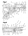
- An extinguishing device 1 is shown at an end portion 1 of a cantilever arm 3.
- the cantilever arm 3 is, for example, and not further shown, a part of a telescoping Knickarmauslegers pivotally mounted on an insert device about a vertical surface to a footprint 4 axis and about a horizontally extending axis raised and lowered via actuators and by means of a control device of the insert device is controllable.
- the extinguishing device 1 comprises a firing head 5 for firefighting with a launcher pipe 6 for the application of an extinguishing medium, as shown by arrows 7 hinted. For a fire fighting at a freely accessible fire site is feasible.
- the extinguishing device 1 has a penetrating device 8.
- the penetration device 8 comprises a lance-shaped penetrating tool 9, which is designed by means of a linear drive 10 for a penetration process of a wall structure 11, so as to prevent penetration of the penetrating tool 9 in an interior 12 sheathed by the wall structure 11, e.g. a means of transport, in particular an airframe 13 in an application to reach as quickly as possible.
- the penetration tool 9 is tubular for passage of the extinguishing medium and in a projecting end 14 with a nozzle head 15, whereby after penetration of the wall structure 11, a fire fighting operation by spraying the extinguishing medium in the interior 12 of the room cell 13 is feasible.
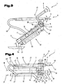
- the projector head 8 with the launcher 6 and the penetrating device 8 with the penetrating tool 9 are constructed according to the embodiment shown on a device carrier 16 which is arranged in the end region 2 of the cantilever arm 3.
- the device carrier 16 with the launcher head 5 and the penetrating device 8 is mounted on the cantilever arm 3 in a pivot bearing arrangement 19 about a lifting axis 17 approximately parallel to the contact surface 4, which extends approximately perpendicularly to a vertical elevation plane 18 approximately perpendicular to the contact surface 4.
- the pivoting movement about the lifting axis 17 is controlled, for example, by a lifting drive 20, by a double-acting pressure cylinder which can be charged with pressure medium, the pressure cylinder being articulated on the cantilever arm 3 on the one hand and on the device carrier 16 on the other hand.
- the launcher head 5 with the launcher pipe 6 is rotatable on the device carrier 16 in a pivot bearing arrangement 26 about a rotation axis 17 perpendicular to the axis of rotation 17 and by means of a rotary drive 28 - according to double arrow 29 - which aligns the ejection direction of the extinguishing medium - according to arrows 7 - to the respective fire can be, ie a longitudinal central axis 30 of the launcher tube 6 about the axis of rotation 27 is pivotable.
- a pivoting of the launcher pipe 6 is also in view of the use of penetrating device 8 also expedient, in principle, a rotation angle is not limited.
- the penetrating device 8 forms a pressurizable medium from a hydraulic system 34 acted upon, double-acting pressure cylinder 35 with a continuous tubular piston rod 36.
- the piston rod 36 is, as already described above, provided in the end 14 with the nozzle head 15, the lancet-shaped for penetrating the Wall structure 11 is formed.
- the pressure cylinder 35 forms the linear drive 10 for adjusting the Penetrierwerkmaschinees 9, so the piston rod 36 - according to double arrow 37 - from.
- a line 39, in particular a pressure hose 40 for the supply of the extinguishing medium from the conduit 32 is connected to the piston rod 36.
- a connection of the pressure hose 40 to the conduit 32 takes place with the interposition of a preferably feman tenubarem valve 41st
- the printing cylinder 35 is on the device carrier 16, preferably on a side surface 42 by means a support bracket 43 attached.
- An alignment of the longitudinal central axis 23 of the pressure cylinder 35 and thus of Penetrierwerkmaschinees 9 for optimizing the Penetriervorganges done by pivoting the device carrier 16 by means of the lifting drive 20 to the elevation plane 18 of the cantilever arm 3 perpendicular Hubachse 17, ie by the pivoting of the device carrier 16 to the lifting axis 17 is a common pivoting of the longitudinal central axis 23 of the Penetriertechnikmaschinegnees 9 and the longitudinal central axis 30 of the launcher tube 6 in the erectile plane 18 and a parallel thereto extending plane 44, regardless of the pitcher tube 6 about the axis of rotation 17 perpendicular to the axis of rotation 27 by means of Rotary drive 28 rotatable to rotate in a case of application of the penetrating device 8, the projector tube 6 in a position in which no collision with the penetrating tool 9
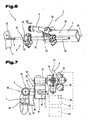
- a plate-shaped bracket 45 which projects beyond the erecting plane 18 of the extension arm 3, is arranged as the device support 16, which protrudes over a profile extension 46 into a hollow profile 47 forming the extension arm 3 and is rigidly secured.
- the plate-shaped bracket 45 supports at opposite side surfaces 48, 49 the launcher head 5 with the launcher pipe 6 and the penetrating device 8 with the pressure cylinder 35 with the hollow penetrating tool 9 formed as a piston rod 36.
- the launcher head 5 and the penetrating device 8 are each in bearing assemblies 50, 51, the lifting shaft 17 forming, which extends to the righting plane 18 at a right angle, pivotally mounted.
- Independent lifting drives 52, 53 ensure independent pivoting of the thrower head 5 and the penetrating device 8 for aligning their longitudinal central axes 23, 30 in the erecting plane 18 or in the plane 44 extending parallel thereto.
- a lifting drive 52 is in the illustrated embodiment, e.g. a at an underside 54 of the cantilever arm 3 e.g.
- a rotary drive 56 is also possible, e.g. a hydraulic motor, electr. Servo motor etc. directly in accordance with double arrows causes a stroke adjustment of the projector head 5 and / or the penetrating device 8 about the lifting axis 17.
- the pressure cylinder 55 is supported via a bearing block 57 relative to the boom arm 3 and is mounted on the piston rod side on a steering lever 59 of the thrower head 5 or the penetrating device 8.
- the launcher tube 6 is further, as already described above, rotatably mounted in the pivot bearing assembly 26 about the axis of rotation 17 perpendicular to the axis of rotation 27 and by means of the rotary drive 28 on the launcher head 5 - according to double arrow 29.
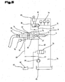
- FIG. 5 is a possible embodiment of the proposed for acting on the pressure cylinder 35 of the penetrating device 8 with the pressure medium hydraulic system 34 shown in a simplified hydraulic scheme.
- the pressure cylinder 35 forms the linear drive 10 for adjusting the Penetrierwerkmaschinees 9, which is part of the continuous piston rod 36 and between an extended position and a retracted position by appropriate loading of a piston 62 of the piston rod 36 from each other separate pressure chambers 63, 64 with the pressure medium From a tank 65.
- a pressure line 67 and a supply line 68 into the pressure chamber 64 for the retraction movement and a bypass line 68 into the pressure chamber 63 for the extension movement of the piston rod 36.
- the bypass line 68 connects the pressure line 67 directly to the pressure chamber 63 while preferably provided for the supply of the pressure chamber 64 in the supply line 68 remotely controllable control valve 70 is.
- the pressure chamber 63 is acted upon directly with the operating pressure while the pressure chamber 64 is acted upon by the control valve 70 optionally with the medium pressure. From the pressure chamber 64 outgoing leads a return line 71 via a still described in detail control and regulating device for the discharge of the medium in the tank 65th
- the penetrating tool 9 or the piston rod 36 is formed in the pressure chamber 63 causing the extension movement of the penetrating tool 9 with a diameter 72 which is greater than a diameter 73 in which the retraction movement causing pressure chamber 64, resulting in different Kolbenwirktlächen 74, 75 and This results in generally upon application of both pressure chambers 63, 64 with the same medium pressure, an adjustment of the Penetrierwerkmaschinees 9 in the retracted end position, which is limited by a piston stroke, by a the piston movement surface causing the extension movement resulting restoring force due to the area ratios of the piston effective surfaces 74, 75th
- control valve 70 is in a switching position, which establishes a line connection between the pump 66 and the pressure chamber 64, while the further pressure chamber 63 with the pressure medium supplying bypass line 69 forms a direct connection from the pump 66 to the pressure chamber 63.
- At least one pressure storage element 76 e.g. a bladder accumulator, piston accumulator, diaphragm accumulator, etc. arranged to have a large volume of the pressurized pressure medium without substantial line losses available for an extension movement of the Penetrierwerkmaschinemaschinees 9 directly to the pressure chamber 63 whereby a high acceleration and end speed of Penetrierwerkmaschinees 9 is achieved.
- a pressure storage element 76 e.g. a bladder accumulator, piston accumulator, diaphragm accumulator, etc.
- a further control valve 78 is arranged for optional pressure relief of the pressure chamber 63 for the extension movement opposite pressure chamber 64, from which the return line 71 into the tank 65 leads.
- the control valve 78 has a large flow cross-section in order to achieve a rapid expansion of the pressure chamber 64 and at least one further pressure accumulator element 79 is provided in addition to the flow connection to the return line 71 for a temporary storage of the medium. This prevents a braking effect during the extension movement of the penetrating tool 9, due to a flow resistance in the relatively long return line 71, and makes it possible to keep the dimension of the return line 71 low.
- the control valve 70 arranged in the supply line 68 between the pump 66 and the retraction movement 64 is switched to a blocking position and the control valve 78 at the outlet 77 of the pressure chamber 64 is moved to an open position and the pressure chamber causing the extension movement 63 on the one hand with the pressure medium from the immediately upstream accumulator element 76 plus the Medittmstroms the pump 66 acted upon.
- the pressure medium stored in the pressure storage element 79 at a high and the operating pressure corresponding pressure medium is achieved for a penetration high acceleration of the extension movement and a high end speed of the penetrating tool 9.
- the control valve 78 is preferably assigned a switching valve 80 for an opening operation against a spring arrangement 81 effecting a closed position.
- the reversal of the control valve 70 and the control valve 78 is remotely operable via a control means 82, e.g. on a control console 83 and a line connection for signal transmission, but also a wireless signal transmission for reversing the control valve 70 and the control valve 78 and the switching valve 80 is possible.
- the projector head 5 with the launcher tube 6 and the penetrating device 8, consisting of the pressure cylinder 35 with the Penetrierwerkmaschine 9 are arranged in the end region 2 of the boom 3 as an independent building modules.
- the projector head 5 is according to this embodiment on a side surface 84 of the extension arm 3 and the pressure cylinder 35 on an upper side 85 of the extension arm 3 each have a lifting drive 20, for example, the hydr. or electr.
- Rotary drive 56 to parallel to each other and at right angles to the righting plane 18 extending Hubachsen 86, 87 pivotally mounted.
- both the projector head 5 with the launcher tube 6 and the pressure cylinder 35 with the penetrating tool 9 in parallel to the Aufrichteebene 18 levels in a predetermined angle to a longitudinal center axis 88 of the cantilever arm 3 is pivotable.
- the launcher tube 6 is rotatable relative to the launcher head 5 by means of a further rotary drive 89 about an axis of rotation 90 perpendicular to the lifting axis 86.
- the supply of the extinguishing medium for the application with the launcher pipe 6 is performed by rotary distributor 91st
- a camera 92 is arranged in the end region 2 of the extension arm 3, preferably in a protected position within a hollow profile of the extension arm 3.
- the camera can be operated remotely, e.g. via signal and control lines or wirelessly via radio signal transmission both the camera settings as well as in their orientation to a desired field of view.
- a control and monitoring device 93 is, for example, as already described above integrated in the control console 83 which is provided in a command point not shown further or the control station of an emergency vehicle and includes, for example, the required control and communication means, monitor, etc.
- the penetration device 8 or the pressure cylinder 35 is equipped at a protruding end 94 with a detection device 95 with measuring and / or sensing means 96 with the control and monitoring device 93 for transmitting measurement signals relating to an angular orientation of Penetrierwerkmaschinees. 9 is communicatively connected to the wall structure 11 to be penetrated.
- This detection device 95 with the measuring and / or feeler means 96 can be based on a distance measurement with proximity sensors, laser measurement, ultrasound measurement, etc. and serves in conjunction with the lifting drive 20 for the penetrating device 8 for automatic positioning for an approximately rectangular orientation of the penetration tool. 9 on the cell structure.
- a light beam transmitter 97 and a light reflection receiver 98 are provided on the pressure cylinder 35, facing the wall structure 11, as the detection device 95, instead of the measuring and sensing means 96.
- a light beam is focused by means of the light beam transmitter on the wall structure 11 and determined by stroke adjustment about the lifting axis 87, the position by means of the light reflection receiver 98, the maximum light intensity in an evaluation switching module 99 is detected, which is then achieved when the impact angle is about 90 °.
- the penetration device 8 has, as the linear drive 10, for example, the pressure cylinder 35 which is provided with the continuous, hollow piston rod 36 and formed by the piston 62 separate pressure chambers 63, 64, which by respective application of the pressure medium for the adjustment of Piston rod - according to double arrow 37 - are designed.
- the piston rod 36 is provided with the designed as a nozzle head 15, frustoconical penetrating tool 9.
- the penetrating tool 9 is equipped with communication and or detection means 100, for example, a speaker 101, microphone 102 and the camera 92, in particular a equipped with a CCD chip lens 103 include.
- the penetrating tool 9 approximately radially introduced recordings 104 for a protected integration of the speaker 101 and microphone 102 is provided.
- the camera 92 and the lens 103 with the CCD chip, in a center bore 105 of a hollow tip 106 forming penetrating insert 107 is arranged and in this via a piston rod 36 in the longitudinal direction through protective tube 108, the secure passage of a Data line 109 or a light guide, etc. is used, by means of an arranged at the end 38 of the piston rod 36 adjustment 110 adjustable - according to double arrow 111 - stored.
- the camera 92 is adjustable during a penetrating operation with the penetration insert 107 in a retracted position and can be adjusted after the successful penetration into a functional position outside a ring cutting edge 112 of the penetrating insert 107 to create a comprehensive field of view.
- the penetration insert 107 is made of a high strength metal alloy, e.g. High speed steel, carbide, etc. formed to prevent deformation of the ring cutting edge 112 and to achieve an optimal penetration process.
- a high strength metal alloy e.g. High speed steel, carbide, etc. formed to prevent deformation of the ring cutting edge 112 and to achieve an optimal penetration process.
- the data line 109 or a light guide runs in the protective tube 108 extending approximately coaxially in the bore of the piston rod 36.
- Wires 115 for communication connection and power supply of the loudspeaker 101, microphone 102 and light source 113 are, for example, in one or more grooves 116, which are provided in the inner bore of the piston rod 36 and this protruding in the longitudinal direction inserted and protected, for example, with its potting compound in these grooves 116 arranged.
- the data line 109 of the camera 92 and the lines 115 are line-connected to the control and / or monitoring device 93 for evaluating the signals and implementing control measures for adjusting the penetrating device and also an energy source 117.
- the receptacles 104 which forms a depression in a surface 118 of the Penetrierwerkmaschinees 9 for a protected arrangement of the communication and / or detection means 100, at least one sensor 119, such as temperature measuring sensor, gas probe, etc. integrated, the likewise provided with, for example, in the control and / or monitoring device 93 evaluation circuit 120 is connected, whereby a deployment force further essential for an optimized use information are available, such as room temperature, air quality, gas contamination, gas concentration, etc.
- the camera 93 described in the embodiment shown is known both from the medical application but also from micromechanics and u. a. also the designation digital camera, video endoscope, etc. carries and the image taken from the lens is digitized by the integrated CCD chip and by means of a processor, the digital data in the following, for example, for output to a monitor and / or data storage, etc., directed.
- Such digital cameras are suitable wherever smallest dimensions for an inspection device are to be striven for.
Landscapes
- Health & Medical Sciences (AREA)
- Public Health (AREA)
- Business, Economics & Management (AREA)
- Emergency Management (AREA)
- Actuator (AREA)
- Nozzles (AREA)
- Manipulator (AREA)
- Operation Control Of Excavators (AREA)
- Fire-Extinguishing By Fire Departments, And Fire-Extinguishing Equipment And Control Thereof (AREA)
- Details Of Spanners, Wrenches, And Screw Drivers And Accessories (AREA)
Priority Applications (3)
| Application Number | Priority Date | Filing Date | Title |
|---|---|---|---|
| EP15187976.4A EP3028746B1 (de) | 2007-04-12 | 2008-03-26 | Einsatzvorrichtung zur brandbekämpfung |
| EP16157141.9A EP3045210A1 (de) | 2007-04-12 | 2008-03-26 | Einsatzvorrichtung zur brandbekämpfung |
| EP11185299.2A EP2420293B1 (de) | 2007-04-12 | 2008-03-26 | Penetriervorrichtung zur Brandbekämpfung |
Applications Claiming Priority (1)
| Application Number | Priority Date | Filing Date | Title |
|---|---|---|---|
| AT0056407A AT505111B1 (de) | 2007-04-12 | 2007-04-12 | Einsatzvorrichtung zur brandbekämpfung |
Related Child Applications (4)
| Application Number | Title | Priority Date | Filing Date |
|---|---|---|---|
| EP11185299.2A Division EP2420293B1 (de) | 2007-04-12 | 2008-03-26 | Penetriervorrichtung zur Brandbekämpfung |
| EP16157141.9A Division EP3045210A1 (de) | 2007-04-12 | 2008-03-26 | Einsatzvorrichtung zur brandbekämpfung |
| EP15187976.4A Division EP3028746B1 (de) | 2007-04-12 | 2008-03-26 | Einsatzvorrichtung zur brandbekämpfung |
| EP11185299.2 Division-Into | 2011-10-14 |
Publications (3)
| Publication Number | Publication Date |
|---|---|
| EP1980294A2 EP1980294A2 (de) | 2008-10-15 |
| EP1980294A3 EP1980294A3 (de) | 2008-12-17 |
| EP1980294B1 true EP1980294B1 (de) | 2013-07-17 |
Family
ID=39638960
Family Applications (4)
| Application Number | Title | Priority Date | Filing Date |
|---|---|---|---|
| EP08005564.3A Active EP1980294B1 (de) | 2007-04-12 | 2008-03-26 | Einsatzvorrichtung zur Brandbekämpfung |
| EP16157141.9A Withdrawn EP3045210A1 (de) | 2007-04-12 | 2008-03-26 | Einsatzvorrichtung zur brandbekämpfung |
| EP11185299.2A Active EP2420293B1 (de) | 2007-04-12 | 2008-03-26 | Penetriervorrichtung zur Brandbekämpfung |
| EP15187976.4A Active EP3028746B1 (de) | 2007-04-12 | 2008-03-26 | Einsatzvorrichtung zur brandbekämpfung |
Family Applications After (3)
| Application Number | Title | Priority Date | Filing Date |
|---|---|---|---|
| EP16157141.9A Withdrawn EP3045210A1 (de) | 2007-04-12 | 2008-03-26 | Einsatzvorrichtung zur brandbekämpfung |
| EP11185299.2A Active EP2420293B1 (de) | 2007-04-12 | 2008-03-26 | Penetriervorrichtung zur Brandbekämpfung |
| EP15187976.4A Active EP3028746B1 (de) | 2007-04-12 | 2008-03-26 | Einsatzvorrichtung zur brandbekämpfung |
Country Status (9)
| Country | Link |
|---|---|
| US (2) | US9061168B2 (pl) |
| EP (4) | EP1980294B1 (pl) |
| CN (1) | CN101678223B (pl) |
| AT (1) | AT505111B1 (pl) |
| CA (1) | CA2684203C (pl) |
| ES (2) | ES2431336T3 (pl) |
| PL (2) | PL3028746T3 (pl) |
| RU (1) | RU2458717C2 (pl) |
| WO (1) | WO2008124861A2 (pl) |
Cited By (2)
| Publication number | Priority date | Publication date | Assignee | Title |
|---|---|---|---|---|
| EP3192569A1 (de) | 2016-01-15 | 2017-07-19 | Albert Ziegler GmbH | Durchstossvorrichtung zum durchstossen einer wandstruktur |
| EP4620537A1 (de) | 2024-03-20 | 2025-09-24 | Albert Ziegler GmbH | Durchstossvorrichtung zum durchstossen einer wandstruktur |
Families Citing this family (43)
| Publication number | Priority date | Publication date | Assignee | Title |
|---|---|---|---|---|
| CN101766876B (zh) * | 2010-02-09 | 2013-01-09 | 沈阳捷通消防车有限公司 | 带有双上臂结构的消防车 |
| WO2011133230A2 (en) * | 2011-07-25 | 2011-10-27 | Alan Berberick | High-rise building fire fighting portable shaft system |
| JP5681748B2 (ja) * | 2012-04-30 | 2015-03-11 | ソウル特別市 | 消火装置 |
| DE202012011517U1 (de) | 2012-11-30 | 2013-12-05 | Wolfgang Krumm | Penetriervorrichtung mit Steuerkolben |
| DE102012023458A1 (de) | 2012-11-30 | 2014-06-18 | Wolfgang Krumm | Penetriervorrichtung mit Steuerkolben |
| CN103212178B (zh) * | 2013-03-19 | 2016-06-22 | 丹纳森工程装备(杭州)有限公司 | 一种高速穿墙细水雾灭火方法 |
| CN103611227B (zh) * | 2013-07-30 | 2015-12-09 | 陈苏 | 钻洞穿墙灭火装置 |
| EP2923738B1 (en) | 2014-03-28 | 2017-01-25 | Iveco Magirus Ag | Penetration device for use in fire-fighting operations, in particular in the context of airport rescue |
| US9682261B1 (en) | 2014-05-07 | 2017-06-20 | Tristan Y. Saito | Piercing nozzle |
| CN106669061A (zh) * | 2015-11-09 | 2017-05-17 | 中国人民解放军军械工程学院 | 伸缩式灭火枪 |
| CN105288911B (zh) * | 2015-12-02 | 2021-06-15 | 威海广泰空港设备股份有限公司 | 带有穿刺功能的举高消防车上车结构 |
| CN105251166B (zh) * | 2015-12-02 | 2021-06-22 | 威海广泰空港设备股份有限公司 | 消防炮炮身结构 |
| EP3541480B1 (en) | 2016-11-16 | 2025-01-01 | Viking Life-Saving Equipment A/S | Fire fighting device |
| US10286239B2 (en) * | 2017-02-08 | 2019-05-14 | Oshkosh Corporation | Fire apparatus piercing tip ranging and alignment system |
| CN106890415A (zh) * | 2017-04-28 | 2017-06-27 | 三汽车制造有限公司 | 消防车 |
| DE102017208032A1 (de) * | 2017-05-12 | 2018-11-15 | Putzmeister Engineering Gmbh | Verteilermast für mobile Betonpumpen mit Gelenken für nebeneinanderliegende Arme und mobile Betonpumpe |
| US10610715B1 (en) * | 2018-05-21 | 2020-04-07 | Michael Taylor | Barrier piercing firehouse nozzle assemblies |
| RU189618U1 (ru) * | 2019-02-22 | 2019-05-29 | Константин Васильевич Смирнов | Пожарный переносной ствол |
| AT522084B1 (de) | 2019-04-11 | 2020-08-15 | Avl List Gmbh | Löschvorrichtung |
| RU192151U1 (ru) * | 2019-05-19 | 2019-09-05 | Константин Васильевич Смирнов | Пожарный переносной ствол. |
| RU196191U1 (ru) * | 2019-09-05 | 2020-02-19 | Константин Васильевич Смирнов | Пожарный переносной ствол |
| US20210146175A1 (en) * | 2019-11-19 | 2021-05-20 | They | Fire Suppression Device and System |
| CN110975190B (zh) * | 2019-12-21 | 2021-04-13 | 江西达普利装饰设计工程有限公司 | 一种保护气膜建筑底部膜的消防喷淋装置 |
| AT523484B1 (de) * | 2020-01-22 | 2023-06-15 | Rosenbauer Int Ag | Verfahren und Penetriereinheit zum Einbringen eines Fluides in eine Batterie sowie damit ausgestattetes Fahrzeug |
| CN112546490A (zh) * | 2020-11-30 | 2021-03-26 | 长沙中联消防机械有限公司 | 应急灭火系统和消防设备 |
| CN112642080B (zh) * | 2020-12-24 | 2022-08-12 | 广东宿卫保安服务有限公司 | 一种消防救援机器人 |
| WO2022169464A1 (en) * | 2021-02-08 | 2022-08-11 | They | Fire suppression device and system |
| CN113082584A (zh) * | 2021-05-25 | 2021-07-09 | 广东泓锐消防技术服务有限公司 | 一种用于建筑室内消防的自动喷水系统 |
| AT524843B1 (de) * | 2021-06-16 | 2022-10-15 | Avl List Gmbh | Löschlanze |
| AT525039B1 (de) | 2021-06-16 | 2022-12-15 | Avl List Gmbh | Wagen zur brandbekämpfung |
| WO2023277700A1 (en) * | 2021-07-02 | 2023-01-05 | Firespear Protection Systems As | Fire extinguishing assembly |
| AT525521B1 (de) | 2021-09-29 | 2024-02-15 | Avl List Gmbh | Tisch zum manipulieren |
| AT525274B1 (de) * | 2021-10-14 | 2023-02-15 | Avl List Gmbh | Löschlanze mit längenverstellbarer festlegeeinrichtung |
| CN114040070A (zh) * | 2021-11-08 | 2022-02-11 | 江西合力泰科技有限公司 | 一种双摄模组的喷胶方法 |
| CN115122303B (zh) * | 2022-05-13 | 2024-04-19 | 泰州市鸿宝消防器材有限公司 | 一种消防用机械外骨骼组件 |
| CN115228028B (zh) * | 2022-06-14 | 2023-08-25 | 河南理工大学 | 一种便携式抑燃抑爆消防枪及其方法 |
| CN115228020B (zh) * | 2022-07-07 | 2023-07-25 | 浙江中辰城市应急服务管理有限公司 | 一种快速降温的便携式消防水炮 |
| DE102022120986A1 (de) | 2022-08-19 | 2024-02-22 | Audi Aktiengesellschaft | Löschlanzenvorrichtung und Verfahren zum Durchstoßen einer Batteriewandung einer Batterie |
| CN116036528A (zh) * | 2023-02-22 | 2023-05-02 | 南京航空航天大学 | 一种消防救援的多任务机械臂 |
| PL444622A1 (pl) | 2023-04-26 | 2024-01-03 | Politechnika Śląska | Urządzenie do gaszenia i chłodzenia baterii samochodów z napędem elektrycznym |
| CN116549882A (zh) * | 2023-05-22 | 2023-08-08 | 海天消防科技股份有限公司 | 一种仓库易燃物堆积应急灭火装置 |
| CN117357836A (zh) * | 2023-08-31 | 2024-01-09 | 湖南中联重科应急装备有限公司 | 消防机械及其控制方法 |
| CN117159960A (zh) * | 2023-09-27 | 2023-12-05 | 北京中卓时代消防装备科技有限公司 | 一种消防车的穿刺针的控制方法、控制装置和消防车 |
Family Cites Families (23)
| Publication number | Priority date | Publication date | Assignee | Title |
|---|---|---|---|---|
| US2547334A (en) * | 1947-10-21 | 1951-04-03 | Cardox Corp | Fire-extinguishing apparatus |
| SU860777A1 (ru) * | 1979-12-14 | 1981-09-07 | Государственный Ордена Трудового Красного Знамени Научно-Исследовательский Институт Гражданской Авиации | Пожарный ствол-пробойник |
| US4742220A (en) * | 1984-09-20 | 1988-05-03 | Skan-A-Matic Corp. | System for optical scanning over a large depth of field and obtaining high resolution of bar codes |
| US4708088A (en) * | 1985-02-22 | 1987-11-24 | Gene Purvis | Spraying method and apparatus |
| SU1718983A1 (ru) * | 1988-04-04 | 1992-03-15 | Государственный научно-исследовательский институт гражданской авиации | Пожарный ствол |
| SE464533B (sv) * | 1989-09-01 | 1991-05-06 | Kamyr Ab | Anordning foer mottagande och efterfoeljande uttoemning av hydraulvaetska ur hydraulsystem |
| US5211245A (en) * | 1991-07-01 | 1993-05-18 | Crash Rescue Equipment Service, Inc. | Vehicle mounted aerial lift |
| SE510351C2 (sv) * | 1995-12-29 | 1999-05-17 | Kvaerner Pulping Tech | Hydraulaggregat |
| US5839664A (en) | 1996-07-31 | 1998-11-24 | Crash Rescue Equipment Service, Inc, | Fluid discharge nozzle assembly |
| SE509895C2 (sv) * | 1997-08-15 | 1999-03-22 | Cold Cut Systems Svenska Ab | Metod och utrustning i räddningstjänstverksamhet |
| US6130437A (en) * | 1998-04-24 | 2000-10-10 | Hama Sensors, Inc. | Sensor and detection system having wide diverging beam optics |
| JP3549017B2 (ja) | 2000-07-21 | 2004-08-04 | 松下電器産業株式会社 | フリップチップ実装方法 |
| US6446731B1 (en) * | 2000-12-20 | 2002-09-10 | Joseph J. Soroski | Smoke evacuating fire vehicle |
| CN2487398Y (zh) | 2001-07-20 | 2002-04-24 | 徐州重型机械厂 | 高喷车救援破碎装置 |
| FI113623B (fi) * | 2002-06-03 | 2004-05-31 | Bronto Skylift Oy Ab | Järjestely palonsammutukseen |
| DE10227966A1 (de) * | 2002-06-22 | 2004-01-08 | Deere & Company, Moline | Hydraulische Steueranordnung für eine mobile Arbeitsmaschine |
| US7055613B1 (en) * | 2003-03-12 | 2006-06-06 | Schwing America, Inc. | Self leveling boom system with rotatable working assembly |
| DE10337601A1 (de) * | 2003-08-16 | 2005-03-10 | Deere & Co | Hydropneumatische Federungseinrichtung |
| DE102004039973B4 (de) * | 2003-08-25 | 2017-02-02 | Iav Gmbh Ingenieurgesellschaft Auto Und Verkehr | Aktive Fahrwerkaufhängung für Fahrzeuge |
| DE102004012362A1 (de) * | 2004-03-13 | 2005-09-22 | Deere & Company, Moline | Hydraulische Anordnung |
| US7530403B2 (en) * | 2004-04-05 | 2009-05-12 | City Of Hialeah | Transport pumper |
| US7611075B2 (en) * | 2005-08-10 | 2009-11-03 | Relyea Robert G | Extensible aerial boom having two independently operated fluid nozzles |
| US7438239B2 (en) * | 2005-09-19 | 2008-10-21 | The Southern Company | Fire fighting piercing nozzle device |
-
2007
- 2007-04-12 AT AT0056407A patent/AT505111B1/de active
-
2008
- 2008-03-26 EP EP08005564.3A patent/EP1980294B1/de active Active
- 2008-03-26 EP EP16157141.9A patent/EP3045210A1/de not_active Withdrawn
- 2008-03-26 ES ES08005564T patent/ES2431336T3/es active Active
- 2008-03-26 PL PL15187976T patent/PL3028746T3/pl unknown
- 2008-03-26 ES ES11185299.2T patent/ES2583263T3/es active Active
- 2008-03-26 EP EP11185299.2A patent/EP2420293B1/de active Active
- 2008-03-26 EP EP15187976.4A patent/EP3028746B1/de active Active
- 2008-03-26 PL PL11185299.2T patent/PL2420293T4/pl unknown
- 2008-04-14 CA CA2684203A patent/CA2684203C/en active Active
- 2008-04-14 CN CN2008800186338A patent/CN101678223B/zh not_active Expired - Fee Related
- 2008-04-14 WO PCT/AT2008/000137 patent/WO2008124861A2/de not_active Ceased
- 2008-04-14 RU RU2009141720/12A patent/RU2458717C2/ru active
- 2008-04-14 US US12/450,749 patent/US9061168B2/en active Active
-
2015
- 2015-05-15 US US14/712,967 patent/US9480868B2/en active Active
Cited By (3)
| Publication number | Priority date | Publication date | Assignee | Title |
|---|---|---|---|---|
| EP3192569A1 (de) | 2016-01-15 | 2017-07-19 | Albert Ziegler GmbH | Durchstossvorrichtung zum durchstossen einer wandstruktur |
| DE102016200468A1 (de) | 2016-01-15 | 2017-07-20 | Albert Ziegler Gmbh | Durchstoßvorrichtung zum Durchstoßen einer Wandstruktur |
| EP4620537A1 (de) | 2024-03-20 | 2025-09-24 | Albert Ziegler GmbH | Durchstossvorrichtung zum durchstossen einer wandstruktur |
Also Published As
| Publication number | Publication date |
|---|---|
| US9480868B2 (en) | 2016-11-01 |
| RU2009141720A (ru) | 2011-05-20 |
| US20150246251A1 (en) | 2015-09-03 |
| WO2008124861A2 (de) | 2008-10-23 |
| EP2420293B1 (de) | 2016-03-23 |
| AT505111A1 (de) | 2008-10-15 |
| ES2431336T3 (es) | 2013-11-26 |
| PL2420293T3 (pl) | 2016-12-30 |
| EP2420293A1 (de) | 2012-02-22 |
| WO2008124861A3 (de) | 2008-12-18 |
| EP3045210A1 (de) | 2016-07-20 |
| CN101678223B (zh) | 2012-02-01 |
| CA2684203C (en) | 2016-05-24 |
| RU2458717C2 (ru) | 2012-08-20 |
| US9061168B2 (en) | 2015-06-23 |
| US20100044059A1 (en) | 2010-02-25 |
| EP3028746B1 (de) | 2017-03-01 |
| ES2583263T3 (es) | 2016-09-20 |
| CA2684203A1 (en) | 2008-10-23 |
| CN101678223A (zh) | 2010-03-24 |
| AT505111B1 (de) | 2009-05-15 |
| EP1980294A3 (de) | 2008-12-17 |
| PL3028746T3 (pl) | 2017-08-31 |
| EP1980294A2 (de) | 2008-10-15 |
| EP3028746A1 (de) | 2016-06-08 |
| PL2420293T4 (pl) | 2016-12-30 |
Similar Documents
| Publication | Publication Date | Title |
|---|---|---|
| EP1980294B1 (de) | Einsatzvorrichtung zur Brandbekämpfung | |
| DE4313719C2 (de) | Transportvorrichtung | |
| WO2003026853A2 (de) | Vakuumhandhabungsvorrichtung | |
| EP3743574B1 (de) | Grossmanipulator mit endschlauchhalter | |
| EP3056083B1 (de) | Landwirtschaftliche feldspritze | |
| DE10308366B3 (de) | Schnorchelvorrichtung für ein U-Boot | |
| DE1580769C3 (de) | Anordung zum Waschen von Fahrzeugen in Fahrzeugwaschanlage n | |
| EP3192569B1 (de) | Durchstossvorrichtung zum durchstossen einer wandstruktur | |
| DE102017104814A1 (de) | Steuer- und/oder Regelsystem, landwirtschaftliches Nutzfahrzeug und Verfahren zur Steuerung und/oder Regelung eines landwirtschaftlichen Nutzfahrzeugs | |
| EP4620537A1 (de) | Durchstossvorrichtung zum durchstossen einer wandstruktur | |
| WO2019025326A2 (de) | Funktionseinheit für einen bearbeitungskopf, bearbeitungskopf und funktionselement | |
| DE102013206696B4 (de) | Vorrichtung und ein Verfahren zur Steuerung einer Handhabungseinrichtung | |
| WO2016146106A1 (de) | Stützvorrichtung, fahrzeug und verfahren zur abstützung eines fahrzeugs | |
| EP3305071A1 (de) | Steuersystem, landwirtschaftliches nutzfahrzeug und verfahren zur steuerung eines landwirtschaftlichen nutzfahrzeugs | |
| DE202007000505U1 (de) | Robotertaugliche Bearbeitungseinrichtung | |
| EP0913295A1 (de) | Fahrzeug zum Aufnehmen und transportieren von Lasten | |
| EP4624343A1 (de) | Haltevorrichtung zum anbringen einer sprühdüse an einem unbemannten luftfahrzeug | |
| DE102018126523B4 (de) | Arbeitsmaschine, insbesondere Radlader zum Holzumschlag | |
| WO2000079061A1 (de) | Verstelleinrichtung für eine räumvorrichtung, insbesondere räumschild für schneeräumung | |
| DE102010012532A1 (de) | Vorrichtung zum Laserschweißen | |
| DE102005045153A1 (de) | Transportvorrichtung | |
| DE4112820A1 (de) | Vorrichtung zum loeschen von oelbraenden an bohrloechern oder oelleitungen | |
| DE7218797U (de) | Hydraulikzylinder zum kippen von fahrerhaeusern | |
| DE757365A (pl) |
Legal Events
| Date | Code | Title | Description |
|---|---|---|---|
| PUAI | Public reference made under article 153(3) epc to a published international application that has entered the european phase |
Free format text: ORIGINAL CODE: 0009012 |
|
| AK | Designated contracting states |
Kind code of ref document: A2 Designated state(s): AT BE BG CH CY CZ DE DK EE ES FI FR GB GR HR HU IE IS IT LI LT LU LV MC MT NL NO PL PT RO SE SI SK TR |
|
| AX | Request for extension of the european patent |
Extension state: AL BA MK RS |
|
| PUAL | Search report despatched |
Free format text: ORIGINAL CODE: 0009013 |
|
| AK | Designated contracting states |
Kind code of ref document: A3 Designated state(s): AT BE BG CH CY CZ DE DK EE ES FI FR GB GR HR HU IE IS IT LI LT LU LV MC MT NL NO PL PT RO SE SI SK TR |
|
| AX | Request for extension of the european patent |
Extension state: AL BA MK RS |
|
| 17P | Request for examination filed |
Effective date: 20090522 |
|
| AKX | Designation fees paid |
Designated state(s): AT BE BG CH CY CZ DE DK EE ES FI FR GB GR HR HU IE IS IT LI LT LU LV MC MT NL NO PL PT RO SE SI SK TR |
|
| 17Q | First examination report despatched |
Effective date: 20091007 |
|
| GRAP | Despatch of communication of intention to grant a patent |
Free format text: ORIGINAL CODE: EPIDOSNIGR1 |
|
| GRAP | Despatch of communication of intention to grant a patent |
Free format text: ORIGINAL CODE: EPIDOSNIGR1 |
|
| GRAS | Grant fee paid |
Free format text: ORIGINAL CODE: EPIDOSNIGR3 |
|
| GRAA | (expected) grant |
Free format text: ORIGINAL CODE: 0009210 |
|
| AK | Designated contracting states |
Kind code of ref document: B1 Designated state(s): AT BE BG CH CY CZ DE DK EE ES FI FR GB GR HR HU IE IS IT LI LT LU LV MC MT NL NO PL PT RO SE SI SK TR |
|
| REG | Reference to a national code |
Ref country code: GB Ref legal event code: FG4D Free format text: NOT ENGLISH |
|
| REG | Reference to a national code |
Ref country code: CH Ref legal event code: EP |
|
| REG | Reference to a national code |
Ref country code: IE Ref legal event code: FG4D Free format text: LANGUAGE OF EP DOCUMENT: GERMAN |
|
| REG | Reference to a national code |
Ref country code: AT Ref legal event code: REF Ref document number: 621789 Country of ref document: AT Kind code of ref document: T Effective date: 20130815 |
|
| REG | Reference to a national code |
Ref country code: DE Ref legal event code: R096 Ref document number: 502008010300 Country of ref document: DE Effective date: 20130912 |
|
| REG | Reference to a national code |
Ref country code: ES Ref legal event code: FG2A Ref document number: 2431336 Country of ref document: ES Kind code of ref document: T3 Effective date: 20131126 |
|
| REG | Reference to a national code |
Ref country code: NL Ref legal event code: VDEP Effective date: 20130717 |
|
| REG | Reference to a national code |
Ref country code: LT Ref legal event code: MG4D |
|
| PG25 | Lapsed in a contracting state [announced via postgrant information from national office to epo] |
Ref country code: PT Free format text: LAPSE BECAUSE OF FAILURE TO SUBMIT A TRANSLATION OF THE DESCRIPTION OR TO PAY THE FEE WITHIN THE PRESCRIBED TIME-LIMIT Effective date: 20131118 Ref country code: NO Free format text: LAPSE BECAUSE OF FAILURE TO SUBMIT A TRANSLATION OF THE DESCRIPTION OR TO PAY THE FEE WITHIN THE PRESCRIBED TIME-LIMIT Effective date: 20131017 Ref country code: HR Free format text: LAPSE BECAUSE OF FAILURE TO SUBMIT A TRANSLATION OF THE DESCRIPTION OR TO PAY THE FEE WITHIN THE PRESCRIBED TIME-LIMIT Effective date: 20130717 Ref country code: LT Free format text: LAPSE BECAUSE OF FAILURE TO SUBMIT A TRANSLATION OF THE DESCRIPTION OR TO PAY THE FEE WITHIN THE PRESCRIBED TIME-LIMIT Effective date: 20130717 Ref country code: IS Free format text: LAPSE BECAUSE OF FAILURE TO SUBMIT A TRANSLATION OF THE DESCRIPTION OR TO PAY THE FEE WITHIN THE PRESCRIBED TIME-LIMIT Effective date: 20131117 Ref country code: CY Free format text: LAPSE BECAUSE OF FAILURE TO SUBMIT A TRANSLATION OF THE DESCRIPTION OR TO PAY THE FEE WITHIN THE PRESCRIBED TIME-LIMIT Effective date: 20130626 Ref country code: SE Free format text: LAPSE BECAUSE OF FAILURE TO SUBMIT A TRANSLATION OF THE DESCRIPTION OR TO PAY THE FEE WITHIN THE PRESCRIBED TIME-LIMIT Effective date: 20130717 |
|
| PG25 | Lapsed in a contracting state [announced via postgrant information from national office to epo] |
Ref country code: GR Free format text: LAPSE BECAUSE OF FAILURE TO SUBMIT A TRANSLATION OF THE DESCRIPTION OR TO PAY THE FEE WITHIN THE PRESCRIBED TIME-LIMIT Effective date: 20131018 Ref country code: SI Free format text: LAPSE BECAUSE OF FAILURE TO SUBMIT A TRANSLATION OF THE DESCRIPTION OR TO PAY THE FEE WITHIN THE PRESCRIBED TIME-LIMIT Effective date: 20130717 Ref country code: PL Free format text: LAPSE BECAUSE OF FAILURE TO SUBMIT A TRANSLATION OF THE DESCRIPTION OR TO PAY THE FEE WITHIN THE PRESCRIBED TIME-LIMIT Effective date: 20130717 Ref country code: LV Free format text: LAPSE BECAUSE OF FAILURE TO SUBMIT A TRANSLATION OF THE DESCRIPTION OR TO PAY THE FEE WITHIN THE PRESCRIBED TIME-LIMIT Effective date: 20130717 Ref country code: NL Free format text: LAPSE BECAUSE OF FAILURE TO SUBMIT A TRANSLATION OF THE DESCRIPTION OR TO PAY THE FEE WITHIN THE PRESCRIBED TIME-LIMIT Effective date: 20130717 |
|
| PG25 | Lapsed in a contracting state [announced via postgrant information from national office to epo] |
Ref country code: CY Free format text: LAPSE BECAUSE OF FAILURE TO SUBMIT A TRANSLATION OF THE DESCRIPTION OR TO PAY THE FEE WITHIN THE PRESCRIBED TIME-LIMIT Effective date: 20130717 |
|
| PG25 | Lapsed in a contracting state [announced via postgrant information from national office to epo] |
Ref country code: DK Free format text: LAPSE BECAUSE OF FAILURE TO SUBMIT A TRANSLATION OF THE DESCRIPTION OR TO PAY THE FEE WITHIN THE PRESCRIBED TIME-LIMIT Effective date: 20130717 Ref country code: EE Free format text: LAPSE BECAUSE OF FAILURE TO SUBMIT A TRANSLATION OF THE DESCRIPTION OR TO PAY THE FEE WITHIN THE PRESCRIBED TIME-LIMIT Effective date: 20130717 Ref country code: SK Free format text: LAPSE BECAUSE OF FAILURE TO SUBMIT A TRANSLATION OF THE DESCRIPTION OR TO PAY THE FEE WITHIN THE PRESCRIBED TIME-LIMIT Effective date: 20130717 Ref country code: RO Free format text: LAPSE BECAUSE OF FAILURE TO SUBMIT A TRANSLATION OF THE DESCRIPTION OR TO PAY THE FEE WITHIN THE PRESCRIBED TIME-LIMIT Effective date: 20130717 Ref country code: CZ Free format text: LAPSE BECAUSE OF FAILURE TO SUBMIT A TRANSLATION OF THE DESCRIPTION OR TO PAY THE FEE WITHIN THE PRESCRIBED TIME-LIMIT Effective date: 20130717 |
|
| PLBE | No opposition filed within time limit |
Free format text: ORIGINAL CODE: 0009261 |
|
| STAA | Information on the status of an ep patent application or granted ep patent |
Free format text: STATUS: NO OPPOSITION FILED WITHIN TIME LIMIT |
|
| PG25 | Lapsed in a contracting state [announced via postgrant information from national office to epo] |
Ref country code: IT Free format text: LAPSE BECAUSE OF FAILURE TO SUBMIT A TRANSLATION OF THE DESCRIPTION OR TO PAY THE FEE WITHIN THE PRESCRIBED TIME-LIMIT Effective date: 20130717 |
|
| 26N | No opposition filed |
Effective date: 20140422 |
|
| REG | Reference to a national code |
Ref country code: DE Ref legal event code: R097 Ref document number: 502008010300 Country of ref document: DE Effective date: 20140422 |
|
| PG25 | Lapsed in a contracting state [announced via postgrant information from national office to epo] |
Ref country code: LU Free format text: LAPSE BECAUSE OF FAILURE TO SUBMIT A TRANSLATION OF THE DESCRIPTION OR TO PAY THE FEE WITHIN THE PRESCRIBED TIME-LIMIT Effective date: 20140326 |
|
| REG | Reference to a national code |
Ref country code: CH Ref legal event code: PL |
|
| GBPC | Gb: european patent ceased through non-payment of renewal fee |
Effective date: 20140326 |
|
| REG | Reference to a national code |
Ref country code: IE Ref legal event code: MM4A |
|
| PG25 | Lapsed in a contracting state [announced via postgrant information from national office to epo] |
Ref country code: GB Free format text: LAPSE BECAUSE OF NON-PAYMENT OF DUE FEES Effective date: 20140326 Ref country code: LI Free format text: LAPSE BECAUSE OF NON-PAYMENT OF DUE FEES Effective date: 20140331 Ref country code: IE Free format text: LAPSE BECAUSE OF NON-PAYMENT OF DUE FEES Effective date: 20140326 Ref country code: CH Free format text: LAPSE BECAUSE OF NON-PAYMENT OF DUE FEES Effective date: 20140331 |
|
| REG | Reference to a national code |
Ref country code: AT Ref legal event code: MM01 Ref document number: 621789 Country of ref document: AT Kind code of ref document: T Effective date: 20140326 |
|
| PG25 | Lapsed in a contracting state [announced via postgrant information from national office to epo] |
Ref country code: AT Free format text: LAPSE BECAUSE OF NON-PAYMENT OF DUE FEES Effective date: 20140326 |
|
| PG25 | Lapsed in a contracting state [announced via postgrant information from national office to epo] |
Ref country code: MT Free format text: LAPSE BECAUSE OF FAILURE TO SUBMIT A TRANSLATION OF THE DESCRIPTION OR TO PAY THE FEE WITHIN THE PRESCRIBED TIME-LIMIT Effective date: 20130717 |
|
| REG | Reference to a national code |
Ref country code: FR Ref legal event code: PLFP Year of fee payment: 9 |
|
| PG25 | Lapsed in a contracting state [announced via postgrant information from national office to epo] |
Ref country code: BG Free format text: LAPSE BECAUSE OF FAILURE TO SUBMIT A TRANSLATION OF THE DESCRIPTION OR TO PAY THE FEE WITHIN THE PRESCRIBED TIME-LIMIT Effective date: 20130717 Ref country code: MC Free format text: LAPSE BECAUSE OF FAILURE TO SUBMIT A TRANSLATION OF THE DESCRIPTION OR TO PAY THE FEE WITHIN THE PRESCRIBED TIME-LIMIT Effective date: 20130717 |
|
| PG25 | Lapsed in a contracting state [announced via postgrant information from national office to epo] |
Ref country code: BE Free format text: LAPSE BECAUSE OF FAILURE TO SUBMIT A TRANSLATION OF THE DESCRIPTION OR TO PAY THE FEE WITHIN THE PRESCRIBED TIME-LIMIT Effective date: 20140331 Ref country code: TR Free format text: LAPSE BECAUSE OF FAILURE TO SUBMIT A TRANSLATION OF THE DESCRIPTION OR TO PAY THE FEE WITHIN THE PRESCRIBED TIME-LIMIT Effective date: 20130717 Ref country code: HU Free format text: LAPSE BECAUSE OF FAILURE TO SUBMIT A TRANSLATION OF THE DESCRIPTION OR TO PAY THE FEE WITHIN THE PRESCRIBED TIME-LIMIT; INVALID AB INITIO Effective date: 20080326 |
|
| REG | Reference to a national code |
Ref country code: FR Ref legal event code: PLFP Year of fee payment: 10 |
|
| REG | Reference to a national code |
Ref country code: FR Ref legal event code: PLFP Year of fee payment: 11 |
|
| REG | Reference to a national code |
Ref country code: DE Ref legal event code: R082 Ref document number: 502008010300 Country of ref document: DE Representative=s name: ABP BURGER RECHTSANWALTSGESELLSCHAFT MBH, DE |
|
| PGFP | Annual fee paid to national office [announced via postgrant information from national office to epo] |
Ref country code: FI Payment date: 20220309 Year of fee payment: 15 |
|
| PGFP | Annual fee paid to national office [announced via postgrant information from national office to epo] |
Ref country code: FR Payment date: 20220228 Year of fee payment: 15 |
|
| PGFP | Annual fee paid to national office [announced via postgrant information from national office to epo] |
Ref country code: ES Payment date: 20220405 Year of fee payment: 15 |
|
| PG25 | Lapsed in a contracting state [announced via postgrant information from national office to epo] |
Ref country code: FI Free format text: LAPSE BECAUSE OF NON-PAYMENT OF DUE FEES Effective date: 20230326 |
|
| PG25 | Lapsed in a contracting state [announced via postgrant information from national office to epo] |
Ref country code: FR Free format text: LAPSE BECAUSE OF NON-PAYMENT OF DUE FEES Effective date: 20230331 |
|
| REG | Reference to a national code |
Ref country code: ES Ref legal event code: FD2A Effective date: 20240506 |
|
| PG25 | Lapsed in a contracting state [announced via postgrant information from national office to epo] |
Ref country code: ES Free format text: LAPSE BECAUSE OF NON-PAYMENT OF DUE FEES Effective date: 20230327 |
|
| PG25 | Lapsed in a contracting state [announced via postgrant information from national office to epo] |
Ref country code: ES Free format text: LAPSE BECAUSE OF NON-PAYMENT OF DUE FEES Effective date: 20230327 |
|
| PGFP | Annual fee paid to national office [announced via postgrant information from national office to epo] |
Ref country code: DE Payment date: 20260320 Year of fee payment: 19 |