EP1979548B1 - Verfahren zur federung einer bewegung eines einsatzes einer arbeitsmaschine - Google Patents
Verfahren zur federung einer bewegung eines einsatzes einer arbeitsmaschine Download PDFInfo
- Publication number
- EP1979548B1 EP1979548B1 EP07701123A EP07701123A EP1979548B1 EP 1979548 B1 EP1979548 B1 EP 1979548B1 EP 07701123 A EP07701123 A EP 07701123A EP 07701123 A EP07701123 A EP 07701123A EP 1979548 B1 EP1979548 B1 EP 1979548B1
- Authority
- EP
- European Patent Office
- Prior art keywords
- implement
- hydraulic
- hydraulic cylinder
- machine
- springing
- Prior art date
- Legal status (The legal status is an assumption and is not a legal conclusion. Google has not performed a legal analysis and makes no representation as to the accuracy of the status listed.)
- Not-in-force
Links
Images


Classifications
-
- F—MECHANICAL ENGINEERING; LIGHTING; HEATING; WEAPONS; BLASTING
- F15—FLUID-PRESSURE ACTUATORS; HYDRAULICS OR PNEUMATICS IN GENERAL
- F15B—SYSTEMS ACTING BY MEANS OF FLUIDS IN GENERAL; FLUID-PRESSURE ACTUATORS, e.g. SERVOMOTORS; DETAILS OF FLUID-PRESSURE SYSTEMS, NOT OTHERWISE PROVIDED FOR
- F15B21/00—Common features of fluid actuator systems; Fluid-pressure actuator systems or details thereof, not covered by any other group of this subclass
- F15B21/14—Energy-recuperation means
-
- E—FIXED CONSTRUCTIONS
- E02—HYDRAULIC ENGINEERING; FOUNDATIONS; SOIL SHIFTING
- E02F—DREDGING; SOIL-SHIFTING
- E02F9/00—Component parts of dredgers or soil-shifting machines, not restricted to one of the kinds covered by groups E02F3/00 - E02F7/00
- E02F9/20—Drives; Control devices
- E02F9/2058—Electric or electro-mechanical or mechanical control devices of vehicle sub-units
- E02F9/2095—Control of electric, electro-mechanical or mechanical equipment not otherwise provided for, e.g. ventilators, electro-driven fans
-
- E—FIXED CONSTRUCTIONS
- E02—HYDRAULIC ENGINEERING; FOUNDATIONS; SOIL SHIFTING
- E02F—DREDGING; SOIL-SHIFTING
- E02F9/00—Component parts of dredgers or soil-shifting machines, not restricted to one of the kinds covered by groups E02F3/00 - E02F7/00
- E02F9/20—Drives; Control devices
- E02F9/22—Hydraulic or pneumatic drives
- E02F9/2203—Arrangements for controlling the attitude of actuators, e.g. speed, floating function
- E02F9/2207—Arrangements for controlling the attitude of actuators, e.g. speed, floating function for reducing or compensating oscillations
-
- E—FIXED CONSTRUCTIONS
- E02—HYDRAULIC ENGINEERING; FOUNDATIONS; SOIL SHIFTING
- E02F—DREDGING; SOIL-SHIFTING
- E02F9/00—Component parts of dredgers or soil-shifting machines, not restricted to one of the kinds covered by groups E02F3/00 - E02F7/00
- E02F9/20—Drives; Control devices
- E02F9/22—Hydraulic or pneumatic drives
- E02F9/2217—Hydraulic or pneumatic drives with energy recovery arrangements, e.g. using accumulators, flywheels
-
- E—FIXED CONSTRUCTIONS
- E02—HYDRAULIC ENGINEERING; FOUNDATIONS; SOIL SHIFTING
- E02F—DREDGING; SOIL-SHIFTING
- E02F9/00—Component parts of dredgers or soil-shifting machines, not restricted to one of the kinds covered by groups E02F3/00 - E02F7/00
- E02F9/20—Drives; Control devices
- E02F9/22—Hydraulic or pneumatic drives
- E02F9/2221—Control of flow rate; Load sensing arrangements
-
- E—FIXED CONSTRUCTIONS
- E02—HYDRAULIC ENGINEERING; FOUNDATIONS; SOIL SHIFTING
- E02F—DREDGING; SOIL-SHIFTING
- E02F9/00—Component parts of dredgers or soil-shifting machines, not restricted to one of the kinds covered by groups E02F3/00 - E02F7/00
- E02F9/20—Drives; Control devices
- E02F9/22—Hydraulic or pneumatic drives
- E02F9/2278—Hydraulic circuits
- E02F9/2289—Closed circuit
-
- E—FIXED CONSTRUCTIONS
- E02—HYDRAULIC ENGINEERING; FOUNDATIONS; SOIL SHIFTING
- E02F—DREDGING; SOIL-SHIFTING
- E02F9/00—Component parts of dredgers or soil-shifting machines, not restricted to one of the kinds covered by groups E02F3/00 - E02F7/00
- E02F9/20—Drives; Control devices
- E02F9/22—Hydraulic or pneumatic drives
- E02F9/2278—Hydraulic circuits
- E02F9/2292—Systems with two or more pumps
-
- E—FIXED CONSTRUCTIONS
- E02—HYDRAULIC ENGINEERING; FOUNDATIONS; SOIL SHIFTING
- E02F—DREDGING; SOIL-SHIFTING
- E02F9/00—Component parts of dredgers or soil-shifting machines, not restricted to one of the kinds covered by groups E02F3/00 - E02F7/00
- E02F9/20—Drives; Control devices
- E02F9/22—Hydraulic or pneumatic drives
- E02F9/2278—Hydraulic circuits
- E02F9/2296—Systems with a variable displacement pump
-
- E—FIXED CONSTRUCTIONS
- E02—HYDRAULIC ENGINEERING; FOUNDATIONS; SOIL SHIFTING
- E02F—DREDGING; SOIL-SHIFTING
- E02F9/00—Component parts of dredgers or soil-shifting machines, not restricted to one of the kinds covered by groups E02F3/00 - E02F7/00
- E02F9/26—Indicating devices
- E02F9/264—Sensors and their calibration for indicating the position of the work tool
- E02F9/265—Sensors and their calibration for indicating the position of the work tool with follow-up actions (e.g. control signals sent to actuate the work tool)
-
- F—MECHANICAL ENGINEERING; LIGHTING; HEATING; WEAPONS; BLASTING
- F03—MACHINES OR ENGINES FOR LIQUIDS; WIND, SPRING, OR WEIGHT MOTORS; PRODUCING MECHANICAL POWER OR A REACTIVE PROPULSIVE THRUST, NOT OTHERWISE PROVIDED FOR
- F03C—POSITIVE-DISPLACEMENT ENGINES DRIVEN BY LIQUIDS
- F03C1/00—Reciprocating-piston liquid engines
-
- F—MECHANICAL ENGINEERING; LIGHTING; HEATING; WEAPONS; BLASTING
- F04—POSITIVE - DISPLACEMENT MACHINES FOR LIQUIDS; PUMPS FOR LIQUIDS OR ELASTIC FLUIDS
- F04B—POSITIVE-DISPLACEMENT MACHINES FOR LIQUIDS; PUMPS
- F04B17/00—Pumps characterised by combination with, or adaptation to, specific driving engines or motors
- F04B17/03—Pumps characterised by combination with, or adaptation to, specific driving engines or motors driven by electric motors
-
- F—MECHANICAL ENGINEERING; LIGHTING; HEATING; WEAPONS; BLASTING
- F15—FLUID-PRESSURE ACTUATORS; HYDRAULICS OR PNEUMATICS IN GENERAL
- F15B—SYSTEMS ACTING BY MEANS OF FLUIDS IN GENERAL; FLUID-PRESSURE ACTUATORS, e.g. SERVOMOTORS; DETAILS OF FLUID-PRESSURE SYSTEMS, NOT OTHERWISE PROVIDED FOR
- F15B11/00—Servomotor systems without provision for follow-up action; Circuits therefor
- F15B11/02—Systems essentially incorporating special features for controlling the speed or actuating force of an output member
- F15B11/04—Systems essentially incorporating special features for controlling the speed or actuating force of an output member for controlling the speed
- F15B11/0406—Systems essentially incorporating special features for controlling the speed or actuating force of an output member for controlling the speed during starting or stopping
-
- F—MECHANICAL ENGINEERING; LIGHTING; HEATING; WEAPONS; BLASTING
- F15—FLUID-PRESSURE ACTUATORS; HYDRAULICS OR PNEUMATICS IN GENERAL
- F15B—SYSTEMS ACTING BY MEANS OF FLUIDS IN GENERAL; FLUID-PRESSURE ACTUATORS, e.g. SERVOMOTORS; DETAILS OF FLUID-PRESSURE SYSTEMS, NOT OTHERWISE PROVIDED FOR
- F15B2211/00—Circuits for servomotor systems
- F15B2211/20—Fluid pressure source, e.g. accumulator or variable axial piston pump
- F15B2211/205—Systems with pumps
- F15B2211/20507—Type of prime mover
- F15B2211/20515—Electric motor
-
- F—MECHANICAL ENGINEERING; LIGHTING; HEATING; WEAPONS; BLASTING
- F15—FLUID-PRESSURE ACTUATORS; HYDRAULICS OR PNEUMATICS IN GENERAL
- F15B—SYSTEMS ACTING BY MEANS OF FLUIDS IN GENERAL; FLUID-PRESSURE ACTUATORS, e.g. SERVOMOTORS; DETAILS OF FLUID-PRESSURE SYSTEMS, NOT OTHERWISE PROVIDED FOR
- F15B2211/00—Circuits for servomotor systems
- F15B2211/20—Fluid pressure source, e.g. accumulator or variable axial piston pump
- F15B2211/205—Systems with pumps
- F15B2211/2053—Type of pump
- F15B2211/20561—Type of pump reversible
-
- F—MECHANICAL ENGINEERING; LIGHTING; HEATING; WEAPONS; BLASTING
- F15—FLUID-PRESSURE ACTUATORS; HYDRAULICS OR PNEUMATICS IN GENERAL
- F15B—SYSTEMS ACTING BY MEANS OF FLUIDS IN GENERAL; FLUID-PRESSURE ACTUATORS, e.g. SERVOMOTORS; DETAILS OF FLUID-PRESSURE SYSTEMS, NOT OTHERWISE PROVIDED FOR
- F15B2211/00—Circuits for servomotor systems
- F15B2211/20—Fluid pressure source, e.g. accumulator or variable axial piston pump
- F15B2211/205—Systems with pumps
- F15B2211/2053—Type of pump
- F15B2211/20569—Type of pump capable of working as pump and motor
-
- F—MECHANICAL ENGINEERING; LIGHTING; HEATING; WEAPONS; BLASTING
- F15—FLUID-PRESSURE ACTUATORS; HYDRAULICS OR PNEUMATICS IN GENERAL
- F15B—SYSTEMS ACTING BY MEANS OF FLUIDS IN GENERAL; FLUID-PRESSURE ACTUATORS, e.g. SERVOMOTORS; DETAILS OF FLUID-PRESSURE SYSTEMS, NOT OTHERWISE PROVIDED FOR
- F15B2211/00—Circuits for servomotor systems
- F15B2211/20—Fluid pressure source, e.g. accumulator or variable axial piston pump
- F15B2211/27—Directional control by means of the pressure source
-
- F—MECHANICAL ENGINEERING; LIGHTING; HEATING; WEAPONS; BLASTING
- F15—FLUID-PRESSURE ACTUATORS; HYDRAULICS OR PNEUMATICS IN GENERAL
- F15B—SYSTEMS ACTING BY MEANS OF FLUIDS IN GENERAL; FLUID-PRESSURE ACTUATORS, e.g. SERVOMOTORS; DETAILS OF FLUID-PRESSURE SYSTEMS, NOT OTHERWISE PROVIDED FOR
- F15B2211/00—Circuits for servomotor systems
- F15B2211/30—Directional control
- F15B2211/305—Directional control characterised by the type of valves
- F15B2211/30505—Non-return valves, i.e. check valves
- F15B2211/30515—Load holding valves
-
- F—MECHANICAL ENGINEERING; LIGHTING; HEATING; WEAPONS; BLASTING
- F15—FLUID-PRESSURE ACTUATORS; HYDRAULICS OR PNEUMATICS IN GENERAL
- F15B—SYSTEMS ACTING BY MEANS OF FLUIDS IN GENERAL; FLUID-PRESSURE ACTUATORS, e.g. SERVOMOTORS; DETAILS OF FLUID-PRESSURE SYSTEMS, NOT OTHERWISE PROVIDED FOR
- F15B2211/00—Circuits for servomotor systems
- F15B2211/30—Directional control
- F15B2211/305—Directional control characterised by the type of valves
- F15B2211/3056—Assemblies of multiple valves
- F15B2211/30565—Assemblies of multiple valves having multiple valves for a single output member, e.g. for creating higher valve function by use of multiple valves like two 2/2-valves replacing a 5/3-valve
- F15B2211/3057—Assemblies of multiple valves having multiple valves for a single output member, e.g. for creating higher valve function by use of multiple valves like two 2/2-valves replacing a 5/3-valve having two valves, one for each port of a double-acting output member
-
- F—MECHANICAL ENGINEERING; LIGHTING; HEATING; WEAPONS; BLASTING
- F15—FLUID-PRESSURE ACTUATORS; HYDRAULICS OR PNEUMATICS IN GENERAL
- F15B—SYSTEMS ACTING BY MEANS OF FLUIDS IN GENERAL; FLUID-PRESSURE ACTUATORS, e.g. SERVOMOTORS; DETAILS OF FLUID-PRESSURE SYSTEMS, NOT OTHERWISE PROVIDED FOR
- F15B2211/00—Circuits for servomotor systems
- F15B2211/50—Pressure control
- F15B2211/505—Pressure control characterised by the type of pressure control means
- F15B2211/50509—Pressure control characterised by the type of pressure control means the pressure control means controlling a pressure upstream of the pressure control means
- F15B2211/50518—Pressure control characterised by the type of pressure control means the pressure control means controlling a pressure upstream of the pressure control means using pressure relief valves
-
- F—MECHANICAL ENGINEERING; LIGHTING; HEATING; WEAPONS; BLASTING
- F15—FLUID-PRESSURE ACTUATORS; HYDRAULICS OR PNEUMATICS IN GENERAL
- F15B—SYSTEMS ACTING BY MEANS OF FLUIDS IN GENERAL; FLUID-PRESSURE ACTUATORS, e.g. SERVOMOTORS; DETAILS OF FLUID-PRESSURE SYSTEMS, NOT OTHERWISE PROVIDED FOR
- F15B2211/00—Circuits for servomotor systems
- F15B2211/60—Circuit components or control therefor
- F15B2211/63—Electronic controllers
- F15B2211/6303—Electronic controllers using input signals
- F15B2211/6306—Electronic controllers using input signals representing a pressure
- F15B2211/6313—Electronic controllers using input signals representing a pressure the pressure being a load pressure
-
- F—MECHANICAL ENGINEERING; LIGHTING; HEATING; WEAPONS; BLASTING
- F15—FLUID-PRESSURE ACTUATORS; HYDRAULICS OR PNEUMATICS IN GENERAL
- F15B—SYSTEMS ACTING BY MEANS OF FLUIDS IN GENERAL; FLUID-PRESSURE ACTUATORS, e.g. SERVOMOTORS; DETAILS OF FLUID-PRESSURE SYSTEMS, NOT OTHERWISE PROVIDED FOR
- F15B2211/00—Circuits for servomotor systems
- F15B2211/60—Circuit components or control therefor
- F15B2211/63—Electronic controllers
- F15B2211/6303—Electronic controllers using input signals
- F15B2211/6336—Electronic controllers using input signals representing a state of the output member, e.g. position, speed or acceleration
-
- F—MECHANICAL ENGINEERING; LIGHTING; HEATING; WEAPONS; BLASTING
- F15—FLUID-PRESSURE ACTUATORS; HYDRAULICS OR PNEUMATICS IN GENERAL
- F15B—SYSTEMS ACTING BY MEANS OF FLUIDS IN GENERAL; FLUID-PRESSURE ACTUATORS, e.g. SERVOMOTORS; DETAILS OF FLUID-PRESSURE SYSTEMS, NOT OTHERWISE PROVIDED FOR
- F15B2211/00—Circuits for servomotor systems
- F15B2211/70—Output members, e.g. hydraulic motors or cylinders or control therefor
- F15B2211/705—Output members, e.g. hydraulic motors or cylinders or control therefor characterised by the type of output members or actuators
- F15B2211/7051—Linear output members
- F15B2211/7053—Double-acting output members
-
- F—MECHANICAL ENGINEERING; LIGHTING; HEATING; WEAPONS; BLASTING
- F15—FLUID-PRESSURE ACTUATORS; HYDRAULICS OR PNEUMATICS IN GENERAL
- F15B—SYSTEMS ACTING BY MEANS OF FLUIDS IN GENERAL; FLUID-PRESSURE ACTUATORS, e.g. SERVOMOTORS; DETAILS OF FLUID-PRESSURE SYSTEMS, NOT OTHERWISE PROVIDED FOR
- F15B2211/00—Circuits for servomotor systems
- F15B2211/80—Other types of control related to particular problems or conditions
- F15B2211/85—Control during special operating conditions
- F15B2211/851—Control during special operating conditions during starting
-
- F—MECHANICAL ENGINEERING; LIGHTING; HEATING; WEAPONS; BLASTING
- F15—FLUID-PRESSURE ACTUATORS; HYDRAULICS OR PNEUMATICS IN GENERAL
- F15B—SYSTEMS ACTING BY MEANS OF FLUIDS IN GENERAL; FLUID-PRESSURE ACTUATORS, e.g. SERVOMOTORS; DETAILS OF FLUID-PRESSURE SYSTEMS, NOT OTHERWISE PROVIDED FOR
- F15B2211/00—Circuits for servomotor systems
- F15B2211/80—Other types of control related to particular problems or conditions
- F15B2211/88—Control measures for saving energy
-
- Y—GENERAL TAGGING OF NEW TECHNOLOGICAL DEVELOPMENTS; GENERAL TAGGING OF CROSS-SECTIONAL TECHNOLOGIES SPANNING OVER SEVERAL SECTIONS OF THE IPC; TECHNICAL SUBJECTS COVERED BY FORMER USPC CROSS-REFERENCE ART COLLECTIONS [XRACs] AND DIGESTS
- Y10—TECHNICAL SUBJECTS COVERED BY FORMER USPC
- Y10T—TECHNICAL SUBJECTS COVERED BY FORMER US CLASSIFICATION
- Y10T137/00—Fluid handling
- Y10T137/8593—Systems
Definitions
- the present invention relates to a method for springing a movement of an implement of a work machine during a movement of the work machine, in which at least one hydraulic cylinder is operatively connected to the implement.
- the invention relates to a method for damping the vibrations of the implement during the movement of the work machine.
- the invention relates to springing of the load arm.
- the lifting cylinders of the work machine are controlled.
- Springing of the load arm is used to increase the comfort for the driver and to reduce spillage of material from the implement (the bucket).
- the load arm can move in relation to the body of the machine, resulting in two movable masses instead of one.
- the invention will be described below in connection with a work machine in the form of a wheel loader. This is a preferred but in no way limiting application of the invention.
- the invention can also be used for other types of work machines (or work vehicles), such as an excavator loader (backhoe) and excavating machine.
- WO 99/16981 describes a system for springing of the load arm.
- An accumulator is connected to a piston side of the hydraulic cylinder.
- a tank for hydraulic fluid is connected to a piston-rod side of the hydraulic cylinder.
- the system comprises a plurality of valves for controlling the function.
- a first object of the invention is to provide a method that provides a springing of the movement of the implement during transportation and that makes energy-efficient operation possible.
- a method for springing a movement of an implement of a work machine during a movement of the work machine in which at least one hydraulic cylinder is operatively connected to the implement, comprising the steps of connecting a hydraulic machine to communication with the hydraulic cylinder, and of controlling the hydraulic machine in response to a disturbance acting upon the implement during the movement.
- the springing method can, for example, be initiated by the operator moving a control in the cab of the vehicle.
- the hydraulic cylinder is preferably adapted to move an implement in order to perform a work function.
- the hydraulic cylinder comprises a lifting cylinder for moving a load arm which is pivotably connected to a vehicle frame, the implement being arranged on the load arm.
- the hydraulic cylinder comprises a tilting cylinder for moving the implement which is pivotably connected to the load arm.
- the hydraulic cylinder is arranged to steer the vehicle when it is being driven.
- the method preferably comprises the step of controlling the hydraulic machine in such a way that said springing of the movement of the implement is achieved.
- the method comprises the steps of detecting a parameter that is indicative of the position of the implement and of controlling the hydraulic machine in response to the detected position.
- the position of the load arm is preferably detected.
- the position of the piston rod is detected via a linear sensor or alternatively the angular position of the load arm can be detected via an angle sensor.
- the position parameter is preferably detected repeatedly, suitably essentially continuously, and the hydraulic machine is controlled in response to this.
- the method comprises the step of pressurizing the hydraulic cylinder to such an extent that the implement is brought to a home position.
- the hydraulic machine is preferably controlled continuously so that the implement is kept within a predetermined range around the home position.
- the method comprises the steps of detecting the position of the implement upon initiation of the method, of defining the detected position upon initiation as a home position and of controlling the hydraulic machine, when the hydraulic machine is connected to the hydraulic cylinder, in such a way that the implement is kept in the home position.
- the method comprises the step of supplying a corresponding quantity of hydraulic fluid to the hydraulic cylinder, in the event of a disturbance that results in an upward movement of the implement. At the same time, an opposite side of the hydraulic cylinder is drained.
- the drained hydraulic fluid can, for example, be taken back to the hydraulic machine or to the tank.
- the method preferably comprises the step of draining at least a corresponding quantity of hydraulic fluid from the hydraulic cylinder, in the event of a disturbance that results in a downward movement of the implement.
- a quantity of hydraulic fluid is drained that corresponds to the size of the disturbance acting upon the implement.
- the implement returns directly to the home position.
- a greater quantity of hydraulic fluid is drained than the quantity that corresponds to the size of the disturbance acting upon the implement. In such a case, the implement reaches a level below the home position, before it is brought up again.
- the method suitably comprises the step of connecting a first port on the hydraulic machine to a piston side of the hydraulic cylinder via a first line.
- the method preferably comprises the step of connecting a second port on the hydraulic machine to a piston-rod side of the hydraulic cylinder via a second line.
- the method comprises the step of allowing the hydraulic machine to be driven by a flow of hydraulic fluid from the hydraulic cylinder, in the event of a disturbance that results in a downward movement of the implement, and of regenerating the energy from the hydraulic machine via an electric machine.
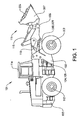
- Fig 1 shows a side view of a wheel loader 101.
- the wheel loader 101 comprises a front vehicle part 102 and a rear vehicle part 103, which parts each comprise a frame and a pair of drive axles 112, 113.
- the rear vehicle part 103 comprises a cab 114.
- the vehicle parts 102, 103 are coupled together with one another in such a way that they can be pivoted in relation to one another about a vertical axis by means of two hydraulic cylinders 104, 105 which are connected to the two parts.
- the hydraulic cylinders 104, 105 are thus arranged on different sides of a center line in the longitudinal direction of the vehicle for steering, or turning the wheel loader 101.
- the wheel loader 101 comprises an apparatus 111 for handling objects or material.
- the apparatus 111 comprises a lifting arm unit 106 and an implement 107 in the form of a bucket which is mounted on the lifting arm unit.
- the bucket 107 is filled with material 116.
- a first end of the lifting arm unit 106 is coupled rotatably to the front vehicle part 102 for bringing about a lifting movement of the bucket.
- the bucket 107 is coupled rotatably to a second end of the lifting arm unit 106 for bringing about a tilting movement of the bucket.
- the lifting arm unit 106 can be raised and lowered in relation to the front part 102 of the vehicle by means of two hydraulic cylinders 108, 109, which are each coupled at one end to the front vehicle part 102 and at the other end to the lifting arm unit 106.
- the bucket 107 can be tilted in relation to the lifting arm unit 106 by means of a third hydraulic cylinder 110, which is coupled at one end to the front vehicle part 102 and at the other end to the bucket 107 via a link arm system.
- Figure 2 shows a first embodiment of a control system 201 for performing load-arm springing of the lifting arm 106, see figure 1 .
- the hydraulic cylinder 108 in figure 2 therefore corresponds to the lifting cylinders 108, 109 (although only one cylinder is shown in figure 2 ).
- the control system 201 comprises an electric machine 202, a hydraulic machine 204 and the lifting cylinder 108.
- the electric machine 202 is connected in a mechanically driving manner to the hydraulic machine 204 via an intermediate drive shaft 206.
- the hydraulic machine 204 is connected to a piston side 208 of the hydraulic cylinder 108 via a first line 210 and a piston-rod side 212 of the hydraulic cylinder 108 via a second line 214.
- the hydraulic machine 204 is adapted to function as a pump, be driven by the electric machine 202 and supply the hydraulic cylinder 108 with pressurized hydraulic fluid from a tank 216 in a first operating state and to function as a motor, be driven by a hydraulic fluid flow from the hydraulic cylinder 108 and drive the electric machine 202 in a second operating state.
- the hydraulic machine 204 is adapted to control the speed of the piston 218 of the hydraulic cylinder 108 in the first operating state. No control valves are therefore required between the hydraulic machine and the hydraulic cylinder for said control. More precisely, the control system 201 comprises a control unit 402, see figure 4 , which is electrically connected to the electric machine 202 in order to control the speed of the piston of the hydraulic cylinder 108 in the first operating state by controlling the electric machine.
- the hydraulic machine 204 has a first port 220 which is connected to the piston side 208 of the hydraulic cylinder via the first line 210 and a second port 222 which is connected to the piston-rod side 212 of the hydraulic cylinder via the second line 214.
- the second port 222 of the hydraulic machine 204 is moreover connected to the tank 216 in order to allow the hydraulic machine, in the first operating state, to draw oil from the tank 216 via the second port 222 and supply the oil to the hydraulic cylinder 108 via the first port 220.
- the control system 201 comprises a means 224 for controlling pressure, which pressure means 224 is arranged on a line 226 between the second port 222 of the hydraulic machine 204 and the tank 216 in order to allow pressure build-up on the piston-rod side 212. More precisely, the pressure control means 224 comprises an electrically controlled pressure-limiting valve.
- the control system 201 also comprises a sensor 228 for sensing pressure on the piston side 208 of the hydraulic cylinder 108.
- the first port 220 of the hydraulic machine 204 is connected to the tank 216 via a first suction line 230.
- a means 232 in the form of a non-return valve, is adapted to allow suction of hydraulic fluid from the tank and obstruction of a hydraulic fluid flow to the tank through the suction line 230.
- the second port 222 of the hydraulic machine 204 is connected to the tank 216 via a second suction line 234.
- a means 236, in the form of a non-return valve, is adapted to allow suction of hydraulic fluid from the tank and obstruction of a hydraulic fluid flow to the tank through the suction line 234.
- a means 237 for opening/closing is arranged on the second line 214 between the second port 222 of the hydraulic machine 204 and the piston-rod end 212 of the hydraulic cylinder 108.
- This means 237 comprises an electrically controlled valve with two positions. In a first position, the line 214 is open for flow in both directions. In a second position, the valve has a non-return valve function and allows flow in only the direction toward the hydraulic cylinder 108.
- the electric valve 237 is opened and the rotational speed of the electric machine 202 determines the speed of the piston 218 of the hydraulic cylinder 108. Hydraulic fluid is drawn from the tank 216 via the second suction line 234 and is pumped to the piston side 208 of the hydraulic cylinder 108 via the first line 210.
- An additional line 242 connects the second port 222 of the hydraulic machine 204 and the tank 216.
- a means 243 for opening/closing is arranged on the first line 210 between the first port 220 of the hydraulic machine 204 and the piston end 208 of the hydraulic cylinder 108.
- This means 243 comprises an electrically controlled valve with two positions. In a first position, the line 210 is open for flow in both directions. In a second position, the valve has a non-return valve function and allows flow in only the direction toward the hydraulic cylinder 108.
- hydraulic fluid can be drawn from the tank 216 via the suction line 230 and on through the additional line 242.
- the electrically controlled valves 237, 243 function as load-holding valves. They are closed in order that electricity is not consumed when there is a hanging load and also in order to prevent dropping when the drive source is switched off. According to an alternative, the valve 237 on the piston-rod side 212 is omitted. However, it is advantageous to retain the valve 237 because disturbances can lift the lifting arm 106.
- a filtering unit 238 and a heat exchanger 240 are arranged on the additional line 242 between the second port 222 of the hydraulic machine 204 and the tank 216.
- An additional filtering and heating flow can be obtained by virtue of the hydraulic machine 204 driving a circulation flow from the tank 216 first via the first suction line 230 and then via the additional line 242 when the lifting function is in a neutral position. Before the tank, the hydraulic fluid thus passes through the heat exchanger 240 and the filter unit 238.
- the electrically controlled pressure limiter 224 can be used as a back-up valve for refilling the piston-rod side 212 when lowering is carried out.
- the back pressure can be varied as required and can be kept as low as possible, which saves energy. The hotter the oil, the lower the back pressure can be, and the slower the rate of lowering, the lower the back pressure can be. When there is a filtration flow, the back pressure can be zero.
- a first pressure-limiting valve 245 is arranged on a line which connects the first port 220 of the hydraulic machine 204 to the tank 216.
- a second pressure-limiting valve 247 is arranged on a line which connects the piston side 208 of the hydraulic cylinder 108 to the tank 216.
- the two pressure-limiting valves 245, 247 are connected to the first line 210 between the hydraulic machine 204 and the piston side 208 of the hydraulic cylinder 108 on different sides of the valve 243.
- the two pressure-limiting valves 245, 247 which are also referred to as shock valves, are spring-loaded and adjusted to be opened at different pressures. According to an example, the first pressure-limiting valve 245 is adjusted to be opened at 270 bar, and the second pressure-limiting valve 247 is adjusted to be opened at 380 bar.
- the bucket 107 is in a neutral position, that is to say stationary in relation to the frame of the front vehicle part 102.
- the second pressure limiter 247 is opened at a pressure of 380 bar.
- the valve 243 on the first line 210 between the hydraulic machine 204 and the piston side 208 of the hydraulic cylinder 108 is open.
- the first pressure limiter 245 is opened at a pressure of 270 bar. If a disturbance should force the loading arm 106 upward during a lowering operation with power down, the pressure limiter 224 on the line 226 between the second port 222 of the hydraulic machine 204 and the tank 216 is opened.
- the pressure-limiting valves 245, 247 can be designed with variable opening pressure.
- the pressure-limiting valves 245, 247 are electrically controlled. If electric control is used, only one valve 247 is sufficient for the shock function. This valve 247 is controlled depending on whether the valve 243 is open or closed. The opening pressure can be adjusted depending on activated or non-activated lifting/lowering function and also depending on the cylinder position.
- the method can be said to consist of an active springing system for the lift function.
- the method can either be selected by an operator via a control in the cab, such as a knob or lever, or can be initiated automatically.
- a sensor 248 is arranged to detect the position of the lifting arm 106 in relation to the frame of the front part 102 of the vehicle.
- the sensor 248 is here arranged to detect the position of the piston rod.
- the sensor 248 could detect the angular position of the load arm 106 in relation to the frame.
- the sensor 248 detects the position of the implement repeatedly, essentially continuously, and produces corresponding signals.
- a control unit 402 receives the position signals from the sensor 248.
- the control unit 402 is normally called a CPU (Central Processing Unit) and comprises a microprocessor and a memory.
- CPU Central Processing Unit
- the position of the load arm 106 is stored in the memory before the function is activated. Upon activation of the function, both the valves 237 and 243 are opened on both sides of the lifting cylinder 108.
- the hydraulic machine 204 is controlled in such a way that a pressure is supplied to the hydraulic cylinder 108 that is such that the implement 107 is brought to a home position. The load arm 106 is thus held in position with a certain torque.
- the load arm 106 During movement of the wheel loader 101, that is to say during transportation, the load arm 106 will be acted upon by vertical forces, as a result of the weight of the load and unevenness in the ground, and will move up and down.
- the sensor 248 records such disturbances that result in the load arm 106 being moved from the home position.
- control unit 802 records this.
- the control unit controls the hydraulic machine 204 (via the electric machine 202) so that the hydraulic machine turns with a certain torque and refills the piston side 208 with hydraulic fluid.
- the applied torque decreases, depending on how far the lifting arm 106 is from the home position. A springing function is thereby achieved.
- the control unit 802 sends a signal to the electric machine 202 that allows the hydraulic machine 204 to be driven by a flow of hydraulic fluid from the hydraulic cylinder 108, and the energy from the hydraulic machine 204 is regenerated in the electric machine 202.
- the lifting arm 106 moves downward, it passes through the home position, whereby the reverse torque of the electric machine 204 increases, so that the movement of the lifting arm is retarded and finally ceases. Following this, oil is pumped into the cylinder 108 so that the lifting arm 106 moves upward again.
- the hydraulic cylinder 108 is controlled continuously, so that the implement 107 is kept within a predetermined range around the home position. In addition, adjustment is carried out continuously between the instances of a disturbance acting upon the implement, so that the load arm 106 does not deviate too far from the home position.
- valve 243 on the piston side 208 can be closed temporarily in order to save the energy that is required to hold the load.
- the valve 243 can be kept closed as long as no downward movement takes place. The valve 243 can thus be controlled actively and continuously to achieve energy-efficient operation.
- the function also damps shocks that arise through disturbances such as, for example, hitting something with the bucket 107.
- pressure sensors are used to record the sequence of pressure variations that arise in the event of a disturbance acting upon the implement. If pressure sensors are used, the valve 243 on the piston side 208 can, if required, be closed, provided that no lowering movement takes place (this depends on how quickly it can open in the event of a disturbance acting upon the implement). The disturbance acting upon the implement can, of course, also be recorded by a combination of position sensors and pressure sensors.
- the hydraulic machine 204 is controlled in such a way that a springing function is achieved.
- a disturbance urges the lifting arm 106 downward
- the hydraulic machine 204 regenerates electricity and, at the same time, the torque is increased so that retarding of the movement takes place (like the action of a spring).
- a function for controlling the movement in this case, the spring characteristic
- the spring characteristics are dependent upon the following parameters:
- Said function for controlling the movement does not necessarily have to resemble a spring.
- the spring force increases with increased stroke length.
- a constant force and hence constant torque
- the springing constant can be changed, dependent upon the displacement of the hydraulic machine or the movement of the hydraulic cylinder.
- the damping in the system is determined by the size of the torque that the pump applies when the unit is to be raised again after it has been urged downwards.
- This applied torque (spring characteristic) can also be a function of the abovementioned parameters.
- the damping can be explained as the characteristic of the quantity of energy that is regenerated.
- the degree of damping is a combination of the size of the quantity of energy that is regenerated, the pressure drop in the system and the friction in the system.
- the position of the piston rod in the lifting cylinder is detected by a linear sensor or, alternatively, the angle of the load arm is detected by an angle sensor and the springing and/or damping of the lift function is controlled in response to the position.
- the position of the implement is detected, for example by the position of the piston rod in the tilting cylinder or by an angle sensor, and the springing and/or damping of the lift function is controlled in response to the position.
- the position parameter is preferably detected repeatedly, suitably essentially continuously, and the springing/damping is controlled correspondingly.
- the speed of the work machine, the current work being carried out by the work machine, the type of implement that is arranged on the work machine, and/or a mode selected by the driver is detected and the springing and/or damping of the lift function is controlled correspondingly.
- work being carried out is meant here an activity, such as handling/transportation of chippings, gravel, rubble, timber, pallets, snow-clearing, etc.
- type of implement is meant here different implements, such as bucket, pallet forks, grab arms for timber etc.
- the type of implement can, for example, be detected automatically or can be selected manually by the driver.
- the work being carried out can either be determined automatically during operation of the machine or can be selected manually by the driver. Consequently, by mode is meant either work being carried out or type of implement.
- a combination of a plurality of the abovementioned parameters is preferably used to determine how the springing/damping is to be controlled.
- Figure 3 illustrates a flow diagram for the logic circuit in the method for the springing of the load arm according to an alternative.
- the logic circuit commences at the initial block 301 when a signal is received from a control 406 to the effect that springing of the load arm is to be activated. Following this, the control unit continues to block 303, where a signal from the sensor 248 that detects the position of the piston rod is read off. In the next block 305, a home position is defined, corresponding to the detected position of the piston rod. A signal is sent to the electric machine 202 in order to apply a torque to the hydraulic machine 204 so that the implement will be held in the home position, see block 307.
- signals are sent to the valves 237, 243 in order to open these, see block 309, and thereby connect the hydraulic machine to the piston side and the piston-rod side.
- signals from the sensor 248 that detects the position of the piston rod are read off continuously, see block 311, and the electric machine 202 is controlled in response to the detected positions, see block 313.
- Figure 4 shows a control system for the lowering function.
- An element or control 406 for activating the springing of the load arm is arranged in the cab 114 for manual operation by the driver and is electrically connected to the control unit 402.
- the electric machine 202 is electrically connected to the control unit 402 in such a way that it is controlled by the control unit and can supply signals about the operating conditions to the control unit.
- the control system comprises one or more energy storage means 420 connected to said electric machine 202.
- the energy storage means 420 can consist of a battery or a supercapacitor, for example.
- the energy storage means 420 is adapted to provide the electric machine with energy when the electric machine 202 is to function as a motor and drive its associated pump 204.
- the electric machine 202 is adapted to charge the energy storage means 420 with energy when the electric machine 202 is driven by its associated pump 204 and functions as a generator.
- the wheel loader 101 also comprises a power source 422 in the form of an internal combustion engine, which usually comprises a diesel engine, for propulsion of the vehicle.
- the diesel engine is connected in a driving manner to the wheels of the vehicle via a drive line (not shown).
- the diesel engine is moreover connected to the energy storage means 420 via a generator (not shown) for energy transmission.
- Figure 4 also shows the other components which are connected to the control unit 402 according to the first embodiment of the control system for the lifting function, see figure 2 , such as the electrically controlled valves 224, 237, 243, the position sensor 248 and the pressure sensor 228.
- the piston-rod side can be connected to the tank.
- a parameter is detected that is indicative of a different function than the function that is to be sprung/damped and the springing/damping is controlled correspondingly.
- a steering movement is detected (via the steering cylinders 104, 105) and the springing/damping of the lift function (via the lifting cylinders 108, 109) is controlled correspondingly.
Landscapes
- Engineering & Computer Science (AREA)
- General Engineering & Computer Science (AREA)
- Mining & Mineral Resources (AREA)
- Civil Engineering (AREA)
- Structural Engineering (AREA)
- Mechanical Engineering (AREA)
- Physics & Mathematics (AREA)
- Fluid Mechanics (AREA)
- Chemical & Material Sciences (AREA)
- Analytical Chemistry (AREA)
- Combustion & Propulsion (AREA)
- Operation Control Of Excavators (AREA)
- Fluid-Pressure Circuits (AREA)
- Lifting Devices For Agricultural Implements (AREA)
Claims (27)
- Verfahren zur Abfederung einer Bewegung eines Geräts (107) einer Arbeitsmaschine (101) während einer Bewegung der Arbeitsmaschine, in der wenigstens ein Hydraulikzylinder (104, 105, 108, 109, 110) funktionell mit dem Gerät verbunden ist, mit den Schritten, dass eine hydraulische Maschine (204) mit dem Hydraulikzylinder in Verbindung gebracht wird, und die hydraulische Maschine (204) in Ansprechung auf eine Störung des Geräts während seiner Bewegung gesteuert wird, indem es der hydraulischen Maschine (204) ermöglicht wird, von einer Strömung von Hydraulikfluid aus dem Hydraulikzylinder angetrieben zu werden, falls eine Störung auftritt, die in einer Abwärtsbewegung des Gerätes (107) resultiert, und der Wiedergewinnung der Energie von der hydraulischen Maschine (204) über eine elektrische Maschine (202), wobei die hydraulische Maschine (204) so ausgelegt ist, dass sie als Pumpe wirkt, die von der elektrischen Maschine (202) angetrieben wird und den Hydraulikzylinder (108, 109) mit unter Druck gesetztem Hydraulikfluid aus einem Tank (216) in einem ersten Betriebszustand versorgt, und als Motor wirkt, der durch eine hydraulische Fluidströmung von dem Hydraulikzylinder (108, 109) angetrieben wird und die elektrische Maschine (202) in einem zweiten Betriebszustand antreibt.
- Verfahren nach Anspruch 1, das den Schritt umfasst, dass die hydraulische Maschine (204) so gesteuert wird, dass die Abfederung der Bewegung des Geräts erreicht wird.
- Verfahren nach Anspruch 1 oder 2, das die Schritte umfasst, dass ein Parameter erfasst wird, der für die Position des Geräts indikativ ist, und dass die hydraulische Maschine (204) in Ansprechung auf die erfasste Position gesteuert wird.
- Verfahren nach Anspruch 3, das den Schritt umfasst, dass der Positionsparameter wiederholt erfasst wird.
- Verfahren nach irgendeinem vorhergehenden Anspruch, das den Schritt umfasst, dass der Hydraulikzylinder in einem solchen Ausmaß unter Druck gesetzt wird, dass das Gerät in eine Ausgangsposition gebracht wird.
- Verfahren nach Anspruch 5, das den Schritt umfasst, dass die hydraulische Maschine fortlaufend so gesteuert wird, dass das Gerät in einem vorherbestimmten Bereich um die Anfangsposition gehalten wird.
- Verfahren nach irgendeinem vorhergehenden Anspruch, das die Schritte umfasst, dass ein Parameter erfasst wird, der für die Position des Gerätes bei Beginn des Verfahrens indikativ ist, dass die erfasste Position bei Beginn als Anfangsposition definiert wird und dass die hydraulische Maschine (204) so gesteuert wird, dass das Gerät in der Anfangsposition gehalten wird, wenn die hydraulische Maschine (204) mit dem Hydraulikzylinder verbunden ist.
- Verfahren nach irgendeinem vorhergehenden Anspruch, das den Schritt umfasst, dass der Zylinder mit einer entsprechenden Menge an Hydraulikfluid versorgt wird, falls eine Störung auftritt, die in einer Aufwärtsbewegung des Geräts resultiert.
- Verfahren nach irgendeinem vorhergehenden Anspruch, das den Schritt umfasst, dass wenigstens eine entsprechende Menge von Hydraulikfluid aus dem Hydraulikzylinder abgelassen wird, falls eine Störung auftritt, die in einer Abwärtsbewegung des Geräts resultiert.
- Verfahren nach irgendeinem vorhergehenden Anspruch, das den Schritt umfasst, dass ein erster Kanal (220) an der hydraulischen Maschine (204) mit einer Kolbenseite (208) des Hydraulikzylinders über eine erste Leitung (210) in Verbindung gebracht wird.
- Verfahren nach irgendeinem vorhergehenden Anspruch, das den Schritt umfasst, dass ein zweiter Kanal (222) an der hydraulischen Maschine (204) mit einer Kolbenstangenseite (212) des Hydraulikzylinders über eine zweite Leitung (214) in Verbindung gebracht wird.
- Verfahren nach irgendeinem vorhergehenden Anspruch, das den Schritt umfasst, dass die hydraulische Maschine (204) über eine elektrische Maschine (202) gesteuert wird.
- Verfahren nach irgendeinem vorhergehenden Anspruch, das die Schritte umfasst, dass wenigstens ein Betriebsparameter erfasst wird und die Abfederungsbewegung einer Funktion entsprechend in Ansprechung auf den erfassten Betriebsparameter gesteuert wird.
- Verfahren nach irgendeinem vorhergehenden Anspruch, das die Schritte umfasst, dass wenigstens ein Betriebsparameter erfasst wird und eine Dämpfung in Ansprechung auf den erfassten Betriebsparameter gesteuert wird.
- Verfahren nach Anspruch 13 oder 14, das die Schritte umfasst, dass die Höhe einer Störkraft erfasst wird und die Abfederung und/oder Dämpfung in Ansprechung auf die Höhe der Störkraft gesteuert wird, die auf das Gerät wirkt.
- Verfahren nach irgendeinem der Ansprüche 13 bis 15, das die Schritte umfasst, dass das Gewicht der Last erfasst wird und die Abfederung und/oder Dämpfung in Ansprechung auf das Gewicht gesteuert wird.
- Verfahren nach irgendeinem der Ansprüche 13 bis 16, das die Schritte umfasst, dass bestimmt wird, welche Art Gerät verwendet wird, und dass die Abfederung und/oder Dämpfung abhängig von der Art des Geräts gesteuert wird.
- Verfahren nach irgendeinem der Ansprüche 13 bis 17, das die Schritte umfasst, dass die Art der durchgeführten Arbeit bestimmt wird und die Abfederung und/oder Dämpfung abhängig von der durchgeführten Arbeit gesteuert wird.
- Verfahren nach irgendeinem der Ansprüche 13 bis 18, das die Schritte umfasst, dass ein Parameter erfasst wird, der für die Position des Geräts indikativ ist, und dass die Abfederung und/oder Dämpfung in Ansprechung auf die Position gesteuert wird.
- Verfahren nach irgendeinem der Ansprüche 13 bis 19, das die Schritte umfasst, dass ein Parameter erfasst wird, der für eine Funktion indikativ ist, die sich von der Funktion unterscheidet, für die die hydraulische Maschine zur Druckversorgung angeordnet ist, und dass die Abfederung und/oder Dämpfung in Ansprechung auf den erfassten Parameter gesteuert wird.
- Verfahren nach irgendeinem der Ansprüche 13 bis 20, das den Schritt umfasst, dass die Geschwindigkeit der Arbeitsmaschine erfasst wird, und die Abfederung und/oder Dämpfung in Ansprechung auf die Geschwindigkeit gesteuert wird.
- Verfahren nach irgendeinem vorhergehenden Anspruch, das die Schritte umfasst, dass ein Ventil (237, 243) auf der Kolbenseite oder der Kolbenstangenseite (212) des Hydraulikzylinders geöffnet wird, um die hydraulische Maschine (204) mit dem Hydraulikzylinder zu verbinden.
- Verfahren nach irgendeinem vorhergehenden Anspruch, das den Schritt umfasst, dass die Störung über einen Positionssensor (248) für die Funktion aufgezeichnet wird, die durch den Hydraulikzylinder gesteuert wird.
- Verfahren nach irgendeinem vorhergehenden Anspruch, das den Schritt umfasst, dass die Störung über einen Drucksensor (228) für die Funktion aufgezeichnet wird, die durch den Hydraulikzylinder gesteuert wird.
- Verfahren nach irgendeinem vorhergehenden Anspruch, bei dem der Hydraulikzylinder (108, 109) einen Hebezylinder bildet und mit dem Gerät über einen Lastarm (106) verbunden ist.
- Verfahren nach irgendeinem der Ansprüche 1 bis 24, bei dem der Hydraulikzylinder (110) ein Kippzylinder ist.
- Verfahren nach irgendeinem der Ansprüche 1 bis 24, bei dem der Hydraulikzylinder (104, 105) ein Lenkzylinder ist.
Applications Claiming Priority (3)
| Application Number | Priority Date | Filing Date | Title |
|---|---|---|---|
| SE0600087A SE531309C2 (sv) | 2006-01-16 | 2006-01-16 | Styrsystem för en arbetsmaskin och förfarande för styrning av en hydraulcylinder hos en arbetsmaskin |
| US75999606P | 2006-01-18 | 2006-01-18 | |
| PCT/SE2007/000040 WO2007081280A1 (en) | 2006-01-16 | 2007-01-16 | Method for springing a movement of an implement of a work machine |
Publications (3)
| Publication Number | Publication Date |
|---|---|
| EP1979548A1 EP1979548A1 (de) | 2008-10-15 |
| EP1979548A4 EP1979548A4 (de) | 2012-03-14 |
| EP1979548B1 true EP1979548B1 (de) | 2013-03-20 |
Family
ID=38331484
Family Applications (6)
| Application Number | Title | Priority Date | Filing Date |
|---|---|---|---|
| EP07717736.8A Not-in-force EP1979550B1 (de) | 2006-01-16 | 2007-01-16 | Verfahren zur steuerung eines hydraulischen gerätes in einem steuersystem |
| EP07701117.9A Not-in-force EP1979547B1 (de) | 2006-01-16 | 2007-01-16 | Verfahren zur steuerung eines hydraulikzylinders in einer arbeitsmaschine und steuersystem für eine arbeitsmaschine |
| EP07701124.5A Not-in-force EP1979549B1 (de) | 2006-01-16 | 2007-01-16 | Verfahren zur steuerung eines hydraulikzylinders in einer arbeitsmaschine |
| EP07717946.3A Not-in-force EP1979551B1 (de) | 2006-01-16 | 2007-01-16 | Steuerungssystem für eine arbeitsmaschine und verfahren zur steuerung eines hydraulischen zylinders |
| EP07701123A Not-in-force EP1979548B1 (de) | 2006-01-16 | 2007-01-16 | Verfahren zur federung einer bewegung eines einsatzes einer arbeitsmaschine |
| EP07701116.1A Not-in-force EP1979546B1 (de) | 2006-01-16 | 2007-01-16 | Verfahren zur steuerung eines hydraulikzylinders in einer arbeitsmaschine und steuersystem für eine arbeitsmaschine |
Family Applications Before (4)
| Application Number | Title | Priority Date | Filing Date |
|---|---|---|---|
| EP07717736.8A Not-in-force EP1979550B1 (de) | 2006-01-16 | 2007-01-16 | Verfahren zur steuerung eines hydraulischen gerätes in einem steuersystem |
| EP07701117.9A Not-in-force EP1979547B1 (de) | 2006-01-16 | 2007-01-16 | Verfahren zur steuerung eines hydraulikzylinders in einer arbeitsmaschine und steuersystem für eine arbeitsmaschine |
| EP07701124.5A Not-in-force EP1979549B1 (de) | 2006-01-16 | 2007-01-16 | Verfahren zur steuerung eines hydraulikzylinders in einer arbeitsmaschine |
| EP07717946.3A Not-in-force EP1979551B1 (de) | 2006-01-16 | 2007-01-16 | Steuerungssystem für eine arbeitsmaschine und verfahren zur steuerung eines hydraulischen zylinders |
Family Applications After (1)
| Application Number | Title | Priority Date | Filing Date |
|---|---|---|---|
| EP07701116.1A Not-in-force EP1979546B1 (de) | 2006-01-16 | 2007-01-16 | Verfahren zur steuerung eines hydraulikzylinders in einer arbeitsmaschine und steuersystem für eine arbeitsmaschine |
Country Status (5)
| Country | Link |
|---|---|
| US (7) | US7908048B2 (de) |
| EP (6) | EP1979550B1 (de) |
| CN (6) | CN101370985B (de) |
| SE (1) | SE531309C2 (de) |
| WO (6) | WO2007081277A1 (de) |
Families Citing this family (113)
| Publication number | Priority date | Publication date | Assignee | Title |
|---|---|---|---|---|
| CA2588290A1 (en) | 2004-12-01 | 2006-06-08 | Haldex Hydraulics Corporation | Hydraulic drive system |
| SE531309C2 (sv) * | 2006-01-16 | 2009-02-17 | Volvo Constr Equip Ab | Styrsystem för en arbetsmaskin och förfarande för styrning av en hydraulcylinder hos en arbetsmaskin |
| DE102006042372A1 (de) * | 2006-09-08 | 2008-03-27 | Deere & Company, Moline | Ladegerät |
| DE102008034301B4 (de) | 2007-12-04 | 2019-02-14 | Robert Bosch Gmbh | Hydraulisches System mit einem verstellbaren Schnellsenkventil |
| US20110064706A1 (en) * | 2008-01-11 | 2011-03-17 | U.S. Nutraceuticals, Llc D/B/A Valensa International | Method of preventing, controlling and ameliorating urinary tract infections and supporting digestive health by using a synergistic cranberry derivative, a d-mannose composition and a proprietary probiotic blend |
| WO2009094492A2 (en) * | 2008-01-23 | 2009-07-30 | Parker-Hannifin Corporation | Electro-hydraulic machine for hybri drive system |
| US8160783B2 (en) * | 2008-06-30 | 2012-04-17 | Caterpillar Inc. | Digging control system |
| WO2010028100A1 (en) | 2008-09-03 | 2010-03-11 | Parker Hannifin Corporation | Velocity control of unbalanced hydraulic actuator subjected to over-center load conditions |
| US20110056192A1 (en) * | 2009-09-10 | 2011-03-10 | Robert Weber | Technique for controlling pumps in a hydraulic system |
| US20110056194A1 (en) * | 2009-09-10 | 2011-03-10 | Bucyrus International, Inc. | Hydraulic system for heavy equipment |
| US8362629B2 (en) * | 2010-03-23 | 2013-01-29 | Bucyrus International Inc. | Energy management system for heavy equipment |
| JP5600274B2 (ja) * | 2010-08-18 | 2014-10-01 | 川崎重工業株式会社 | 作業機械の電液駆動システム |
| US20120055149A1 (en) * | 2010-09-02 | 2012-03-08 | Bucyrus International, Inc. | Semi-closed hydraulic systems |
| DE102010040754A1 (de) * | 2010-09-14 | 2012-03-15 | Zf Friedrichshafen Ag | Hydraulische Antriebsanordnung |
| US8626403B2 (en) * | 2010-10-06 | 2014-01-07 | Caterpillar Global Mining Llc | Energy management and storage system |
| US8606451B2 (en) | 2010-10-06 | 2013-12-10 | Caterpillar Global Mining Llc | Energy system for heavy equipment |
| US8718845B2 (en) | 2010-10-06 | 2014-05-06 | Caterpillar Global Mining Llc | Energy management system for heavy equipment |
| EP2466017A1 (de) * | 2010-12-14 | 2012-06-20 | Caterpillar, Inc. | Hydraulischer Antrieb mit geschlossenem Kreis mit Unterstützung einer Pumpe aus einem offenen Kreis für Hochgeschwindigkeitsfahrbewegungen |
| JP5509433B2 (ja) * | 2011-03-22 | 2014-06-04 | 日立建機株式会社 | ハイブリッド式建設機械及びこれに用いる補助制御装置 |
| US8833067B2 (en) * | 2011-04-18 | 2014-09-16 | Caterpillar Inc. | Load holding for meterless control of actuators |
| EP2700827A4 (de) * | 2011-04-19 | 2015-03-11 | Volvo Constr Equip Ab | Hydraulikkreis zur steuerung der ausleger einer baumaschine |
| US8666574B2 (en) * | 2011-04-21 | 2014-03-04 | Deere & Company | In-vehicle estimation of electric traction motor performance |
| EP2940319B1 (de) * | 2011-05-31 | 2019-03-13 | Volvo Construction Equipment AB | Hydraulisches system und verfahren zur steuerung eines hydraulischen systems |
| US8886415B2 (en) * | 2011-06-16 | 2014-11-11 | Caterpillar Inc. | System implementing parallel lift for range of angles |
| WO2013000155A1 (zh) * | 2011-06-30 | 2013-01-03 | Lio Pang-Chian | 液压远端传动控制装置 |
| JP5752526B2 (ja) * | 2011-08-24 | 2015-07-22 | 株式会社小松製作所 | 油圧駆動システム |
| US8944103B2 (en) | 2011-08-31 | 2015-02-03 | Caterpillar Inc. | Meterless hydraulic system having displacement control valve |
| US8863509B2 (en) * | 2011-08-31 | 2014-10-21 | Caterpillar Inc. | Meterless hydraulic system having load-holding bypass |
| CN103781972B (zh) * | 2011-09-09 | 2016-08-24 | 住友重机械工业株式会社 | 挖土机以及挖土机的控制方法 |
| US9506225B2 (en) * | 2011-10-11 | 2016-11-29 | Volvo Construction Equipment Ab | Actuator displacement measurement system in electronic hydraulic system of construction equipment |
| US9080310B2 (en) * | 2011-10-21 | 2015-07-14 | Caterpillar Inc. | Closed-loop hydraulic system having regeneration configuration |
| CN104053843B (zh) * | 2011-10-27 | 2016-06-22 | 沃尔沃建造设备有限公司 | 设置有致动器冲击降低系统的混合动力挖掘机 |
| US9096115B2 (en) | 2011-11-17 | 2015-08-04 | Caterpillar Inc. | System and method for energy recovery |
| CN102493976B (zh) * | 2011-12-01 | 2014-12-10 | 三一重工股份有限公司 | 一种工程机械的动力控制系统及控制方法 |
| CA2798030A1 (en) * | 2011-12-05 | 2013-06-05 | Fabio Saposnik | Fluid power driven charger |
| US10125798B2 (en) * | 2011-12-22 | 2018-11-13 | Volvo Construction Equipment Ab | Method for controlling lowering of an implement of a working machine |
| EP2795002B1 (de) * | 2011-12-23 | 2022-03-30 | J.C. Bamford Excavators Limited | Hydraulisches system mit einer vorrichtung zur speicherung kinetischer energie |
| JP5730794B2 (ja) * | 2012-01-18 | 2015-06-10 | 住友重機械工業株式会社 | 建設機械のエネルギ回生装置 |
| US20130189062A1 (en) * | 2012-01-23 | 2013-07-25 | Paul Bark | Hydraulic pump control system for lift gate applications |
| DE102012101231A1 (de) * | 2012-02-16 | 2013-08-22 | Linde Material Handling Gmbh | Hydrostatisches Antriebssystem |
| JP5928065B2 (ja) * | 2012-03-27 | 2016-06-01 | コベルコ建機株式会社 | 制御装置及びこれを備えた建設機械 |
| CA2869935C (en) | 2012-04-11 | 2020-01-07 | Clark Equipment Company | Lift arm suspension system for a power machine |
| US8825314B2 (en) * | 2012-07-31 | 2014-09-02 | Caterpillar Inc. | Work machine drive train torque vectoring |
| US9190852B2 (en) | 2012-09-21 | 2015-11-17 | Caterpillar Global Mining Llc | Systems and methods for stabilizing power rate of change within generator based applications |
| AU2013201057B2 (en) * | 2012-11-06 | 2014-11-20 | SINGH, Kalvin Jit MR | Improvements in and Relating to Load Transfer |
| US9897112B2 (en) | 2012-11-07 | 2018-02-20 | Parker-Hannifin Corporation | Smooth control of hydraulic actuator |
| KR102067992B1 (ko) * | 2012-11-07 | 2020-02-11 | 파커-한니핀 코포레이션 | 전기 정유압 액추에이터 감속률 제어 시스템 |
| US9279736B2 (en) | 2012-12-18 | 2016-03-08 | Caterpillar Inc. | System and method for calibrating hydraulic valves |
| US9360023B2 (en) * | 2013-03-14 | 2016-06-07 | The Raymond Corporation | Hydraulic regeneration system and method for a material handling vehicle |
| CN105339682B (zh) | 2013-04-19 | 2017-06-13 | 派克汉尼芬公司 | 检测液压系统中的液压阀故障的方法 |
| WO2014176252A1 (en) * | 2013-04-22 | 2014-10-30 | Parker-Hannifin Corporation | Method of increasing electro-hydrostatic actuator piston velocity |
| US9670943B2 (en) | 2013-04-22 | 2017-06-06 | Parker-Hannifin Corporation | Method for controlling pressure in a hydraulic actuator |
| WO2015019594A1 (ja) * | 2013-08-05 | 2015-02-12 | 川崎重工業株式会社 | 建設機械用エネルギ回生装置 |
| JP2015137753A (ja) * | 2014-01-24 | 2015-07-30 | カヤバ工業株式会社 | ハイブリッド建設機械の制御システム |
| CN105940356A (zh) * | 2014-01-27 | 2016-09-14 | 沃尔沃建造设备有限公司 | 用于控制工程机械的再生流量的装置及其控制方法 |
| WO2015131196A1 (en) | 2014-02-28 | 2015-09-03 | Project Phoenix, LLC | Pump integrated with two independently driven prime movers |
| WO2015148662A1 (en) | 2014-03-25 | 2015-10-01 | Afshari Thomas | System to pump fluid and control thereof |
| EP3126581B1 (de) | 2014-04-04 | 2020-04-29 | Volvo Construction Equipment AB | Hydraulisches system und verfahren zur steuerung einer vorrichtung einer arbeitsmaschine |
| EP3134648B1 (de) | 2014-04-22 | 2023-06-14 | Project Phoenix, LLC | Flüssigkeitsabgabesystem mit einer welle mit durchgang |
| EP3730793B1 (de) * | 2014-06-02 | 2022-04-27 | Project Phoenix LLC | Linearaktuatoranordnung und -system |
| EP3149362B1 (de) | 2014-06-02 | 2019-04-10 | Project Phoenix LLC | Hydrostatische getriebeanordnung und system |
| EP2955389B1 (de) * | 2014-06-13 | 2019-05-22 | Parker Hannifin Manufacturing Finland OY | Hydraulisches System mit Energierückgewinnung |
| KR102316426B1 (ko) | 2014-07-22 | 2021-10-21 | 프로젝트 피닉스, 엘엘씨 | 독립적으로 구동되는 2개의 원동기와 통합된 외부 기어 펌프 |
| US9546672B2 (en) | 2014-07-24 | 2017-01-17 | Google Inc. | Actuator limit controller |
| US9841101B2 (en) * | 2014-09-04 | 2017-12-12 | Cummins Power Generation Ip, Inc. | Control system for hydraulically powered AC generator |
| US10072676B2 (en) | 2014-09-23 | 2018-09-11 | Project Phoenix, LLC | System to pump fluid and control thereof |
| EP3204647B1 (de) | 2014-10-06 | 2021-05-26 | Project Phoenix LLC | Linearaktuatoranordnung und -system |
| WO2016064569A1 (en) | 2014-10-20 | 2016-04-28 | Afshari Thomas | Hydrostatic transmission assembly and system |
| US9759212B2 (en) * | 2015-01-05 | 2017-09-12 | Danfoss Power Solutions Inc. | Electronic load sense control with electronic variable load sense relief, variable working margin, and electronic torque limiting |
| EP3344874B1 (de) | 2015-09-02 | 2021-01-20 | Project Phoenix LLC | System zum pumpen einer flüssigkeit und steuerung dafür |
| TWI704286B (zh) | 2015-09-02 | 2020-09-11 | 美商鳳凰計劃股份有限公司 | 泵送流體之系統及其控制 |
| CN108351045B (zh) * | 2015-09-10 | 2021-02-09 | 费斯托股份两合公司 | 流体系统和过程阀 |
| US10598193B2 (en) * | 2015-10-23 | 2020-03-24 | Aoi | Prime mover system and methods utilizing balanced flow within bi-directional power units |
| DE102015119108A1 (de) * | 2015-11-06 | 2017-05-11 | Pleiger Maschinenbau Gmbh & Co. Kg | Verfahren und Vorrichtung zum Ansteuern einer hydraulisch betätigten Antriebseinheit einer Armatur |
| US9657675B1 (en) * | 2016-03-31 | 2017-05-23 | Etagen Inc. | Control of piston trajectory in a free-piston combustion engine |
| US10550863B1 (en) | 2016-05-19 | 2020-02-04 | Steven H. Marquardt | Direct link circuit |
| US11015624B2 (en) | 2016-05-19 | 2021-05-25 | Steven H. Marquardt | Methods and devices for conserving energy in fluid power production |
| US10914322B1 (en) | 2016-05-19 | 2021-02-09 | Steven H. Marquardt | Energy saving accumulator circuit |
| EP3509915B1 (de) * | 2016-09-06 | 2020-11-11 | Aperia Technologies, Inc. | Reifenfüllsystem |
| DE102016217541A1 (de) * | 2016-09-14 | 2018-03-15 | Robert Bosch Gmbh | Hydraulisches Antriebssystem mit mehreren Zulaufleitungen |
| CN106337849A (zh) * | 2016-11-23 | 2017-01-18 | 中冶赛迪工程技术股份有限公司 | 一种trt机组静叶直驱式电液伺服控制系统 |
| US10822772B1 (en) * | 2017-02-03 | 2020-11-03 | Wrightspeed, Inc. | Hydraulic systems with variable speed drives |
| EP3629725B1 (de) * | 2017-05-23 | 2021-03-31 | FSP Fluid Systems Partners Holding AG | Steuereinrichtung für eine ausbringvorrichtung und ausbringvorrichtung mit einer steuereinrichtung |
| US10392774B2 (en) | 2017-10-30 | 2019-08-27 | Deere & Company | Position control system and method for an implement of a work vehicle |
| DE102017131004A1 (de) * | 2017-12-21 | 2019-06-27 | Moog Gmbh | Stellantrieb mit hydraulischem Abflussverstärker |
| US11104234B2 (en) | 2018-07-12 | 2021-08-31 | Eaton Intelligent Power Limited | Power architecture for a vehicle such as an off-highway vehicle |
| US11408445B2 (en) | 2018-07-12 | 2022-08-09 | Danfoss Power Solutions Ii Technology A/S | Dual power electro-hydraulic motion control system |
| KR102586623B1 (ko) * | 2018-09-27 | 2023-10-10 | 볼보 컨스트럭션 이큅먼트 에이비 | 작업유닛 방출에너지 회생 시스템 및 방법 |
| WO2020083482A1 (en) * | 2018-10-24 | 2020-04-30 | Volvo Construction Equipment Ab | A hydraulic system for a working machine |
| DE102018128318A1 (de) * | 2018-11-13 | 2020-05-14 | Moog Luxembourg S.à.r.l. | Elektrohydrostatisches Aktuatorsystem |
| BE1027189B1 (nl) * | 2019-04-11 | 2020-11-10 | Gebroeders Geens N V | Aandrijfsysteem voor een werkvoertuig |
| EP3959383B1 (de) * | 2019-04-26 | 2023-06-07 | Volvo Construction Equipment AB | Hydraulisches system und verfahren zur steuerung eines hydraulischen systems einer arbeitsmaschine |
| NO349291B1 (no) | 2019-06-17 | 2025-11-24 | Conrobotix As | Sylinder, hydraulisk system, anleggsmaskin og fremgangsmåte |
| DE102019131980A1 (de) * | 2019-11-26 | 2021-05-27 | Moog Gmbh | Elektrohydrostatisches System mit Drucksensor |
| EP4073323A1 (de) * | 2019-12-12 | 2022-10-19 | Volvo Construction Equipment AB | Hydraulisches system und verfahren zur steuerung eines hydraulischen systems einer arbeitsmaschine |
| WO2021151505A1 (en) * | 2020-01-31 | 2021-08-05 | Volvo Construction Equipment Ab | Control system for assisting an operator of a working machine, corresponding method and computer program product |
| CN111350627B (zh) * | 2020-04-01 | 2020-11-27 | 东方电气自动控制工程有限公司 | 一种带手自动切换的液压调速控制系统 |
| WO2021225645A1 (en) * | 2020-05-05 | 2021-11-11 | Parker-Hannifin Corporation | Hydraulic dissipation of electric power |
| EP4179211A1 (de) | 2020-07-08 | 2023-05-17 | Project Phoenix, LLC | Dynamische steuerung von zahnrädern in einer zahnradpumpe mit einer antriebskonfiguration |
| TWI826800B (zh) | 2020-07-08 | 2023-12-21 | 美商鳳凰計劃股份有限公司 | 具有驅動-驅動組態的齒輪泵中之齒輪的動態控制 |
| JP2023548559A (ja) | 2020-11-05 | 2023-11-17 | メインスプリング エナジー, インコーポレイテッド | 線形発電機のためのコアの同期化 |
| CN112558645B (zh) * | 2020-11-06 | 2025-03-04 | 广东轻工职业技术大学 | 一种高精度可调流量输出装置 |
| US11654815B2 (en) * | 2021-02-01 | 2023-05-23 | Caterpillar Inc. | Closed center hoist valve with snubbing |
| DE102021123910A1 (de) * | 2021-09-15 | 2023-03-16 | HMS - Hybrid Motion Solutions GmbH | Hydraulisches Antriebssystem mit einer 4Q Pumpeneinheit |
| CN114251214B (zh) * | 2021-12-09 | 2023-01-24 | 中国船舶重工集团公司第七一九研究所 | 分数阶动力系统混沌状态的判断方法及装置 |
| CN114482184B (zh) * | 2022-02-28 | 2023-08-22 | 西安方元明鑫精密机电制造有限公司 | 一种基于伺服系统力矩控制的挖掘机用电动缸缓冲控制系统 |
| US20230312238A1 (en) * | 2022-03-31 | 2023-10-05 | Oshkosh Corporation | Hydraulic system for a refuse vehicle |
| JP7847485B2 (ja) * | 2022-06-23 | 2026-04-17 | 川崎重工業株式会社 | 液圧駆動装置 |
| JP7847487B2 (ja) * | 2022-06-23 | 2026-04-17 | 川崎重工業株式会社 | 液圧駆動装置 |
| CN114951580B (zh) * | 2022-06-27 | 2024-07-23 | 沈阳广泰真空科技股份有限公司 | 一种驱动冷却辊旋转的方法、装置、存储介质及电子设备 |
| DE102022121962A1 (de) * | 2022-08-31 | 2024-02-29 | Bucher Hydraulics Ag | Elektrisch-hydraulischer Aktor |
| CN115523206B (zh) * | 2022-10-27 | 2025-11-28 | 北京航空航天大学宁波创新研究院 | 液压缸控压系统及其控制方法 |
| DE102022211393A1 (de) | 2022-10-27 | 2024-05-02 | Robert Bosch Gesellschaft mit beschränkter Haftung | Hydraulische Anordnung mit Lasthaltefunktion und Steuerungsverfahren der hydraulischen Anordnung |
Family Cites Families (54)
| Publication number | Priority date | Publication date | Assignee | Title |
|---|---|---|---|---|
| US2590454A (en) * | 1949-09-13 | 1952-03-25 | John S Pilch | Hydraulic by-pass system and valve therefor |
| US3473325A (en) * | 1967-11-13 | 1969-10-21 | Eltra Corp | Unitary hydraulic shock absorber and actuator |
| US3604313A (en) * | 1970-05-14 | 1971-09-14 | Gen Signal Corp | Hydraulic power circuit with rapid lowering provisions |
| US4046270A (en) * | 1974-06-06 | 1977-09-06 | Marion Power Shovel Company, Inc. | Power shovel and crowd system therefor |
| SE396239B (sv) * | 1976-02-05 | 1977-09-12 | Hytec Ab | Metod och anordning for reglering av den effekt som tillfors ett hydrauliskt, ett pneumatiskt eller ett hydraulpneumatiskt system |
| US4509405A (en) * | 1979-08-20 | 1985-04-09 | Nl Industries, Inc. | Control valve system for blowout preventers |
| JPS56115428A (en) * | 1980-02-15 | 1981-09-10 | Hitachi Constr Mach Co Ltd | Hydraulic controller |
| JPS5822299A (ja) * | 1981-07-29 | 1983-02-09 | 日産自動車株式会社 | フオ−クリフト |
| DE3506335A1 (de) * | 1985-02-22 | 1986-08-28 | Mannesmann Rexroth GmbH, 8770 Lohr | Sicherheitsschaltung fuer ein hydrauliksystem |
| US4712376A (en) * | 1986-10-22 | 1987-12-15 | Caterpillar Inc. | Proportional valve control apparatus for fluid systems |
| DE3710028A1 (de) * | 1987-03-27 | 1988-10-06 | Delmag Maschinenfabrik | Druckmittelbetriebene antriebseinrichtung |
| SE461391B (sv) * | 1987-10-28 | 1990-02-12 | Bt Ind Ab | Hydraulisk lyftanordning |
| DE3886944T2 (de) * | 1988-05-24 | 1994-05-05 | Komatsu Mfg Co Ltd | Automatisches getriebe für radhebevorrichtung. |
| JPH0790400B2 (ja) * | 1989-10-18 | 1995-10-04 | アイダエンジニアリング株式会社 | プレスのダイクッション装置 |
| US5046309A (en) * | 1990-01-22 | 1991-09-10 | Shin Caterpillar Mitsubishi Ltd. | Energy regenerative circuit in a hydraulic apparatus |
| DE4008792A1 (de) * | 1990-03-19 | 1991-09-26 | Rexroth Mannesmann Gmbh | Antrieb fuer einen hydraulischen zylinder, insbesondere differentialzylinder |
| EP0526639B1 (de) * | 1990-04-24 | 1996-08-21 | Kabushiki Kaisha Komatsu Seisakusho | Schildhöhensteuerungsvorrichtung für kettenfahrzeuge |
| GB2250108B (en) * | 1990-10-31 | 1995-02-08 | Samsung Heavy Ind | Control system for automatically controlling actuators of an excavator |
| DE4402653C2 (de) * | 1994-01-29 | 1997-01-30 | Jungheinrich Ag | Hydraulische Hubvorrichtung für batteriebetriebene Flurförderzeuge |
| US5537818A (en) * | 1994-10-31 | 1996-07-23 | Caterpillar Inc. | Method for controlling an implement of a work machine |
| IT1283752B1 (it) * | 1996-04-19 | 1998-04-30 | Fiat Om Carrelli Elevatori | Sistema di sollevamemto ed abbassamento del supporto del carico di un carrello elevatore elettrico. |
| JP3478931B2 (ja) * | 1996-09-20 | 2003-12-15 | 新キャタピラー三菱株式会社 | 油圧回路 |
| US5890870A (en) * | 1996-09-25 | 1999-04-06 | Case Corporation | Electronic ride control system for off-road vehicles |
| DE19645699A1 (de) * | 1996-11-06 | 1998-05-07 | Schloemann Siemag Ag | Hydrostatisches Getriebe |
| US6481202B1 (en) * | 1997-04-16 | 2002-11-19 | Manitowoc Crane Companies, Inc. | Hydraulic system for boom hoist cylinder crane |
| DE19754828C2 (de) * | 1997-12-10 | 1999-10-07 | Mannesmann Rexroth Ag | Hydraulische Steueranordnung für eine mobile Arbeitsmaschine, insbesondere für einen Radlader, zur Dämpfung von Nickschwingungen |
| JPH11171492A (ja) * | 1997-12-15 | 1999-06-29 | Toyota Autom Loom Works Ltd | 産業車両におけるデータ設定装置及び産業車両 |
| EP1191155B1 (de) * | 1999-06-28 | 2010-01-20 | Kobelco Construction Machinery Co., Ltd. | Bagger mit hybrid-antriebsvorrichtung |
| US6173572B1 (en) * | 1999-09-23 | 2001-01-16 | Caterpillar Inc. | Method and apparatus for controlling a bypass valve of a fluid circuit |
| US6260356B1 (en) * | 2000-01-06 | 2001-07-17 | Ford Global Technologies, Inc. | Control method and apparatus for an electro-hydraulic power assisted steering system |
| US6502393B1 (en) * | 2000-09-08 | 2003-01-07 | Husco International, Inc. | Hydraulic system with cross function regeneration |
| JP4512283B2 (ja) | 2001-03-12 | 2010-07-28 | 株式会社小松製作所 | ハイブリッド式建設機械 |
| JP3939956B2 (ja) | 2001-10-17 | 2007-07-04 | 東芝機械株式会社 | 建設機械の油圧制御装置 |
| JP3782710B2 (ja) * | 2001-11-02 | 2006-06-07 | 日邦興産株式会社 | 油圧プレス装置 |
| US6691603B2 (en) * | 2001-12-28 | 2004-02-17 | Caterpillar Inc | Implement pressure control for hydraulic circuit |
| CN1215962C (zh) * | 2002-02-08 | 2005-08-24 | 上海三菱电梯有限公司 | 变频驱动液压电梯控制系统及控制方法 |
| JP4099006B2 (ja) * | 2002-05-13 | 2008-06-11 | コベルコ建機株式会社 | 建設機械の回転駆動装置 |
| AU2003243523B2 (en) | 2002-06-12 | 2008-04-10 | Cardinalcommerce Corporation | Universal merchant platform for payment authentication |
| SE523110C2 (sv) * | 2002-07-15 | 2004-03-30 | Stock Of Sweden Ab | Hydraulsystem |
| WO2004022858A1 (ja) * | 2002-09-05 | 2004-03-18 | Hitachi Construction Machinery Co. Ltd. | 建設機械の油圧駆動装置 |
| US6779340B2 (en) | 2002-09-25 | 2004-08-24 | Husco International, Inc. | Method of sharing flow of fluid among multiple hydraulic functions in a velocity based control system |
| US6854268B2 (en) * | 2002-12-06 | 2005-02-15 | Caterpillar Inc | Hydraulic control system with energy recovery |
| JP2004190845A (ja) * | 2002-12-13 | 2004-07-08 | Shin Caterpillar Mitsubishi Ltd | 作業機械の駆動装置 |
| DE502004004847D1 (de) * | 2003-07-05 | 2007-10-18 | Deere & Co | Hydraulische Federung |
| US20050066655A1 (en) * | 2003-09-26 | 2005-03-31 | Aarestad Robert A. | Cylinder with internal pushrod |
| US7197871B2 (en) | 2003-11-14 | 2007-04-03 | Caterpillar Inc | Power system and work machine using same |
| US7325398B2 (en) * | 2004-03-05 | 2008-02-05 | Deere & Company | Closed circuit energy recovery system for a work implement |
| CN1325756C (zh) * | 2004-05-09 | 2007-07-11 | 浙江大学 | 采用变频技术的闭式回路液压抽油机 |
| US7369930B2 (en) * | 2004-05-14 | 2008-05-06 | General Motors Corporation | Method and apparatus to control hydraulic pressure in an electrically variable transmission |
| US7089733B1 (en) | 2005-02-28 | 2006-08-15 | Husco International, Inc. | Hydraulic control valve system with electronic load sense control |
| WO2006107242A1 (en) * | 2005-04-04 | 2006-10-12 | Volvo Construction Equipment Holding Sweden Ab | A method for damping relative movements occurring in a work vehicle during advance |
| EP1793128A4 (de) * | 2005-06-06 | 2009-11-11 | Caterpillar Japan Ltd | Rotationsantriebsvorrichtung und arbeitsmaschine |
| SE531309C2 (sv) * | 2006-01-16 | 2009-02-17 | Volvo Constr Equip Ab | Styrsystem för en arbetsmaskin och förfarande för styrning av en hydraulcylinder hos en arbetsmaskin |
| JP5064843B2 (ja) * | 2007-03-08 | 2012-10-31 | 株式会社小松製作所 | 作業機ポンプの回転制御システム |
-
2006
- 2006-01-16 SE SE0600087A patent/SE531309C2/sv unknown
-
2007
- 2007-01-16 US US12/097,923 patent/US7908048B2/en active Active
- 2007-01-16 EP EP07717736.8A patent/EP1979550B1/de not_active Not-in-force
- 2007-01-16 WO PCT/SE2007/000032 patent/WO2007081277A1/en not_active Ceased
- 2007-01-16 WO PCT/SE2007/000033 patent/WO2007081278A1/en not_active Ceased
- 2007-01-16 CN CN2007800024220A patent/CN101370985B/zh not_active Expired - Fee Related
- 2007-01-16 US US12/158,054 patent/US8065875B2/en active Active
- 2007-01-16 CN CN2007800024324A patent/CN101370986B/zh not_active Expired - Fee Related
- 2007-01-16 CN CN2007800024428A patent/CN101370988B/zh not_active Expired - Fee Related
- 2007-01-16 EP EP07701117.9A patent/EP1979547B1/de not_active Not-in-force
- 2007-01-16 CN CN2007800024409A patent/CN101370987B/zh not_active Expired - Fee Related
- 2007-01-16 EP EP07701124.5A patent/EP1979549B1/de not_active Not-in-force
- 2007-01-16 EP EP07717946.3A patent/EP1979551B1/de not_active Not-in-force
- 2007-01-16 EP EP07701123A patent/EP1979548B1/de not_active Not-in-force
- 2007-01-16 WO PCT/SE2007/000041 patent/WO2007081281A1/en not_active Ceased
- 2007-01-16 US US11/623,622 patent/US20070166168A1/en not_active Abandoned
- 2007-01-16 CN CN2007800024729A patent/CN101370990B/zh not_active Expired - Fee Related
- 2007-01-16 US US12/097,920 patent/US8225706B2/en active Active
- 2007-01-16 US US12/097,916 patent/US9670944B2/en not_active Expired - Fee Related
- 2007-01-16 CN CN2007800024625A patent/CN101370989B/zh not_active Expired - Fee Related
- 2007-01-16 WO PCT/SE2007/000040 patent/WO2007081280A1/en not_active Ceased
- 2007-01-16 WO PCT/SE2007/000031 patent/WO2007081276A1/en not_active Ceased
- 2007-01-16 WO PCT/SE2007/000039 patent/WO2007081279A1/en not_active Ceased
- 2007-01-16 US US12/097,922 patent/US8240144B2/en active Active
- 2007-01-16 US US12/097,917 patent/US8407993B2/en active Active
- 2007-01-16 EP EP07701116.1A patent/EP1979546B1/de not_active Not-in-force
Also Published As
Similar Documents
| Publication | Publication Date | Title |
|---|---|---|
| US8065875B2 (en) | Method for springing a movement of an implement of a work machine | |
| EP2215311B1 (de) | System, arbeitsmaschine mit dem system und verfahren zum federn eines geräts einer arbeitsmaschine während des transports | |
| CN104246087B (zh) | 用于动力机械的提升臂悬挂系统 | |
| EP1869260B1 (de) | Verfahren zum dämpfen von relativbewegungen, die in einem arbeitsfahrzeug während der fahrt auftreten | |
| EP3289143B1 (de) | Fahrsteuerungssystem für eine kraftmaschine |
Legal Events
| Date | Code | Title | Description |
|---|---|---|---|
| PUAI | Public reference made under article 153(3) epc to a published international application that has entered the european phase |
Free format text: ORIGINAL CODE: 0009012 |
|
| 17P | Request for examination filed |
Effective date: 20080818 |
|
| AK | Designated contracting states |
Kind code of ref document: A1 Designated state(s): AT BE BG CH CY CZ DE DK EE ES FI FR GB GR HU IE IS IT LI LT LU LV MC NL PL PT RO SE SI SK TR |
|
| A4 | Supplementary search report drawn up and despatched |
Effective date: 20120209 |
|
| RIC1 | Information provided on ipc code assigned before grant |
Ipc: F15B 21/14 20060101ALI20120203BHEP Ipc: E02F 9/22 20060101AFI20120203BHEP |
|
| DAX | Request for extension of the european patent (deleted) | ||
| GRAP | Despatch of communication of intention to grant a patent |
Free format text: ORIGINAL CODE: EPIDOSNIGR1 |
|
| GRAS | Grant fee paid |
Free format text: ORIGINAL CODE: EPIDOSNIGR3 |
|
| GRAA | (expected) grant |
Free format text: ORIGINAL CODE: 0009210 |
|
| AK | Designated contracting states |
Kind code of ref document: B1 Designated state(s): AT BE BG CH CY CZ DE DK EE ES FI FR GB GR HU IE IS IT LI LT LU LV MC NL PL PT RO SE SI SK TR |
|
| REG | Reference to a national code |
Ref country code: GB Ref legal event code: FG4D |
|
| REG | Reference to a national code |
Ref country code: CH Ref legal event code: EP |
|
| REG | Reference to a national code |
Ref country code: IE Ref legal event code: FG4D |
|
| REG | Reference to a national code |
Ref country code: AT Ref legal event code: REF Ref document number: 602186 Country of ref document: AT Kind code of ref document: T Effective date: 20130415 |
|
| REG | Reference to a national code |
Ref country code: DE Ref legal event code: R096 Ref document number: 602007029173 Country of ref document: DE Effective date: 20130508 |
|
| PG25 | Lapsed in a contracting state [announced via postgrant information from national office to epo] |
Ref country code: BG Free format text: LAPSE BECAUSE OF FAILURE TO SUBMIT A TRANSLATION OF THE DESCRIPTION OR TO PAY THE FEE WITHIN THE PRESCRIBED TIME-LIMIT Effective date: 20130620 Ref country code: ES Free format text: LAPSE BECAUSE OF FAILURE TO SUBMIT A TRANSLATION OF THE DESCRIPTION OR TO PAY THE FEE WITHIN THE PRESCRIBED TIME-LIMIT Effective date: 20130701 Ref country code: LT Free format text: LAPSE BECAUSE OF FAILURE TO SUBMIT A TRANSLATION OF THE DESCRIPTION OR TO PAY THE FEE WITHIN THE PRESCRIBED TIME-LIMIT Effective date: 20130320 Ref country code: SE Free format text: LAPSE BECAUSE OF FAILURE TO SUBMIT A TRANSLATION OF THE DESCRIPTION OR TO PAY THE FEE WITHIN THE PRESCRIBED TIME-LIMIT Effective date: 20130320 |
|
| REG | Reference to a national code |
Ref country code: AT Ref legal event code: MK05 Ref document number: 602186 Country of ref document: AT Kind code of ref document: T Effective date: 20130320 |
|
| REG | Reference to a national code |
Ref country code: LT Ref legal event code: MG4D |
|
| PG25 | Lapsed in a contracting state [announced via postgrant information from national office to epo] |
Ref country code: SI Free format text: LAPSE BECAUSE OF FAILURE TO SUBMIT A TRANSLATION OF THE DESCRIPTION OR TO PAY THE FEE WITHIN THE PRESCRIBED TIME-LIMIT Effective date: 20130320 Ref country code: GR Free format text: LAPSE BECAUSE OF FAILURE TO SUBMIT A TRANSLATION OF THE DESCRIPTION OR TO PAY THE FEE WITHIN THE PRESCRIBED TIME-LIMIT Effective date: 20130621 Ref country code: LV Free format text: LAPSE BECAUSE OF FAILURE TO SUBMIT A TRANSLATION OF THE DESCRIPTION OR TO PAY THE FEE WITHIN THE PRESCRIBED TIME-LIMIT Effective date: 20130320 Ref country code: FI Free format text: LAPSE BECAUSE OF FAILURE TO SUBMIT A TRANSLATION OF THE DESCRIPTION OR TO PAY THE FEE WITHIN THE PRESCRIBED TIME-LIMIT Effective date: 20130320 |
|
| REG | Reference to a national code |
Ref country code: NL Ref legal event code: VDEP Effective date: 20130320 |
|
| PG25 | Lapsed in a contracting state [announced via postgrant information from national office to epo] |
Ref country code: BE Free format text: LAPSE BECAUSE OF FAILURE TO SUBMIT A TRANSLATION OF THE DESCRIPTION OR TO PAY THE FEE WITHIN THE PRESCRIBED TIME-LIMIT Effective date: 20130320 |
|
| PG25 | Lapsed in a contracting state [announced via postgrant information from national office to epo] |
Ref country code: IS Free format text: LAPSE BECAUSE OF FAILURE TO SUBMIT A TRANSLATION OF THE DESCRIPTION OR TO PAY THE FEE WITHIN THE PRESCRIBED TIME-LIMIT Effective date: 20130720 Ref country code: CZ Free format text: LAPSE BECAUSE OF FAILURE TO SUBMIT A TRANSLATION OF THE DESCRIPTION OR TO PAY THE FEE WITHIN THE PRESCRIBED TIME-LIMIT Effective date: 20130320 Ref country code: EE Free format text: LAPSE BECAUSE OF FAILURE TO SUBMIT A TRANSLATION OF THE DESCRIPTION OR TO PAY THE FEE WITHIN THE PRESCRIBED TIME-LIMIT Effective date: 20130320 Ref country code: PT Free format text: LAPSE BECAUSE OF FAILURE TO SUBMIT A TRANSLATION OF THE DESCRIPTION OR TO PAY THE FEE WITHIN THE PRESCRIBED TIME-LIMIT Effective date: 20130722 Ref country code: SK Free format text: LAPSE BECAUSE OF FAILURE TO SUBMIT A TRANSLATION OF THE DESCRIPTION OR TO PAY THE FEE WITHIN THE PRESCRIBED TIME-LIMIT Effective date: 20130320 Ref country code: NL Free format text: LAPSE BECAUSE OF FAILURE TO SUBMIT A TRANSLATION OF THE DESCRIPTION OR TO PAY THE FEE WITHIN THE PRESCRIBED TIME-LIMIT Effective date: 20130320 Ref country code: RO Free format text: LAPSE BECAUSE OF FAILURE TO SUBMIT A TRANSLATION OF THE DESCRIPTION OR TO PAY THE FEE WITHIN THE PRESCRIBED TIME-LIMIT Effective date: 20130320 Ref country code: AT Free format text: LAPSE BECAUSE OF FAILURE TO SUBMIT A TRANSLATION OF THE DESCRIPTION OR TO PAY THE FEE WITHIN THE PRESCRIBED TIME-LIMIT Effective date: 20130320 |
|
| PG25 | Lapsed in a contracting state [announced via postgrant information from national office to epo] |
Ref country code: CY Free format text: LAPSE BECAUSE OF FAILURE TO SUBMIT A TRANSLATION OF THE DESCRIPTION OR TO PAY THE FEE WITHIN THE PRESCRIBED TIME-LIMIT Effective date: 20130320 Ref country code: PL Free format text: LAPSE BECAUSE OF FAILURE TO SUBMIT A TRANSLATION OF THE DESCRIPTION OR TO PAY THE FEE WITHIN THE PRESCRIBED TIME-LIMIT Effective date: 20130320 |
|
| PLBE | No opposition filed within time limit |
Free format text: ORIGINAL CODE: 0009261 |
|
| STAA | Information on the status of an ep patent application or granted ep patent |
Free format text: STATUS: NO OPPOSITION FILED WITHIN TIME LIMIT |
|
| PG25 | Lapsed in a contracting state [announced via postgrant information from national office to epo] |
Ref country code: DK Free format text: LAPSE BECAUSE OF FAILURE TO SUBMIT A TRANSLATION OF THE DESCRIPTION OR TO PAY THE FEE WITHIN THE PRESCRIBED TIME-LIMIT Effective date: 20130320 |
|
| 26N | No opposition filed |
Effective date: 20140102 |
|
| PG25 | Lapsed in a contracting state [announced via postgrant information from national office to epo] |
Ref country code: IT Free format text: LAPSE BECAUSE OF FAILURE TO SUBMIT A TRANSLATION OF THE DESCRIPTION OR TO PAY THE FEE WITHIN THE PRESCRIBED TIME-LIMIT Effective date: 20130320 |
|
| REG | Reference to a national code |
Ref country code: DE Ref legal event code: R097 Ref document number: 602007029173 Country of ref document: DE Effective date: 20140102 |
|
| PG25 | Lapsed in a contracting state [announced via postgrant information from national office to epo] |
Ref country code: MC Free format text: LAPSE BECAUSE OF FAILURE TO SUBMIT A TRANSLATION OF THE DESCRIPTION OR TO PAY THE FEE WITHIN THE PRESCRIBED TIME-LIMIT Effective date: 20130320 Ref country code: LU Free format text: LAPSE BECAUSE OF FAILURE TO SUBMIT A TRANSLATION OF THE DESCRIPTION OR TO PAY THE FEE WITHIN THE PRESCRIBED TIME-LIMIT Effective date: 20140116 |
|
| REG | Reference to a national code |
Ref country code: CH Ref legal event code: PL |
|
| GBPC | Gb: european patent ceased through non-payment of renewal fee |
Effective date: 20140116 |
|
| PG25 | Lapsed in a contracting state [announced via postgrant information from national office to epo] |
Ref country code: LI Free format text: LAPSE BECAUSE OF NON-PAYMENT OF DUE FEES Effective date: 20140131 Ref country code: CH Free format text: LAPSE BECAUSE OF NON-PAYMENT OF DUE FEES Effective date: 20140131 |
|
| REG | Reference to a national code |
Ref country code: IE Ref legal event code: MM4A |
|
| PG25 | Lapsed in a contracting state [announced via postgrant information from national office to epo] |
Ref country code: GB Free format text: LAPSE BECAUSE OF NON-PAYMENT OF DUE FEES Effective date: 20140116 |
|
| PG25 | Lapsed in a contracting state [announced via postgrant information from national office to epo] |
Ref country code: IE Free format text: LAPSE BECAUSE OF NON-PAYMENT OF DUE FEES Effective date: 20140116 |
|
| REG | Reference to a national code |
Ref country code: FR Ref legal event code: PLFP Year of fee payment: 10 |
|
| PG25 | Lapsed in a contracting state [announced via postgrant information from national office to epo] |
Ref country code: TR Free format text: LAPSE BECAUSE OF FAILURE TO SUBMIT A TRANSLATION OF THE DESCRIPTION OR TO PAY THE FEE WITHIN THE PRESCRIBED TIME-LIMIT Effective date: 20130320 Ref country code: HU Free format text: LAPSE BECAUSE OF FAILURE TO SUBMIT A TRANSLATION OF THE DESCRIPTION OR TO PAY THE FEE WITHIN THE PRESCRIBED TIME-LIMIT; INVALID AB INITIO Effective date: 20070116 |
|
| REG | Reference to a national code |
Ref country code: FR Ref legal event code: PLFP Year of fee payment: 11 |
|
| REG | Reference to a national code |
Ref country code: FR Ref legal event code: PLFP Year of fee payment: 12 |
|
| PGFP | Annual fee paid to national office [announced via postgrant information from national office to epo] |
Ref country code: FR Payment date: 20180117 Year of fee payment: 12 |
|
| PG25 | Lapsed in a contracting state [announced via postgrant information from national office to epo] |
Ref country code: FR Free format text: LAPSE BECAUSE OF NON-PAYMENT OF DUE FEES Effective date: 20190131 |
|
| PGFP | Annual fee paid to national office [announced via postgrant information from national office to epo] |
Ref country code: DE Payment date: 20240129 Year of fee payment: 18 |
|
| REG | Reference to a national code |
Ref country code: DE Ref legal event code: R119 Ref document number: 602007029173 Country of ref document: DE |
|
| PG25 | Lapsed in a contracting state [announced via postgrant information from national office to epo] |
Ref country code: DE Free format text: LAPSE BECAUSE OF NON-PAYMENT OF DUE FEES Effective date: 20250801 |