EP1978516A1 - Aufzeichnungsfilm zum Einsatz in einem optischen Informationsaufzeichnungsmedium, optisches Informationsaufzeichnungsmedium und Sputtertarget - Google Patents
Aufzeichnungsfilm zum Einsatz in einem optischen Informationsaufzeichnungsmedium, optisches Informationsaufzeichnungsmedium und Sputtertarget Download PDFInfo
- Publication number
- EP1978516A1 EP1978516A1 EP08013027A EP08013027A EP1978516A1 EP 1978516 A1 EP1978516 A1 EP 1978516A1 EP 08013027 A EP08013027 A EP 08013027A EP 08013027 A EP08013027 A EP 08013027A EP 1978516 A1 EP1978516 A1 EP 1978516A1
- Authority
- EP
- European Patent Office
- Prior art keywords
- film
- recording
- feature
- alloy
- optical information
- Prior art date
- Legal status (The legal status is an assumption and is not a legal conclusion. Google has not performed a legal analysis and makes no representation as to the accuracy of the status listed.)
- Withdrawn
Links
Images
Classifications
-
- F—MECHANICAL ENGINEERING; LIGHTING; HEATING; WEAPONS; BLASTING
- F21—LIGHTING
- F21K—NON-ELECTRIC LIGHT SOURCES USING LUMINESCENCE; LIGHT SOURCES USING ELECTROCHEMILUMINESCENCE; LIGHT SOURCES USING CHARGES OF COMBUSTIBLE MATERIAL; LIGHT SOURCES USING SEMICONDUCTOR DEVICES AS LIGHT-GENERATING ELEMENTS; LIGHT SOURCES NOT OTHERWISE PROVIDED FOR
- F21K9/00—Light sources using semiconductor devices as light-generating elements, e.g. using light-emitting diodes [LED] or lasers
- F21K9/20—Light sources comprising attachment means
-
- G—PHYSICS
- G11—INFORMATION STORAGE
- G11B—INFORMATION STORAGE BASED ON RELATIVE MOVEMENT BETWEEN RECORD CARRIER AND TRANSDUCER
- G11B7/00—Recording or reproducing by optical means, e.g. recording using a thermal beam of optical radiation by modifying optical properties or the physical structure, reproducing using an optical beam at lower power by sensing optical properties; Record carriers therefor
- G11B7/24—Record carriers characterised by shape, structure or physical properties, or by the selection of the material
- G11B7/241—Record carriers characterised by shape, structure or physical properties, or by the selection of the material characterised by the selection of the material
- G11B7/242—Record carriers characterised by shape, structure or physical properties, or by the selection of the material characterised by the selection of the material of recording layers
- G11B7/243—Record carriers characterised by shape, structure or physical properties, or by the selection of the material characterised by the selection of the material of recording layers comprising inorganic materials only, e.g. ablative layers
-
- C—CHEMISTRY; METALLURGY
- C22—METALLURGY; FERROUS OR NON-FERROUS ALLOYS; TREATMENT OF ALLOYS OR NON-FERROUS METALS
- C22C—ALLOYS
- C22C13/00—Alloys based on tin
-
- C—CHEMISTRY; METALLURGY
- C22—METALLURGY; FERROUS OR NON-FERROUS ALLOYS; TREATMENT OF ALLOYS OR NON-FERROUS METALS
- C22C—ALLOYS
- C22C23/00—Alloys based on magnesium
- C22C23/02—Alloys based on magnesium with aluminium as the next major constituent
-
- C—CHEMISTRY; METALLURGY
- C22—METALLURGY; FERROUS OR NON-FERROUS ALLOYS; TREATMENT OF ALLOYS OR NON-FERROUS METALS
- C22C—ALLOYS
- C22C5/00—Alloys based on noble metals
- C22C5/06—Alloys based on silver
-
- C—CHEMISTRY; METALLURGY
- C22—METALLURGY; FERROUS OR NON-FERROUS ALLOYS; TREATMENT OF ALLOYS OR NON-FERROUS METALS
- C22C—ALLOYS
- C22C9/00—Alloys based on copper
-
- C—CHEMISTRY; METALLURGY
- C23—COATING METALLIC MATERIAL; COATING MATERIAL WITH METALLIC MATERIAL; CHEMICAL SURFACE TREATMENT; DIFFUSION TREATMENT OF METALLIC MATERIAL; COATING BY VACUUM EVAPORATION, BY SPUTTERING, BY ION IMPLANTATION OR BY CHEMICAL VAPOUR DEPOSITION, IN GENERAL; INHIBITING CORROSION OF METALLIC MATERIAL OR INCRUSTATION IN GENERAL
- C23C—COATING METALLIC MATERIAL; COATING MATERIAL WITH METALLIC MATERIAL; SURFACE TREATMENT OF METALLIC MATERIAL BY DIFFUSION INTO THE SURFACE, BY CHEMICAL CONVERSION OR SUBSTITUTION; COATING BY VACUUM EVAPORATION, BY SPUTTERING, BY ION IMPLANTATION OR BY CHEMICAL VAPOUR DEPOSITION, IN GENERAL
- C23C14/00—Coating by vacuum evaporation, by sputtering or by ion implantation of the coating forming material
- C23C14/06—Coating by vacuum evaporation, by sputtering or by ion implantation of the coating forming material characterised by the coating material
- C23C14/14—Metallic material, boron or silicon
- C23C14/20—Metallic material, boron or silicon on organic substrates
- C23C14/205—Metallic material, boron or silicon on organic substrates by cathodic sputtering
-
- C—CHEMISTRY; METALLURGY
- C23—COATING METALLIC MATERIAL; COATING MATERIAL WITH METALLIC MATERIAL; CHEMICAL SURFACE TREATMENT; DIFFUSION TREATMENT OF METALLIC MATERIAL; COATING BY VACUUM EVAPORATION, BY SPUTTERING, BY ION IMPLANTATION OR BY CHEMICAL VAPOUR DEPOSITION, IN GENERAL; INHIBITING CORROSION OF METALLIC MATERIAL OR INCRUSTATION IN GENERAL
- C23C—COATING METALLIC MATERIAL; COATING MATERIAL WITH METALLIC MATERIAL; SURFACE TREATMENT OF METALLIC MATERIAL BY DIFFUSION INTO THE SURFACE, BY CHEMICAL CONVERSION OR SUBSTITUTION; COATING BY VACUUM EVAPORATION, BY SPUTTERING, BY ION IMPLANTATION OR BY CHEMICAL VAPOUR DEPOSITION, IN GENERAL
- C23C14/00—Coating by vacuum evaporation, by sputtering or by ion implantation of the coating forming material
- C23C14/22—Coating by vacuum evaporation, by sputtering or by ion implantation of the coating forming material characterised by the process of coating
- C23C14/34—Sputtering
- C23C14/3407—Cathode assembly for sputtering apparatus, e.g. Target
- C23C14/3414—Metallurgical or chemical aspects of target preparation, e.g. casting, powder metallurgy
-
- F—MECHANICAL ENGINEERING; LIGHTING; HEATING; WEAPONS; BLASTING
- F21—LIGHTING
- F21V—FUNCTIONAL FEATURES OR DETAILS OF LIGHTING DEVICES OR SYSTEMS THEREOF; STRUCTURAL COMBINATIONS OF LIGHTING DEVICES WITH OTHER ARTICLES, NOT OTHERWISE PROVIDED FOR
- F21V23/00—Arrangement of electric circuit elements in or on lighting devices
- F21V23/003—Arrangement of electric circuit elements in or on lighting devices the elements being electronics drivers or controllers for operating the light source, e.g. for a LED array
-
- G—PHYSICS
- G11—INFORMATION STORAGE
- G11B—INFORMATION STORAGE BASED ON RELATIVE MOVEMENT BETWEEN RECORD CARRIER AND TRANSDUCER
- G11B7/00—Recording or reproducing by optical means, e.g. recording using a thermal beam of optical radiation by modifying optical properties or the physical structure, reproducing using an optical beam at lower power by sensing optical properties; Record carriers therefor
- G11B7/24—Record carriers characterised by shape, structure or physical properties, or by the selection of the material
- G11B7/2403—Layers; Shape, structure or physical properties thereof
- G11B7/24035—Recording layers
-
- G—PHYSICS
- G11—INFORMATION STORAGE
- G11B—INFORMATION STORAGE BASED ON RELATIVE MOVEMENT BETWEEN RECORD CARRIER AND TRANSDUCER
- G11B7/00—Recording or reproducing by optical means, e.g. recording using a thermal beam of optical radiation by modifying optical properties or the physical structure, reproducing using an optical beam at lower power by sensing optical properties; Record carriers therefor
- G11B7/24—Record carriers characterised by shape, structure or physical properties, or by the selection of the material
- G11B7/26—Apparatus or processes specially adapted for the manufacture of record carriers
-
- F—MECHANICAL ENGINEERING; LIGHTING; HEATING; WEAPONS; BLASTING
- F21—LIGHTING
- F21W—INDEXING SCHEME ASSOCIATED WITH SUBCLASSES F21K, F21L, F21S and F21V, RELATING TO USES OR APPLICATIONS OF LIGHTING DEVICES OR SYSTEMS
- F21W2131/00—Use or application of lighting devices or systems not provided for in codes F21W2102/00-F21W2121/00
- F21W2131/10—Outdoor lighting
- F21W2131/109—Outdoor lighting of gardens
-
- F—MECHANICAL ENGINEERING; LIGHTING; HEATING; WEAPONS; BLASTING
- F21—LIGHTING
- F21W—INDEXING SCHEME ASSOCIATED WITH SUBCLASSES F21K, F21L, F21S and F21V, RELATING TO USES OR APPLICATIONS OF LIGHTING DEVICES OR SYSTEMS
- F21W2131/00—Use or application of lighting devices or systems not provided for in codes F21W2102/00-F21W2121/00
- F21W2131/40—Lighting for industrial, commercial, recreational or military use
- F21W2131/405—Lighting for industrial, commercial, recreational or military use for shop-windows or displays
-
- F—MECHANICAL ENGINEERING; LIGHTING; HEATING; WEAPONS; BLASTING
- F21—LIGHTING
- F21Y—INDEXING SCHEME ASSOCIATED WITH SUBCLASSES F21K, F21L, F21S and F21V, RELATING TO THE FORM OR THE KIND OF THE LIGHT SOURCES OR OF THE COLOUR OF THE LIGHT EMITTED
- F21Y2113/00—Combination of light sources
- F21Y2113/10—Combination of light sources of different colours
- F21Y2113/13—Combination of light sources of different colours comprising an assembly of point-like light sources
-
- F—MECHANICAL ENGINEERING; LIGHTING; HEATING; WEAPONS; BLASTING
- F21—LIGHTING
- F21Y—INDEXING SCHEME ASSOCIATED WITH SUBCLASSES F21K, F21L, F21S and F21V, RELATING TO THE FORM OR THE KIND OF THE LIGHT SOURCES OR OF THE COLOUR OF THE LIGHT EMITTED
- F21Y2115/00—Light-generating elements of semiconductor light sources
- F21Y2115/10—Light-emitting diodes [LED]
-
- G—PHYSICS
- G11—INFORMATION STORAGE
- G11B—INFORMATION STORAGE BASED ON RELATIVE MOVEMENT BETWEEN RECORD CARRIER AND TRANSDUCER
- G11B7/00—Recording or reproducing by optical means, e.g. recording using a thermal beam of optical radiation by modifying optical properties or the physical structure, reproducing using an optical beam at lower power by sensing optical properties; Record carriers therefor
- G11B7/24—Record carriers characterised by shape, structure or physical properties, or by the selection of the material
- G11B7/241—Record carriers characterised by shape, structure or physical properties, or by the selection of the material characterised by the selection of the material
- G11B7/242—Record carriers characterised by shape, structure or physical properties, or by the selection of the material characterised by the selection of the material of recording layers
- G11B7/243—Record carriers characterised by shape, structure or physical properties, or by the selection of the material characterised by the selection of the material of recording layers comprising inorganic materials only, e.g. ablative layers
- G11B2007/24302—Metals or metalloids
- G11B2007/24304—Metals or metalloids group 2 or 12 elements (e.g. Be, Ca, Mg, Zn, Cd)
-
- G—PHYSICS
- G11—INFORMATION STORAGE
- G11B—INFORMATION STORAGE BASED ON RELATIVE MOVEMENT BETWEEN RECORD CARRIER AND TRANSDUCER
- G11B7/00—Recording or reproducing by optical means, e.g. recording using a thermal beam of optical radiation by modifying optical properties or the physical structure, reproducing using an optical beam at lower power by sensing optical properties; Record carriers therefor
- G11B7/24—Record carriers characterised by shape, structure or physical properties, or by the selection of the material
- G11B7/241—Record carriers characterised by shape, structure or physical properties, or by the selection of the material characterised by the selection of the material
- G11B7/242—Record carriers characterised by shape, structure or physical properties, or by the selection of the material characterised by the selection of the material of recording layers
- G11B7/243—Record carriers characterised by shape, structure or physical properties, or by the selection of the material characterised by the selection of the material of recording layers comprising inorganic materials only, e.g. ablative layers
- G11B2007/24302—Metals or metalloids
- G11B2007/2431—Metals or metalloids group 13 elements (B, Al, Ga, In)
-
- G—PHYSICS
- G11—INFORMATION STORAGE
- G11B—INFORMATION STORAGE BASED ON RELATIVE MOVEMENT BETWEEN RECORD CARRIER AND TRANSDUCER
- G11B7/00—Recording or reproducing by optical means, e.g. recording using a thermal beam of optical radiation by modifying optical properties or the physical structure, reproducing using an optical beam at lower power by sensing optical properties; Record carriers therefor
- G11B7/24—Record carriers characterised by shape, structure or physical properties, or by the selection of the material
- G11B7/241—Record carriers characterised by shape, structure or physical properties, or by the selection of the material characterised by the selection of the material
- G11B7/242—Record carriers characterised by shape, structure or physical properties, or by the selection of the material characterised by the selection of the material of recording layers
- G11B7/243—Record carriers characterised by shape, structure or physical properties, or by the selection of the material characterised by the selection of the material of recording layers comprising inorganic materials only, e.g. ablative layers
- G11B2007/24302—Metals or metalloids
- G11B2007/24312—Metals or metalloids group 14 elements (e.g. Si, Ge, Sn)
-
- G—PHYSICS
- G11—INFORMATION STORAGE
- G11B—INFORMATION STORAGE BASED ON RELATIVE MOVEMENT BETWEEN RECORD CARRIER AND TRANSDUCER
- G11B7/00—Recording or reproducing by optical means, e.g. recording using a thermal beam of optical radiation by modifying optical properties or the physical structure, reproducing using an optical beam at lower power by sensing optical properties; Record carriers therefor
- G11B7/24—Record carriers characterised by shape, structure or physical properties, or by the selection of the material
- G11B7/241—Record carriers characterised by shape, structure or physical properties, or by the selection of the material characterised by the selection of the material
- G11B7/252—Record carriers characterised by shape, structure or physical properties, or by the selection of the material characterised by the selection of the material of layers other than recording layers
- G11B7/257—Record carriers characterised by shape, structure or physical properties, or by the selection of the material characterised by the selection of the material of layers other than recording layers of layers having properties involved in recording or reproduction, e.g. optical interference layers or sensitising layers or dielectric layers, which are protecting the recording layers
Definitions
- the present invention belongs to a technical field concerning a recording film for use in an optical information recording medium, an optical information recording medium, and a sputtering target and, more particularly, it relates to a recording film for use in an optical information recording medium different from existent organic dyes to be used for writing once optical information recording media such as CD-R, DVD-R, once writing Blu-ray, writing once HD DVD, etc. and an optical information recording medium using such a recording film belonging to the technical field regarding the optical information recording medium.
- Optical disks include several types and in view of the recording/reproducing principle they are generally classified into three types of read only, writing once type and rewritable types
- the writing once type disk has a structure in which an azo or cyanine-type organic dye is coated as a recording layer on a transparent elastic substrate and a reflective layer comprising an A1 alloy or an Ag alloy is formed thereover.
- the reflectivity of a dye recording layer is changed by decomposition and denaturation of the portion by laser irradiation and signals are recorded. Since the decomposition and denaturation of the dye recording layer is irreversible change, the signals are recorded only for once in the writing once type disk, which is a difference from the rewritable disk capable of overwriting repetitively for an identical position.
- phase change type disks using a so-called phase change material such as Ge-Sb-Te or Ag-In-Sb-Te as a writing once type disk, since they have a complicate structure comprising at least 4 to 5 layers of thin films, they have no advantage compared with existent dye type writing once type media in view of the cost or the productivity.
- phase change material such as Ge-Sb-Te or Ag-In-Sb-Te
- use of the dye recording layer involves a problem that the control for the thickness of the dye recording layer is difficult, the formation of the multilayer is difficult and the productivity is low. Further, in a case of using the existent inorganic type film as the recording film, it involves a problem in view of the durability (recording retainability), and has a problem, for example, that signal characteristics are degraded after a humidity resistance and heat resistance test.
- the present invention has been achieved in view of the foregoing situation and it intends to provide a recording film for use in an optical information recording medium excellent in the productivity and in the durability (recording retainability), as well as an information recording medium.
- the thin film corresponds to the recording film.
- the recording film by this system is extremely excellent in the productivity and also excellent in the durability (recording retainability). Accordingly, the foregoing object can be attained in a case where those exhibiting favorable performance as the recording film (recording film capable of conducting recording sufficiently) can be obtained by the system.
- the present inventors have made an earnest study while taking notice on the laser heat melting recording system and, as a result, have found that a thin film material controlled to appropriate heat conductivity, light absorbing characteristics and melting temperature (melting point) can provide a favorable performance as the recording film for use in an optical information recording medium by the laser heat melting recording system, and have accomplished the invention.
- the foregoing object can be attained according to the invention.
- the invention having thus been completed as described above and capable of attaining the foregoing object relates to a recording film for use in an optical information recording medium, and an optical information recording medium, as well as a sputtering target, which include recording films for use in an optical information recording medium according to 1st to 9th feature of the invention, optical information recording medium according to the 10th to 16th feature of the invention, and sputtering targets according to 17th to 25th feature of the inventions and they have the following constitutions.
- a recording film for use in an optical information recording medium in the first feature of the invention has a heat conductivity of 0.8 W/Kcm or less, a light absorptivity to a light at a wave length of from 0.3 ⁇ m to 1.0 ⁇ m of 15% or more and a melting temperature from 300 to 800°C (first feature of the invention).
- a recording film for use in an optical information recording medium in the second feature of the invention is a recording film of the first feature, wherein the reflectivity is 20% or higher (second feature of the invention).
- the recording film for use in an optical information recording medium in the third feature of the invention is a recording film of the first feature or the second feature, wherein the optical information recording medium comprises an Al alloy containing at least one of Sn, Zn, and Mg totaling 5.0 to 60 at% (third feature of the invention).
- the recording film for use in an optical information recording medium in the fourth feature of the invention is a recording film of the third feature, wherein the Al alloy contains at least one of In, Mn and Ni totaling 2.0 to 10.0 at% (fourth feature of the invention).
- the recording film for use in an optical information recording medium in the fifth feature of the invention is a recording film of the third or fourth feature, wherein the Al alloy contains at least one of Nd and Y totaling 1.0 to 20.0 at% (fifth feature of the invention).
- the recording film for use in an optical information recording medium in the 6th feature is a recording film of any one of the third to fifth features, wherein the Al alloy contains at least one of Cr, Ta, Ti, and Ni totaling 1.0 to 10.0 at% (6th feature of the invention).
- the recording film for use in an optical information recording medium in the 7th features of the invention is a recording film of any one of the third to 6th features, wherein the A1 alloy contains at least one of Si and Ge totaling 1.0 to 15.0 at% (7th feature of the invention).
- the recording film for use in an optical information recording medium in the 8th features of the invention is a recording film of the first or second feature, comprising an Ag alloy containing at least one of Sn, In, Bi, and Nd totaling 5 to 30 at% (8th feature of the invention).
- the recording film for use in an optical information recording medium in the 9th feature of the invention is a recording film according to the first or the second feature, comprising the Ag alloy containing at least one of Sn, In, and Nd totaling 5 to 30 at % and containing at least one of Bi and Sb totaling 0.01 to 2.0 at% (9th feature of the invention).
- the optical information recording medium in the 10th feature of the invention is a recording medium, in which a recording film and a protective film are formed successively on a substrate, and the recording film is a recording film for use in an optical information recording medium according to any one of first to 9th features (10th feature of the invention).
- the optical information recording medium in the 11th feature of the invention is a recording medium in which a reflective film or a heat controlling film, a recording film, and a protective film are formed successively on a substrate, and the recording film comprises a recording film for use in an optical information recording medium according to any one of the first to 9th features.
- the optical information recording medium in the 12th feature of the invention is a recording medium in which a reflective film or a heat controlling film, a dielectric film, a recording film, a dielectric film, and a protective film are formed successively on a substrate, and the recording film comprises the optical information recording medium according to any one of the first to 9th features (eleventh feature of the invention).
- the optical information recording medium in the 13th feature of the invention is a recording medium according to the 11th or 12th feature, wherein the reflective film or heat controlling film comprises a Cu alloy (13th feature of the invention).
- the optical information recording medium in the 14th feature of the invention is a recording medium of the 13th feature, wherein the Cu alloy contains at least one of Ti, Cr, Ta, Al, Mg, and Ni totaling 3.0 to 15.0 at% (14th feature of the invention).
- the optical information recording medium in the 15th feature of the invention is a recording medium according to the 11th to 14th features, wherein the thickness of the reflective film or the heat controlling film is from 20 to 150 nm (15th feature of the invention).
- the optical information recording medium in the 16th feature of the invention is a recording medium according to any one of 10th to 15th features, wherein the thickness of the recording film is from 5 to 50 nm (16th feature of the invention).
- a sputtering target for forming a recording film for use in an optical information recording medium of the 17th feature is a sputtering target comprising an Al alloy containing at least one of Sn, Zn, and Mg totaling 5.0 to 60 at% (17th feature of the invention).
- a sputtering target in the 18th feature of the invention is a sputtering target according to 17th feature, wherein the Al alloy contains at least one of In, Mn and Ni totaling 2.0 to 10.0 at% (18th feature of the invention).
- a sputtering target in the 19th feature of the invention is a sputtering target according to 17th or 18th feature, wherein the Al alloy contains at least one of Nd and Y totaling 1.0 to 20.0 at% (19th feature of the invention).
- a sputtering target in the 20th feature of the invention is a sputtering target according to any one of 17th to 19th feature, wherein the Al alloy contains at least one of Cr, Ta, Ti, and Ni totaling 1.0 to 10.0 at% (20th feature of the invention).
- a sputtering target in the 21st feature of the invention is a sputtering target according to any one of 17th to 20th feature, wherein the Al alloy contains at least one of Si and Ge totaling 1.0 to 15.0 at% (21st feature of the invention).
- a sputtering target for forming a recording film for use in an optical information recording medium in the 22nd feature of the invention is a sputtering target comprising an Ag alloy containing at least one of Sn, In, and Nd totaling 5 to 30 at% (22nd feature of the invention).
- a sputtering target in the 23rd feature of the invention is a sputtering target for forming a recording film for use in an optical information recording medium, comprising an Ag alloy containing Bi of 10 to 60 at% (23rd feature of the invention).
- a sputtering target in the 24th feature of the invention is a sputtering target of the 22nd or 23rd feature, wherein the Ag alloy contains Sb of 0.01 to 2.0 at% (24th feature of the invention).
- a sputtering target in the 25th feature of the invention is a sputtering target according to 22nd feature wherein the Ag alloy contains Bi of 0.05 to 5 at% (25th feature of the invention).
- the recording film for use in an optical information recording medium according to the invention is excellent in the productivity and also excellent in the durability (recording retainability).
- the optical information recording medium according to the invention uses such a recording film as the recording film therefor. Therefore, according to the invention, a recording film for use in an optical information recording medium of excellent productivity and durability can be obtained and also an optical information recording medium having such a recording film can be obtained.
- the following characteristics are required for the film in order that the film can provide favorable performance as the recording film.
- the film since it is necessary for recording at high sensitivity to a laser light, the film (recording film) is desired to efficiently absorb heat by the laser heating and the film can be melted efficiently only for a desired region. Accordingly, it is required that the heat conductivity is low, the light absorptivity is high, and the melting temperature is appropriate.
- the recording film for use in an optical information recording medium according to the invention (hereinafter also referred to as a recording film) is defined to have a heat conductivity of 0.8 W/Kcm or lower.
- the heat conductivity of the recording film exceeds 0.8 W/Kcm, after the recording film absorbs an incident light from the laser, the heat diffuses to the periphery and the temperature for the laser irradiated portions does not rise sufficiently and not reach melting.
- the temperature can be elevated by increasing the laser output, the recording mark enlarges exceeding a predetermined range because of the diffusion heat.
- the light absorptivity is defined as 15% or higher.
- the wave length of the light is that of the laser wave length used for conducting writing and reading and a wavelength usually at about 400 nm to 850 nm is used. Accordingly, it is defined that the light absorptivity is 15% or more relative to a light at a wave length from 0.3 ⁇ m to 1.0 ⁇ m. In a case where the light absorptivity is less than 15%, because the laser light incident to the recording film is reflected or transmitted the heat is not absorbed and does not melt the film.
- the melting temperature (melting point) is defined as from 300 to 800°C. In a case where, the melting temperature is lower than 300°C, it is melted as far as the peripheral portion by the incident light of the laser, which enlarges the recording mark. On the other hand, in a case where the melting temperature exceeds 800°C, recording can not be attained easily.
- the recording film according to the invention (recording film for use in an optical information recording medium) is defined to have the heat conductivity of 0.8 W/Kcm or less, the light absorptivity to a light at a wave length of 0.3 ⁇ m to 1.0 ⁇ m of 15% or more, as well as the melting temperature of 300 to 800°C, it provides a favorable performance as the recording film by the laser heat melting recording system. That is, in the laser heat melting recording system, when the recording film according to the invention is used as the recording film, the recording film can efficiently absorb the heat by the laser heating and can be melted efficiently only at a desired range of the recording film and, accordingly, it can provide a satisfactory performance as the recording film (sufficient recording is possible).
- the recording film according to the invention is used as the recording film in the laser heat melting recording system and can provide a satisfactory performance as described above.
- the recording film obtained by the system is excellent in the productivity and also excellent in the durability (recording retainability) as described above. That is, since the recording film used in the system is extremely excellent in the productivity compared with the existent case of the dye recording layer, due to extremely easy control for the film thickness and easy formation of multi-layered structure. Further, since the recording film in this system does not require the complicate structure as in the case of using the phase change material such as Ge-Sb-Te, it is extremely excellent in the productivity when compared with the case of using such a phase change material.
- the recording film of this system since recording is conducted by melting the film by the heat of laser irradiation (laser heating) and physically forming apertures or changing the conformation, the recording signal characteristics are less degraded, the recording store stability is high and the durability is excellent when compared with the case of conducting recording, for example, by irreversible change of the tissue by laser heating as in the case of the existent inorganic thin film (for example in Japanese Patent Application No. 10-512489 , JP-A No. 2004-153145 ).
- the recording film according to the invention not only provides satisfactory performance as the recording film by the laser heat melting recording system (sufficient recording is possible) but also is excellent in the productivity and excellent in the durability (recording retainability). That is, according to the invention, it is possible to obtain a recording film for use in an optical information recording medium capable of providing a satisfactory function as the recording film by the laser heat melting recording system and is also excellent in the durability, with a good productivity.
- the recording film according to the invention also has an advantage capable of having the function as a reflective film due to the structure of a medium and it is further useful in this regard.
- the function as the reflective film it is preferred that the light reflectivity of the film is 20% or higher (second feature of the invention).
- the recording film according to the invention in view of the composition thereof, can include specifically those comprising an Al alloy containing one or more of Zn, and Mg totaling 5.0 to 60 at% and those comprising an Ag alloy containing one or more of Sn, In, Bi, and Nd totaling 5 to 30 at%.
- elements of greatly decreasing the heat conductivity and improving the light absorptivity without greatly increasing the melting temperature of Al or Ag as the main ingredient (liquidous temperature) are added. While the heat conductivity is lowered also by adding, for example, transition metals, etc. among the elements described in W098-09823 described above, the melting temperature increases greatly thereby making recording difficult.
- the addition amount for one or more of Sn, Zn, Mg and Cu according to the third feature of the invention is defined as less than 5.0 at% in total, the effect of decreasing the heat conductivity is small and the effect of improving the light absorptivity is small.
- the addition of amount exceeds 60 at% in total, the melting temperature increases remarkably and the characteristic as the recording film can no more be provided and the reflectivity may also be decreased possibly in the type used also as the reflective film.
- the addition amount for one or more of Sn, In, Bi, and Nd according to the 8th feature of the invention is less than 5 at% in total, the effect of decreasing the heat conductivity is small and the effect of improving the light absorptivity is small.
- the addition amount exceeds 30 at% in total, the melting temperature increases remarkably, the characteristic as the recording film can no more be provided, and the reflectivity may also be lowered possibly in the type to be used also as the reflective film.
- Nd and Y are elements of greatly decreasing the heat conductivity and improving the light absorptivity without greatly increasing the melting temperature of Al, it is possible to decrease the heat conductivity further and improve the light absorptivity further without greatly increasing the melting temperature.
- the addition amount of one or more of Nd and Y is less than 1.0 at% in total, such effect can not be obtained sufficiently.
- the melting temperature increases remarkably, the characteristic as the recording film can no more be provided, and the reflectivity may possibly be lowered possibly in a type to be used also as the reflective film.
- the corrosion resistance can be improved remarkably and it is possible to further lower the heat conductivity and improve the light absorptivity. Since the recording film is usually used at a thickness of about five to several tens nm, excellent corrosion resistance is extremely useful. In a case where the addition amount of one or more of Cr, Ta, Ti and Ni is less than 1.0 at% in total, such an effect of improving the corrosion resistance can not be provided sufficiently. In a case where it exceeds 10,0 at%, the melting temperature increases excessively, the characteristic as the recording film can no more be provided and the reflectivity may also be lowered possibly.
- the melting temperature can be lowered further. Further, the corrosion resistance can be improved further. In a case where the addition amount of one or more of Si and Ge is less than 1.0 at% in total, the effect of lowering the melting temperature, etc. can not be obtained sufficiently.
- the addition amount exceeds 15.0 at% in total, although degradation which gives rise to a problem for the film characteristic is not particularly caused, it is preferably 15.0 at% or less in view of the worry for the lowering of the resistance in a case where it is to be used also as the reflective film, or in view of easy manufacture of a sputtering target for forming the film. Further, addition of Si, Ge has no effect of decreasing the heat conductivity.
- a recording film comprising an Ag alloy containing at least one of Sn, In, and Nd totaling 5 to 30 at% and containing at least one of Bi and Sb totaling 0.01 to 2.0 at% can provide the same function and effect as those in the recording film comprising the Ag alloy according to the 8th feature of the invention, as well as has larger degree of suppression for the lowering of the reflectivity compared with the recording film comprising the Ag alloy according to the seventh feature of the invention and it is useful in a case of use also as the reflective film. That is, since the Ag alloy according to the 9th feature of the invention contains one or more of Sn, In and Nd totaling 5 to 30 at%, it can provide the same function and effect as those in the Ag alloy according to the 8th feature of the invention.
- the lowering of the reflectivity after a moisture and heat resistant test can be suppressed by incorporation of one or more of Bi and Sb, it is useful in the case of use also as the reflective film.
- the addition amount of one or more of Bi and Sb is less than 0.01 at% in total, the effect of suppressing the lowering of the reflectivity is small and, on the other hand, in a case where the addition amount exceeds 2.0 at% in total, lowering of the reflectivity is increased conversely.
- the function due to the amount of Sn, In, and Nd is identical with the case of the amount of Sn, In, and Nd according to the 8th feature of the invention.
- the optical information recording medium according to the invention is an optical information recording medium in which the recording film and the protective film are formed successively over the substrate, and the recording film comprises the recording film as described in any one of the first to the 9thfeatures of the invention. Further, this is an optical information recording medium in which the reflective film or the heat conditioning film, the recording film, and the protective film are formed successively over the substrate and the reflective film comprises a recording film according to any of the first to the 9th feature of the inventions. Further, this is an optical information recording medium in which the reflective film or the heat conditioning film, the dielectric film, the recording film, the dielectric film, and the protective film are formed successively over the substrate, and the recording film comprises the recording film according to any one of the first to the 9th features of the invention.
- the recording film according to the first to the 9th feature of the inventions can provide a favorable performance as the recording film in the laser heat melting recording system (sufficient recording is possible) but also is excellent in the productivity and excellent in the durability (recording retainability).
- any of the recording films according to the first to the 9th feature of the inventions is used as the recording film therefore.
- the recording film can provide a favorable performance to enable sufficient recording, but also the medium can be obtained at a good productivity and it is excellent in the durability of the recording film (recording retainability).
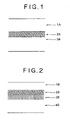
- FIG. 1 An example of the optical information recording medium according to the 10th feature of the invention is shown in Fig. 1 (schematic cross sectional view).
- a substrate 3A, a recording film (hereinafter also referred to as a recording layer) 2A, and a protective film hereinafter also referred to as a protective layer) 1A are provided from the side of the substrate.
- the thickness for the recording film is preferably from 5 to 50 nm. In view of the increase in the transmission light, decrease in the reflectivity and decrease in the heat capacity due to reduction of the film thickness, it is more preferred that the thickness for the recording film is 10 nm or more and 40 nm or less.
- the protective layer is preferably made of a transparent resin and such transparent resin includes, for example, polycarbonate, acryl resin, epoxy resin, and urethane resin.
- the polycarbonate resin is particularly preferred in view of the fabricability and the optical characteristics.
- a polycarbonate is used at 0.6 nm thickness for DVD and at 1.2 nm thickness for CD, this is not particularly limited and, in view of the moldability or the strength, it is preferably 0.05 mm or more and 1.5 mm or less.
- a transparent resin such as a polycarbonate resin or acryl resin is preferred.
- the transparent protective layer may be provided by two layers.
- the recording film since the recording film also has a function as a reflective film, it is desired that also the reflectivity is controlled appropriately.
- FIG. 2 An example of an optical information recording medium according to the 11th feature cf the invention is shown in Fig. 2 (schematic cross sectional view).
- a substrate 4B, a reflective film or heat conditioning film 3B, a recording layer 2B, and a protective layer 1B are provided from the side of the substrate.
- the recording layer is put between the substrate and the protective film, heat can not be dissipated to bring about a worry of increasing the damage to the substrate or making it difficult for sharp recording since heat tends to be diffused on the film surface.
- the diffusion of heat in the direction of the film surface is suppressed by the provision of the heat controlling layer and damages to the substrate due to excess heat are suppressed.
- a reflective layer is disposed in order to improve the re-productivity.
- the heat conductivity of the heat controlling layer is equal with or less than that of the recording film. This is because the heat is dissipated excessively upon melting the recording film in a case where the heat conductivity of the heat controlling layer is high. Further, it is desirable that the corrosion resistance is favorable.
- the constituent material for the reflective film or the heat controlling film in the optical information recording medium according to the 11th feature of the invention includes, for example, alloys comprising Ag, Al, Cu, Au, etc., and the use of Cu alloy is recommended.
- the Cu alloy those containing one or more of Ti, Cr, Ta, Al, Mg, and Ni totaling 3.0 to 15.0 at% are preferred with a view point of the heat conductivity and with the view point of the corrosion resistance.
- the thickness for the reflective film or the heat control film is preferable 20 to 150 nm.
- the film thickness is particularly preferably from 10 nm to 50 nm with a view point of light transmittance and heat capacity.
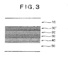
- Fig. 3 An example of the optical information recording medium according to the 12th feature of the invention is shown in Fig. 3 (schematic cross sectional view).
- Dielectric films 3C, 3C are disposed above and below the recording layer 2C.
- a reflective film hereinafter also referred to as a reflective layer
- a heat control film hereinafter also referred to as heat controlling layer 4C is provided below the dielectric film 3C on the side opposite to the incident surface for the laser. That is, the substrate 5C, the reflective film or heat control film 4C, the dielectric film 3C, the recording layer 2C, the dielectric film 3C, and the protective layer 1C are provided from the side of the substrate.
- the dielectric films 3C, 3C are inserted above and below the recording layer 2C in order to suppress the effect of heat by the melting of the recording layer 2C on the substrate 5C or other layers.
- the constituent material for the dielectric film can include, for example, ZnS-SiO 2 , ZnS, SiO 2 , SiN, SiC, etc. ZnS-SiO 2 is particularly preferred with a view point of the optical characteristics and the small heat expansion coefficient.
- the thickness for the dielectric film is preferably 1 nm or more and 200 nm or less. In a case where it is less than 1 nm, no sufficient effect as the dielectric layer can not provided and, on the other hand, in a case where it exceeds 200 nm, this distorts the substrate by the film stress to lose the smoothness of the substrate.
- the thickness of the recording film is preferably from 5 to 50 nm in the same meaning as in the case of the optical information recording medium according to the 10th feature of the invention.
- the thickness of the recording film is more preferably 10 nm or more and 40 nm or less in view of increase in the transmission light, decrease in the reflectivity and decrease in the heat capacity due to reduction of the film thickness.
- the recording film for use in the optical information recording medium according to the third to 9th features of the invention it is preferred to adopt a sputtering method and, in this case, use of the sputtering target according to 17th to 25th features of the invention is recommended as the sputtering target.
- the recording film according to the third feature of the invention can be formed.
- the recording film according to the fourth of the invention can be formed.
- the recording film according to the fifth feature of the invention can be formed.
- the recording film according to the sixth feature of the invention can be formed.
- the recording film according to the 7th feature of the invention can be formed.
- the recording film according to the 8th feature of the invention can be formed.
- the recording film according to the 9th feature of the invention can be formed.
- the content is different between the sputtering target (hereinafter also referred to as a target) and the formed recording film by sputtering.
- a target the sputtering target
- the composition in the target and the composition in the formed film are not identical in the case of Bi.
- the composition in the target and the composition in the formed film are identical or substantially identical.
- vapor pressure of Bi is low, the yield of Bi in the target to the film upon deposition of the film by sputtering is lowered.
- the highest attainable temperature was calculated.
- a recording film and a protective film were provided successively on a polycarbonate substrate (substrate comprising polycarbonate) and the thickness of the recording film was 20 nm.
- the constituent material of the recording film was an Al alloy and the light absorptivity of the recording film was set to 30%.
- the laser spot was set to 0.3 ⁇ m diameter.
- the laser irradiation time was 15 ns.
- the heat conductivity of the recording film was changed as a parameter.
- the result of the calculation that is, the highest attainable temperature determined based on the calculation (highest attainable temperature at the center of the laser spot) is shown in Table 1. Further, the highest attainable temperature ratio between the central portion of the laser spot and a portion spaced apart by 0.3 ⁇ m from the central portion [the highest attainable temperature determined by the calculation (highest attainable temperature at the central portion of the laser spot)/ highest attainable temperature at a position spaced by 0.3 ⁇ m from the central portion of the laser spot] was determined, which was shown as a heat interference ratio in table 1.
- the heat analysis simulation was conducted to calculate the highest attainable temperature.
- a recording film and a protective film are present in this order above a polycarbonate substrate (substrate comprising polycarbonate) and the thickness of the recording film was 20 nm.
- the constituent material for the recording film was Al alloy and the heat conductivity of the recording film was 0.3 W/Kcm.
- the laser spot was 0,3 ⁇ m diameter.
- the laser irradiation time was 15 ns.
- the light absorptivity of the recording film was changed as the parameter.
- a recording film comprising an Al alloy of 20 nm thickness was formed on a polycarbonate resin substrate (substrate comprising polycarbonate resin) of 0.6 mm thickness and 120 mm diameter.
- the composition of the recording film constituent material Al alloy, etc. were controlled such that the heat conductivity of the recording film was from 0.05 to 1.0 W/Kcm.
- the recording film was formed by sputtering by using a sputtering target comprising an Al alloy.
- the composition of the recording film was measured by ICP mass analysis.
- the heat conductivity of the recording film was determined being converted from the specific resistivity of the recording film (thin film) according to the Wiedermann Franz's rule.
- a thin film on a glass substrate of 100 nm thickness was used, the resistivity was measured by a 4-probe electrical resistance measuring device, and the sheet resistance was determined to calculate the specific resistivity.
- the reflectivity of the recording film was determined by measuring the absolute reflectivity of the recording layer formed on the polycarbonate resin substrate by using a visible-UV spectrophotometer (V-570 manufactured by JASCO Co.).
- the light absorptivity (%) of the recording film was calculated by using the equation: 100-[reflectivity (%) + transmittance (%)].
- the transmittance (%) was determined by measuring the sample for which the reflectivity was measured by using the visible lay-UV spectrophotometer described above.
- the melting temperature of the recording film was measured by peeling an Al alley film deposited to 1 ⁇ m thickness from the substrate and collected in an amount of about 5 mg by using a differential thermal analyzer and it was calculated as a mean value of the temperature for starting melting and the temperature at the end of melting.
- the recording mark was formed (recorded) to the thus formed recording film.
- the laser power at the film surface was 10 mW and the speed was 5 m/s.
- a semiconductor laser at a wave length of 405 nm was used as a light source and the laser spot size was set to 0.8 ⁇ m diameter. The laser light was irradiated on the side of the recording film.
- the shape of the mark after the recording was observed by an optical microscope and the ratio of the mark forming area (melting are) (S 2 ) relative to the laser irradiation area (S 1 ) was determined by the calculation based on image processing analysis. It was evaluated in view of the area ratio as failure in a case where the area ratio [(S 2 l S 1 ] ⁇ 100] was less than 20%, as excellent in a case where it is from 20 to 90% (20% or more and 90% or less) and as fair (inferior to excellent but superior to failure, being within an allowable range) in a case where it exceeds 90%, and they were defined as the index for the recording performance.
- the heat conductivity, the reflectivity, the light absorptivity, and the melting temperature of the film were determined by the same manner as that in the case of Example 3. Further, recording marks were formed (recorded) to each of the films by the same method as that in the case of Example 3, the ratio of the mark forming area (S 2 ) relative to the laser irradiation area (S 1 ) was determined as an area ratio [(S 2/ S 1 ) ⁇ 100] and this was used as an index of the recording performance. The evaluation standard for the area ratio was identical with that in Example 3.
- the reflectivity (reflectivity at a wavelength of 405 nm) was measured and corrosion resistance was evaluated by the lowering amount of the reflectivity at the wavelength of 405 nm before and after 95 hr's retention. The result is shown in Table 4.
- Al film or Al alloy film of 20 nm thickness was formed on a polycarbonate substrate of 0.6 mm thickness and 120 mm diameter by sputtering.
- Al alloy film Al-Sn alloy film, Al-Sn-Nd alloy film, or Al-Sn-Y alloy film was formed.
- the Nd content in the Al-Sn-Nd alloy film was changed.
- the heat conductivity, the reflectivity, the light absorptivity, and the melting temperature of the film were determined by the same manner as that in the case of Example 3. Further, recording marks were formed (recorded) to each of the films by the same method as that in the case of Example 3, the ratio of the mark forming area (S 2 ) relative to the laser irradiation area (S 1 ) was determined as an area ratio [(S 2 /S 1 ) ⁇ 100] and this was used as an index of the recording performance. The evaluation standard for the area ratio was identical with that in Example 3.
- Al-Sn alloy with addition of Nd or Y in an amount of 1.0 to 20 at% had an area ratio [(S 2 /S 1 ) ⁇ 100] as the index of the recording performance being evaluated as excellent (20 to 90%) in which good recording mark could be formed.
- Al-Sn(30 at%)-Nd(0.5 at%) alloy film had the area ratio [(S 2 /S 1 ) ⁇ 100] as the index for recording performance being evaluated as excellent but the degree of lowering the heat conductivity was small.
- Al-Sn(30 at%)-Nd(30 at%) alloy film had an excessively high melting temperature and the area ratio [(S 2 /S 1 ) ⁇ 100] as the index for recording performance was evaluated as failure (less than 20%) showing poor recording performance.
- the addition amount of Nd or Y to the Al-Sn alloy is preferably from 1.0 to 20 at%.
- the reflectivity (light reflectivity) is as shown in Table 5. This is the initial reflectivity at the wavelength of 405 nm.
- Al film or Al alloy film of 20 nm thickness was formed on a polycarbonate substrate of 0.6 mm thickness and 120 mm diameter by sputtering.
- Al alloy film Al-Sn alloy film, Al-Sn-Nd-Ta alloy film, Al-Sn-Nd-Ti alloy film, or Al-Sn-Nd-Cr alloy film was formed.
- the Ta content in the Al-Sn-Nd-Ta alloy film was changed.
- the heat conductivity, the light absorptivity, the melting temperature, and the reflectivity (initial reflectivity at a wavelength 405 nm) of the film were determined by the same manner as that in the case of Example 3. Further, recording marks were formed (recorded) to each of the films by the same method as that in the case of Example 3, the ratio of the mark forming area (S 2 ) relative to the laser irradiation area (S 1 ) was determined as an area ratio [(S 2 /S 1 ) ⁇ 100] and this was used as an index of the recording performance. The evaluation standard for the area ratio was identical with that in Example 3.
- the reflectivity (reflectivity at a wavelength of 405 nm) was measured and the lowering amount of the reflectivity at the wavelength of 405 nm before and after 95 hr's retention was determined.
- the melting temperature was excessively high and the area ratio [(S 2 /S 1 ) ⁇ 100] as the index of the recording performance is evaluated as failure (less than 20%) and the recording performance was poor. Accordingly, it can be seen that the addition amount of Ta, Ti, or Cr is preferably from 1.0 to 10.0 at%.
- Al film or Al alloy film of 20 nm thickness was formed on a polycarbonate substrate of 0.6 mm thickness and 120 mm diameter by sputtering.
- Al alloy film Al-Sn-Nd-Ta alloy film, Al-Sn-Nd-Ta-Si alloy film, or Al-Sn-Nd-Ta-Ge alloy film was formed.
- the Si content in the Al-Sn-Nd-Ta-Si alloy film was changed.
- the heat conductivity, the light absorptivity, the melting temperature, and the reflectivity (initial reflectivity at a wavelength 405 nm) of the film were determined by the same manner as that in the case of Example 3. Further, recording marks were formed (recorded) to each of the films by the same method as that in the case of Example 3, the ratio of the mark forming area (S 2 ) relative to the laser irradiation area (S 1 ) was determined as an area ratio [(S 2 /S 1 ) ⁇ 100] and this was used as an index of the recording performance. The evaluation standard for the area ratio was identical with that in Example 3.
- an evaluation test for corrosion resistance was conducted. The test was conducted by a method of dipping a film into an aqueous 5% NaCl solution at 35°C to measure anode polarization, determining the pitting generation potential (potential corresponding to current density at 10 ⁇ A/cm 2 ) therefrom, and evaluating the corrosion resistance based thereon.
- the addition amount of Si or Ge is less than 1.0 at%, such an effect is small and, in a case where it exceeds 15.0 at%, the melting temperature increases remarkably and the recording performance was poor. Accordingly, it can be seen that the addition amount of Si or Ge is preferably from 1.0 to 15.0 at%.
- An Ag film or Ag alloy film of 20 nm thickness was formed on a polycarbonate substrate of 0.6 mm thickness and 120 mm diameter by sputtering.
- As the Ag alloy film Ag-Sn alloy film, Ag-In alloy film, Ag-Nd alloy film, Ag-Bi alloy film, or Ag-Sn-Bi alloy film was formed. The Sn content in the Ag-Sn alloy film and the Bi content in the Ag-Sn-Bi alloy film were changed.
- the heat conductivity, the light absorptivity , the melting temperature, and the reflectivity (initial reflectivity at wavelength 405 nm) of the film were determined by the same manner as that in the case of Example 3. Further, recording marks were formed (recorded) to each of the films by the same method as that in the case of Example 3, the ratio of the mark forming area (S 2 ) relative to the laser irradiation area (S 2 ) was determined as an area ratio [(S 2 /S 1 ) ⁇ 100] and this was used as an index of the recording performance. The evaluation standard for the area ratio was identical with that in Example 3.
- the reflectivity (reflectivity at a wavelength of 405 nm) was measured and the lowering amount of the reflectivity at the wavelength of 405 nm before and after 95 hr's retention was determined.
- Ag-Sn(3.0 at%) alloy film had the area ratio [(S 2 /S 1 ) ⁇ 100] as the index of the recording performance being evaluated as failure (less than 20%) and poor recording performance.
- the addition amount of Sn, In, Nd, or Bi was less than 30 at%, the effect of decreasing the heat conductivity was small and, on the other hand, in a case where it exceeded 30 at%, the melting point increased remarkably and the characteristics as the recording film could no more be obtained.
- the addition amount of Sn, In, Nd or Bi to Ag is, preferably, from 5 to 30 at %.
- lowering of the reflectivity can be suppressed as described above when the content of one or more of Bi and Sb is defined as 0.01 to 2.0 at%.
- it is less than 0.01 at% it is difficult to obtain the effect of suppressing the lowering of the reflectivity and, when it exceeds 2.0%, the degree of lowering the reflectivity is increased rather.
- the recording film according to the invention not only provides a good performance as the recording film by the laser heat melting recording system (sufficient recording is possible) but also is excellent in the productivity and excellent in the durability (recording retainability), it can be used suitably as the recording film for use in an optical information recording medium and is useful.
Landscapes
- Chemical & Material Sciences (AREA)
- Engineering & Computer Science (AREA)
- Organic Chemistry (AREA)
- Metallurgy (AREA)
- Mechanical Engineering (AREA)
- Materials Engineering (AREA)
- Chemical Kinetics & Catalysis (AREA)
- General Engineering & Computer Science (AREA)
- Microelectronics & Electronic Packaging (AREA)
- Manufacturing & Machinery (AREA)
- Inorganic Chemistry (AREA)
- Optics & Photonics (AREA)
- Physics & Mathematics (AREA)
- Optical Record Carriers And Manufacture Thereof (AREA)
- Manufacturing Optical Record Carriers (AREA)
- Thermal Transfer Or Thermal Recording In General (AREA)
- Physical Vapour Deposition (AREA)
Applications Claiming Priority (3)
| Application Number | Priority Date | Filing Date | Title |
|---|---|---|---|
| JP2005030788 | 2005-02-07 | ||
| JP2005355012A JP2006240289A (ja) | 2005-02-07 | 2005-12-08 | 光情報記録媒体用記録膜および光情報記録媒体ならびにスパッタリングターゲット |
| EP06000736A EP1703504B1 (de) | 2005-02-07 | 2006-01-13 | Aufzeichnungsschicht für optische Aufzeichnungsmedien und Sputtertarget |
Related Parent Applications (1)
| Application Number | Title | Priority Date | Filing Date |
|---|---|---|---|
| EP06000736A Division EP1703504B1 (de) | 2005-02-07 | 2006-01-13 | Aufzeichnungsschicht für optische Aufzeichnungsmedien und Sputtertarget |
Publications (1)
| Publication Number | Publication Date |
|---|---|
| EP1978516A1 true EP1978516A1 (de) | 2008-10-08 |
Family
ID=35985205
Family Applications (2)
| Application Number | Title | Priority Date | Filing Date |
|---|---|---|---|
| EP08013027A Withdrawn EP1978516A1 (de) | 2005-02-07 | 2006-01-13 | Aufzeichnungsfilm zum Einsatz in einem optischen Informationsaufzeichnungsmedium, optisches Informationsaufzeichnungsmedium und Sputtertarget |
| EP06000736A Not-in-force EP1703504B1 (de) | 2005-02-07 | 2006-01-13 | Aufzeichnungsschicht für optische Aufzeichnungsmedien und Sputtertarget |
Family Applications After (1)
| Application Number | Title | Priority Date | Filing Date |
|---|---|---|---|
| EP06000736A Not-in-force EP1703504B1 (de) | 2005-02-07 | 2006-01-13 | Aufzeichnungsschicht für optische Aufzeichnungsmedien und Sputtertarget |
Country Status (8)
| Country | Link |
|---|---|
| US (1) | US20060177768A1 (de) |
| EP (2) | EP1978516A1 (de) |
| JP (1) | JP2006240289A (de) |
| KR (2) | KR100793518B1 (de) |
| AT (1) | ATE434255T1 (de) |
| DE (1) | DE602006007256D1 (de) |
| SG (1) | SG125192A1 (de) |
| TW (1) | TW200641870A (de) |
Families Citing this family (28)
| Publication number | Priority date | Publication date | Assignee | Title |
|---|---|---|---|---|
| CN1238554C (zh) * | 2002-06-24 | 2006-01-25 | 株式会社钢臂功科研 | 银合金溅射靶及其制造方法 |
| US7514037B2 (en) * | 2002-08-08 | 2009-04-07 | Kobe Steel, Ltd. | AG base alloy thin film and sputtering target for forming AG base alloy thin film |
| JP3993530B2 (ja) * | 2003-05-16 | 2007-10-17 | 株式会社神戸製鋼所 | Ag−Bi系合金スパッタリングターゲットおよびその製造方法 |
| JP2006294195A (ja) * | 2005-04-14 | 2006-10-26 | Kobe Steel Ltd | 光情報記録用Ag合金反射膜、光情報記録媒体および光情報記録用Ag合金反射膜の形成用のAg合金スパッタリングターゲット |
| JP4377877B2 (ja) | 2005-12-21 | 2009-12-02 | ソニー株式会社 | 光情報記録媒体用Ag合金反射膜、光情報記録媒体および光情報記録媒体用Ag合金反射膜の形成用のAg合金スパッタリングターゲット |
| JP2007335061A (ja) * | 2006-05-16 | 2007-12-27 | Sony Corp | 光情報記録媒体とそのBCA(BurstCuttingArea)マーキング方法 |
| US8092889B2 (en) * | 2006-08-28 | 2012-01-10 | Kobe Steel, Ltd. | Silver alloy reflective film for optical information storage media, optical information storage medium, and sputtering target for the deposition of silver alloy reflective film for optical information storage media |
| JP2008117470A (ja) * | 2006-11-02 | 2008-05-22 | Sony Corp | 光情報記録媒体および光情報記録媒体の製造方法、BCA(BurstCuttingArea)マーキング方法 |
| JP4540687B2 (ja) * | 2007-04-13 | 2010-09-08 | 株式会社ソニー・ディスクアンドデジタルソリューションズ | 読み出し専用の光情報記録媒体 |
| JP4694543B2 (ja) * | 2007-08-29 | 2011-06-08 | 株式会社コベルコ科研 | Ag基合金スパッタリングターゲット、およびその製造方法 |
| US8361587B2 (en) | 2007-07-31 | 2013-01-29 | Nbcuniversal Media, Llc | Enhanced security of optical article |
| JP4833942B2 (ja) * | 2007-08-29 | 2011-12-07 | 株式会社コベルコ科研 | Ag基合金スパッタリングターゲット |
| JP2009076129A (ja) * | 2007-09-19 | 2009-04-09 | Kobe Steel Ltd | 読み出し専用の光情報記録媒体 |
| US8229276B2 (en) * | 2007-09-28 | 2012-07-24 | Nbcuniversal Media, Llc | Limited play optical article |
| US8646106B2 (en) * | 2007-09-28 | 2014-02-04 | Nbcuniversal Media, Llc | Limited play optical article |
| JP5046890B2 (ja) * | 2007-11-29 | 2012-10-10 | 株式会社コベルコ科研 | Ag系スパッタリングターゲット |
| US8051441B2 (en) * | 2008-03-31 | 2011-11-01 | Nbcuniversal Media, Llc | Player-readable code on optical media |
| US9514782B2 (en) * | 2008-05-13 | 2016-12-06 | Nbcuniversal Media, Llc | Method and system for activation of an optical article |
| US8097324B2 (en) * | 2008-05-14 | 2012-01-17 | Nbcuniversal Media, Llc | Enhanced security of optical article |
| US8488428B2 (en) | 2008-05-14 | 2013-07-16 | Nbcuniversal Media, Llc | Enhanced security of optical article |
| JP5331420B2 (ja) | 2008-09-11 | 2013-10-30 | 株式会社神戸製鋼所 | 読み出し専用の光情報記録媒体および該光情報記録媒体の半透過反射膜形成用スパッタリングターゲット |
| JP2010225572A (ja) * | 2008-11-10 | 2010-10-07 | Kobe Steel Ltd | 有機elディスプレイ用の反射アノード電極および配線膜 |
| WO2010119888A1 (ja) * | 2009-04-14 | 2010-10-21 | 株式会社神戸製鋼所 | 光情報記録媒体、光情報記録媒体の反射膜形成用スパッタリングターゲット |
| JP2010250888A (ja) * | 2009-04-14 | 2010-11-04 | Kobe Steel Ltd | 光情報記録媒体 |
| JP4783857B2 (ja) * | 2009-04-14 | 2011-09-28 | 株式会社神戸製鋼所 | 光情報記録媒体およびスパッタリングターゲット |
| JP2012027226A (ja) * | 2010-07-23 | 2012-02-09 | Seiko Epson Corp | 干渉フィルター、光モジュール、及び分析装置 |
| EP3168325B1 (de) * | 2015-11-10 | 2022-01-05 | Materion Advanced Materials Germany GmbH | Sputtertarget auf der basis einer silberlegierung |
| CN112752863A (zh) | 2018-10-03 | 2021-05-04 | 三菱综合材料株式会社 | 叠层膜及Ag合金溅射靶 |
Citations (8)
| Publication number | Priority date | Publication date | Assignee | Title |
|---|---|---|---|---|
| JPH07268617A (ja) * | 1994-03-31 | 1995-10-17 | Tdk Corp | Al合金スパッタ用ターゲットおよびその製造方法 |
| JPH07301705A (ja) * | 1994-05-10 | 1995-11-14 | Kobe Steel Ltd | Al合金薄膜およびAl合金薄膜形成用スパッタリングターゲット |
| WO1998009823A1 (fr) | 1996-09-09 | 1998-03-12 | Matsushita Electric Industrial Co., Ltd. | Support d'enregistrement d'informations optiques, procede de fabrication correspondant, et procede et dispositif d'enregistrement et de lecture d'informations optiques |
| US6096438A (en) * | 1997-04-14 | 2000-08-01 | Kabushiki Kaisha Kobe Seiko Sho | A1-N1-Y alloy films for electrodes of semiconductor devices and sputtering targets for depositing the A1-N1-Y alloy films |
| DE10336228A1 (de) * | 2002-08-08 | 2004-04-01 | Kabushiki Kaisha Kobe Seiko Sho (Kobe Steel, Ltd.), Kobe | Dünner Legierungsfilm auf Ag-Basis und Sputtertarget zum Bilden des Films |
| JP2004153145A (ja) | 2002-10-31 | 2004-05-27 | Canon Inc | 半導体パッケージ |
| JP2004158145A (ja) | 2002-11-08 | 2004-06-03 | Tdk Corp | 光記録媒体 |
| WO2004053861A1 (ja) * | 2002-12-10 | 2004-06-24 | Tanaka Kikinzoku Kogyo K.K. | 光記録媒体の反射膜用の銀合金 |
Family Cites Families (25)
| Publication number | Priority date | Publication date | Assignee | Title |
|---|---|---|---|---|
| JPS6240333A (ja) * | 1985-08-14 | 1987-02-21 | Victor Co Of Japan Ltd | 記録媒体用銀合金 |
| DE3885937T2 (de) * | 1987-05-30 | 1994-06-01 | Kuraray Co | Medium für optische Aufzeichnung und das Medium verwendendes Aufzeichnungsverfahren. |
| US5075145A (en) * | 1989-04-07 | 1991-12-24 | Fuji Photo Film Co., Ltd. | Optical recording medium |
| JPH0512710A (ja) * | 1991-07-03 | 1993-01-22 | Hitachi Maxell Ltd | 光情報記録媒体 |
| EP0474311A1 (de) * | 1990-09-06 | 1992-03-11 | Hitachi Maxell Ltd. | Optischer Aufzeichnungsträger für Daten, Verfahren zum Schreiben und Lesen von Daten und Vorrichtung zum Aufzeichnen von Daten |
| JPH05169819A (ja) * | 1990-09-06 | 1993-07-09 | Hitachi Maxell Ltd | 光情報記録媒体及び情報の記録再生方法並びに情報記録装置 |
| US5948497A (en) * | 1992-10-19 | 1999-09-07 | Eastman Kodak Company | High stability silver based alloy reflectors for use in a writable compact disk |
| US6007889A (en) * | 1998-06-22 | 1999-12-28 | Target Technology, Llc | Metal alloys for the reflective or the semi-reflective layer of an optical storage medium |
| US6544616B2 (en) * | 2000-07-21 | 2003-04-08 | Target Technology Company, Llc | Metal alloys for the reflective or the semi-reflective layer of an optical storage medium |
| SG116432A1 (en) * | 2000-12-26 | 2005-11-28 | Kobe Steel Ltd | Reflective layer or semi-transparent reflective layer for use in optical information recording media, optical information recording media and sputtering target for use in the optical information recording media. |
| JP4783525B2 (ja) * | 2001-08-31 | 2011-09-28 | 株式会社アルバック | 薄膜アルミニウム合金及び薄膜アルミニウム合金形成用スパッタリングターゲット |
| KR100491931B1 (ko) * | 2002-01-25 | 2005-05-30 | 가부시키가이샤 고베 세이코쇼 | 반사 필름, 반사형 액정 표시소자 및 상기 반사 필름을형성하기 위한 스퍼터링 타겟 |
| JP4193408B2 (ja) * | 2002-04-22 | 2008-12-10 | ソニー株式会社 | 光記録媒体及びその製造方法、光記録方法、光再生方法 |
| CN1221962C (zh) * | 2002-04-26 | 2005-10-05 | Tdk股份有限公司 | 光记录介质和在其中对数据进行光记录的方法 |
| CN1238554C (zh) * | 2002-06-24 | 2006-01-25 | 株式会社钢臂功科研 | 银合金溅射靶及其制造方法 |
| US20040038080A1 (en) * | 2002-07-01 | 2004-02-26 | Tdk Corporation | Optical recording medium and method for recording data in the same |
| CN100430215C (zh) * | 2003-04-18 | 2008-11-05 | 目标技术有限公司 | 光学存储介质反射层或半反射层用金属合金 |
| JP4009564B2 (ja) * | 2003-06-27 | 2007-11-14 | 株式会社神戸製鋼所 | リフレクター用Ag合金反射膜、及び、このAg合金反射膜を用いたリフレクター、並びに、このAg合金反射膜のAg合金薄膜の形成用のAg合金スパッタリングターゲット |
| JP2005029849A (ja) * | 2003-07-07 | 2005-02-03 | Kobe Steel Ltd | リフレクター用Ag合金反射膜、及び、このAg合金反射膜を用いたリフレクター、並びに、このAg合金反射膜の形成用のAg合金スパッタリングターゲット |
| JP2005044397A (ja) * | 2003-07-23 | 2005-02-17 | Tdk Corp | 光情報記録媒体 |
| JP2005071408A (ja) * | 2003-08-25 | 2005-03-17 | Tdk Corp | 光情報記録媒体 |
| US20050112019A1 (en) * | 2003-10-30 | 2005-05-26 | Kabushiki Kaisha Kobe Seiko Sho(Kobe Steel, Ltd.) | Aluminum-alloy reflection film for optical information-recording, optical information-recording medium, and aluminum-alloy sputtering target for formation of the aluminum-alloy reflection film for optical information-recording |
| US20050153162A1 (en) * | 2003-12-04 | 2005-07-14 | Kabushiki Kaisha Kobe Seiko Sho (Kobe Steel, Ltd.) | Ag-base interconnecting film for flat panel display, Ag-base sputtering target and flat panel display |
| TWI325134B (en) * | 2004-04-21 | 2010-05-21 | Kobe Steel Ltd | Semi-reflective film and reflective film for optical information recording medium, optical information recording medium, and sputtering target |
| ATE379836T1 (de) * | 2004-06-29 | 2007-12-15 | Kobe Steel Ltd | Halbreflektierende und reflektierende schicht für ein optisches informationsaufzeichnungsmedium, informationsaufzeichnungsmedium, und sputter target |
-
2005
- 2005-12-08 JP JP2005355012A patent/JP2006240289A/ja active Pending
-
2006
- 2006-01-13 EP EP08013027A patent/EP1978516A1/de not_active Withdrawn
- 2006-01-13 AT AT06000736T patent/ATE434255T1/de not_active IP Right Cessation
- 2006-01-13 DE DE602006007256T patent/DE602006007256D1/de active Active
- 2006-01-13 EP EP06000736A patent/EP1703504B1/de not_active Not-in-force
- 2006-01-17 TW TW095101768A patent/TW200641870A/zh unknown
- 2006-01-18 US US11/333,492 patent/US20060177768A1/en not_active Abandoned
- 2006-02-06 SG SG200600753A patent/SG125192A1/en unknown
- 2006-02-07 KR KR1020060011643A patent/KR100793518B1/ko not_active IP Right Cessation
-
2007
- 2007-07-26 KR KR1020070075027A patent/KR100822561B1/ko not_active IP Right Cessation
Patent Citations (9)
| Publication number | Priority date | Publication date | Assignee | Title |
|---|---|---|---|---|
| JPH07268617A (ja) * | 1994-03-31 | 1995-10-17 | Tdk Corp | Al合金スパッタ用ターゲットおよびその製造方法 |
| JPH07301705A (ja) * | 1994-05-10 | 1995-11-14 | Kobe Steel Ltd | Al合金薄膜およびAl合金薄膜形成用スパッタリングターゲット |
| WO1998009823A1 (fr) | 1996-09-09 | 1998-03-12 | Matsushita Electric Industrial Co., Ltd. | Support d'enregistrement d'informations optiques, procede de fabrication correspondant, et procede et dispositif d'enregistrement et de lecture d'informations optiques |
| JP3638152B2 (ja) | 1996-09-09 | 2005-04-13 | 松下電器産業株式会社 | 光学的情報記録媒体とその製造方法、光学的情報記録・再生方法及び光学的情報記録・再生装置 |
| US6096438A (en) * | 1997-04-14 | 2000-08-01 | Kabushiki Kaisha Kobe Seiko Sho | A1-N1-Y alloy films for electrodes of semiconductor devices and sputtering targets for depositing the A1-N1-Y alloy films |
| DE10336228A1 (de) * | 2002-08-08 | 2004-04-01 | Kabushiki Kaisha Kobe Seiko Sho (Kobe Steel, Ltd.), Kobe | Dünner Legierungsfilm auf Ag-Basis und Sputtertarget zum Bilden des Films |
| JP2004153145A (ja) | 2002-10-31 | 2004-05-27 | Canon Inc | 半導体パッケージ |
| JP2004158145A (ja) | 2002-11-08 | 2004-06-03 | Tdk Corp | 光記録媒体 |
| WO2004053861A1 (ja) * | 2002-12-10 | 2004-06-24 | Tanaka Kikinzoku Kogyo K.K. | 光記録媒体の反射膜用の銀合金 |
Non-Patent Citations (1)
| Title |
|---|
| PATENT ABSTRACTS OF JAPAN vol. 1996, no. 02 29 February 1996 (1996-02-29) * |
Also Published As
| Publication number | Publication date |
|---|---|
| KR20060090190A (ko) | 2006-08-10 |
| DE602006007256D1 (de) | 2009-07-30 |
| EP1703504A1 (de) | 2006-09-20 |
| JP2006240289A (ja) | 2006-09-14 |
| EP1703504B1 (de) | 2009-06-17 |
| TW200641870A (en) | 2006-12-01 |
| KR20070080260A (ko) | 2007-08-09 |
| SG125192A1 (en) | 2006-09-29 |
| KR100822561B1 (ko) | 2008-04-16 |
| ATE434255T1 (de) | 2009-07-15 |
| KR100793518B1 (ko) | 2008-01-14 |
| US20060177768A1 (en) | 2006-08-10 |
Similar Documents
| Publication | Publication Date | Title |
|---|---|---|
| EP1703504B1 (de) | Aufzeichnungsschicht für optische Aufzeichnungsmedien und Sputtertarget | |
| EP1617427B1 (de) | Reflexionsschicht aus einer Silberlegierung, Sputter Target dafür, und optischer Datenträger mit einer solchen Schicht | |
| EP1528119B1 (de) | Sputtertarget aus einer Aluminiumlegierung, und reflektierender Film. | |
| US7754307B2 (en) | Silver alloy reflective films for optical information recording media, silver alloy sputtering targets therefor, and optical information recording media | |
| US7695792B2 (en) | Silver alloy reflective films for optical information recording media, silver alloy sputtering targets therefor, and optical information recording media | |
| AU742907B2 (en) | Metal alloys for the reflective or the semi-reflective layer of an optical storage medium | |
| EP1746591B1 (de) | Spiegelschichten aus Silberlegierung für ein optisches Aufzeichnungsmedium, Zerstäubungskathoden aus Silberlegierung hierfür und optisches Aufzeichnungsmedium | |
| EP1746180A1 (de) | Optisches Informationsaufzeichnungsmedium und Silberreflektionsschicht | |
| JP2006054032A5 (de) | ||
| CN100452205C (zh) | 光学信息记录介质中使用的记录膜、光学信息记录介质以及溅射靶 | |
| JP3924308B2 (ja) | レーザーマーキング用再生専用光情報記録媒体用Ag合金反射膜の形成用のAg合金スパッタリングターゲット | |
| JP2005158236A (ja) | 光情報記録用Al合金反射膜、光情報記録媒体および光情報記録用Al合金反射膜の形成用のAl合金スパッタリングターゲット | |
| JP2001357559A (ja) | 光情報記録媒体用反射層、光情報記録媒体及び光情報記録媒体の反射層用スパッタリングターゲット |
Legal Events
| Date | Code | Title | Description |
|---|---|---|---|
| PUAI | Public reference made under article 153(3) epc to a published international application that has entered the european phase |
Free format text: ORIGINAL CODE: 0009012 |
|
| AC | Divisional application: reference to earlier application |
Ref document number: 1703504 Country of ref document: EP Kind code of ref document: P |
|
| AK | Designated contracting states |
Kind code of ref document: A1 Designated state(s): AT BE BG CH CY CZ DE DK EE ES FI FR GB GR HU IE IS IT LI LT LU LV MC NL PL PT RO SE SI SK TR |
|
| 17P | Request for examination filed |
Effective date: 20081023 |
|
| 17Q | First examination report despatched |
Effective date: 20081201 |
|
| AKX | Designation fees paid |
Designated state(s): AT BE BG CH CY CZ DE DK EE ES FI FR GB GR HU IE IS IT LI LT LU LV MC NL PL PT RO SE SI SK TR |
|
| STAA | Information on the status of an ep patent application or granted ep patent |
Free format text: STATUS: THE APPLICATION IS DEEMED TO BE WITHDRAWN |
|
| 18D | Application deemed to be withdrawn |
Effective date: 20090612 |