EP1978293B1 - Verfahren und System zum dreidimensionalen Ausleuchten - Google Patents
Verfahren und System zum dreidimensionalen Ausleuchten Download PDFInfo
- Publication number
- EP1978293B1 EP1978293B1 EP08006480.1A EP08006480A EP1978293B1 EP 1978293 B1 EP1978293 B1 EP 1978293B1 EP 08006480 A EP08006480 A EP 08006480A EP 1978293 B1 EP1978293 B1 EP 1978293B1
- Authority
- EP
- European Patent Office
- Prior art keywords
- illumination
- elevator
- devices
- section
- led
- Prior art date
- Legal status (The legal status is an assumption and is not a legal conclusion. Google has not performed a legal analysis and makes no representation as to the accuracy of the status listed.)
- Active
Links
- 238000000034 method Methods 0.000 title claims description 38
- 238000005286 illumination Methods 0.000 claims description 265
- 230000033001 locomotion Effects 0.000 claims description 44
- 230000005540 biological transmission Effects 0.000 claims description 30
- 238000004891 communication Methods 0.000 claims description 5
- 238000006073 displacement reaction Methods 0.000 description 8
- 238000012545 processing Methods 0.000 description 8
- 239000004677 Nylon Substances 0.000 description 7
- 229920001778 nylon Polymers 0.000 description 7
- 239000000725 suspension Substances 0.000 description 6
- 244000288377 Saxifraga stolonifera Species 0.000 description 5
- 230000008859 change Effects 0.000 description 5
- 230000004888 barrier function Effects 0.000 description 3
- 238000012544 monitoring process Methods 0.000 description 3
- 230000003068 static effect Effects 0.000 description 3
- 208000036829 Device dislocation Diseases 0.000 description 2
- 238000001514 detection method Methods 0.000 description 2
- 238000010586 diagram Methods 0.000 description 2
- 230000003028 elevating effect Effects 0.000 description 2
- 230000007246 mechanism Effects 0.000 description 2
- 230000002776 aggregation Effects 0.000 description 1
- 238000004220 aggregation Methods 0.000 description 1
- 230000001934 delay Effects 0.000 description 1
- 230000001419 dependent effect Effects 0.000 description 1
- 238000011161 development Methods 0.000 description 1
- 230000000694 effects Effects 0.000 description 1
- 230000002035 prolonged effect Effects 0.000 description 1
- 230000009467 reduction Effects 0.000 description 1
- 238000004804 winding Methods 0.000 description 1
Images


Classifications
-
- F—MECHANICAL ENGINEERING; LIGHTING; HEATING; WEAPONS; BLASTING
- F21—LIGHTING
- F21V—FUNCTIONAL FEATURES OR DETAILS OF LIGHTING DEVICES OR SYSTEMS THEREOF; STRUCTURAL COMBINATIONS OF LIGHTING DEVICES WITH OTHER ARTICLES, NOT OTHERWISE PROVIDED FOR
- F21V21/00—Supporting, suspending, or attaching arrangements for lighting devices; Hand grips
- F21V21/14—Adjustable mountings
- F21V21/15—Adjustable mountings specially adapted for power operation, e.g. by remote control
-
- F—MECHANICAL ENGINEERING; LIGHTING; HEATING; WEAPONS; BLASTING
- F21—LIGHTING
- F21S—NON-PORTABLE LIGHTING DEVICES; SYSTEMS THEREOF; VEHICLE LIGHTING DEVICES SPECIALLY ADAPTED FOR VEHICLE EXTERIORS
- F21S2/00—Systems of lighting devices, not provided for in main groups F21S4/00 - F21S10/00 or F21S19/00, e.g. of modular construction
-
- F—MECHANICAL ENGINEERING; LIGHTING; HEATING; WEAPONS; BLASTING
- F21—LIGHTING
- F21V—FUNCTIONAL FEATURES OR DETAILS OF LIGHTING DEVICES OR SYSTEMS THEREOF; STRUCTURAL COMBINATIONS OF LIGHTING DEVICES WITH OTHER ARTICLES, NOT OTHERWISE PROVIDED FOR
- F21V21/00—Supporting, suspending, or attaching arrangements for lighting devices; Hand grips
- F21V21/36—Hoisting or lowering devices, e.g. for maintenance
- F21V21/38—Hoisting or lowering devices, e.g. for maintenance with a cable
-
- F—MECHANICAL ENGINEERING; LIGHTING; HEATING; WEAPONS; BLASTING
- F21—LIGHTING
- F21V—FUNCTIONAL FEATURES OR DETAILS OF LIGHTING DEVICES OR SYSTEMS THEREOF; STRUCTURAL COMBINATIONS OF LIGHTING DEVICES WITH OTHER ARTICLES, NOT OTHERWISE PROVIDED FOR
- F21V23/00—Arrangement of electric circuit elements in or on lighting devices
- F21V23/04—Arrangement of electric circuit elements in or on lighting devices the elements being switches
-
- F—MECHANICAL ENGINEERING; LIGHTING; HEATING; WEAPONS; BLASTING
- F21—LIGHTING
- F21W—INDEXING SCHEME ASSOCIATED WITH SUBCLASSES F21K, F21L, F21S and F21V, RELATING TO USES OR APPLICATIONS OF LIGHTING DEVICES OR SYSTEMS
- F21W2131/00—Use or application of lighting devices or systems not provided for in codes F21W2102/00-F21W2121/00
- F21W2131/40—Lighting for industrial, commercial, recreational or military use
- F21W2131/406—Lighting for industrial, commercial, recreational or military use for theatres, stages or film studios
-
- F—MECHANICAL ENGINEERING; LIGHTING; HEATING; WEAPONS; BLASTING
- F21—LIGHTING
- F21Y—INDEXING SCHEME ASSOCIATED WITH SUBCLASSES F21K, F21L, F21S and F21V, RELATING TO THE FORM OR THE KIND OF THE LIGHT SOURCES OR OF THE COLOUR OF THE LIGHT EMITTED
- F21Y2115/00—Light-generating elements of semiconductor light sources
- F21Y2115/10—Light-emitting diodes [LED]
Definitions
- the present invention relates to a method and a system for three-dimensionally staging. More specifically, the present invention relates to a three-dimensional staging method and system, providing a three-dimensional representation in a theater, a concert hall, a TV studio or others by individually moving a plurality of illumination devices up and down.
- stage representation system wherein a plurality of illumination devices for lighting players and a stage setting including large props or stage properties are suspended from a ceiling of a theater, a concert hall, a TV studio or others, and moved up and down.
- stage representation system as moving the plurality of illumination devices up and down, there is one having an elevation baton suspending the plurality of illumination devices therefrom and capable of moving up and down.
- a stage representation system having an elevation baton free from the above-mentioned drawback is disclosed in Japanese Patent Application Publication Laid-Open No. Hei 8-148005 , wherein a movable portion of an elevator device is divided into two sections; a main elevator section movable up and down along a distance up to the vicinity of a floor, and a one-point suspension displacement elevator section for moving an illumination device by a short pole; so that the displacement elevator section is miniaturized, and further the elevator device is arranged by using a planar baton so that the illumination device is two-dimensionally movable by the two-dimensional movement of the planar baton.
- the three-dimensional stage representation is provided by the one-point suspension displacement elevator in a theater, a concert hall or a TV studio, however, there is a problem in that, since a height of the illumination device moved downward by the one-point suspension displacement elevator is fixed, it is impossible to provide the three-dimensional representation wherein the plurality of illumination devices are independently moved up and down.
- the illumination is represented by using the one-point suspension elevator when the three-dimensional representation is provided in a theater, a concert hall or a TV studio, even if the height of the illumination device moved down by the one-point suspension displacement elevator is not fixed, the displacement distance due to the short pole of the one-point suspension displacement elevator is too short to provide the three-dimensional representation for moving the plurality of illumination devices independently from each other.
- FR-A-2 643 134 discloses a remote-controlled lighting device comprising a motor for controlling a vertical movement of the lighting device and means for controlling the brightness of the lighting device, wherein the means for controlling the brightness and the motor are integrally formed in the lighting device.
- EP-A-0 862 082 relates to a multi-projection system using plural projectors in which the arrangement and the size of images can be freely changed and each image can be freely flown.
- DE 20 57 484 A1 relates to an arrangement for operating light sources.
- An object of the present invention is to provide a three-dimensional stage representation method and system for moving a plurality of illumination devices independently from each other, free from the above-mentioned drawbacks of the prior art.
- a three-dimensional stage representation system used for performing the three-dimensional stage representation.
- the system comprises a plurality of elevator devices, each of the plurality of elevator devices including: a motor, a reel coupled to the motor, and an up-down motion control means for driving the motor to operate the reel; a plurality of illumination devices having the same number as the a plurality of elevator devices, each of the a plurality of illumination devices coupled to the corresponding one of the a plurality of elevator devices by a reel wire, and each of the a plurality of illumination devices including: an LED, and an illumination control means for operating the LED; and a control device including: a device control means for identifying a device to be operated by an input containing information on length of the reel wire from the elevator device to the illumination device coupled to each other as well as brightness of the LED and generating an indication signal to the device to be operated, and a transmission/reception means for transmitting the indication signal generated by the device control means to the device to be operated if the device to be operated
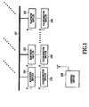
- Fig. 1 illustrates a configuration of a three-dimensional stage representation system according to the present invention.
- the three-dimensional stage representation system according to this embodiment includes elevator devices 101, 102 and 103 for moving illumination devices up and down, illumination devices 104, 105 and 106 having LEDs and connected to the elevator devices 101, 102 and 103, respectively, by reel wires such as nylon guts, a planar baton 107 for suspending the elevator devices 101, 102 and 104 therefrom, and a control device 108 connected to the elevator devices 101, 102 and 103 and the illumination devices 104, 10 5 and 106 via wireless means to be capable of operating the elevator devices 101, 102 and 103 and the illumination devices 104, 105 and 106 independently from each other.
- elevator devices 101, 102 and 103 for moving illumination devices up and down
- illumination devices 104, 105 and 106 having LEDs and connected to the elevator devices 101, 102 and 103, respectively, by reel wires such as nylon guts
- a planar baton 107 for suspend
- the elevator devices 101, 102 and 103, the illumination devices 104, 105 and 106, and the control device 108 have antennas, respectively.
- the independent one-to-one wireless connection can be accomplished by the respective antenna between the control device 108 and each of the elevator devices 101, 102 and 103 and the illumination devices 104, 105 and 106.
- the control device 108 it is possible to individually send an indication signal to the elevator device 101 to descend the illumination device 104.
- the control device 108 it is possible to individually send an indication signal to the illumination device 104 without the intervention of the elevator device 101 to switch on/ off an LED.
- a method may be possible wherein, instead of establishing the one-to-one connection between the illumination device 104 and the control device 108, the elevator device 101 is connected to the illumination device 104 so that the illumination device 104 is operable by the control device 108 via the elevator device 101. In this method, however, a communication section for the illumination device 104 is necessary in the elevator device 101. Further, if the elevator device 101 and the illumination device 104 are connected by a wired connection, a connection cord or others becomes necessary between the elevator device 101 and the illumination device 104 in addition to the reel wire such as nylon guts.
- the three-dimensional stage representation system according to this embodiment is not necessary to use the conventional short pole between the elevator device 101 and the illumination device 104, but may use reel wires such as nylon guts, whereby the displacement distance accompanied with the up-down movement between the elevator device 101 and the illumination device 104 can be prolonged.
- acoustic equipment such as a speaker or a set containing large props or stage properties may be adopted so that the three-dimensional stage representation different from that employing the illumination device can be accomplished.
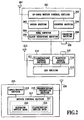
- FIG. 2 is a block diagram illustrating a three-dimensional stage representation system according to one embodiment of the present invention.
- An elevator device 201 in the three-dimensional stage representation system according to this embodiment includes an up-down motion control section 202 for controlling the respective parts, a motor section 203 connected an input/output part of the up-down motion control section 202 for supplying power thereto, a reel section 204 connected to the motor section 203 for winding/unwinding reel wires such as nylon guts, a slack detecting section 205 connected to the reel section 204 for detecting slack of the reel wires such as nylon guts wound/unwound by the reel section 204, a counter section 206 connected to the input/output part of the up-down motion control section and the output of the reel section 204 for monitoring length of the reel wire such as nylon gut, an antenna section 207 connected to the input/output part of the up-down motion control section 202 for communicating with a control device 216, a charging section 208 for charging an
- the illumination device 210 of the three-dimensional stage representation system includes an illumination control section 211 for controlling the respective parts, an LED section 212 connected to the input/output part of the illumination control section 211 and illuminated, an antenna section 213 for communicating with the control device 216, an electric source section 214 for supplying electric power to the illumination control section 211 and the LED section 212, and a connector section 215 connected to the electric source section 214 and detachable/attachable relative to the connector section of the opposed device.
- the control device 216 of the three-dimensional stage representation system includes a device control section 217 for generating indication signals to target devices and, respectively, controlling the elevator device and the illumination device to be operated, an input/output part 218 connected to the input/output part of the device control section 217 for providing a user interface, a transmission/reception section 219 for transmitting/receiving signals relative to/from the elevator device and the illumination device to be operated, and an antenna section 220 connected to the input/output part of the transmission/reception section 219 for communicating with the elevator device and the illumination device to be operated.
- the device control section 217 has a memory 221 for storing data.
- the memory 221 stores elevator device data 222 containing data of the respective elevator devices, and illumination device data 223 containing data of the respective illumination devices.
- the three-dimensional stage representation system wherein a plurality of illumination devices are independently movable up and down to exhibit the three-dimensional stage representation. Then, after describing a processing of each device in the three-dimensional stage representation system, operations of the elevator device and the illumination device in the three-dimensional stage representation system according to this embodiment will be explained when operations of the elevator device and the illumination device have been preliminarily programmed.
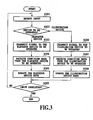
- Fig. 3 is a flow chart illustrating a method relating to a processing of the control device of the three-dimensional stage representation system according to this embodiment of the present invention.
- the control device is input from external such as an operator, the input is detected by the input/output part of the control device at S301.
- the device control section of the control device identifies a device to be operated from the input detected by the input/output part of control device, and generates an indication signal to the device to be operated. If the device to be operated identified at S302 is the elevator device, the method proceeds to S303.
- the illumination device is moved down by lowering the reel wire due to the input from the external such as the operator so that length L of the connected reel wire from the elevator device to the illumination device coupled to each other is "3 m”.
- the operation of the elevator device to be operated will be described below with reference to Fig. 4 . Further, it is assumed that the illumination device normally moves down, for example, by an operation of the elevator device to be operated.
- condition data is transmitted to the control device by the elevator device to be operated, showing that the lowering of the illumination device has been completed by the elevator device to be operated while defining the length L of the reel wire from the elevator device to the illumination device coupled to each other at "3 m".
- the transmission/reception section of the control device receives the condition data transmitted from the elevator device to be operated via the antenna section of the control device.
- the device control section of the control device stores the condition data received by the transmission/reception section of the control device in the memory and updates the elevator device data stored in the memory.
- the method proceeds to S306. For example, it is assumed that the LED is lit at a predetermined brightness by an input from the external such as the operator. Then, at S306, the device control section of the control device generates an indication signal for indicating that the LED is lit in a color having the predetermined brightness (for example, represented by RGB or HSL) by the input detected by the input/output section of the control device, and transmits a signal for transmitting the generated indication signal to the illumination device to be operated to the transmission/reception section of the control device. The transmission/reception section of the control device receiving the signal transmitted from the device control section of the control device transmits the indication signal to the illumination device to be operated via the antenna section of the control device in accordance with the received signal.
- the predetermined brightness for example, represented by RGB or HSL
- the illumination device to be operated receiving the indication signal transmitted from the transmission/reception section of the control device performs an operation for lighting the LED since the content of the received indication signal commands the lighting of the LED.
- the operation of the illumination device to be operated will be described below with reference to Fig. 5 . Further, it is assumed, for example, that the LED normally lit by the operation of the illumination device to be operated.
- condition data representing that the operation for lighting the LED has been completed in the illumination device to be operated is transmitted to the control device.
- the transmission/reception section of the control device receives the condition data transmitted from the illumination device to be operated via the antenna section of the control device.
- the device control section of the control device stores the condition data received by the transmission/reception section of the control device in the memory and updates the illumination device data stored in the memory.
- the device control section of the control device transmits an output signal representing the operation-completion condition and the LED-lighting condition of the illumination device to be operated to the input/output part of the control device in accordance with the condition data stored in the memory.
- the input/output part of the control device receiving the output signal transmitted from the device control section outputs information representing the operation-completion condition of the illumination device to be operated as well as the LED-lighting condition to the external such as the operator.
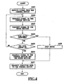
- Fig. 4 is a flow chart representing a method relating to a processing of the elevator device in the three-dimensional stage representation system according to this embodiment of the present invention.
- the up-down motion control section of the elevator device receives the indication signal from the control device via the antenna section of the elevator device at S401.
- the content of the indication signal received from the control device is to lower the illumination device by descending the reel wire so that the length of the reel wire from the elevator device to the illumination device connected thereto becomes "3 m".
- the up-down motion control section of the elevator device receiving the indication signal from the control device transmits a signal that the length of the reel wire to be monitored is "3 m" to the counter section of the elevator device in accordance with the indication signal received from the control device.
- the counter section of the elevator device receiving the signal from the up-down motion control section of the elevator device starts a monitoring operation whether or not the length of the reel wire is "3 m" in accordance with the signal received from the up-down motion control section of the elevator device.
- the up-down motion control section of the elevator device transmits a signal that a power is supplied to the reel section to the motor section of the elevator device in accordance with the signal received from the control device.
- the motor section of the elevator device receiving the signal from the up-down motion control section of the elevator device starts an operation for supplying the power to the reel section in accordance with the signal received from the up-down motion control section of the elevator device.
- the reel section of the elevator device starts a reel-out operation of the reel wire
- the slack detecting section of the elevator device starts a detection of slack of the reel wire.
- the up-down motion control section of the elevator device determines whether or not the slack detecting section of the elevator device detects the slack of the reel wire reeled out from the reel section of the elevator device.
- the method proceeds to S405.
- the up-down motion control section of the elevator device determines whether or not the length of the reel wire monitored by the counter section of the elevator device is "3 m”. If the length of the reel wire monitored by the counter section of the elevator device is "3 m" at S405, the method proceeds to S406.
- the up-down motion control section of the elevator device transmits signals for finishing operations of the counter section and the motor section of the elevator device, respectively, to the counter section and the motor section of the elevator device.
- the counter section and the motor section of the elevator device receiving the signals for finishing the operations thereof finish the operations, respectively.
- the operations of the reel section and the slack detecting section of the elevator device are completed, respectively.
- the up-down motion control section of the elevator device transmits, via the antenna section of the elevator device to the control device, condition data of the elevator device representing that the operation for descending the illumination device has been completed while defining the length L of the reel wire from the elevator device to the illumination device at "3 m".
- the method proceeds to S408.
- the up-down motion control section of the elevator device disrupts an operation of the motor section of the operating elevator device to stop the operations of the reel section and the slack detecting section of the operating elevator device, respectively.
- the method proceeds to S407 at which the up-down motion control section of the elevator device transmits, via the antenna section of the elevator device to the control device, condition data of the elevator device representing that the reel section of the elevator device is abnormally made to stop.
- the method goes back to S402 and the method is continued.
- the indication signal represents that the length of the reel wire from the elevator device to the illumination device coupled to each other is "3 m" in this example
- the indication signal may represent length of the reel wire along which the illumination device is moved up or down in another example.
- the operation of the motor section of the elevator device is made to stop by the up-down motion control section of the elevator device so that the operations of the reel section and the slack detecting section are interrupted, respectively.
- the power supplied from the motor section may be cut off from the reel section by a mechanism of the reel section itself to stop the operations of the reel section and the slack detecting section of the elevator device, respectively.
- Fig. 5 is a flow chart illustrating a method relating to a processing of the illumination device in the three-dimensional stage representation system according to this embodiment of the present invention.
- the illumination control section of the illumination device receives the indication signal from the control device via the antenna section of the illumination device at S501.
- the content of the indication signal from the control device is that the LED is made to light in a color of a predetermined brightness (for example, represented by RGB or HLS).
- the illumination control section of the illumination device receiving the indication signal from the control device transmits a signal to the LED section of the illumination device in accordance with the indication signal received from the control device, so that the LED should be lit in the color having the predetermined brightness.
- the LED section receiving the signal from the illumination control section of the illumination device starts an operation for lighting the LED in the color having the predetermined brightness in accordance with the signal received from the illumination control section of the illumination device.
- the illumination control section of the illumination device determines whether or not the LED section of the illumination device has completed the operation for lighting the LED. If the LED section of the illumination device has completed the operation for lighting the LED, the method proceeds to S504. At S504, the illumination control section of the illumination device transmits condition data of the illumination device to the control device via the antenna section of the illumination device, representing the completion of the operation for lighting the LED of the illumination device. On the contrary, if the LED section of the illumination device has not completed the operation for lighting the LED at S503, the method goes back to S502 and the method is continued.
- Fig. 6 is a flow chart illustrating a method for charging the electric source section of the illumination device in the three-dimensional stage representation system according to this embodiment of the present invention.
- the illumination control section of the illumination device determines whether or not the connector section of the illumination device is brought into contact with the connector section of the elevator device at S601. If it is determined at S601 that the connector section of the illumination device is in contact with the connector section of the elevator device, the method proceeds to S602.
- the illumination control section of the illumination device causes the charging section of the elevator device to start a charging operation for the electric source section of the illumination device.
- the illumination control section of the illumination device determines whether or not the charging of the electric source section in the illumination device has been completed. If the answer is affirmative at S603, the method proceeds to S604.
- the illumination control section of the illumination device transmits condition data representing the completion of the charging in the electric source section of the illumination device to the control device via the antenna section of the illumination device.
- the method proceeds to S604.
- the illumination control section of the illumination device transmits condition data of the illumination device representing that the charging of the electric source section in the illumination device has not started, to the control device via the antenna section of the illumination device. If the answer is negative at S603, the method goes back to S602 and the method is continued.
- the charging of the electric source section of the illumination device is started by the illumination control section of the illumination device.
- the charging section of the elevator device it may be possible to start the charging of the electric source section of the illumination device through the charging section of the elevator device by a mechanism of the electric source section of the illumination device itself.
- the input/output part 218 of the control device 108 detects the input from the operator (S301).
- the up-down motion control section 202 of the elevator device 101 receives the indication signal from the control device 108 via the antenna section 207 of the elevator device 101 (S401).
- the up-down motion control section 202 of the elevator device 101 transmits a signal that the length of the reel wire to be monitored is "3 m" to the counter section 206 of the elevator device 101 in accordance with the indication signal received from the control device 108 (S402).
- the counter section 206 of the elevator device 101 starts monitoring in accordance with the signal received from the up-down motion control section 202 of the elevator device 101 whether or not the length of the reel wire is "3 m".
- the up-down motion control section 202 of the elevator device 101 transmits a signal for supplying a power to the reel section 204 to the motor section 203 of the elevator device 101 in accordance with the indication signal received from the control device 108 (S403).
- the motor section 203 of the elevator device 101 starts the power supply to the reel section 204 in accordance with the signal received from the control device 108.
- the reel section 204 starts unwinding the reel wire and the slack detecting section 205 starts detecting slack of the reel wire.
- the up-down motion control section 202 of the elevator device 101 determines whether or not the slack detecting section 205 of the elevator device 101 detects the slack of the reel wire represented in the reel section 204 of the elevator device 101 (S404). If the answer is negative, the up-down motion control section 202 of the elevator device 101 determines whether or not the length of the reel wire monitored by the counter section 206 of the elevator device 101 is equal to "3 m" (S405).
- the up-down motion control section 202 of the elevator device 101 transmits signals for finishing operations of the counter section 206 and the motor section 203 of the elevator device 101 to the counter section 206 and the motor section 203 of the elevator device 101, respectively (S406).
- the counter section 206 and the motor section 203 of the elevator device 101 receiving the signals for finishing the operations thereof complete the operations thereof.
- the up-down motion control section 202 of the elevator device 101 transmits condition data of the elevator device 101 representing that the length L of the reel wire from the elevator device 101 to the illumination device 104 coupled to each other becomes "3 m" and the operation for descending the illumination device has been completed to the control device 108 via the antenna section 207 of the elevator device 101 (S407).
- the transmission/reception section 219 of the control device 108 receives the condition data transmitted from the elevator device 101, via the antenna section 220 of the control device 108 (S304).
- the device control section 217 of the control device 108 stores the condition data received by the transmission/reception section 219 of the control device 108 in the memory 221 and updates the elevator device data 222 stored in the memory 221 (S305).
- the device control section 217 of the control device 108 outputs information to the input/output part 218 of the control device 108, that the operation of the elevator device 101 has completed and the length L of the reel wire from the elevator device 101 to the illumination device 104 coupled to each other is "3 m" in accordance with the condition data stored in the memory 221.
- the operator recognizes by the output of the condition of the elevator device 101 that the illumination device 104 moves down whereby the length L of the reel wire from the elevator device 101 to the illumination device 104 coupled to each other becomes "3 m".
- the operator inputs a command that the LED of the illumination device 104 should be lit in a color having the predetermined brightness.
- the input/output part 218 of the control device 108 detects the input from the operator (S301).
- the device control section 217 of the control device 108 identifies a device to be operated by the detected input (S302). Since the identified device to be operated is the illumination device 104, the device control section 217 of the control device 108 transmits an indication signal to the illumination device 104 via the transmission/reception section 219 and the antenna section 220 of the control device 108, representing that the LED of the illumination device 104 should be lit in a color having the predetermined brightness (for example, represented by RGB or HLS) (S306).
- the predetermined brightness for example, represented by RGB or HLS
- the illumination control section 211 of the illumination device 104 receives the indication signal from the control device 108 via the antenna section 213 of the illumination device 104 (S501).
- the illumination control section 211 of the illumination device 104 transmits a signal to the LED section 212 of the illumination device 104 in accordance with the indication signal received from the control device 108, representing that the LED should be lit in a color having the predetermined brightness (for example, represented by RGB or HLS) (S502).
- the LED section 212 of the illumination device 104 begins to light the LED in a color having the predetermined brightness in accordance with the signal received from the illumination control section 211 of the illumination device 104.
- the illumination control section 211 of the illumination device 104 determines whether or not the LED section 212 of the illumination device 104 has completed the operation for lighting the LED (S503). If the answer is affirmative, the illumination control section 211 of the illumination device 104 transmits condition data of the illumination device 104 to the control device 108 via the antenna section 213 of the illumination device 104, representing that the operation for lighting the LED of the illumination device 104 has been completed (S504).
- the transmission/reception section 219 of the control device 108 receives, via the antenna section 220 of the control device 108, the condition data transmitted from the illumination device 104 (S307).
- the device control section 217 of the control device 108 stores the condition data received by the transmission/reception section 219 of the control device 108 in the memory 221 and updates the illumination device data 223 stored in the memory 221 (S308).
- the device control section 217 of the control device 108 causes the input/output part 218 of the control device 108 to output information representing the completion of the operation of the illumination device 104 and the LED lighting condition of the illumination device 104 in accordance with the condition data stored in the memory 221. The operator recognizes that the LED of the illumination device 104 has been lit by the output of the condition of the illumination device 104.
- control device 108 is used for descending the illumination device 104 by the elevator device 101 to make the length L of the reel wire from the elevator device to the illumination device coupled to each other to be "3 m", after which the LED is lit by the illumination device 104.
- control device 108 on the elevator device 101 and the operation of the control device 108 on the illumination device 104 are independent from each other, it is possible either to descend the illumination device 104 by the elevator device 101 after the LED is turned on by the illumination device 104 to define the length L of the reel wire from the elevator device to the illumination device coupled to each other at "3 m", or descend or elevate the illumination device 104 by the elevator device 101 simultaneously with turning the LED on/off by the illumination device 104.
- an operator operates the control device to independently descend or elevate a plurality of illumination devices.
- the preliminary programming in the device control section of the control device it is possible to form an imaginary object on a stage, for example, when viewing from audience seats in a theater or others.
- an arch type gate is supposed as an imaginary object on the stage. If LEDs are arranged on a line corresponding to a contour of the gate, the object could be formed by the aggregation of discrete points.
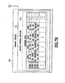
- the operation of the three-dimensional stage representation system for forming the imaginary object by the preliminary programming of actions of the elevator devices and the illumination devices will be described below with reference to Fig. 7A and B .
- FIG. 7A and B is a configuration view illustrating an example of the three-dimensional stage representation system for displaying an imaginary object according to one embodiment of the present invention.
- a concrete example of the three-dimensional stage representation system according to this embodiment includes a planar baton 701 for suspending devices, elevator devices 702 to 705 for moving illumination devices up and down, illumination devices 706 to 709 having LEDs, respectively, and coupled to the elevator devices 702 to 705 by reel wires such as nylon guts, and an control device 710 wirelessly coupled to the elevator devices 702 to 705 and the illumination devices 706 to 709 and programmed to be capable of independently operating the elevator devices 702 to 705 and the illumination devices 706 to 709.
- the control device 710 includes a device control section 711.
- the device control section 711 stores program data 712.
- the program data 712 stored in the device control section 711 has information on the respective LEDs of the illumination devices 706 to 709 variable with time in relation to length L of the reel wire from the elevator device to the illumination device coupled to each other as well as brightness.
- the information on the length L corresponds to a height of a contour line of an imaginary object (such as an arch type gate) on a stage.
- the information on the brightness of the LED relates to the on-off operation or brightness/darkness in color.
- the brightness/darkness in color can be represented by using RGB or HLS.
- the brightness of LED becomes brighter in the order of dark, turned-on and bright.
- the program data 712 stored in the device control section 711 has the information on the respective LEDs in all the illumination devices variable with time regarding the length L of the reel wire from the elevator device to the illumination device coupled to each other as well as the brightness in color all over the period in which the stage representation is performed.
- an imaginary object for example, an arch type gate
- the light emission of the LED it is possible to vary the illumination, for example, in accordance with the motion of a player passing through the gate.
- the program data 712 has the information on the time, the length L of the reel wire from the elevator device to the illumination device coupled to each other and the color brightness, since all the elevator devices used in this embodiment move the illumination devices at the same speed, there may be a case where motion of a certain illumination device delays at a predetermined time whereby it does not reaches the aimed position. Accordingly, in the three-dimensional stage representation system according to this embodiment, the illumination device is controlled by using the length L of the reel wire from the elevator device to the illumination device coupled to each other as a main parameter, while using the time as a secondary parameter.
- control device receives condition data representing the completion of the operation of the elevator device from the elevator device and stores the condition data in the memory shown in Fig. 2 (not shown in Fig. 7B ), and thereafter, transmits an indication signal to the elevator device so that the next length L of the reel wire is obtained and then transmits an indication signal to the illumination device.
- the control device after receiving the condition data representing the completion of the operation of the elevator device from the elevator device and storing the condition data in the memory shown in Fig. 2 (not shown in Fig. 7B ), the control device first transmits the indication signal to the elevator device and then to the illumination device.
- the order of the transmission of the indication signals to the elevator device and the illumination device may be reversed or simultaneous.
- the delay of up-down motion of the illumination device is prevented by changing the up-down motion speed of the respective elevator device, it may be possible to control the illumination device by using the time as a main parameter.
- the device control section 711 of the control device 710 in the example of the three-dimensional stage representation system according to this embodiment independently operates the elevator devices 702 to 705 and the illumination devices 706 to 709 in the concrete example of the three-dimensional stage representation system according to this embodiment in accordance with the stored program data 712, in the same manner as the method programmed in relation to the operation of the control device in the three-dimensional stage representation system described above with reference to Fig. 3 , based on the information contained in the program data 712 relating to the length L of the respective reel wire and the brightness in color.
- the device control section of the control device generates an indication signal transmitted to a device to be operated, based on the input from external such as an operator detected by the input/output part of the control device.
- the device control section 711 of the control device 710 in the example of the three-dimensional stage representation system according to this embodiment does not generate the indication signal to the device to be operated by the detection of the input from the external such as the operator by means of the input/output part of the control device, but generates the indication signal to the device to be operated in accordance with the stored program data 712.
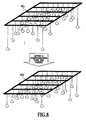
- An example in relation to the variation of an imaginary object with time represented by the three-dimensional stage representation system while programming the operations of the elevator devices and the illumination devices in the device control section 711 of the control device 710 will be described below with reference to Fig. 8 .
- Fig. 8 is a configuration view illustrating an example relating to the change of an imaginary object with time, represented by the three-dimensional stage representation system according to this embodiment of the present invention.
- the elevator devices and the control device are not shown for the purpose of simplicity.
- the three-dimensional stage representation system provides a three-dimensional effect by moving the illumination devices up and down without displacing the planar baton.
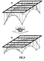
- FIG. 9 is a configuration view illustrating another example relating to the change of an imaginary object with time, represented by the three-dimensional stage representation system according to this embodiment of the present invention.
- the elevator devices and the control device are not shown for the purpose of simplicity.
- a static three-dimensional object representing a levitating magic carpet at two different times according to the three-dimensional stage representation system of this embodiment.
- the contour of outer edge of the carpet is shown by a solid line and the broken line.
- the elevator devices and the illumination devices are operated respectively so that the LEDs are arranged on the contour line, whereby the static three-dimensional object of the magic carpet is formed in a state shown in a planar baton 901.
- the control device operates the elevator devices and the illumination devices to arrange the LEDs again on the contour line based on the program data such as shown in Fig. 7B , another static three-dimensional object of the magic carpet is formed in a state shown in a planner baton 902. Thereby, it is possible to move the LEDs corresponding to the edge of the carpet up and down as if the carpet were fluttered by wind.
- the form of the magic carpet by the three-dimensional stage representation system according to this embodiment is variable with time as if it were levitating in air as seen from any viewing angle, like the representation, for example, by computer graphic.
- the magic carpet shown in this example is a mere illustration wherein an imaginary object not actually existing is formed as seen in any viewing angle by using an actual object (such as an animal or landscape) and dynamically variable with time.
- the elevator device, the illumination device and the control device are wirelessly connected to each other, connection cords for the control are unnecessary between the elevator device and the illumination, whereby the reduction in size and weight is possible, and a number of illumination devices are simultaneously movable up and down as well as a number of LEDs are simultaneously turned on/off.
- a system is applicable not only to the three-dimensional stage representation in a theater, concert hall or TV studio, but also to a case where it is necessary for independently moving up and down a set including a plurality of illumination devices.
- An example not forming part of the present invention may adapt. acoustic equipments such as speakers, large props or stage properties.
Landscapes
- Engineering & Computer Science (AREA)
- General Engineering & Computer Science (AREA)
- Circuit Arrangement For Electric Light Sources In General (AREA)
- Indicating And Signalling Devices For Elevators (AREA)
- Non-Portable Lighting Devices Or Systems Thereof (AREA)
Claims (4)
- Dreidimensionales Bühnendarstellungsverfahren, das zur Durchführung einer dreidimensionalen Bühnendarstellung verwendet wird, bei dem ein Bühnendarstellungssystem eine Steuerungsvorrichtung (108, 216), eine Mehrzahl von Aufzugvorrichtungen (101, 102, 103, 201) und eine Mehrzahl von Beleuchtungsvorrichtungen (104, 105, 106, 210) aufweist, die Steuerungsvorrichtung (216) ein Vorrichtungssteuerungsmittel (217), ein Eingabe/Ausgabe-Mittel (218) und ein Sende/Empfangs-Mittel (219) aufweist, jede von der Mehrzahl von Aufzugvorrichtungen (201) ein Aufwärts-Abwärts-Bewegungssteuerungsmittel (202), einen Motor (203) und einen Aufroller (204), der mit dem Motor (203) gekoppelt ist, aufweist, jede von der Mehrzahl von Beleuchtungsvorrichtungen (104, 105, 106, 210) ein Beleuchtungssteuerungsmittel (211) und eine LED (212) aufweist, die Anzahl an Aufzugvorrichtungen (101, 102, 103, 201) gleich der Anzahl von Beleuchtungsvorrichtungen (104, 105, 106, 210) ist und jede von den Beleuchtungsvorrichtungen (104, 105, 106, 210) mit einer entsprechenden der Aufzugvorrichtungen (101, 102, 103, 201) durch einen Aufrollerdraht gekoppelt ist, bei dem das Verfahren die Schritte aufweist:(a) Identifizieren einer zu betreibenden Vorrichtung durch das Vorrichtungssteuerungsmittel (217) in der Steuerungsvorrichtung (216) von einer Eingabe, die Information über die Länge des Aufrollerdrahts von der Aufzugvorrichtung (201) zu der Beleuchtungsvorrichtung (210), die miteinander gekoppelt sind, sowie über die Helligkeit der LED aufweist, und Erzeugen eines Anzeigesignals für die zu betreibende Vorrichtung;(b) wenn die zu betreibende Vorrichtung, die durch das Vorrichtungssteuerungsmittel (217) der Steuerungsvorrichtung (216) identifiziert wird, die Aufzugvorrichtung (201) ist, Senden des Anzeigesignals, das von dem Vorrichtungssteuerungsmittel (217) der Steuerungsvorrichtung (216) erzeugt worden ist, an die zu betreibende Aufzugvorrichtung (201) durch das Sende/Empfangs-Mittel (219) der Steuerungsvorrichtung (216);(c) bei Empfang des Anzeigesignals, das von dem Sende/Empfangs-Mittel (219) der Steuerungsvorrichtung (217) gesendet worden ist, Senden des Inhalts des empfangenen Anzeigesignals an den Motor (203) der zu betreibenden Aufzugvorrichtung (201) durch das Aufwärts-Abwärts-Bewegungssteuerungsmittel (202) der Aufzugvorrichtung (201), wodurch der Motor (203) der Aufzugvorrichtung (201) betrieben wird, um den Aufroller (204) der Aufzugvorrichtung (201) derart zu bewegen, dass die Länge des Aufrollerdrahts von der Aufzugvorrichtung (201) zu der Beleuchtungsvorrichtung (210), die miteinander gekoppelt sind, gleich der eingegebenen Länge des Aufrollerdrahts wird;(d) wenn die zu betreibende Vorrichtung, die von dem Vorrichtungssteuerungsmittel (217) der Steuerungsvorrichtung (116) identifiziert wird, die Beleuchtungsvorrichtung (210) ist, Senden des Anzeigesignals, das von dem Vorrichtungssteuerungsmittel (217) der Steuerungsvorrichtung (216) erzeugt wird, an die zu betreibende Beleuchtungsvorrichtung (210) durch das Sende/Empfangs-Mittel (219) der Steuerungsvorrichtung (216);(e) bei Empfang des Anzeigesignals, das von dem Sende/Empfangs-Mittel (219) der Steuerungsvorrichtung (216) gesendet wird, Senden des Inhalts des empfangenen Anzeigesignals an die LED (212) der zu betreibenden Beleuchtungsvorrichtung (104, 105, 106, 210) durch das Beleuchtungssteuerungsmittel (211) der Beleuchtungsvorrichtung (210)" wodurch die LED bezüglich der Helligkeit der LED basierend auf der eingegebenen Information betrieben wird;(f) Abhängen der Aufzugvorrichtungen (101, 102, 104, 201) von einer Stabebene (107) derart, dass ein dreidimensionales Objekt gebildet wird, indem als Ergebnis der Durchführung der Schritte (c) und (e) für jede von der Mehrzahl von Aufzugvorrichtungen (101, 102, 103, 201) alle LEDs (212) und jede von der Mehrzahl von Beleuchtungsvorrichtungen (104, 105, 106, 210) verwendet werden; und(g) Bilden eines dynamischen dreidimensionalen Objekts, indem alle LEDs als Ergebnis der wiederholten Durchführung der Schritte (a) bis (f) verwendet werden,wobei die Eingabe Programmdaten sind, die zeitlich variable Information über die Länge des Aufrollerdrahts von der Aufzugvorrichtung (101, 102, 103, 201) zu der Beleuchtungsvorrichtung (104, 105, 106, 210), die miteinander gekoppelt sind, und über die Helligkeit der LED (212) aufweisen, bezüglich jeder von der Mehrzahl von Aufzugvorrichtungen (101, 102, 103, 201) und jeder von der Mehrzahl von Beleuchtungsvorrichtungen (210).
- Dreidimensionales Bühnendarstellungssystem, das verwendet wird zur Durchführung einer dreidimensionalen Bühnendarstellung, wobei das System aufweist:eine Mehrzahl von Aufzugvorrichtungen (101, 102, 103, 201), wobei jede von der Mehrzahl von Aufzugvorrichtungen (101, 102, 103, 201) aufweist:einen Motor (203),einen Aufroller, der mit dem Motor (203) gekoppelt ist, undein Aufwärts-Abwärts-Bewegungssteuerungsmittel (202) zum Antreiben des Motors zum Betreiben des Aufrollers;eine Mehrzahl von Beleuchtungsvorrichtungen (104, 105, 106, 210) in gleicher Anzahl wie die Mehrzahl von Aufzugvorrichtungen (101, 102, 103, 201), wobei jede von der Mehrzahl von Beleuchtungsvorrichtungen (104, 105, 106, 210) mit der entsprechenden von der Mehrzahl von Aufzugvorrichtungen (101, 102, 103, 201) durch einen Aufrollerdraht gekoppelt ist, und jede von der Mehrzahl von Beleuchtungsvorrichtungen (104, 105, 106, 210) aufweist:eine LED (212), undein Beleuchtungssteuerungsmittel zum Betreiben der LED (212); undeine Steuerungsvorrichtung (108, 216), die aufweist:ein Vorrichtungssteuerungsmittel (217) zum Identifizieren einer zu betreibenden Vorrichtung durch eine Eingabe, die Information über die Länge des Aufrollerdrahts von der Aufzugvorrichtung (101, 102, 103, 201) zu der Beleuchtungsvorrichtung (104, 105, 106, 210), die miteinander gekoppelt sind, sowie über die Helligkeit der LED aufweist, und zum Erzeugen eines Anzeigesignals für die zu betreibende Vorrichtung, undein Sende/Empfangs-Mittel (219) zum Senden des Anzeigesignals, das von dem Vorrichtungssteuerungsmittel (217) erzeugt worden ist, an die zu betreibende Vorrichtung, wenn die zu betreibende Vorrichtung, die von dem Vorrichtungssteuerungsmittel (217) identifiziert wird, die Aufzugvorrichtung oder die Beleuchtungsvorrichtung ist;bei dem das Aufwärts-Abwärts-Bewegungssteuerungsmittel (202) der Aufzugvorrichtung das Anzeigesignal empfängt, das von dem Sende/Empfangs-Mittel der Steuerungsvorrichtung gesendet worden ist, und den Inhalt des empfangenen Anzeigesignals an den Motor (203) sendet, um den Aufroller (204) derart zu betreiben, dass die Länge des Aufrollerdrahts von der Aufzugvorrichtung (101, 102, 103, 201) zu der Beleuchtungsvorrichtung (104, 105, 106, 210), die miteinander gekoppelt sind, gleich der eingegebenen Länge des Aufrollerdrahts wird;bei dem das Beleuchtungssteuerungsmittel der Beleuchtungsvorrichtung (104, 105, 106, 210) das Anzeigesignal empfängt, das von dem Sende/Empfangs-Mittel (219) der Steuerungsvorrichtung (216) gesendet worden ist, und den Inhalt des empfangenen Anzeigesignals an die LED (212) sendet, um die LED der Beleuchtungsvorrichtung (104, 105, 106, 210) basierend auf der eingegebenen Information bezüglich der Helligkeit der LED zu betreiben;wobei das dreidimensionale Bühnendarstellungssystem ferner einen Stab (107) aufweist zum Abhängen der Aufzugsvorrichtungen (101, 102, 104, 201) derart, dassein dreidimensionales Objekt gebildet wird unter Verwendung aller LEDs, als Ergebnis des Betreibens des Motors (203), um den Aufroller durch das Aufwärts-Abwärts-Bewegungssteuerungsmittel (202) der Aufzugvorrichtung (101, 102, 103, 201) zu betreiben, und des Betreibens der LED (212) durch das Beleuchtungssteuerungsmittel der Beleuchtungsvorrichtung (104, 105, 106, 210), in Bezug auf jede von der Mehrzahl von Aufzugvorrichtungen (101, 102, 103, 201) und jede von der Mehrzahl von Beleuchtungsvorrichtungen (104, 105, 106, 210); undein dynamisches dreidimensionales Objekt gebildet wird unter Verwendung aller LEDs (212) durch Wiederholen eines Betriebs, bei dem das Aufwärts-Abwärts-Bewegungssteuerungsmittel (202) der Aufzugvorrichtung (101, 102, 103, 201) den Motor betreibt, um den Aufroller zu betreiben, und das Beleuchtungssteuerungsmittel der Beleuchtungsvorrichtung (104, 105, 106, 210) die LED betreibt, bezüglich jeder von der Mehrzahl von Aufzugvorrichtungen (101, 102, 103, 201) und jeder von der Mehrzahl von Beleuchtungsvorrichtungen (104, 105, 106,210),wobei die Eingabe Programmdaten sind, die zeitlich variable Information über die Länge des Aufrollerdrahts von der Aufzugvorrichtung (101, 102, 103, 201) zu der Beleuchtungsvorrichtung (104, 105, 106, 210), die miteinander gekoppelt sind, und über die Helligkeit der LED (212) aufweisen, bezüglich jeder von der Mehrzahl von Aufzugvorrichtungen (101, 102, 103, 201) und jeder von der Mehrzahl von Beleuchtungsvorrichtungen (104, 105, 106, 210).
- Verfahren nach Anspruch 1, bei dem die Steuerungsvorrichtung, die Mehrzahl von Aufzugvorrichtungen (101, 102, 103, 201) und die Mehrzahl von Beleuchtungsvorrichtungen (104, 105, 106, 210) ferner jeweils ein drahtloses Kommunikationsmittel aufweisen, und
das Anzeigesignal von der Steuerungsvorrichtung über das drahtlose Kommunikationsmittel gesendet wird. - System nach Anspruch 2, bei dem die Steuerungsvorrichtung, die Mehrzahl von Aufzugvorrichtungen (101, 102, 103, 201) und die Mehrzahl von Beleuchtungsvorrichtungen (104, 105, 106, 210) ferner jeweils ein drahtloses Kommunikationsmittel aufweisen, und
das Anzeigesignal von der Steuerungsvorrichtung über das drahtlose Kommunikationsmittel gesendet wird.
Applications Claiming Priority (1)
| Application Number | Priority Date | Filing Date | Title |
|---|---|---|---|
| JP2007097805A JP5173231B2 (ja) | 2007-04-03 | 2007-04-03 | 三次元演出方法およびシステム |
Publications (3)
| Publication Number | Publication Date |
|---|---|
| EP1978293A1 EP1978293A1 (de) | 2008-10-08 |
| EP1978293B1 true EP1978293B1 (de) | 2016-10-05 |
| EP1978293B8 EP1978293B8 (de) | 2017-03-15 |
Family
ID=39592093
Family Applications (1)
| Application Number | Title | Priority Date | Filing Date |
|---|---|---|---|
| EP08006480.1A Active EP1978293B8 (de) | 2007-04-03 | 2008-03-31 | Verfahren und System zum dreidimensionalen Ausleuchten |
Country Status (5)
| Country | Link |
|---|---|
| US (1) | US7918584B2 (de) |
| EP (1) | EP1978293B8 (de) |
| JP (1) | JP5173231B2 (de) |
| CA (1) | CA2627946C (de) |
| DK (1) | DK1978293T3 (de) |
Families Citing this family (11)
| Publication number | Priority date | Publication date | Assignee | Title |
|---|---|---|---|---|
| FI9346U1 (fi) * | 2011-05-27 | 2011-08-17 | Dsign Space Alive Oy | Järjestely tilan muuttamiseksi |
| DE102012205313A1 (de) * | 2012-03-30 | 2013-10-02 | Art + Com Ag | Beleuchtungsvorrichtung und Beleuchtungsverfahren |
| JP2014186842A (ja) * | 2013-03-22 | 2014-10-02 | Toshiba Lighting & Technology Corp | 照明バトン |
| JP5705943B1 (ja) * | 2013-10-18 | 2015-04-22 | 株式会社Isa | 舞台演出装置及び舞台演出方法 |
| JP6066376B1 (ja) * | 2015-08-10 | 2017-01-25 | 株式会社Isa | 舞台演出システム及び舞台演出方法 |
| JP6142374B1 (ja) * | 2016-04-21 | 2017-06-07 | 株式会社Isa | 照明昇降装置 |
| JP6186607B1 (ja) * | 2017-04-13 | 2017-08-30 | 株式会社Isa | 照明昇降装置 |
| JP6371447B1 (ja) | 2017-07-07 | 2018-08-08 | 株式会社Isa | 昇降装置 |
| JP6867032B2 (ja) * | 2017-12-20 | 2021-04-28 | 株式会社Isa | 三次元演出方法、三次元演出システムおよび昇降装置 |
| CA3060781C (en) | 2019-05-28 | 2022-04-26 | Isa Co., Ltd. | Illumination system and illumination method |
| JP6619903B1 (ja) * | 2019-05-28 | 2019-12-11 | 株式会社Isa | 照明システムおよび照明方法 |
Family Cites Families (15)
| Publication number | Priority date | Publication date | Assignee | Title |
|---|---|---|---|---|
| DE2057484A1 (de) | 1970-11-23 | 1972-05-31 | Siemens Ag | Anordnung zum Bedienen von Scheinwerfern |
| JPS62105395A (ja) * | 1985-10-31 | 1987-05-15 | 東芝ライテック株式会社 | 照明制御システム |
| FR2643134B1 (fr) | 1989-02-14 | 1993-06-25 | Philips Eclairage | Dispositif d'eclairage telecommande programmable |
| WO1993003306A1 (de) | 1991-08-02 | 1993-02-18 | Sachtler Ag | Studioleuchte |
| DE9109580U1 (de) | 1991-08-02 | 1991-11-14 | Sachtler AG - Kommunikationstechnik, 85748 Garching | Studioleuchte |
| JPH06140159A (ja) * | 1992-09-10 | 1994-05-20 | Toshiba Lighting & Technol Corp | 照明制御システム |
| JP2588026Y2 (ja) * | 1992-09-14 | 1999-01-06 | 松下電工株式会社 | 可動照明装置 |
| JPH06310284A (ja) * | 1993-04-28 | 1994-11-04 | Toshiba Lighting & Technol Corp | 照明制御装置および照明装置 |
| JPH07176206A (ja) * | 1993-12-20 | 1995-07-14 | Tec Corp | 電動昇降装置 |
| JPH08148005A (ja) * | 1994-11-22 | 1996-06-07 | R D S Kk | 面状バトン装置 |
| JPH09120703A (ja) * | 1995-10-25 | 1997-05-06 | Sanko:Kk | シャンデリア |
| JPH10301202A (ja) | 1997-02-28 | 1998-11-13 | R D S Kk | マルチプロジェクションシステム |
| JP3045075U (ja) * | 1997-07-04 | 1998-01-23 | 瑩寶科技股▲ふん▼有限公司 | 発光ダイオードによる舞台照明装置 |
| JPH11135270A (ja) * | 1997-08-29 | 1999-05-21 | Toshiba Lighting & Technology Corp | アリーナ照明姿勢制御システム |
| JP4944291B2 (ja) * | 2000-09-07 | 2012-05-30 | パナソニック株式会社 | 照明システム |
-
2007
- 2007-04-03 JP JP2007097805A patent/JP5173231B2/ja active Active
-
2008
- 2008-03-31 EP EP08006480.1A patent/EP1978293B8/de active Active
- 2008-03-31 DK DK08006480.1T patent/DK1978293T3/en active
- 2008-04-01 US US12/078,524 patent/US7918584B2/en active Active
- 2008-04-02 CA CA 2627946 patent/CA2627946C/en active Active
Also Published As
| Publication number | Publication date |
|---|---|
| CA2627946C (en) | 2015-04-14 |
| JP2008257961A (ja) | 2008-10-23 |
| US7918584B2 (en) | 2011-04-05 |
| EP1978293B8 (de) | 2017-03-15 |
| CA2627946A1 (en) | 2008-10-03 |
| EP1978293A1 (de) | 2008-10-08 |
| JP5173231B2 (ja) | 2013-04-03 |
| DK1978293T3 (en) | 2017-01-09 |
| US20080247179A1 (en) | 2008-10-09 |
Similar Documents
| Publication | Publication Date | Title |
|---|---|---|
| EP1978293B1 (de) | Verfahren und System zum dreidimensionalen Ausleuchten | |
| CN103415754B (zh) | 用于提供具有预定长度的未卷绕电缆部分的绞盘 | |
| JP6560725B2 (ja) | コミュニケーションロボット及びコミュニケーションシステム | |
| JP6066376B1 (ja) | 舞台演出システム及び舞台演出方法 | |
| KR20190126170A (ko) | 무대연출 시스템 | |
| JP2022047719A (ja) | 作業機械の情報表示装置およびこれを備えた作業機械、作業機械の情報表示方法 | |
| KR102162643B1 (ko) | 팔로우 스팟 조명장치 및 조명방법 | |
| JP7226667B2 (ja) | エレベーターシステム、及びエレベーターの改修方法 | |
| JP5490213B2 (ja) | 演出装置 | |
| JP2021080063A (ja) | 天井クレーン装置の移動操作方法、移動方向表示装置及び移動操作システム | |
| JP4575894B2 (ja) | 照明設備 | |
| KR20150120198A (ko) | 지능형 조명 장치 | |
| KR102599347B1 (ko) | 소형 와이어 기반 촬영 시스템 | |
| JPH0778692A (ja) | 投光照明コントロール装置 | |
| JP4178476B2 (ja) | 多機能バトンシステム | |
| KR100853663B1 (ko) | 엘리베이터의 군관리시스템을 위한 운행승강기 표시장치 | |
| JPH0679070A (ja) | 舞台機構監視装置 | |
| JPH11246180A (ja) | 吊り物システム | |
| HK40007134A (en) | Elevating apparatus | |
| HK1230538A1 (en) | Stage representation system and stage representation method | |
| EP2587896A2 (de) | Beleuchtungssystem und Betriebsverfahren dafür | |
| JPH11102605A (ja) | 照明装置 |
Legal Events
| Date | Code | Title | Description |
|---|---|---|---|
| PUAI | Public reference made under article 153(3) epc to a published international application that has entered the european phase |
Free format text: ORIGINAL CODE: 0009012 |
|
| AK | Designated contracting states |
Kind code of ref document: A1 Designated state(s): AT BE BG CH CY CZ DE DK EE ES FI FR GB GR HR HU IE IS IT LI LT LU LV MC MT NL NO PL PT RO SE SI SK TR |
|
| AX | Request for extension of the european patent |
Extension state: AL BA MK RS |
|
| 17P | Request for examination filed |
Effective date: 20090331 |
|
| 17Q | First examination report despatched |
Effective date: 20090429 |
|
| AKX | Designation fees paid |
Designated state(s): AT BE BG CH CY CZ DE DK EE ES FI FR GB GR HR HU IE IS IT LI LT LU LV MC MT NL NO PL PT RO SE SI SK TR |
|
| RAP1 | Party data changed (applicant data changed or rights of an application transferred) |
Owner name: ISA CO., LTD. |
|
| GRAP | Despatch of communication of intention to grant a patent |
Free format text: ORIGINAL CODE: EPIDOSNIGR1 |
|
| INTG | Intention to grant announced |
Effective date: 20160420 |
|
| GRAS | Grant fee paid |
Free format text: ORIGINAL CODE: EPIDOSNIGR3 |
|
| GRAA | (expected) grant |
Free format text: ORIGINAL CODE: 0009210 |
|
| AK | Designated contracting states |
Kind code of ref document: B1 Designated state(s): AT BE BG CH CY CZ DE DK EE ES FI FR GB GR HR HU IE IS IT LI LT LU LV MC MT NL NO PL PT RO SE SI SK TR |
|
| REG | Reference to a national code |
Ref country code: GB Ref legal event code: FG4D |
|
| REG | Reference to a national code |
Ref country code: CH Ref legal event code: EP |
|
| REG | Reference to a national code |
Ref country code: AT Ref legal event code: REF Ref document number: 834978 Country of ref document: AT Kind code of ref document: T Effective date: 20161015 |
|
| REG | Reference to a national code |
Ref country code: IE Ref legal event code: FG4D |
|
| REG | Reference to a national code |
Ref country code: DE Ref legal event code: R096 Ref document number: 602008046603 Country of ref document: DE |
|
| GRAT | Correction requested after decision to grant or after decision to maintain patent in amended form |
Free format text: ORIGINAL CODE: EPIDOSNCDEC |
|
| RAP2 | Party data changed (patent owner data changed or rights of a patent transferred) |
Owner name: ISA CO., LTD. |
|
| REG | Reference to a national code |
Ref country code: NL Ref legal event code: FP |
|
| REG | Reference to a national code |
Ref country code: DK Ref legal event code: T3 Effective date: 20170102 |
|
| REG | Reference to a national code |
Ref country code: LT Ref legal event code: MG4D |
|
| PG25 | Lapsed in a contracting state [announced via postgrant information from national office to epo] |
Ref country code: LV Free format text: LAPSE BECAUSE OF FAILURE TO SUBMIT A TRANSLATION OF THE DESCRIPTION OR TO PAY THE FEE WITHIN THE PRESCRIBED TIME-LIMIT Effective date: 20161005 |
|
| REG | Reference to a national code |
Ref country code: FR Ref legal event code: PLFP Year of fee payment: 10 |
|
| PG25 | Lapsed in a contracting state [announced via postgrant information from national office to epo] |
Ref country code: LT Free format text: LAPSE BECAUSE OF FAILURE TO SUBMIT A TRANSLATION OF THE DESCRIPTION OR TO PAY THE FEE WITHIN THE PRESCRIBED TIME-LIMIT Effective date: 20161005 Ref country code: NO Free format text: LAPSE BECAUSE OF FAILURE TO SUBMIT A TRANSLATION OF THE DESCRIPTION OR TO PAY THE FEE WITHIN THE PRESCRIBED TIME-LIMIT Effective date: 20170105 Ref country code: GR Free format text: LAPSE BECAUSE OF FAILURE TO SUBMIT A TRANSLATION OF THE DESCRIPTION OR TO PAY THE FEE WITHIN THE PRESCRIBED TIME-LIMIT Effective date: 20170106 Ref country code: SE Free format text: LAPSE BECAUSE OF FAILURE TO SUBMIT A TRANSLATION OF THE DESCRIPTION OR TO PAY THE FEE WITHIN THE PRESCRIBED TIME-LIMIT Effective date: 20161005 |
|
| PG25 | Lapsed in a contracting state [announced via postgrant information from national office to epo] |
Ref country code: PL Free format text: LAPSE BECAUSE OF FAILURE TO SUBMIT A TRANSLATION OF THE DESCRIPTION OR TO PAY THE FEE WITHIN THE PRESCRIBED TIME-LIMIT Effective date: 20161005 Ref country code: HR Free format text: LAPSE BECAUSE OF FAILURE TO SUBMIT A TRANSLATION OF THE DESCRIPTION OR TO PAY THE FEE WITHIN THE PRESCRIBED TIME-LIMIT Effective date: 20161005 Ref country code: PT Free format text: LAPSE BECAUSE OF FAILURE TO SUBMIT A TRANSLATION OF THE DESCRIPTION OR TO PAY THE FEE WITHIN THE PRESCRIBED TIME-LIMIT Effective date: 20170206 Ref country code: IS Free format text: LAPSE BECAUSE OF FAILURE TO SUBMIT A TRANSLATION OF THE DESCRIPTION OR TO PAY THE FEE WITHIN THE PRESCRIBED TIME-LIMIT Effective date: 20170205 Ref country code: ES Free format text: LAPSE BECAUSE OF FAILURE TO SUBMIT A TRANSLATION OF THE DESCRIPTION OR TO PAY THE FEE WITHIN THE PRESCRIBED TIME-LIMIT Effective date: 20161005 Ref country code: FI Free format text: LAPSE BECAUSE OF FAILURE TO SUBMIT A TRANSLATION OF THE DESCRIPTION OR TO PAY THE FEE WITHIN THE PRESCRIBED TIME-LIMIT Effective date: 20161005 |
|
| REG | Reference to a national code |
Ref country code: DE Ref legal event code: R097 Ref document number: 602008046603 Country of ref document: DE |
|
| PG25 | Lapsed in a contracting state [announced via postgrant information from national office to epo] |
Ref country code: RO Free format text: LAPSE BECAUSE OF FAILURE TO SUBMIT A TRANSLATION OF THE DESCRIPTION OR TO PAY THE FEE WITHIN THE PRESCRIBED TIME-LIMIT Effective date: 20161005 Ref country code: CZ Free format text: LAPSE BECAUSE OF FAILURE TO SUBMIT A TRANSLATION OF THE DESCRIPTION OR TO PAY THE FEE WITHIN THE PRESCRIBED TIME-LIMIT Effective date: 20161005 Ref country code: SK Free format text: LAPSE BECAUSE OF FAILURE TO SUBMIT A TRANSLATION OF THE DESCRIPTION OR TO PAY THE FEE WITHIN THE PRESCRIBED TIME-LIMIT Effective date: 20161005 Ref country code: EE Free format text: LAPSE BECAUSE OF FAILURE TO SUBMIT A TRANSLATION OF THE DESCRIPTION OR TO PAY THE FEE WITHIN THE PRESCRIBED TIME-LIMIT Effective date: 20161005 |
|
| PLBE | No opposition filed within time limit |
Free format text: ORIGINAL CODE: 0009261 |
|
| STAA | Information on the status of an ep patent application or granted ep patent |
Free format text: STATUS: NO OPPOSITION FILED WITHIN TIME LIMIT |
|
| PG25 | Lapsed in a contracting state [announced via postgrant information from national office to epo] |
Ref country code: BG Free format text: LAPSE BECAUSE OF FAILURE TO SUBMIT A TRANSLATION OF THE DESCRIPTION OR TO PAY THE FEE WITHIN THE PRESCRIBED TIME-LIMIT Effective date: 20170105 Ref country code: IT Free format text: LAPSE BECAUSE OF FAILURE TO SUBMIT A TRANSLATION OF THE DESCRIPTION OR TO PAY THE FEE WITHIN THE PRESCRIBED TIME-LIMIT Effective date: 20161005 |
|
| 26N | No opposition filed |
Effective date: 20170706 |
|
| REG | Reference to a national code |
Ref country code: CH Ref legal event code: PL |
|
| PG25 | Lapsed in a contracting state [announced via postgrant information from national office to epo] |
Ref country code: SI Free format text: LAPSE BECAUSE OF FAILURE TO SUBMIT A TRANSLATION OF THE DESCRIPTION OR TO PAY THE FEE WITHIN THE PRESCRIBED TIME-LIMIT Effective date: 20161005 Ref country code: MC Free format text: LAPSE BECAUSE OF FAILURE TO SUBMIT A TRANSLATION OF THE DESCRIPTION OR TO PAY THE FEE WITHIN THE PRESCRIBED TIME-LIMIT Effective date: 20161005 |
|
| REG | Reference to a national code |
Ref country code: IE Ref legal event code: MM4A |
|
| PG25 | Lapsed in a contracting state [announced via postgrant information from national office to epo] |
Ref country code: LU Free format text: LAPSE BECAUSE OF NON-PAYMENT OF DUE FEES Effective date: 20170331 |
|
| PG25 | Lapsed in a contracting state [announced via postgrant information from national office to epo] |
Ref country code: IE Free format text: LAPSE BECAUSE OF NON-PAYMENT OF DUE FEES Effective date: 20170331 Ref country code: CH Free format text: LAPSE BECAUSE OF NON-PAYMENT OF DUE FEES Effective date: 20170331 Ref country code: LI Free format text: LAPSE BECAUSE OF NON-PAYMENT OF DUE FEES Effective date: 20170331 |
|
| REG | Reference to a national code |
Ref country code: FR Ref legal event code: PLFP Year of fee payment: 11 |
|
| PG25 | Lapsed in a contracting state [announced via postgrant information from national office to epo] |
Ref country code: MT Free format text: LAPSE BECAUSE OF NON-PAYMENT OF DUE FEES Effective date: 20170331 |
|
| REG | Reference to a national code |
Ref country code: AT Ref legal event code: UEP Ref document number: 834978 Country of ref document: AT Kind code of ref document: T Effective date: 20161005 |
|
| PG25 | Lapsed in a contracting state [announced via postgrant information from national office to epo] |
Ref country code: HU Free format text: LAPSE BECAUSE OF FAILURE TO SUBMIT A TRANSLATION OF THE DESCRIPTION OR TO PAY THE FEE WITHIN THE PRESCRIBED TIME-LIMIT; INVALID AB INITIO Effective date: 20080331 |
|
| PG25 | Lapsed in a contracting state [announced via postgrant information from national office to epo] |
Ref country code: CY Free format text: LAPSE BECAUSE OF NON-PAYMENT OF DUE FEES Effective date: 20161005 |
|
| PG25 | Lapsed in a contracting state [announced via postgrant information from national office to epo] |
Ref country code: TR Free format text: LAPSE BECAUSE OF FAILURE TO SUBMIT A TRANSLATION OF THE DESCRIPTION OR TO PAY THE FEE WITHIN THE PRESCRIBED TIME-LIMIT Effective date: 20161005 |
|
| PGFP | Annual fee paid to national office [announced via postgrant information from national office to epo] |
Ref country code: DE Payment date: 20250307 Year of fee payment: 18 |
|
| PGFP | Annual fee paid to national office [announced via postgrant information from national office to epo] |
Ref country code: NL Payment date: 20250324 Year of fee payment: 18 Ref country code: DK Payment date: 20250321 Year of fee payment: 18 |
|
| PGFP | Annual fee paid to national office [announced via postgrant information from national office to epo] |
Ref country code: AT Payment date: 20250319 Year of fee payment: 18 Ref country code: BE Payment date: 20250320 Year of fee payment: 18 |
|
| PGFP | Annual fee paid to national office [announced via postgrant information from national office to epo] |
Ref country code: FR Payment date: 20250324 Year of fee payment: 18 |
|
| PGFP | Annual fee paid to national office [announced via postgrant information from national office to epo] |
Ref country code: GB Payment date: 20250324 Year of fee payment: 18 |