EP1978281A1 - Verbindungselement für ein Verbindungsglied - Google Patents
Verbindungselement für ein Verbindungsglied Download PDFInfo
- Publication number
- EP1978281A1 EP1978281A1 EP07450066A EP07450066A EP1978281A1 EP 1978281 A1 EP1978281 A1 EP 1978281A1 EP 07450066 A EP07450066 A EP 07450066A EP 07450066 A EP07450066 A EP 07450066A EP 1978281 A1 EP1978281 A1 EP 1978281A1
- Authority
- EP
- European Patent Office
- Prior art keywords
- vee
- bor2
- bor1
- connecting element
- bores
- Prior art date
- Legal status (The legal status is an assumption and is not a legal conclusion. Google has not performed a legal analysis and makes no representation as to the accuracy of the status listed.)
- Granted
Links
- 101100326267 Arabidopsis thaliana BOR2 gene Proteins 0.000 claims abstract description 24
- 101100028962 Saccharomyces cerevisiae (strain ATCC 204508 / S288c) PDR1 gene Proteins 0.000 claims abstract description 24
- 101100073352 Streptomyces halstedii sch1 gene Proteins 0.000 claims abstract description 16
- 101100073357 Streptomyces halstedii sch2 gene Proteins 0.000 claims abstract description 16
- 101100394003 Butyrivibrio fibrisolvens end1 gene Proteins 0.000 claims description 16
- 101100174722 Saccharomyces cerevisiae (strain ATCC 204508 / S288c) GAA1 gene Proteins 0.000 claims description 16
- 101100296979 Saccharomyces cerevisiae (strain ATCC 204508 / S288c) PEP5 gene Proteins 0.000 claims description 16
- 230000001154 acute effect Effects 0.000 claims description 3
- 238000004519 manufacturing process Methods 0.000 description 3
- 238000005452 bending Methods 0.000 description 2
- 230000002349 favourable effect Effects 0.000 description 1
Images

Classifications
-
- F—MECHANICAL ENGINEERING; LIGHTING; HEATING; WEAPONS; BLASTING
- F16—ENGINEERING ELEMENTS AND UNITS; GENERAL MEASURES FOR PRODUCING AND MAINTAINING EFFECTIVE FUNCTIONING OF MACHINES OR INSTALLATIONS; THERMAL INSULATION IN GENERAL
- F16G—BELTS, CABLES, OR ROPES, PREDOMINANTLY USED FOR DRIVING PURPOSES; CHAINS; FITTINGS PREDOMINANTLY USED THEREFOR
- F16G15/00—Chain couplings, Shackles; Chain joints; Chain links; Chain bushes
- F16G15/02—Chain couplings, Shackles; Chain joints; Chain links; Chain bushes for fastening more or less permanently
-
- F—MECHANICAL ENGINEERING; LIGHTING; HEATING; WEAPONS; BLASTING
- F16—ENGINEERING ELEMENTS AND UNITS; GENERAL MEASURES FOR PRODUCING AND MAINTAINING EFFECTIVE FUNCTIONING OF MACHINES OR INSTALLATIONS; THERMAL INSULATION IN GENERAL
- F16G—BELTS, CABLES, OR ROPES, PREDOMINANTLY USED FOR DRIVING PURPOSES; CHAINS; FITTINGS PREDOMINANTLY USED THEREFOR
- F16G13/00—Chains
- F16G13/12—Hauling- or hoisting-chains so called ornamental chains
- F16G13/14—Hauling- or hoisting-chains so called ornamental chains built up from readily-separable links
Definitions
- the invention relates to a connecting element of a connecting member for load-bearing elements, such as chains, hooks od.
- the connecting element has two substantially mutually parallel legs whose free ends each have a bore for receiving a connecting pin, by means of which the connecting element with a similarly formed another connecting element to the connecting member is connectable, wherein the connecting elements are held together only by the connecting pin, and the bores extend in the same direction to each other.
- the invention relates to a connecting member, which has two connecting elements connected by means of a connecting pin.
- Connecting members of the type just mentioned are usually used for connecting chains, lashing means, etc. with each other or with corresponding accessories, such as hooks, shackles, etc.
- a link has become known, which has a first and a second connecting element, each having a vertex portion and extending therefrom parallel leg.
- the end portions of the legs are provided with a bore for receiving a connecting pin, wherein the ends of the first connecting element are covered by the ends of the second connecting element.
- a disadvantage of the known embodiment is, above all, that it is required by design, to use two differently shaped connecting elements, which significantly increase the manufacturing cost.
- the connection pin is subject to design large bending loads, resulting in disadvantages in terms of strength properties.
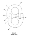
- FIG. 1 A link of the above type, which under the name "Connex” or from the AT 001 926 U1 has become known is in Fig. 1 shown.
- This connecting link VER has two interconnected connecting elements VE1, VE2 with a substantially U-shaped cross section, wherein one end EN1 of a leg SC1 of a connecting element VE1 forms a fork into which one end section EN2 of one leg SC2 of the other connecting element VE2 can be inserted ,
- the end sections EN1, EN2 each have a bore through which a connecting pin VBZ is guided in an assembled state.
- the disadvantage of this link is that it is very expensive in production, since the parts must be forged to achieve the required load capacity.
- the DE 22 00 381 A shows a chain link for making a detachable connection of round link chains.
- the known chain link has two identical link halves, each of which consists of a bracket with an inner leg and an outer leg. The two brackets are held together by teeth of the inner and outer hoops, in addition, a locking pin is provided, which is guided by mutually aligned, obliquely to a longitudinal center plane bores through the inner and outer legs of the limb halves.
- the locking pin does not hold the two limbs together, but only serves to prevent each other from loosening the teeth of the inner and outer hoop.
- the disadvantage of this embodiment is especially that it is relatively expensive to produce due to the teeth of the inner and outer hoop.
- the axis of the bores extends to the longitudinal middle straight of the connecting element at an acute angle which is greater than the angle of friction between the connecting pin and the bores.
- end regions in which the bores are arranged are each of lesser thickness than the section of the connecting element connecting the end regions.
- connection pin connected to the connecting elements are designed according to one of claims 1 to 4.
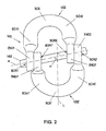
- a connecting element VGL has two connecting elements VEE, VEE ', each with a substantially U-shaped cross section.
- Each connecting element VEE, VEE ' has a vertex SCE, SCE' and two limbs SCH1, SCH2, SCH1 ', SCH2' extending therefrom.
- END1, END2, END1 'END2' of the legs SCH1, SCH2, SCH1 ', SCH2' is a bore BOR1, BOR2, BOR1 ', BOR2' is provided, the bores BOR1, BOR2, BOR1 ', BOR2' a Connecting elements VEE, VEE 'in the same direction to each other.
- the two connecting elements VEE, VEE ' are joined together by means of a connecting pin VBZ to the connecting member VGL.
- the axis a of the bores BOR1, BOR2, BOR1 ', BOR2' extends at an acute angle ⁇ to the longitudinal center line ⁇ of the connecting element VEE or VEE '.
- the angle ⁇ is greater than the angle of friction between the connecting pin VBZ and the holes BOR1, BOR2, BOR1 ', BOR2'.
- the two legs SCH1, SCH2, SCH1 ', SCH2' of each connecting element VEE, VEE ' can have different lengths, the end areas END1, END2, END1', END2 'having a smaller thickness than that between the end areas END1, END2, END1' Section 'END2'.
- the angle ⁇ is just so great that slipping of the connecting elements VEE, VEE 'with respect to the connecting pin VBZ is possible, since this can improve the load distribution to the legs SCH1, SCH2, SCH1', SCH2 '.
- the connecting pin VBZ can be secured against axial slippage by means of a securing element, not shown here, which has one or more securing sleeves comprising the connecting pin VBZ.
- the securing sleeve or the securing sleeves in turn can be secured against slipping along the longitudinal axis a of the connecting pin VBZ by means of a fixing spring mounted in an annular groove running around the connecting pin VBZ.
- connecting pin VBZ can also by means of a cited from the beginning AT 001 926 U1 Toward known fuse element protected against slipping out.
- connecting elements VEE, VEE ' can be manufactured as bent wire parts instead of the forged parts as usual, thereby also resulting in the possibility of recalibration of the connecting elements VEE, VEE'.
- connecting element VEE VEE 'can also form clevises, as known from the prior art ( Fig.1 ) is known, but this is only essential that the connecting pin is inclined.
- the axis a of the bores or of the connecting pin VBZ extends inclined to the longitudinal center line ⁇ of the connecting member VEE 'or VEE.
Landscapes
- Engineering & Computer Science (AREA)
- General Engineering & Computer Science (AREA)
- Mechanical Engineering (AREA)
- Snaps, Bayonet Connections, Set Pins, And Snap Rings (AREA)
- Vehicle Body Suspensions (AREA)
- Transmission Devices (AREA)
- Manipulator (AREA)
Abstract
Description
- Die Erfindung betrifft ein Verbindungselement eines Verbindungsgliedes für lasttragende Elemente, wie Ketten, Haken od. dgl., wobei das Verbindungselement zwei im wesentlichen parallel zueinander verlaufende Schenkel aufweist, deren freie Enden je eine Bohrung zur Aufnahme eines Verbindungszapfens aufweisen, mittels welchem das Verbindungselement mit einem gleichartig ausgebildeten anderen Verbindungselement zu dem Verbindungsglied verbindbar ist, wobei die Verbindungselemente nur durch den Verbindungszapfen zusammengehalten sind, und die Bohrungen gleichsinnig zueinander verlaufen.
- Weiters betrifft die Erfindung ein Verbindungsglied, welches zwei mittels eines Verbindungszapfens verbundene Verbindungselemente aufweist.
- Verbindungsglieder der soeben erwähnten Art werden üblicherweise zur Verbindung von Ketten, Zurrmitteln etc. miteinander bzw. mit entsprechendem Zubehör, wie beispielsweise Haken, Schäkeln etc. verwendet.
- Aus der
EP 009 2382 ist ein Verbindungsglied bekannt geworden, welches ein erstes und ein zweites Verbindungselement aufweist, die je einen Scheitelabschnitt und sich von diesem erstreckende parallele Schenkel aufweisen. Die Endabschnitte der Schenkel sind mit einer Bohrung zur Aufnahme eines Verbindungszapfens ausgestattet, wobei die Enden des ersten Verbindungselementes von den Enden des zweiten Verbindungselement umfasst sind. Nachteilig an der bekannten Ausführungsform ist vor allem, dass es bauartbedingt erforderlich ist, zwei verschiedenartig ausgebildete Verbindungselemente zu verwenden, wodurch sich die Herstellungskosten wesentlich erhöhen. Darüber hinaus ist der Verbindungszapfen bauartbedingt großen Biegebelastungen unterworfen, wodurch sich Nachteile hinsichtlich der Festigkeitseigenschaften ergeben. - Ein Verbindungsglied der oben genannten Art, welches unter der Bezeichnung "Connex" bzw. aus der
AT 001 926 U1 Fig. 1 dargestellt. Dieses Verbindungsglied VER weist zwei miteinander verbundene Verbindungselemente VE1, VE2 mit einem im wesentlichen U-förmigen Querschnitt auf, wobei ein Ende EN1 eines Schenkels SC1 eines Verbindungselements VE1 eine Gabel bildet, in welche ein Endabschnitt EN2 eines Schenkels SC2 des anderen Verbindungselementes VE2 eingeführt werden kann. Die Endabschnitte EN1, EN2 weisen je eine Bohrung auf, durch welche in einem montierten Zustand ein Verbindungszapfen VBZ geführt ist. Nachteilig an diesem Verbindungsglied ist, dass es in der Fertigung sehr aufwendig ist, da die Teile geschmiedet werden müssen, um die geforderte Belastbarkeit zu erreichen. - Die
DE 22 00 381 A zeigt ein Kettenverbindungsglied zum Herstellen einer lösbaren Verbindung von Rundgliederketten. Das bekannte Kettenverbindungsglied weist zwei einander gleiche Gliedhälften auf, von welchen jede aus einem Bügel mit einem Innenschenkel und einem Außenschenkel besteht. Die beiden Bügel sind über Verzahnungen der Innen und Außenbügel zusammen gehalten, wobei zusätzlich ein Sicherungsstift vorgesehen ist, der durch miteinander fluchtende, schräg zu einer Längsmittelebene verlaufende Bohrungen durch die Innen- und Außenschenkel der Gliedhälften geführt ist. Der Sicherungsstift hält jedoch die beiden Gliedhälften nicht zusammen, sondern dient lediglich dazu ein voneinander Lösen der Verzahnungen der Innen- und Außenbügel zu verhindern. Nachteilig an dieser Ausführungsform ist vor allem, dass sie aufgrund der Verzahnungen der Innen- und Außenbügel relativ aufwendig herzustellen ist. - Es ist daher eine Aufgabe der Erfindung, ein Verbindungsglied zu schaffen, welches auf einfache und kostengünstige Weise herzustellen ist und darüber hinaus günstigere Festigkeitseigenschaften aufweist als die bekannten Verbindungsglieder.
- Diese Aufgabe wird mit einem Verbindungselement der eingangs genannten Art erfindungsgemäß dadurch gelöst, dass die Bohrungen zueinander versetzt sind und geneigt zu einer Längsmittelgeraden des Verbindungselements verlaufen.
- Es ist ein Verdienst der Erfindung, ein Verbindungselement zu schaffen, welches mit einem gleichartig ausgebildeten Verbindungselement mittels eines Verbindungszapfens zu einem Verbindungsglied zusammengebaut werden kann, wobei aufgrund des durch die geneigten Bohrungen schrägen Verlaufes des Verbindungszapfens die Biegebelastungen auf den Verbindungszapfen wesentlich verringert werden können.
- In einer bevorzugten Ausführungsform der Erfindung verläuft die Achse der Bohrungen zu der Längsmittelgerade des Verbindungselementes unter einem spitzen Winkel, der größer als der Reibungswinkel zwischen dem Verbindungszapfen und den Bohrungen ist.
- Weitere Vorteile lassen sich dadurch erzielen, dass die Endbereiche, in welchen die Bohrungen angeordnet sind, je von geringerer Dicke sind als der die Endbereiche verbindender Abschnitt des Verbindungselements.
- Die oben genannte Aufgabe kann auch mit einem Verbindungsglied der eingangs genannten Art gelöst werden, bei welchem die des Verbindungszapfens verbundenen Verbindungselemente je nach einem der Ansprüche 1 bis 4 ausgebildet sind.
- Die Erfindung samt weiterer Vorteile wird im Folgenden anhand einiger nicht einschränkender Ausführungsbeispiele näher erläutert, die in der Zeichnung dargestellt sind. In dieser zeigen schematisch:
-
Fig. 2 ein erfindungsgemäßes Verbindungsglied in einer perspektivischen Ansicht und -
Fig. 3 einen Längsschnitt durch das Verbindungsglied ausFig. 2 . - Gemäß
Fig. 2 weist ein erfindungsgemäßes Verbindungsglied VGL zwei Verbindungselemente VEE, VEE' mit je einem im wesentlichen U-förmigen Querschnitt auf. Jedes Verbindungselement VEE, VEE' weist einen Scheitel SCE, SCE' und zwei sich von diesem erstreckende Schenkel SCH1, SCH2, SCH1', SCH2' auf. An jedem freien Enden END1, END2, END1' END2' der Schenkel SCH1, SCH2, SCH1', SCH2' ist eine Bohrung BOR1, BOR2, BOR1', BOR2' vorgesehen, wobei die Bohrungen BOR1, BOR2, BOR1', BOR2' eines Verbindungselemente VEE, VEE' gleichsinnig zueinander verlaufen. Weiters sind die Bohrungen BOR1, BOR2, BOR1', BOR2' eines Verbindungselementes VEE, VEE' in Richtung einer Längsmittelgeraden λ des Verbindungselementes VEE bzw. VEE' bzw. in Längsrichtung seiner Schenkel SCH1, SCH2, SCH1', SCH2' gegeneinander versetzt und verlaufen geneigt zu der Längsmittelgeraden λ. - Die beiden Verbindungselemente VEE, VEE' sind mittels eines Verbindungszapfens VBZ zu dem Verbindungsglied VGL zusammengefügt.
- Die Achse a der Bohrungen BOR1, BOR2, BOR1', BOR2' verläuft unter einem spitzen Winkel α zu der Längsmittelgeraden λ des Verbindungselementes VEE bzw. VEE'. Der Winkel α ist hierbei größer als der Reibungswinkel zwischen dem Verbindungszapfen VBZ und den Bohrungen BOR1, BOR2, BOR1', BOR2'. Die beiden Schenkel SCH1, SCH2, SCH1', SCH2' jedes Verbindungselementes VEE, VEE' können unterschiedlich lang sein, wobei die Endbereiche END1, END2, END1', END2' eine geringere Dicke aufweisen als der zwischen den Endbereichen END1, END2, END1', END2' gelegene Abschnitt. Bevorzugterweise ist der Winkel α gerade so groß, dass ein Rutschen der Verbindungselemente VEE, VEE' gegenüber dem Verbindungszapfen VBZ möglich ist, da sich dadurch die Lastverteilung auf die Schenkel SCH1, SCH2, SCH1', SCH2' verbessern lässt.
- Durch die geneigte Anordnung des Verbindungszapfens VBZ können die Endbereiche END1, END2, END1', END2' der Verbindungselemente VEE, VEE' aufeinander zurutschen, wodurch ein zwischen den Enden END1, END2, END1', END2' der beiden Verbindungselemente VEE, VEE' bei der Montage möglicherweise vorhandener Spalt automatisch geschlossen werden kann, wodurch sich auch die Fertigungstoleranzen bei einem erfindungsgemäßen Verbindungselement gegenüber den bekannten Verbindungselementen bzw. Verbindungsgliedern erhöhen.
- Der Verbindungszapfen VBZ kann mittels eines hier nicht dargestellten Sicherungselementes, welches eine oder mehrere den Verbindungszapfen VBZ umfassende Sicherungshülsen aufweist, gegen ein axiales Verrutschen gesichert sein. Die Sicherungshülse bzw. die Sicherungshülsen ihrerseits können mittels einer in einer um den Verbindungszapfen VBZ laufenden Ringnut gelagerten Fixierfeder gegen ein Verrutschen entlang der Längsachse a des Verbindungszapfens VBZ gesichert sein.
- Der Verbindungszapfen VBZ kann aber auch mittels eines aus der eingangs zitierten
AT 001 926 U1 - Es hat sich herausgestellt, dass durch die erfindungsgemäße Lösung die auf den Verbindungszapfen VBZ wirkenden Belastungen wesentlich verringert werden können. Weiters kann auch die Gesamtfestigkeit des Verbindungsgliedes gegenüber den bekannten Verbindungsgliedern erhöht werden.
- Darüber hinaus ist es von Vorteil, dass die Verbindungselemente VEE, VEE' als Drahtbiegeteile anstatt wie bisher üblich als Schmiedeteile gefertigt werden können, dadurch ergibt sich auch die Möglichkeit einer Nachkalibrierung der Verbindungselemente VEE, VEE'.
- Natürlich können die freien Enden eines Verbindungselementes VEE, VEE' auch Gabelköpfe bilden, wie dies aus dem Stand der Technik (
Fig.1 ) bekannt ist, wesentlich ist hierbei jedoch nur, dass der Verbindungsbolzen schräg verläuft. D. h., dass die Achse a der Bohrungen bzw. des Verbindungszapfens VBZ geneigt zu der Längsmittelgeraden λ des Verbindungsgliedes VEE' bzw. VEE verläuft.
Claims (5)
- Verbindungselement (VEE, VEE') eines Verbindungsgliedes (VGL) für lasttragende Elemente, wie Ketten, Haken od. dgl., wobei das Verbindungselement (VEE, VEE') zwei im wesentlichen parallel zueinander verlaufende Schenkel (SCH1, SCH2, SCH1', SCH2') aufweist, deren freie Enden (END1, END2, END1', END2') je eine Bohrung (BOR1, BOR2, BOR1', BOR2') zur Aufnahme eines Verbindungszapfens (VBZ) aufweisen, mittels welchem das Verbindungselement (VEE) mit einem gleichartig ausgebildeten anderen Verbindungselement (VEE') zu dem Verbindungsglied (VGL) verbindbar ist, wobei die Verbindungselemente (VEE, VEE') nur durch den Verbindungszapfen (VBZ) zusammengehalten sind, und die Bohrungen (BOR1, BOR2, BOR1', BOR2') gleichsinnig zueinander verlaufen, dadurch gekennzeichnet, dass die Bohrungen (BOR1, BOR2, BOR1', BOR2') zueinander versetzt sind und geneigt zu einer Längsmittelgeraden (λ) des Verbindungselements (VEE, VEE') verlaufen.
- Verbindungselement nach Anspruch 1, dadurch gekennzeichnet, dass die Achse (a) der Bohrungen (BOR1, BOR2, BOR1', BOR2') zu der Längsmittelgerade (λ) des Verbindungselementes (VEE, VEE') unter einem spitzen Winkel (α), der größer als der Reibungswinkel zwischen dem Verbindungszapfen (VBZ) und den Bohrungen (BOR1, BOR2, BOR1', BOR2') ist, verläuft.
- Verbindungselement nach Anspruch 1 oder 2, dadurch gekennzeichnet, dass die Schenkel (SCH1, SCH2, SCH1', SCH2') unterschiedlich lang sind.
- Verbindungselement nach einem der Ansprüche 1 bis 3, dadurch gekennzeichnet, dass die Endbereiche (END1, END2, END1', END2'), in welchen die Bohrungen (BOR1, BOR2, BOR1', BOR2') angeordnet sind, je von geringerer Dicke sind als ein die Endbereiche (END1, END2, END1', END2') verbindender Abschnitt des Verbindungselements (VEE, VEE').
- Verbindungsglied (VGL) für lasttragende Elemente, wie Ketten, Haken od. dgl., welches zwei mittels eines Verbindungszapfens (VGL) verbundene Verbindungselemente (VEE, VEE') aufweist, die je nach einem der Ansprüche 1 bis 4 ausgebildet sind.
Priority Applications (2)
| Application Number | Priority Date | Filing Date | Title |
|---|---|---|---|
| AT07450066T ATE518078T1 (de) | 2007-04-03 | 2007-04-03 | Verbindungselement für ein verbindungsglied |
| EP07450066A EP1978281B1 (de) | 2007-04-03 | 2007-04-03 | Verbindungselement für ein Verbindungsglied |
Applications Claiming Priority (1)
| Application Number | Priority Date | Filing Date | Title |
|---|---|---|---|
| EP07450066A EP1978281B1 (de) | 2007-04-03 | 2007-04-03 | Verbindungselement für ein Verbindungsglied |
Publications (2)
| Publication Number | Publication Date |
|---|---|
| EP1978281A1 true EP1978281A1 (de) | 2008-10-08 |
| EP1978281B1 EP1978281B1 (de) | 2011-07-27 |
Family
ID=38472955
Family Applications (1)
| Application Number | Title | Priority Date | Filing Date |
|---|---|---|---|
| EP07450066A Revoked EP1978281B1 (de) | 2007-04-03 | 2007-04-03 | Verbindungselement für ein Verbindungsglied |
Country Status (2)
| Country | Link |
|---|---|
| EP (1) | EP1978281B1 (de) |
| AT (1) | ATE518078T1 (de) |
Citations (4)
| Publication number | Priority date | Publication date | Assignee | Title |
|---|---|---|---|---|
| GB311049A (en) * | 1928-03-19 | 1929-05-09 | Sydney Croft Baker | Improved shackle |
| DE853538C (de) * | 1951-04-17 | 1952-10-27 | Demag Ag | Kettenverbindungsglied aus zwei halbschakenartigen Teilen |
| DE6913812U (de) | 1969-04-05 | 1969-07-24 | Rud Ketten Rieger & Dietz | Kettenschloss |
| DE2200381A1 (de) | 1972-01-05 | 1973-05-24 |
-
2007
- 2007-04-03 AT AT07450066T patent/ATE518078T1/de active
- 2007-04-03 EP EP07450066A patent/EP1978281B1/de not_active Revoked
Patent Citations (4)
| Publication number | Priority date | Publication date | Assignee | Title |
|---|---|---|---|---|
| GB311049A (en) * | 1928-03-19 | 1929-05-09 | Sydney Croft Baker | Improved shackle |
| DE853538C (de) * | 1951-04-17 | 1952-10-27 | Demag Ag | Kettenverbindungsglied aus zwei halbschakenartigen Teilen |
| DE6913812U (de) | 1969-04-05 | 1969-07-24 | Rud Ketten Rieger & Dietz | Kettenschloss |
| DE2200381A1 (de) | 1972-01-05 | 1973-05-24 |
Also Published As
| Publication number | Publication date |
|---|---|
| EP1978281B1 (de) | 2011-07-27 |
| ATE518078T1 (de) | 2011-08-15 |
Similar Documents
| Publication | Publication Date | Title |
|---|---|---|
| DE112007003143B4 (de) | Kettenverbindungsglied | |
| DE69622881T2 (de) | Kupplungsvorrichtung für eine kette | |
| DE2205772B2 (de) | Vorrichtung zum Verbinden der koaxial angeordneten Bewehrungsstäbe von zwei Betonfertigteilen | |
| DE202018107343U1 (de) | Zugfederanordnung | |
| DE202014103197U1 (de) | Blockschloss mit Verdrehverschluss | |
| DE102009004266A1 (de) | Kettenverbindungsglied | |
| DE2231267B2 (de) | Metallendabschluß für Litzen und Seile | |
| EP1456559B1 (de) | Anschlagmittel | |
| DE29623539U1 (de) | Hebeverbindungsvorrichtung | |
| DE102009050078A1 (de) | Kettenverbindungsglied | |
| DE102015205322B4 (de) | Einheit aus Anschlussvorrichtung und spiral- oder schraubenförmig ausgebildeter Zugfeder | |
| DE2623898B2 (de) | Aufhängevorrichtung für langgestreckte Gegenstände | |
| EP1978281B1 (de) | Verbindungselement für ein Verbindungsglied | |
| AT503273B1 (de) | Verbindungselement für ein verbindungsglied | |
| DE2353947A1 (de) | Verbindungsglied | |
| WO2007121957A1 (de) | Förderkette | |
| DE102015117860A1 (de) | Schwenkbares Blockschloss | |
| AT391006B (de) | Verbindungsstueck fuer kettengehaenge | |
| EP1263669B1 (de) | Anschlussvorrichtung | |
| AT330274B (de) | Hangeklemme fur ein elektrisches leiterseil | |
| DE3731061A1 (de) | Verbindungsglied fuer anschlagmittel | |
| DE2311810A1 (de) | Verbindungsglied fuer vorzugsweise kurzgliedrige lastketten | |
| DE2804735C3 (de) | Endbeschlag für Lasthebe- und/oder Verzurrbänder | |
| WO2024251323A1 (de) | Kettenschloss zum einsatz in der bergbau- bzw. fördertechnik | |
| DE2744736A1 (de) | Kettenverbinder und einkuerzungsglied, insbesondere fuer rundstahlketten |
Legal Events
| Date | Code | Title | Description |
|---|---|---|---|
| PUAI | Public reference made under article 153(3) epc to a published international application that has entered the european phase |
Free format text: ORIGINAL CODE: 0009012 |
|
| AK | Designated contracting states |
Kind code of ref document: A1 Designated state(s): AT BE BG CH CY CZ DE DK EE ES FI FR GB GR HU IE IS IT LI LT LU LV MC MT NL PL PT RO SE SI SK TR |
|
| AX | Request for extension of the european patent |
Extension state: AL BA HR MK RS |
|
| 17P | Request for examination filed |
Effective date: 20081013 |
|
| AKX | Designation fees paid |
Designated state(s): AT BE BG CH CY CZ DE DK EE ES FI FR GB GR HU IE IS IT LI LT LU LV MC MT NL PL PT RO SE SI SK TR |
|
| 17Q | First examination report despatched |
Effective date: 20090710 |
|
| GRAP | Despatch of communication of intention to grant a patent |
Free format text: ORIGINAL CODE: EPIDOSNIGR1 |
|
| GRAS | Grant fee paid |
Free format text: ORIGINAL CODE: EPIDOSNIGR3 |
|
| GRAA | (expected) grant |
Free format text: ORIGINAL CODE: 0009210 |
|
| AK | Designated contracting states |
Kind code of ref document: B1 Designated state(s): AT BE BG CH CY CZ DE DK EE ES FI FR GB GR HU IE IS IT LI LT LU LV MC MT NL PL PT RO SE SI SK TR |
|
| REG | Reference to a national code |
Ref country code: GB Ref legal event code: FG4D Free format text: NOT ENGLISH |
|
| REG | Reference to a national code |
Ref country code: CH Ref legal event code: EP |
|
| REG | Reference to a national code |
Ref country code: DE Ref legal event code: R096 Ref document number: 502007007785 Country of ref document: DE Effective date: 20110915 |
|
| REG | Reference to a national code |
Ref country code: SE Ref legal event code: TRGR |
|
| REG | Reference to a national code |
Ref country code: NL Ref legal event code: VDEP Effective date: 20110727 |
|
| PG25 | Lapsed in a contracting state [announced via postgrant information from national office to epo] |
Ref country code: PT Free format text: LAPSE BECAUSE OF FAILURE TO SUBMIT A TRANSLATION OF THE DESCRIPTION OR TO PAY THE FEE WITHIN THE PRESCRIBED TIME-LIMIT Effective date: 20111128 Ref country code: LT Free format text: LAPSE BECAUSE OF FAILURE TO SUBMIT A TRANSLATION OF THE DESCRIPTION OR TO PAY THE FEE WITHIN THE PRESCRIBED TIME-LIMIT Effective date: 20110727 Ref country code: IS Free format text: LAPSE BECAUSE OF FAILURE TO SUBMIT A TRANSLATION OF THE DESCRIPTION OR TO PAY THE FEE WITHIN THE PRESCRIBED TIME-LIMIT Effective date: 20111127 Ref country code: FI Free format text: LAPSE BECAUSE OF FAILURE TO SUBMIT A TRANSLATION OF THE DESCRIPTION OR TO PAY THE FEE WITHIN THE PRESCRIBED TIME-LIMIT Effective date: 20110727 Ref country code: NL Free format text: LAPSE BECAUSE OF FAILURE TO SUBMIT A TRANSLATION OF THE DESCRIPTION OR TO PAY THE FEE WITHIN THE PRESCRIBED TIME-LIMIT Effective date: 20110727 |
|
| PG25 | Lapsed in a contracting state [announced via postgrant information from national office to epo] |
Ref country code: PL Free format text: LAPSE BECAUSE OF FAILURE TO SUBMIT A TRANSLATION OF THE DESCRIPTION OR TO PAY THE FEE WITHIN THE PRESCRIBED TIME-LIMIT Effective date: 20110727 Ref country code: LV Free format text: LAPSE BECAUSE OF FAILURE TO SUBMIT A TRANSLATION OF THE DESCRIPTION OR TO PAY THE FEE WITHIN THE PRESCRIBED TIME-LIMIT Effective date: 20110727 Ref country code: GR Free format text: LAPSE BECAUSE OF FAILURE TO SUBMIT A TRANSLATION OF THE DESCRIPTION OR TO PAY THE FEE WITHIN THE PRESCRIBED TIME-LIMIT Effective date: 20111028 Ref country code: SI Free format text: LAPSE BECAUSE OF FAILURE TO SUBMIT A TRANSLATION OF THE DESCRIPTION OR TO PAY THE FEE WITHIN THE PRESCRIBED TIME-LIMIT Effective date: 20110727 Ref country code: CY Free format text: LAPSE BECAUSE OF FAILURE TO SUBMIT A TRANSLATION OF THE DESCRIPTION OR TO PAY THE FEE WITHIN THE PRESCRIBED TIME-LIMIT Effective date: 20110727 |
|
| REG | Reference to a national code |
Ref country code: IE Ref legal event code: FD4D |
|
| PLBI | Opposition filed |
Free format text: ORIGINAL CODE: 0009260 |
|
| PG25 | Lapsed in a contracting state [announced via postgrant information from national office to epo] |
Ref country code: IE Free format text: LAPSE BECAUSE OF FAILURE TO SUBMIT A TRANSLATION OF THE DESCRIPTION OR TO PAY THE FEE WITHIN THE PRESCRIBED TIME-LIMIT Effective date: 20110727 Ref country code: CZ Free format text: LAPSE BECAUSE OF FAILURE TO SUBMIT A TRANSLATION OF THE DESCRIPTION OR TO PAY THE FEE WITHIN THE PRESCRIBED TIME-LIMIT Effective date: 20110727 Ref country code: SK Free format text: LAPSE BECAUSE OF FAILURE TO SUBMIT A TRANSLATION OF THE DESCRIPTION OR TO PAY THE FEE WITHIN THE PRESCRIBED TIME-LIMIT Effective date: 20110727 |
|
| 26 | Opposition filed |
Opponent name: THIELE GMBH & CO. KG Effective date: 20120321 |
|
| PG25 | Lapsed in a contracting state [announced via postgrant information from national office to epo] |
Ref country code: RO Free format text: LAPSE BECAUSE OF FAILURE TO SUBMIT A TRANSLATION OF THE DESCRIPTION OR TO PAY THE FEE WITHIN THE PRESCRIBED TIME-LIMIT Effective date: 20110727 Ref country code: EE Free format text: LAPSE BECAUSE OF FAILURE TO SUBMIT A TRANSLATION OF THE DESCRIPTION OR TO PAY THE FEE WITHIN THE PRESCRIBED TIME-LIMIT Effective date: 20110727 |
|
| PLAX | Notice of opposition and request to file observation + time limit sent |
Free format text: ORIGINAL CODE: EPIDOSNOBS2 |
|
| REG | Reference to a national code |
Ref country code: DE Ref legal event code: R026 Ref document number: 502007007785 Country of ref document: DE Effective date: 20120321 |
|
| PG25 | Lapsed in a contracting state [announced via postgrant information from national office to epo] |
Ref country code: DK Free format text: LAPSE BECAUSE OF FAILURE TO SUBMIT A TRANSLATION OF THE DESCRIPTION OR TO PAY THE FEE WITHIN THE PRESCRIBED TIME-LIMIT Effective date: 20110727 |
|
| PLAF | Information modified related to communication of a notice of opposition and request to file observations + time limit |
Free format text: ORIGINAL CODE: EPIDOSCOBS2 |
|
| BERE | Be: lapsed |
Owner name: PENGG, AGYD Effective date: 20120430 |
|
| PG25 | Lapsed in a contracting state [announced via postgrant information from national office to epo] |
Ref country code: MC Free format text: LAPSE BECAUSE OF NON-PAYMENT OF DUE FEES Effective date: 20120430 |
|
| REG | Reference to a national code |
Ref country code: CH Ref legal event code: PL |
|
| PLBB | Reply of patent proprietor to notice(s) of opposition received |
Free format text: ORIGINAL CODE: EPIDOSNOBS3 |
|
| PG25 | Lapsed in a contracting state [announced via postgrant information from national office to epo] |
Ref country code: LI Free format text: LAPSE BECAUSE OF NON-PAYMENT OF DUE FEES Effective date: 20120430 Ref country code: BE Free format text: LAPSE BECAUSE OF NON-PAYMENT OF DUE FEES Effective date: 20120430 Ref country code: CH Free format text: LAPSE BECAUSE OF NON-PAYMENT OF DUE FEES Effective date: 20120430 |
|
| PG25 | Lapsed in a contracting state [announced via postgrant information from national office to epo] |
Ref country code: ES Free format text: LAPSE BECAUSE OF FAILURE TO SUBMIT A TRANSLATION OF THE DESCRIPTION OR TO PAY THE FEE WITHIN THE PRESCRIBED TIME-LIMIT Effective date: 20111107 |
|
| REG | Reference to a national code |
Ref country code: AT Ref legal event code: MM01 Ref document number: 518078 Country of ref document: AT Kind code of ref document: T Effective date: 20120403 |
|
| PG25 | Lapsed in a contracting state [announced via postgrant information from national office to epo] |
Ref country code: BG Free format text: LAPSE BECAUSE OF FAILURE TO SUBMIT A TRANSLATION OF THE DESCRIPTION OR TO PAY THE FEE WITHIN THE PRESCRIBED TIME-LIMIT Effective date: 20111027 |
|
| PG25 | Lapsed in a contracting state [announced via postgrant information from national office to epo] |
Ref country code: MT Free format text: LAPSE BECAUSE OF FAILURE TO SUBMIT A TRANSLATION OF THE DESCRIPTION OR TO PAY THE FEE WITHIN THE PRESCRIBED TIME-LIMIT Effective date: 20110727 Ref country code: AT Free format text: LAPSE BECAUSE OF NON-PAYMENT OF DUE FEES Effective date: 20120403 |
|
| PG25 | Lapsed in a contracting state [announced via postgrant information from national office to epo] |
Ref country code: TR Free format text: LAPSE BECAUSE OF FAILURE TO SUBMIT A TRANSLATION OF THE DESCRIPTION OR TO PAY THE FEE WITHIN THE PRESCRIBED TIME-LIMIT Effective date: 20110727 |
|
| PG25 | Lapsed in a contracting state [announced via postgrant information from national office to epo] |
Ref country code: LU Free format text: LAPSE BECAUSE OF NON-PAYMENT OF DUE FEES Effective date: 20120403 |
|
| PG25 | Lapsed in a contracting state [announced via postgrant information from national office to epo] |
Ref country code: HU Free format text: LAPSE BECAUSE OF FAILURE TO SUBMIT A TRANSLATION OF THE DESCRIPTION OR TO PAY THE FEE WITHIN THE PRESCRIBED TIME-LIMIT Effective date: 20070403 |
|
| PGFP | Annual fee paid to national office [announced via postgrant information from national office to epo] |
Ref country code: GB Payment date: 20140422 Year of fee payment: 8 |
|
| PGFP | Annual fee paid to national office [announced via postgrant information from national office to epo] |
Ref country code: FR Payment date: 20140429 Year of fee payment: 8 Ref country code: SE Payment date: 20140429 Year of fee payment: 8 Ref country code: DE Payment date: 20140429 Year of fee payment: 8 |
|
| RDAF | Communication despatched that patent is revoked |
Free format text: ORIGINAL CODE: EPIDOSNREV1 |
|
| REG | Reference to a national code |
Ref country code: DE Ref legal event code: R064 Ref document number: 502007007785 Country of ref document: DE Ref country code: DE Ref legal event code: R103 Ref document number: 502007007785 Country of ref document: DE |
|
| RDAG | Patent revoked |
Free format text: ORIGINAL CODE: 0009271 |
|
| STAA | Information on the status of an ep patent application or granted ep patent |
Free format text: STATUS: PATENT REVOKED |
|
| 27W | Patent revoked |
Effective date: 20150202 |
|
| GBPR | Gb: patent revoked under art. 102 of the ep convention designating the uk as contracting state |
Effective date: 20150202 |
|
| REG | Reference to a national code |
Ref country code: DE Ref legal event code: R107 Ref document number: 502007007785 Country of ref document: DE |
|
| PGFP | Annual fee paid to national office [announced via postgrant information from national office to epo] |
Ref country code: IT Payment date: 20150513 Year of fee payment: 9 |
|
| REG | Reference to a national code |
Ref country code: SE Ref legal event code: ECNC |