EP1977817A1 - System zur Lagerung von Ammoniak in und zu seiner Abgabe aus einem Lagerungsmaterial und Verfahren zur Lagerung und Abgabe von Ammoniak - Google Patents
System zur Lagerung von Ammoniak in und zu seiner Abgabe aus einem Lagerungsmaterial und Verfahren zur Lagerung und Abgabe von Ammoniak Download PDFInfo
- Publication number
- EP1977817A1 EP1977817A1 EP07006706A EP07006706A EP1977817A1 EP 1977817 A1 EP1977817 A1 EP 1977817A1 EP 07006706 A EP07006706 A EP 07006706A EP 07006706 A EP07006706 A EP 07006706A EP 1977817 A1 EP1977817 A1 EP 1977817A1
- Authority
- EP
- European Patent Office
- Prior art keywords
- ammonia
- heat
- storage material
- container
- heating source
- Prior art date
- Legal status (The legal status is an assumption and is not a legal conclusion. Google has not performed a legal analysis and makes no representation as to the accuracy of the status listed.)
- Granted
Links
Images


Classifications
-
- F—MECHANICAL ENGINEERING; LIGHTING; HEATING; WEAPONS; BLASTING
- F17—STORING OR DISTRIBUTING GASES OR LIQUIDS
- F17C—VESSELS FOR CONTAINING OR STORING COMPRESSED, LIQUEFIED OR SOLIDIFIED GASES; FIXED-CAPACITY GAS-HOLDERS; FILLING VESSELS WITH, OR DISCHARGING FROM VESSELS, COMPRESSED, LIQUEFIED, OR SOLIDIFIED GASES
- F17C11/00—Use of gas-solvents or gas-sorbents in vessels
-
- B—PERFORMING OPERATIONS; TRANSPORTING
- B01—PHYSICAL OR CHEMICAL PROCESSES OR APPARATUS IN GENERAL
- B01D—SEPARATION
- B01D53/00—Separation of gases or vapours; Recovering vapours of volatile solvents from gases; Chemical or biological purification of waste gases, e.g. engine exhaust gases, smoke, fumes, flue gases, aerosols
- B01D53/34—Chemical or biological purification of waste gases
- B01D53/74—General processes for purification of waste gases; Apparatus or devices specially adapted therefor
- B01D53/86—Catalytic processes
- B01D53/8621—Removing nitrogen compounds
- B01D53/8625—Nitrogen oxides
- B01D53/8631—Processes characterised by a specific device
-
- B—PERFORMING OPERATIONS; TRANSPORTING
- B01—PHYSICAL OR CHEMICAL PROCESSES OR APPARATUS IN GENERAL
- B01D—SEPARATION
- B01D53/00—Separation of gases or vapours; Recovering vapours of volatile solvents from gases; Chemical or biological purification of waste gases, e.g. engine exhaust gases, smoke, fumes, flue gases, aerosols
- B01D53/34—Chemical or biological purification of waste gases
- B01D53/74—General processes for purification of waste gases; Apparatus or devices specially adapted therefor
- B01D53/86—Catalytic processes
- B01D53/90—Injecting reactants
-
- B—PERFORMING OPERATIONS; TRANSPORTING
- B01—PHYSICAL OR CHEMICAL PROCESSES OR APPARATUS IN GENERAL
- B01D—SEPARATION
- B01D53/00—Separation of gases or vapours; Recovering vapours of volatile solvents from gases; Chemical or biological purification of waste gases, e.g. engine exhaust gases, smoke, fumes, flue gases, aerosols
- B01D53/34—Chemical or biological purification of waste gases
- B01D53/92—Chemical or biological purification of waste gases of engine exhaust gases
- B01D53/94—Chemical or biological purification of waste gases of engine exhaust gases by catalytic processes
- B01D53/9404—Removing only nitrogen compounds
- B01D53/9409—Nitrogen oxides
- B01D53/9431—Processes characterised by a specific device
-
- B—PERFORMING OPERATIONS; TRANSPORTING
- B01—PHYSICAL OR CHEMICAL PROCESSES OR APPARATUS IN GENERAL
- B01D—SEPARATION
- B01D53/00—Separation of gases or vapours; Recovering vapours of volatile solvents from gases; Chemical or biological purification of waste gases, e.g. engine exhaust gases, smoke, fumes, flue gases, aerosols
- B01D53/34—Chemical or biological purification of waste gases
- B01D53/92—Chemical or biological purification of waste gases of engine exhaust gases
- B01D53/94—Chemical or biological purification of waste gases of engine exhaust gases by catalytic processes
- B01D53/9495—Controlling the catalytic process
-
- C—CHEMISTRY; METALLURGY
- C01—INORGANIC CHEMISTRY
- C01C—AMMONIA; CYANOGEN; COMPOUNDS THEREOF
- C01C1/00—Ammonia; Compounds thereof
- C01C1/003—Storage or handling of ammonia
- C01C1/006—Storage or handling of ammonia making use of solid ammonia storage materials, e.g. complex ammine salts
-
- F—MECHANICAL ENGINEERING; LIGHTING; HEATING; WEAPONS; BLASTING
- F01—MACHINES OR ENGINES IN GENERAL; ENGINE PLANTS IN GENERAL; STEAM ENGINES
- F01N—GAS-FLOW SILENCERS OR EXHAUST APPARATUS FOR MACHINES OR ENGINES IN GENERAL; GAS-FLOW SILENCERS OR EXHAUST APPARATUS FOR INTERNAL COMBUSTION ENGINES
- F01N11/00—Monitoring or diagnostic devices for exhaust-gas treatment apparatus, e.g. for catalytic activity
-
- F—MECHANICAL ENGINEERING; LIGHTING; HEATING; WEAPONS; BLASTING
- F01—MACHINES OR ENGINES IN GENERAL; ENGINE PLANTS IN GENERAL; STEAM ENGINES
- F01N—GAS-FLOW SILENCERS OR EXHAUST APPARATUS FOR MACHINES OR ENGINES IN GENERAL; GAS-FLOW SILENCERS OR EXHAUST APPARATUS FOR INTERNAL COMBUSTION ENGINES
- F01N3/00—Exhaust or silencing apparatus having means for purifying, rendering innocuous, or otherwise treating exhaust
- F01N3/08—Exhaust or silencing apparatus having means for purifying, rendering innocuous, or otherwise treating exhaust for rendering innocuous
- F01N3/10—Exhaust or silencing apparatus having means for purifying, rendering innocuous, or otherwise treating exhaust for rendering innocuous by thermal or catalytic conversion of noxious components of exhaust
- F01N3/18—Exhaust or silencing apparatus having means for purifying, rendering innocuous, or otherwise treating exhaust for rendering innocuous by thermal or catalytic conversion of noxious components of exhaust characterised by methods of operation; Control
- F01N3/20—Exhaust or silencing apparatus having means for purifying, rendering innocuous, or otherwise treating exhaust for rendering innocuous by thermal or catalytic conversion of noxious components of exhaust characterised by methods of operation; Control specially adapted for catalytic conversion ; Methods of operation or control of catalytic converters
- F01N3/2066—Selective catalytic reduction [SCR]
- F01N3/208—Control of selective catalytic reduction [SCR], e.g. dosing of reducing agent
-
- F—MECHANICAL ENGINEERING; LIGHTING; HEATING; WEAPONS; BLASTING
- F17—STORING OR DISTRIBUTING GASES OR LIQUIDS
- F17C—VESSELS FOR CONTAINING OR STORING COMPRESSED, LIQUEFIED OR SOLIDIFIED GASES; FIXED-CAPACITY GAS-HOLDERS; FILLING VESSELS WITH, OR DISCHARGING FROM VESSELS, COMPRESSED, LIQUEFIED, OR SOLIDIFIED GASES
- F17C13/00—Details of vessels or of the filling or discharging of vessels
-
- H—ELECTRICITY
- H01—ELECTRIC ELEMENTS
- H01M—PROCESSES OR MEANS, e.g. BATTERIES, FOR THE DIRECT CONVERSION OF CHEMICAL ENERGY INTO ELECTRICAL ENERGY
- H01M8/00—Fuel cells; Manufacture thereof
- H01M8/06—Combination of fuel cells with means for production of reactants or for treatment of residues
- H01M8/0606—Combination of fuel cells with means for production of reactants or for treatment of residues with means for production of gaseous reactants
-
- H—ELECTRICITY
- H01—ELECTRIC ELEMENTS
- H01M—PROCESSES OR MEANS, e.g. BATTERIES, FOR THE DIRECT CONVERSION OF CHEMICAL ENERGY INTO ELECTRICAL ENERGY
- H01M8/00—Fuel cells; Manufacture thereof
- H01M8/22—Fuel cells in which the fuel is based on materials comprising carbon or oxygen or hydrogen and other elements; Fuel cells in which the fuel is based on materials comprising only elements other than carbon, oxygen or hydrogen
- H01M8/222—Fuel cells in which the fuel is based on compounds containing nitrogen, e.g. hydrazine, ammonia
-
- B—PERFORMING OPERATIONS; TRANSPORTING
- B01—PHYSICAL OR CHEMICAL PROCESSES OR APPARATUS IN GENERAL
- B01D—SEPARATION
- B01D2251/00—Reactants
- B01D2251/20—Reductants
- B01D2251/206—Ammonium compounds
- B01D2251/2062—Ammonia
-
- F—MECHANICAL ENGINEERING; LIGHTING; HEATING; WEAPONS; BLASTING
- F01—MACHINES OR ENGINES IN GENERAL; ENGINE PLANTS IN GENERAL; STEAM ENGINES
- F01N—GAS-FLOW SILENCERS OR EXHAUST APPARATUS FOR MACHINES OR ENGINES IN GENERAL; GAS-FLOW SILENCERS OR EXHAUST APPARATUS FOR INTERNAL COMBUSTION ENGINES
- F01N2560/00—Exhaust systems with means for detecting or measuring exhaust gas components or characteristics
- F01N2560/02—Exhaust systems with means for detecting or measuring exhaust gas components or characteristics the means being an exhaust gas sensor
- F01N2560/026—Exhaust systems with means for detecting or measuring exhaust gas components or characteristics the means being an exhaust gas sensor for measuring or detecting NOx
-
- F—MECHANICAL ENGINEERING; LIGHTING; HEATING; WEAPONS; BLASTING
- F01—MACHINES OR ENGINES IN GENERAL; ENGINE PLANTS IN GENERAL; STEAM ENGINES
- F01N—GAS-FLOW SILENCERS OR EXHAUST APPARATUS FOR MACHINES OR ENGINES IN GENERAL; GAS-FLOW SILENCERS OR EXHAUST APPARATUS FOR INTERNAL COMBUSTION ENGINES
- F01N2610/00—Adding substances to exhaust gases
- F01N2610/02—Adding substances to exhaust gases the substance being ammonia or urea
-
- F—MECHANICAL ENGINEERING; LIGHTING; HEATING; WEAPONS; BLASTING
- F01—MACHINES OR ENGINES IN GENERAL; ENGINE PLANTS IN GENERAL; STEAM ENGINES
- F01N—GAS-FLOW SILENCERS OR EXHAUST APPARATUS FOR MACHINES OR ENGINES IN GENERAL; GAS-FLOW SILENCERS OR EXHAUST APPARATUS FOR INTERNAL COMBUSTION ENGINES
- F01N2610/00—Adding substances to exhaust gases
- F01N2610/06—Adding substances to exhaust gases the substance being in the gaseous form
-
- F—MECHANICAL ENGINEERING; LIGHTING; HEATING; WEAPONS; BLASTING
- F01—MACHINES OR ENGINES IN GENERAL; ENGINE PLANTS IN GENERAL; STEAM ENGINES
- F01N—GAS-FLOW SILENCERS OR EXHAUST APPARATUS FOR MACHINES OR ENGINES IN GENERAL; GAS-FLOW SILENCERS OR EXHAUST APPARATUS FOR INTERNAL COMBUSTION ENGINES
- F01N2610/00—Adding substances to exhaust gases
- F01N2610/10—Adding substances to exhaust gases the substance being heated, e.g. by heating tank or supply line of the added substance
-
- F—MECHANICAL ENGINEERING; LIGHTING; HEATING; WEAPONS; BLASTING
- F01—MACHINES OR ENGINES IN GENERAL; ENGINE PLANTS IN GENERAL; STEAM ENGINES
- F01N—GAS-FLOW SILENCERS OR EXHAUST APPARATUS FOR MACHINES OR ENGINES IN GENERAL; GAS-FLOW SILENCERS OR EXHAUST APPARATUS FOR INTERNAL COMBUSTION ENGINES
- F01N2610/00—Adding substances to exhaust gases
- F01N2610/14—Arrangements for the supply of substances, e.g. conduits
- F01N2610/1406—Storage means for substances, e.g. tanks or reservoirs
-
- F—MECHANICAL ENGINEERING; LIGHTING; HEATING; WEAPONS; BLASTING
- F01—MACHINES OR ENGINES IN GENERAL; ENGINE PLANTS IN GENERAL; STEAM ENGINES
- F01N—GAS-FLOW SILENCERS OR EXHAUST APPARATUS FOR MACHINES OR ENGINES IN GENERAL; GAS-FLOW SILENCERS OR EXHAUST APPARATUS FOR INTERNAL COMBUSTION ENGINES
- F01N2610/00—Adding substances to exhaust gases
- F01N2610/14—Arrangements for the supply of substances, e.g. conduits
- F01N2610/1453—Sprayers or atomisers; Arrangement thereof in the exhaust apparatus
- F01N2610/146—Control thereof, e.g. control of injectors or injection valves
-
- F—MECHANICAL ENGINEERING; LIGHTING; HEATING; WEAPONS; BLASTING
- F01—MACHINES OR ENGINES IN GENERAL; ENGINE PLANTS IN GENERAL; STEAM ENGINES
- F01N—GAS-FLOW SILENCERS OR EXHAUST APPARATUS FOR MACHINES OR ENGINES IN GENERAL; GAS-FLOW SILENCERS OR EXHAUST APPARATUS FOR INTERNAL COMBUSTION ENGINES
- F01N2900/00—Details of electrical control or of the monitoring of the exhaust gas treating apparatus
- F01N2900/04—Methods of control or diagnosing
- F01N2900/0411—Methods of control or diagnosing using a feed-forward control
-
- F—MECHANICAL ENGINEERING; LIGHTING; HEATING; WEAPONS; BLASTING
- F01—MACHINES OR ENGINES IN GENERAL; ENGINE PLANTS IN GENERAL; STEAM ENGINES
- F01N—GAS-FLOW SILENCERS OR EXHAUST APPARATUS FOR MACHINES OR ENGINES IN GENERAL; GAS-FLOW SILENCERS OR EXHAUST APPARATUS FOR INTERNAL COMBUSTION ENGINES
- F01N2900/00—Details of electrical control or of the monitoring of the exhaust gas treating apparatus
- F01N2900/06—Parameters used for exhaust control or diagnosing
- F01N2900/08—Parameters used for exhaust control or diagnosing said parameters being related to the engine
-
- F—MECHANICAL ENGINEERING; LIGHTING; HEATING; WEAPONS; BLASTING
- F01—MACHINES OR ENGINES IN GENERAL; ENGINE PLANTS IN GENERAL; STEAM ENGINES
- F01N—GAS-FLOW SILENCERS OR EXHAUST APPARATUS FOR MACHINES OR ENGINES IN GENERAL; GAS-FLOW SILENCERS OR EXHAUST APPARATUS FOR INTERNAL COMBUSTION ENGINES
- F01N2900/00—Details of electrical control or of the monitoring of the exhaust gas treating apparatus
- F01N2900/06—Parameters used for exhaust control or diagnosing
- F01N2900/12—Parameters used for exhaust control or diagnosing said parameters being related to the vehicle exterior
-
- F—MECHANICAL ENGINEERING; LIGHTING; HEATING; WEAPONS; BLASTING
- F01—MACHINES OR ENGINES IN GENERAL; ENGINE PLANTS IN GENERAL; STEAM ENGINES
- F01N—GAS-FLOW SILENCERS OR EXHAUST APPARATUS FOR MACHINES OR ENGINES IN GENERAL; GAS-FLOW SILENCERS OR EXHAUST APPARATUS FOR INTERNAL COMBUSTION ENGINES
- F01N2900/00—Details of electrical control or of the monitoring of the exhaust gas treating apparatus
- F01N2900/06—Parameters used for exhaust control or diagnosing
- F01N2900/18—Parameters used for exhaust control or diagnosing said parameters being related to the system for adding a substance into the exhaust
- F01N2900/1806—Properties of reducing agent or dosing system
- F01N2900/1808—Pressure
-
- F—MECHANICAL ENGINEERING; LIGHTING; HEATING; WEAPONS; BLASTING
- F01—MACHINES OR ENGINES IN GENERAL; ENGINE PLANTS IN GENERAL; STEAM ENGINES
- F01N—GAS-FLOW SILENCERS OR EXHAUST APPARATUS FOR MACHINES OR ENGINES IN GENERAL; GAS-FLOW SILENCERS OR EXHAUST APPARATUS FOR INTERNAL COMBUSTION ENGINES
- F01N2900/00—Details of electrical control or of the monitoring of the exhaust gas treating apparatus
- F01N2900/06—Parameters used for exhaust control or diagnosing
- F01N2900/18—Parameters used for exhaust control or diagnosing said parameters being related to the system for adding a substance into the exhaust
- F01N2900/1806—Properties of reducing agent or dosing system
- F01N2900/1811—Temperature
-
- F—MECHANICAL ENGINEERING; LIGHTING; HEATING; WEAPONS; BLASTING
- F17—STORING OR DISTRIBUTING GASES OR LIQUIDS
- F17C—VESSELS FOR CONTAINING OR STORING COMPRESSED, LIQUEFIED OR SOLIDIFIED GASES; FIXED-CAPACITY GAS-HOLDERS; FILLING VESSELS WITH, OR DISCHARGING FROM VESSELS, COMPRESSED, LIQUEFIED, OR SOLIDIFIED GASES
- F17C2221/00—Handled fluid, in particular type of fluid
- F17C2221/01—Pure fluids
-
- F—MECHANICAL ENGINEERING; LIGHTING; HEATING; WEAPONS; BLASTING
- F17—STORING OR DISTRIBUTING GASES OR LIQUIDS
- F17C—VESSELS FOR CONTAINING OR STORING COMPRESSED, LIQUEFIED OR SOLIDIFIED GASES; FIXED-CAPACITY GAS-HOLDERS; FILLING VESSELS WITH, OR DISCHARGING FROM VESSELS, COMPRESSED, LIQUEFIED, OR SOLIDIFIED GASES
- F17C2227/00—Transfer of fluids, i.e. method or means for transferring the fluid; Heat exchange with the fluid
- F17C2227/03—Heat exchange with the fluid
- F17C2227/0302—Heat exchange with the fluid by heating
-
- F—MECHANICAL ENGINEERING; LIGHTING; HEATING; WEAPONS; BLASTING
- F17—STORING OR DISTRIBUTING GASES OR LIQUIDS
- F17C—VESSELS FOR CONTAINING OR STORING COMPRESSED, LIQUEFIED OR SOLIDIFIED GASES; FIXED-CAPACITY GAS-HOLDERS; FILLING VESSELS WITH, OR DISCHARGING FROM VESSELS, COMPRESSED, LIQUEFIED, OR SOLIDIFIED GASES
- F17C2270/00—Applications
- F17C2270/05—Applications for industrial use
- F17C2270/0581—Power plants
-
- Y—GENERAL TAGGING OF NEW TECHNOLOGICAL DEVELOPMENTS; GENERAL TAGGING OF CROSS-SECTIONAL TECHNOLOGIES SPANNING OVER SEVERAL SECTIONS OF THE IPC; TECHNICAL SUBJECTS COVERED BY FORMER USPC CROSS-REFERENCE ART COLLECTIONS [XRACs] AND DIGESTS
- Y02—TECHNOLOGIES OR APPLICATIONS FOR MITIGATION OR ADAPTATION AGAINST CLIMATE CHANGE
- Y02A—TECHNOLOGIES FOR ADAPTATION TO CLIMATE CHANGE
- Y02A50/00—TECHNOLOGIES FOR ADAPTATION TO CLIMATE CHANGE in human health protection, e.g. against extreme weather
- Y02A50/20—Air quality improvement or preservation, e.g. vehicle emission control or emission reduction by using catalytic converters
-
- Y—GENERAL TAGGING OF NEW TECHNOLOGICAL DEVELOPMENTS; GENERAL TAGGING OF CROSS-SECTIONAL TECHNOLOGIES SPANNING OVER SEVERAL SECTIONS OF THE IPC; TECHNICAL SUBJECTS COVERED BY FORMER USPC CROSS-REFERENCE ART COLLECTIONS [XRACs] AND DIGESTS
- Y02—TECHNOLOGIES OR APPLICATIONS FOR MITIGATION OR ADAPTATION AGAINST CLIMATE CHANGE
- Y02E—REDUCTION OF GREENHOUSE GAS [GHG] EMISSIONS, RELATED TO ENERGY GENERATION, TRANSMISSION OR DISTRIBUTION
- Y02E60/00—Enabling technologies; Technologies with a potential or indirect contribution to GHG emissions mitigation
- Y02E60/30—Hydrogen technology
- Y02E60/32—Hydrogen storage
-
- Y—GENERAL TAGGING OF NEW TECHNOLOGICAL DEVELOPMENTS; GENERAL TAGGING OF CROSS-SECTIONAL TECHNOLOGIES SPANNING OVER SEVERAL SECTIONS OF THE IPC; TECHNICAL SUBJECTS COVERED BY FORMER USPC CROSS-REFERENCE ART COLLECTIONS [XRACs] AND DIGESTS
- Y02—TECHNOLOGIES OR APPLICATIONS FOR MITIGATION OR ADAPTATION AGAINST CLIMATE CHANGE
- Y02E—REDUCTION OF GREENHOUSE GAS [GHG] EMISSIONS, RELATED TO ENERGY GENERATION, TRANSMISSION OR DISTRIBUTION
- Y02E60/00—Enabling technologies; Technologies with a potential or indirect contribution to GHG emissions mitigation
- Y02E60/30—Hydrogen technology
- Y02E60/50—Fuel cells
-
- Y—GENERAL TAGGING OF NEW TECHNOLOGICAL DEVELOPMENTS; GENERAL TAGGING OF CROSS-SECTIONAL TECHNOLOGIES SPANNING OVER SEVERAL SECTIONS OF THE IPC; TECHNICAL SUBJECTS COVERED BY FORMER USPC CROSS-REFERENCE ART COLLECTIONS [XRACs] AND DIGESTS
- Y02—TECHNOLOGIES OR APPLICATIONS FOR MITIGATION OR ADAPTATION AGAINST CLIMATE CHANGE
- Y02T—CLIMATE CHANGE MITIGATION TECHNOLOGIES RELATED TO TRANSPORTATION
- Y02T10/00—Road transport of goods or passengers
- Y02T10/10—Internal combustion engine [ICE] based vehicles
- Y02T10/12—Improving ICE efficiencies
Definitions
- This invention relates to ammonia storage, and in particular to a system and method for storing ammonia in and releasing ammonia from a storage material capable of binding and releasing ammonia reversibly by adsorption or absorption.
- Metal ammine salts which are ammonia absorbing materials can be used as solid storage media for ammonia (see, e.g. WO 2006/012903 ), which in turn, for example, may be used as the reductant in selective catalytic reduction to reduce NO x emissions, see e.g. WO 1999/01205 .
- ammonia is released by thermal desorption, e.g. from metal ammine salts, by external heating of a storage container, see e.g. WO 1999/01205 .
- the heating elements may also be placed inside the storage container, see e.g. US 5,161,389 and WO 2006/012903 .
- WO 1999/01205 discloses the use of ammonia as the reductant in selective catalytic reduction to reduce NO x emissions of automotive vehicles.
- the ammonia is released from an either adsorptive or absorptive solid storage medium, among others Sr(NH 3 ) 8 Cl 2 or Ca(NH 3 ) 8 Cl 2 in granular form, in a storage container and temporarily stored as a gas in a buffer volume.
- the amount of ammonia to be supplied to a reaction volume in the vehicle's exhaust system is dosed under the control of an electronic engine controller according to the current operating state of the engine ( WO 1999/01205 , p. 9, last para.).
- the amount of ammonia to be desorbed from the storage medium is controlled by a feedback control in which the pressure in the storage container is measured by a pressure sensor, and if the pressure reaches a pressure threshold, the supply of heat is interrupted ( WO 1999/01205 , para. bridging p. 8 and 9).
- US 5,441,716 describes a process for rapid absorption cycles (less than 30 minutes) using ammoniated metal halide salts for refrigerating purposes.
- a suitable reactor is described having one or more heat transfer tubes inside that are embedded in the storage material. Heat transfer plates are provided to increase the heat transfer from the heat transfer tube(s) into the surrounding storage material. The thermal diffusion path lengths and mass diffusion path lengths are less than 15 mm and 1.5 mm respectively.
- a similar reactor is described in US 5,328,671 .
- a first aspect of the invention is directed to a system for storing ammonia in and releasing ammonia from a storage material capable of binding and releasing ammonia reversibly by adsorption or absorption for a process with a gradual ammonia demand that can vary over the time.
- the system comprises: a container capable of housing the ammonia-containing storage material; a heating source arranged inside the container and surrounded by ammonia storage material, the heating source being arranged to supply heat for the desorption of ammonia from the solid storage medium; and a controller comprising a feed-forward control arranged to control the heat supplied by the heating source, based on the ammonia demand.
- a method of releasing ammonia stored by storage material housed in a container and capable of binding and releasing ammonia reversibly by adsorption or absorption for a process with a gradual ammonia demand that can vary over the time.
- the method comprises: determining how much heat is to be supplied to the ammonia storage material for the desorption of ammonia by means of a control comprising a feed-forward control, based on the ammonia demand; supplying the heat by a heating source arranged inside the container and surrounded by the ammonia storage material.
- the embodiments pertain to systems and methods for storing ammonia in and releasing ammonia from a storage material capable of binding and releasing ammonia reversibly by adsorption or absorption for a process with a gradual ammonia demand that can vary over the time.
- metal ammine salts can be used as solid storage media for ammonia.
- the metal-ammine salt constitutes a solid storage medium for ammonia, which represent a safe and practical option for storage and transportation of ammonia. Ammonia is released by thermal desorption from the storage material.
- “Gradual ammonia demand” means that the stored ammonia is not demanded all at once, but in a distributed way over an extended period of time (for example, over some hours) with a varying rate, or even intermittently.
- the ammonia-containing storage material is held in a storage container from which, in some embodiments, the released ammonia is dosed through a controllable valve in the desired proportion. Between the container and the valve, there is, in some embodiments, a buffer volume.
- the storage material e.g. metal ammine complex
- the metal ammine containers are recycled and recharged with ammonia in a separate recharging unit or recharging facility.
- the desorbed ammonia is to be used as the reductant in a selective catalytic reduction to reduce NO x emissions, e.g. from automotive vehicles, boilers and furnaces.
- the system is arranged to remove NOx from an oxygen-containing exhaust gas of a combustion engine or combustion process.
- a feed line (which may include the buffer volume) is provided which is arranged to feed released gaseous ammonia from the container directly into the exhaust gas in the desired proportion, e.g. dosed by the controllable valve.
- a catalyst is provided for reducing NOx by reaction with the ammonia.
- the combustion engine is a mobile or immobile combustion engine unit fuelled by diesel, petrol, natural gas, coal, hydrogen or other fossil or synthetic fuel.
- the NO x to be removed may be produced by an automobile, truck, train, ship or other motorized machine or vehicle, or by a power plant for generating electricity.
- the ammonia demand is substantially that amount of ammonia that is able to remove all the NOx in the exhaust gas; however, if it is not tolerable that any ammonia escapes to the atmosphere, a smaller proportion may be dosed into the exhaust gas to ensure that substantially all the ammonia is decomposed.
- the ammonia demand is determined based on a measurement of the NOx in the exhaust gas, e.g. measured by a NOx sensor.
- information from an engine controller or combustion process controller about the operating state is used to estimate the NOx expected in the present operating state.
- the operating state may be defined by the current engine velocity, current load, current drive pedal position, etc.; knowing these parameters enables the engine controller (or combustion process controller) to determine in real-time the expected NOx in the exhaust gas.
- the engine controller is, for example, equipped with a mapping (e.g. in the form of a look-up table) of the entire engine operating area to the corresponding expected NOx emission.
- a mapping e.g. in the form of a look-up table
- Such a real-time predicted NOx signal can be used as an input to the feed-forward controller to determine the ammonia demand.
- NOx measurement and NOx prediction, based on the engine controller are combined in order to get a faster, but nevertheless precise, demand indication; for example, the NOx values predicted by the mapping (e.g. look-up table) can be compared with the actual (measured) NOx, and the mapping can be continuously corrected should there be a discrepancy.
- the desorbed ammonia is to be used, directly or indirectly, as a fuel, e.g. for a power generating unit.
- the desorbed ammonia is used to produce hydrogen in a catalytic ammonia-cracking reactor, and the hydrogen is used as fuel in a fuel cell capable of operating on gaseous hydrogen.
- a fuel for a fuel cell capable of operating on ammonia is directly operated with the desorbed ammonia. The gaseous ammonia is dosed into the ammonia-cracking reactor or directly into the fuel cell, e.g. by the controllable valve.
- the ammonia demand is substantially that amount of ammonia that has to be provided to the reactor, or the fuel cell, so that the fuel cell is able to produce the power required.
- the heat used in the thermal desorption of ammonia is provided by a heating source.
- the heating source is arranged inside the container such that it is surrounded by, i.e. embedded in the ammonia storage material. Unlike a heating source arrangement outside the container or inside the container, but at the container wall, substantially all of the heat supplied has to enter the storage material. Thus, although a fraction of the heat is nevertheless lost to the environment, this fraction is smaller than the fraction that would be lost when the heating element were not embedded in the storage material.
- the heat supply by the heating source is controlled by a controller.
- the amount of ammonia to be supplied e.g. to a reaction volume in a vehicle's exhaust system, is, in some embodiments, dosed by a controlled valve based on the current ammonia demand, e.g. according to the current operating state of the engine. Since unloading of ammonia generally varies, there will be pressure variations in the storage container (if there is a buffer, the pressure variations will also be in the buffer).
- the amount of ammonia to be desorbed from the storage medium is controlled indirectly based on the pressure variations caused by unloading ammonia from the container, by a feed-back control in which the pressure in the storage container is measured by a pressure sensor, and if the pressure reaches a pressure threshold, the supply of heat is interrupted.
- the controller comprises a feed-forward control arranged to control the heat supplied by the heating source, based on the ammonia demand. This, for example, is the current demand or an estimated future demand, or a combination of current and future demand. Since the feed-forward control does not only react if the pressure is already too small or too high, the delay with which the effective desorption rate is adapted to the rate with which ammonia is unloaded - which is generally a varying rate - is shortened.
- the heating controller uses information regarding ammonia delivery demand and an estimated (model-based) heat loss from the container to ensure that the heating source at all times provides an amount of energy that does not allow the unit to cool down below a suitable operation temperature of the dynamic desorption process. Reaching too low operating temperature would result in a desorption pressure below the minimum pressure needed to dose ammonia into e.g. an exhaust line with a pressure slightly above atmospheric pressure.
- the feed-forward control is not based on a measurement of how much ammonia has actually been released; rather the amount of heat required to release the demanded amount of ammonia is estimated, e.g. by a model calculation or by experimental data that links the amount of heat supplied to the resulting ammonia release. Since the accuracy of such an estimate may be limited, and since the effect of heating (or terminating the heating) may only appear after a certain delay, in some embodiments a feedback control is laid over the feed-forward control, as will be explained in more detail below.
- the feed-forward control cannot only simply switch on and off the heating source. Rather, the feed-forward control is able to adjust the heating source so that it also can supply intermediate amounts of heat flow between completely on and off; for example, it is able to adjust the heat flow to the continuous intermediate values in the range between on and off.
- the heating source itself can be operated at different powers, e.g. by continuously regulating the heating current (in an electrically powered heating source) or the flow of hot liquid (in an hot fluid heating source). In other embodiments in which the heating source can only be operated at maximum power, by fast switching the heating source (e.g. switching the electric supply) with a duty cycle corresponding to the intermediate value required, an effective amount of heat corresponding to the intermediate value required is supplied, due to the thermal inertia of the heating system.
- the desorption rate is a function of the temperature and the pressure in the storage container. To achieve, or maintain, a certain desorption rate one might therefore think of measuring the temperature, and start, or increase, the supply of heat if the temperature is too low, and stop, or decrease, the supply of heat if the temperature is too low. However, such a temperature based feedback control would have similar delays as the pressure-based feedback control described in WO 1999/01205 .
- the desorption of ammonia from the storage material is endothermic.
- desorbing ammonia has a cooling effect.
- the feed-forward control is arranged to control the heat supplied by the heating source such that it compensates the energy required for the endothermic desorption of the demanded ammonia from the storage material. As explained above, this is not (primarily) based on a measurement of the temperature and a feedback control based on the measured temperature, but on a calculation (i.e. an estimation) of the endothermic desorption energy required for the desorption of the demanded amount. Since the desorption energy is proportional to the amount to be desorbed, the required heat energy is, in some embodiments, obtained by multiplying the ammonia demand by the proportionality factor.
- the controller is arranged to determine the heat loss of the container to the surroundings, and the feed-forward control controls the heat supplied by the heating source such that it compensates the heat loss to the surroundings. For example, a simple method of estimating the heat loss is based on a model description of the (preferably insulated) storage container in terms of its external surface area (e.g.
- the temperature gradient is taken as the difference between to actual measurements of the internal and external temperatures, or, for example, as the difference of an internal temperature measurement and an average temperature value of the surroundings.
- the feed-forward control is such that the heat supplied by the heating element corresponds to the sum of the desorption energy required to desorb the demanded amount of ammonia and the heat loss to the surroundings.
- the heat loss is estimated on the basis of a temperature measurement.
- the temperature inside the storage container (or at the inner side of the container wall) and the temperature of the surroundings (or at the outer side of the container wall) should be known.
- both the temperature inside the storage container (or at the inner side of the container wall) and the temperature of the surroundings (or at the outer side of the container wall) are measured and used in the heat loss calculation.
- the measured temperature may be the inner temperature, and the average temperature the outer temperature, or vice versa.
- no temperature measurement is made, and for both the outer and the inner temperatures average values are used.
- a feedback control is laid over the feed-forward control of the heat supply.
- the overlaid feedback control is based on a pressure measurement in the container. It reduces or terminates the supply of heat by the heating source when the pressure is above an upper pressure threshold, and increases or starts the supply of heat by the heating source when the pressure is below a lower pressure threshold.
- at overpressure the heat supply is completely switched off, and at underpressure the maximum heat rate available is supplied.
- the system and process presented here can be used with all storage materials capable of reversibly releasing ammonia by thermal desorption. These materials may be ammonia adsorbing or absorbing materials. Examples of adsorbing materials are carbon modified with an acid, and zeolites. Examples of absorbing materials are metal ammine salts.
- Useful metal ammine salts have the general formula M(NH 3 ) n X z , where M is one or more metal ions capable of binding ammonia, such as Li, Mg, Ca, Sr, V, Cr, Mn, Fe, Co, Ni, Cu, Zn, etc., n is the coordination number usually 2-12, and X is one or more anions, depending on the valence of M, where representative examples of X are F, Cl, Br, I, SO 4 , MoO 4 PO 4 etc.
- the original metal ammine salt M(NH 3 ) n X z is gradually transformed into M(NH 3 ) m X z with m ⁇ n.
- the resulting M(NH 3 ) m X z can usually be converted back into M(NH 3 ) n X z by an absorption treatment with an ammonia-containing gas stream due to reversibility of the absorption/desorption process.
- an absorption treatment with an ammonia-containing gas stream due to reversibility of the absorption/desorption process.
- Typical ammonia contents of the metal ammine complexes are in the range of 20-60 wt%, preferably above 30 wt%.
- a typical and inexpensive compound such as Mg(NH 3 ) 6 Cl 2 , contains 51.7 wt% ammonia.
- WO 2006/081824 it is possible to obtain an ammonia density within a few percent of liquid ammonia (8-9 bar pressure vessel).
- Aqueous urea is an example of a chemical ammonia carrier that may provide ammonia for removal of NOx by using a catalyst for NOx reduction and generated ammonia as the reductant.
- ammonia directly in the form of a gas, both for the simplicity of the flow control system and for an efficient mixing of reducing agent, ammonia, with the exhaust gas.
- the direct use of ammonia also eliminates potential difficulties related to blocking of the dosing system which are caused by precipitation or impurities e.g. in a liquid-based urea system.
- an aqueous urea solution cannot be dosed at a low engine load since the temperature of the exhaust line would be too low for complete conversion of urea to ammonia (and CO 2 ).
- the arrangement of the heating embedded in the storage material is in a functional relationship with the feed-forward control of the heat supply because it enables the estimation of the heat to be supplied as a function of the ammonia demand to be made with better precision. Although this relationship is not mandatory, it is advantageous for the feed-forward control.
- heat conducting elements are provided that are in thermal connection with the heating source and ammonia storage material to increase the internal heat exchanging area between the heating source and ammonia-containing storage material.
- the heat conducting elements are fins thermally connected to the heating source and surrounded by ammonia-containing storage material.
- the heat-conducting elements are made of porous or dense aluminium, titanium, stainless steal or similar ammonia resistant metals or alloys.
- An example of a suitable metal for the heat conducting elements is aluminium, which is able to tolerate ammonia and salt - unlike e.g. brass.
- aluminium has a low mass density and excellent thermal conductivity and is thus preferred for efficiently conducting the thermal energy from the heating element or heating source to the surrounding storage material kept in the container.
- the heating source has an oblong shape.
- the fins are arranged parallel to the heating source's longitudinal direction. However, in other embodiments, they are arranged perpendicularly to the heating source's longitudinal direction.
- the fins could, in principle, be an obstacle to the gas flow (if there is, for example, no other way for the gas to flow around the fins).
- some, or all, of the heat-conducting elements are constructed of a porous metal structure that passes released ammonia from the surface of the storage material being in contact to the fin. This is not only reasonable in the case of fins that could otherwise be an obstacle to the gas flow, but it may also be useful, e.g. with longitudinal fins, to present "channels" within the storage material for the desorbed gas to facilitate the gas leaving the storage material.
- the heat conducting metal may be made of porous metal plates. Porous metal sheets/plates/bodies, for example, made of partially sintered metal grains will be efficient for heat conduction from the heating element (heating source) to the storage material as well as giving increased gas transport channels from the storage material to the container exit by allowing ammonia to flow through the porosity of the heating fins.
- the porosity of the heating fins should be limited so that the heat conductivity of the porous metal is at least 10% of the conductivity of the compact metal.
- the maximum heat diffusion path length (the distance from a highly thermally conductive surface to the point of the storage material farthest away from any highly conductive surface) is above 15 mm.
- the mean mass diffusion path length (the arithmetic mean over all ammonia molecules of the shortest distance from every ammonia molecule to a gas permeable surface bordering the ammonia storage material) is also above 15 mm.
- the heating element is arranged to be powered with electrical current to produce heat.
- the heating source may comprise a heat exchanger (or a plurality of heat exchangers) extending into the container.
- the heat can be obtained from a hot fluid or gas passing through the heat exchanger.
- the hot fluid or gas is, or is heated by, a hot product gas or fluid from a chemical reaction or a combustion process.
- the heating source is provided in the form of one or more heating tubes.
- the container may have a longitudinal extension, and the heating tube or tubes extend(s) in the direction of the container's longitudinal extension.
- this invention relates to the use of storage materials capable of binding ammonia by ad- or absorption for the storage and generation of ammonia.
- solid metal ammine complexes for storage of ammonia and for release of ammonia from the material using controlled internal delivery of desorption heat directly inside a storage container can be used.
- the release of ammonia may be further facilitated by internal gas channels in the heat exchanging material by using porous metal structures.
- ammonia may be used as the reducing agent in selective catalytic reduction (SCR) of NO x in exhaust gases from combustion processes.
- SCR selective catalytic reduction
- ammonia in mobile or portable units or in special chemical synthesis routes where storage of liquid ammonia is too hazardous are also considered embodiments of the present invention.
- This also includes fuel cell systems where ammonia may be considered an efficient hydrogen carrier as well as other processes consuming ammonia including chemical synthesis routes involving ammonia where storage of ammonia as liquid ammonia is not allowed for safety reasons
- the embodiments do not only pertain to system (i.e. a product), but also to a method of releasing ammonia stored by storage material housed in a container and capable of binding and releasing ammonia reversibly by adsorption or absorption for a process with a gradual ammonia demand that can vary over the time.
- the method comprises: determining how much heat is to be supplied to the ammonia storage material for the desorption of ammonia by means of a control comprising a feed-forward control, based on the ammonia demand; supplying the heat by a heating source arranged inside the container and surrounded by the ammonia storage material.
- the desorption of ammonia from the storage material is endothermic
- the feed-forward control controls the heat supplied by the heating source such that it compensates the energy required for the endothermic desorption of the demanded ammonia from the storage material.
- the control determines a heat loss of the container to the surroundings, and the feed-forward control controls the heat supplied by the heating source such that it compensates the heat loss to the surroundings.
- the heat loss to the surroundings is estimated on the basis of a measurement of at least one of the temperature inside the container, the temperature of an inner side of a container wall, the temperature of an outer side of a container wall, and the temperature of the surroundings.
- the feed-forward control controls the heat supplied by the heating source such that it compensates both the energy required for the endothermic desorption of the demanded ammonia from the storage material, and the heat loss to the surroundings.
- the control comprises an overlaid feedback control that, based on a pressure measurement in the container, reduces or terminates the supply of heat by the heating source when the pressure is above an upper pressure threshold and increases or starts the supply of heat by the heating source when the pressure is below a lower pressure threshold.
- NOx is removed from an oxygen-containing exhaust gas of a combustion engine or combustion process by feeding released gaseous ammonia from the container into the exhaust gas, and reducing NOx reaction with the ammonia using a catalyst, wherein the control obtains the ammonia demand based on at least one of (i) a measurement or estimate of the NOx, and (ii) information from an engine controller or combustion process controller.
- the information from the engine controller indicates the engine's operational state
- the feed-forward control estimates the ammonia demand based on the operational state information.
- the desorbed ammonia is used as a fuel for a power generating unit.
- the desorbed ammonia is used to produce hydrogen in a catalytic ammonia cracking reactor, and the hydrogen is used as fuel in a fuel cell capable of operating on gaseous hydrogen; or (b) a fuel cell capable of operating on ammonia is operated directly with the desorbed ammonia.
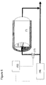
- the storage container 1 is heated by a heating element 2 representing a heating source placed inside the container 1.
- a heating element 2 representing a heating source placed inside the container 1.
- fins 3 representing heat-conducting elements attached to the heating element 2.
- the heating element is powered by electric current.
- the fins 3 are arranged in planes defined by the longitudinal direction of the container 1 (i.e. along its cylinder axis) and the container's radial direction. They are suitably made of aluminium or other light materials with high heat conductivity and resistance to the environment in the container 1.
- the ammonia storage material is made in the shape of blocks 9 to fill out the void in the container 1 (or, in other embodiments, may be put into the unit as powder).
- the storage material 9 is shown both separately and inside the container 1 - both places indicated by item 9.
- ammonia When ammonia is released from the solid by thermal desorption, it passes through a tube with an on/off valve 4 to a buffer volume 5.
- a pressure sensor 10 measures the ammonia desorption pressure and a dosing valve 6 doses ammonia into an exhaust line 7 according to the demand given by a controller 12.
- the controller 12 for example, communicates with an engine control unit (ECU; not shown here).
- An NOx sensor 15 is provided in the exhaust line 7 that delivers an NOx signal to the controller 12 which, in turns, calculates the ammonia demand to remove the NOx.
- the controller 12 gets a predicted ammonia-demand signal from the ECU.
- the storage container 1 is insulated by a thermal insulation 8; it also has means for measuring the temperature 11 on the outside of the container 1 but underneath the insulation material 8.
- the controller 12 uses the signal from the temperature measurement 11 to estimate/predict the heat loss through the insulation material. Since most of the temperature gradient appears at the insulation material 8, this temperature measurement approximately corresponds to the higher temperature level to be used in the heat loss estimation made by the controller 12.
- the lower temperature level to be used in the heat loss estimation is, in some embodiments, measured by a second sensor, e.g. at the outer surface of the insulation material 8; in other embodiments a constant average outside temperature is simply assumed.
- the heating element itself is constructed with a built-in thermocouple. This may serve both as a security for avoiding overheating of the heating element and the temperature measurement may also be used as a parameter in the prediction of the temperature gradient.
- This heat loss estimation controls the heating input to the heating element 2, in a feed-forward manner.
- the amount of heat needed to compensate the desorption energy in a two-step procedure, in which first the ammonia demand is calculated, and then the heat required to compensate the desorption energy for this demand is calculated.
- the (measured or predicted) NOx is directly mapped to a number indicating the heat required to compensate the desorption energy for the amount of ammonia to be released to remove the measured or predicted NOx, by a suitable mapping table or formula. This heat may then directly be combined with the estimated heat loss to obtain the amount of heat to be produced by the heating element 2.
- the controller controls the electric energy delivered to the heat element 2 such that the required amount of heat is produced by the heat element 2. For example, it is able to vary the voltage and/or current in a continuous manner, according to the need. In other embodiments, the supply to the heating element 2 is permanently switched on and off, with a duty cycle corresponding to the amount of heat required.
- the NOx-containing exhaust gas is produced by a combustion engine or burner, eg. an internal combustion engine 13, and emitted into the exhaust line 7.
- the NOx sensor 15 is arranged downstream in the exhaust line 7. Further downstream the ammonia, dosed by the dosing valve 6, is discharged into the exhaust line 7. Still further downstream is an exhaust chamber housing an NOx reduction catalyst 14 capable of removing NOx by reaction with ammonia.
- the ammonia is dosed such by the dosing valve 6 that the dosed amount is just sufficient able to remove the current (measured or predicted) NOx in the exhaust gas, without any significant amount of ammonia being emitted to the atmosphere.
- Figure 2 shows different alternatives (a to c) of applying the concept of internal embedded heating of the storage material 9 with large material length scales (the latter will be explained in connection with Fig. 6 ):
- Figure 3 shows another embodiment in which the internal embedded heating is arranged in a cylindrical container 1 with a heating element on the cylinder axis 2 and heating fins 3 of a disc-like shape and arranged perpendicularly to the container's cylinder axis.
- blocks 9 are, for example, of cylindrical shape with a central hole in order to fit on the heating rod 2.
- the heating rod 2 has separate internal heating zones, or "sections", and each heating disc (or fin) 3 may dissipate energy to one section (or two neighboured sections) while another zone is not heated.
- each heating disc (or fin) 3 may dissipate energy to one section (or two neighboured sections) while another zone is not heated.
- Figure 4 shows a particular configuration in which heating rod 2 is provided with porous metal sheets acting as heating fins 3, attached to the heating rod 2 along the longitudinal direction, similar to Figures 1 and 2 .
- the ammonia released from the storage blocks 9 can then flow in the container's longitudinal direction through the porous metal sheets 3 which may provide faster ammonia release.
- the heating rod 2 may dissipate the heat through conduction in the porous metal sheet 3.
- the porosity of the e.g. sintered metal sheet is below 90% as otherwise the heat conductivity could be too low.
- perpendicularly arranged fins, as in Fig. 3 are made of porous metal
- Fig. 5 shows an embodiment similar to Fig. 1 , but with a heat exchanger as the heat element 2.
- a hot fluid acting as a heating medium is flowed through a central bore in the heating element 2.
- the heating medium conveys some of its heat to the surrounding heat element 2, due to heat conduction.
- the heating medium is, for example, heated by waste heat produced by an engine (or a burner or chemical reaction chamber etc.) 16.
- a continuously regulable valve 17 arranged in the heating-medium circuit is controlled by the controller 12 to adjust (i.e. vary) the flow of the heating medium in such a manner that the heating medium conveys the amount of heat required to the heat element 2.
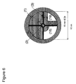
- Fig. 6 illustrates what is meant by the maximum heat diffusion path length, based on cross-sectional view of the storage container of Fig. 1 .
- the container 1 is a cylinder having a circular cross section with an inner diameter of 10cm (100mm).
- the storage material placed in the range of distances in which the distance to the central heat element 2, i.e. is greater than 15 mm is shown as a white area at 18 (at the lower left quarter in Fig . 6 ).
- the storage material placed in the range of distances in which the distance to nearest hot surface (central heating element 2 or heat conducting element 3) is greater than 15 mm is shown as a white area at 19 19 (at the lower right quarter in Fig. 6 ).
- the heat diffusion path length is the "heat diffusion path length”.
- the heat diffusion path length is smaller than 15mm.
- the maximum of the heat diffusion path length that appears somewhere in the container 2 is called the “maximum heat diffusion path length" herein.
- the "maximum heat diffusion path length" is greater than 15 mm because there is some storage material (namely the storage material at 19) for which the heat diffusion path length is greater than 15 mm.
- Heat diffusion path lengths translate into heat diffusion times.
- the smaller is the maximum heat diffusion path length the shorter is the delay between the supply of heat and the corresponding release of ammonia. Consequently, in a purely feedback-controlled system, one would tend to adopt a design with a small maximum heat diffusion path length, significantly smaller than 15 mm. Since a fast response of the ammonia release is not a disadvantage in a feed-forward controlled system, either, in some of the embodiments of the present invention a maximum heat diffusion path length below 15 mm is chosen.
- the maximum heat diffusion path length is greater than 15 mm, e.g. up to 100mm or beyond.
- Such a system has a less complicated internal structure of fins and is thus be more interesting from an industrial applicability point-of-view.
- Figure 7 shows delays due to heat conduction in two different experiments that are only based on feedback control of the heat supply.
- ammonia dosing according to three consecutive driving cycles with intermediate parking was carried out.
- Two different types of federally approved driving cycles are used: FTP-75 and US-06 (the latter includes more high-speed driving).
- the driving cycles simulate certain driving conditions. They are characterized by a definition of the vehicle speed as a function of time. When this speed curve is differentiated, one can get a dynamic curve showing where a car would produce much NOx (during acceleration) and thus need larger dosing rates of ammonia.
- the testing cycle consist of one FTP-75, a "parking period" of 1 hour, a US06 driving cycle, 2 hours of "parking” and finally again one FTP-75 cycle.
- One setup consists of:
- EXTERNAL HEATING this shows the pressure a function of time during the entire experiment when the experiment is carried out using an EXTERNAL heating element (as one traditionally would do). It is easy to see that it takes more than 10 minutes to reach a suitable buffer pressure and when it is finally reached, the thermal inertia of the system causes a dramatic over-shoot of up to 4 bars (also during parking).
- the next driving cycle starts with a high pressure because the over-shoot from the first cycle is not "reduced”. But during the next cycle, the feedback control is unable to avoid a large under-shoot in pressure (well below the set-point) and a too low pressure makes it impossible to dose the right amount of ammonia.
- the last cycle is seen to have large oscillations in pressure and also the first period of approximate 10 minutes where the pressure is far too low.
- Figure 8 shows the accumulated ammonia dosed during the second driving cycle of figure 5 (from 94-104 minutes).
- This is a US-06 driving cycle and the assumed ammonia demand amounts to an integral need of approximately 7 liters of ammonia gas to be dosed.
- the figure shows the difference in dosing ability using the INTERNAL vs. EXTERNAL heating. Any increase in the vertical distance between the two curves means that the system using EXTERNAL heating cannot follow the demand of ammonia defined by the assumed driving cycle. Especially in the last 4 minutes of the cycle, almost no increase in the accumulated ammonia dosing curve is seen.
- the EXTERNAL heating delivers less than five out of the seven liters needed.
- the INTERNAL heating follows the driving cycle.
- the EXTERNAL heating system only manages to dose approximately four out of six liters of needed ammonia gas.
- the pressure curve for EXTERNAL heating is very low in the first 5-10 minutes.
- INTERNAL heating is able to deliver the desired amount of ammonia.
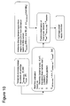
- Figure 10 illustrates the feed-forward control strategy that further enables the control of a system for large capacity, including (but not limited to) systems with long heat diffusion path length scales of the storage material, e.g. above 15mm.
- the time-delay for heat transfer is substantial, even with internal embedded heat-ing.
- An aim of a control strategy is to avoid reaching a state of "subcooling" created by a large release rates of ammonia, which cools the material since the desorption is endothermic. This cooling effect is created locally - where ammonia is desorbed - but the new supply of heat must reach that desorption "front" in the material and this is potentially far away from the heating source.
- a storage unit needs heat for two things: a) to maintain the temperature of the system without ammonia being desorbed (compensating for heat loss) and b) to supply the necessary amount of heat for ammonia desorption to avoid cooling of the material.
- the controller may also comprise an algorithm that estimates the heat-loss parameters during e.g. a period of 10 minutes of system operation.
- the coupling of the knowledge of amount of heat input and the amount of released ammonia over a specific period of time (e.g. 10 minutes) will enable the controller to estimate the value of A ⁇ h (if the temperature gradient is known). It will not be able to estimate the value of two parameters, A and h, independently but the description of the heat loss as a function of temperature gradient will generally be sufficient if the value of A ⁇ h is known.
- Figure 11 shows an overlaid feedback control to provide an additional safety feature of the control system.
- the pressure scale shown indicates different pressure levels in the pressure control strategy.
- the basis pressure is the atmospheric pressure of the surroundings.
- P Exhaust line 1.2 bar.
- Dosing of ammonia is not possible unless the dosing valve gets a certain supply pressure from the buffer of P Minimum (as an example say 1.5 bars).
- the normal set-point is P NH3, setpoint (e.g. 1.8 bars).
- the control strategy presented in figure 8 might only be active in the pressure range between P NH3, setpoint and P Heat-off (e.g. 2.2 bars). Above a certain pressure (P Heat-off ), the heat is turned off at any rate as a safety feature.
- P Heat-off is higher than the set-point in a conventional feedback control would be, since it is a safety feature, but the "normal" control is performed by the feed-forward part.
- an optional pressure relief valve will open to avoid any pressure above a mechanical design level.
- FIG. 12 illustrates other embodiments in which the released ammonia is not used to reduce NOx, but serves as a fuel for fuel cells.
- ammonia stored in a container (1) in storage material (9) is released by a heater (2) based on a feed-forward control of the heat supplied, as explained in illustrated in thee previous figures.
- the released ammonia is supplied to a catalytic cracker (20); the produced hydrogen is fed to a fuel cell (21 a) capable of converting hydrogen to electricity.
- the released ammonia is directly supplied to a fuel cell (21 b) capable of directly converting ammonia to electricity.
- the feed-forward control strategy of figure 10 constitutes a control strategy that can handle the long time-delays of operating combined with a safe ammonia storage system using endothermic ammonia desorption from storage units with large material length scales above 15mm.
- the strategy of figures 10 and 11 is well-suited for the concept of internal heating as the heat-compensating term is easier to compute.
- One reason is that while the temperature of the internal heating element will typically fluctuate quite substantially, the temperature of the container wall will almost be constant over longer periods of time - and therefore the temperature gradient to the surroundings does not change rapidly. If an external heating was applied, the temperature gradient to the surroundings would change very dynamically because the temperature of the container wall would increase and decrease with every initiation and ending of a heating period.
Priority Applications (11)
| Application Number | Priority Date | Filing Date | Title |
|---|---|---|---|
| EP07006706A EP1977817B1 (de) | 2007-03-30 | 2007-03-30 | System zur Lagerung von Ammoniak in und zu seiner Abgabe aus einem Lagerungsmaterial und Verfahren zur Lagerung und Abgabe von Ammoniak |
| DE602007010728T DE602007010728D1 (de) | 2007-03-30 | 2007-03-30 | System zur Lagerung von Ammoniak in und zu seiner Abgabe aus einem Lagerungsmaterial und Verfahren zur Lagerung und Abgabe von Ammoniak |
| AT07006706T ATE489158T1 (de) | 2007-03-30 | 2007-03-30 | System zur lagerung von ammoniak in und zu seiner abgabe aus einem lagerungsmaterial und verfahren zur lagerung und abgabe von ammoniak |
| ES07006706T ES2355274T3 (es) | 2007-03-30 | 2007-03-30 | Sistema para almacenar amoniaco y liberar amoniaco de un material de almacenamiento y procedimiento para almacenar y liberar amoniaco. |
| CN2008800103778A CN101678275B (zh) | 2007-03-30 | 2008-03-26 | 用于将氨存储在存储材料中并从存储材料释放氨的系统以及用于存储和释放氨的方法 |
| PCT/EP2008/002386 WO2008119492A1 (en) | 2007-03-30 | 2008-03-26 | A system for storing ammonia in and releasing ammonia from a storage material and method for storing and releasing ammonia |
| EP08734784A EP2134451A1 (de) | 2007-03-30 | 2008-03-26 | System zur lagerung von ammoniak in und der abgabe aus einem lagerungsmaterial und verfahren zur lagerung und abgabe von ammoniak |
| JP2010500135A JP5154638B2 (ja) | 2007-03-30 | 2008-03-26 | 貯蔵材料にアンモニアを貯蔵し、そこからアンモニアを放出するためのシステムならびにアンモニアを貯蔵および放出するための方法 |
| US12/557,895 US20100021780A1 (en) | 2007-03-30 | 2009-09-11 | System for Storing Ammonia In and Releasing Ammonia from a Stroage Material and Method for Storing and Releasing Ammonia |
| US13/479,402 US9010091B2 (en) | 2007-03-30 | 2012-05-24 | System for storing ammonia in and releasing ammonia from a storage material and method for storing and releasing ammonia |
| US14/662,910 US20150252949A1 (en) | 2007-03-30 | 2015-03-19 | System for storing ammonia in and releasing ammonia from a storage material and method for storing and releasing ammonia |
Applications Claiming Priority (1)
| Application Number | Priority Date | Filing Date | Title |
|---|---|---|---|
| EP07006706A EP1977817B1 (de) | 2007-03-30 | 2007-03-30 | System zur Lagerung von Ammoniak in und zu seiner Abgabe aus einem Lagerungsmaterial und Verfahren zur Lagerung und Abgabe von Ammoniak |
Publications (2)
| Publication Number | Publication Date |
|---|---|
| EP1977817A1 true EP1977817A1 (de) | 2008-10-08 |
| EP1977817B1 EP1977817B1 (de) | 2010-11-24 |
Family
ID=38434816
Family Applications (2)
| Application Number | Title | Priority Date | Filing Date |
|---|---|---|---|
| EP07006706A Not-in-force EP1977817B1 (de) | 2007-03-30 | 2007-03-30 | System zur Lagerung von Ammoniak in und zu seiner Abgabe aus einem Lagerungsmaterial und Verfahren zur Lagerung und Abgabe von Ammoniak |
| EP08734784A Withdrawn EP2134451A1 (de) | 2007-03-30 | 2008-03-26 | System zur lagerung von ammoniak in und der abgabe aus einem lagerungsmaterial und verfahren zur lagerung und abgabe von ammoniak |
Family Applications After (1)
| Application Number | Title | Priority Date | Filing Date |
|---|---|---|---|
| EP08734784A Withdrawn EP2134451A1 (de) | 2007-03-30 | 2008-03-26 | System zur lagerung von ammoniak in und der abgabe aus einem lagerungsmaterial und verfahren zur lagerung und abgabe von ammoniak |
Country Status (8)
| Country | Link |
|---|---|
| US (3) | US20100021780A1 (de) |
| EP (2) | EP1977817B1 (de) |
| JP (1) | JP5154638B2 (de) |
| CN (1) | CN101678275B (de) |
| AT (1) | ATE489158T1 (de) |
| DE (1) | DE602007010728D1 (de) |
| ES (1) | ES2355274T3 (de) |
| WO (1) | WO2008119492A1 (de) |
Cited By (35)
| Publication number | Priority date | Publication date | Assignee | Title |
|---|---|---|---|---|
| EP2103788A3 (de) * | 2008-03-17 | 2009-12-30 | Robert Bosch GmbH | Vorrichtung und Verfahren zur thermodynamischen und druckaufbauenden Freisetzung von Ammoniak |
| FR2950651A1 (fr) * | 2009-09-29 | 2011-04-01 | Peugeot Citroen Automobiles Sa | Dispositif d'injection dans une ligne d'echappement d'un agent reducteur gazeux |
| EP2305979A1 (de) * | 2009-10-01 | 2011-04-06 | Amminex A/S | Verbundene wärmeleitende Strukturen in festen Ammoniakspeichersystemen |
| WO2011038916A1 (en) * | 2009-09-30 | 2011-04-07 | Amminex A/S | Connected heat conducting structures in solid ammonia storage systems |
| DE102009060285A1 (de) | 2009-12-23 | 2011-06-30 | Volkswagen AG, 38440 | Verfahren zur Bestimmung eines NH3-Beladungsstandes eines Speichers eines SCR-Katalysatorsystems, SCR-Katalysatorsystem und Fahrzeug |
| WO2011113454A1 (en) * | 2010-03-16 | 2011-09-22 | Amminex A/S | Method and device for controlled dosing of a gas with fluctuating supply pressure |
| WO2011121196A1 (fr) | 2010-03-29 | 2011-10-06 | Peugeot Citroën Automobiles SA | Dispositif d'injection dans une ligne d'echappement d'un agent reducteur gazeux |
| EP2412946A1 (de) * | 2010-07-28 | 2012-02-01 | Aaqius & Aaqius S.A. | Verfahren zur Reduzierung der Menge an Stickoxiden (NOx) in Abgasen von Kraftfahrzeugen |
| EP2428490A1 (de) * | 2010-09-10 | 2012-03-14 | Aaqius & Aaqius S.A. | Verfahren zur Reduzierung der Menge an Stickoxiden (NOx) in Abgasen von Kraftfahrzeugen |
| WO2012034706A1 (en) * | 2010-09-17 | 2012-03-22 | Amminex A/S | Method of determining the filling level of a solid ammonia storage medium in an ammonia storage container |
| FR2973834A1 (fr) * | 2011-04-05 | 2012-10-12 | Peugeot Citroen Automobiles Sa | Procede de controle d'un systeme d'injection avec chauffage par electrovanne de dosage, vehicule correspondant |
| FR2974388A1 (fr) * | 2011-04-20 | 2012-10-26 | Peugeot Citroen Automobiles Sa | Procede de validation de changement de cartouche de reducteur dans un systeme scr, ligne d'echappement et vehicule |
| FR2974389A1 (fr) * | 2011-04-20 | 2012-10-26 | Peugeot Citroen Automobiles Sa | Procede de detection d'un changement de cartouche de reducteur dans un systeme scr, ligne d'echappement et vehicule |
| FR2974390A1 (fr) * | 2011-04-20 | 2012-10-26 | Peugeot Citroen Automobiles Sa | Procede de detection de changement de cartouche de reducteur dans un systeme scr, ligne d'echappement et vehicule |
| WO2012143633A1 (fr) * | 2011-04-20 | 2012-10-26 | Peugeot Citroen Automobiles Sa | Procede de validation et de detection de changement de cartouche de reducteur dans un systeme scr, ligne d'echappement et vehicule |
| EP2522823A1 (de) | 2011-05-13 | 2012-11-14 | Aaqius & Aaqius S.A. | Vorrichtung zur Messung der Menge eines in einem Behälter enthaltenen Reduktionsmittels, vorzugsweise NH3 |
| EP2538051A1 (de) | 2011-06-24 | 2012-12-26 | Aaqius & Aaqius S.A. | Verfahren zur Feststellung der Menge eines Reduktionsmittels in einem Behälter |
| WO2013068669A1 (fr) * | 2011-11-10 | 2013-05-16 | Peugeot Citroen Automobiles Sa | Cartouche de stockage d'un reducteur gazeux pour la reduction catalytique selective des oxydes d'azote |
| US8473226B2 (en) | 2010-09-17 | 2013-06-25 | Amminex A/S | Method of determining the filling level of a solid ammonia storage medium in an ammonia storage container |
| DE102011122413A1 (de) | 2011-12-24 | 2013-06-27 | Volkswagen Aktiengesellschaft | Verfahren zum Betreiben eines Ammoniakspeichersystems eines SCR-Katalysators sowie ein entsprechendes Ammoniakspeichersystem |
| FR2991712A1 (fr) * | 2012-06-06 | 2013-12-13 | Faurecia Sys Echappement | Dispositif de generation d'ammoniac |
| FR2991711A1 (fr) * | 2012-06-06 | 2013-12-13 | Faurecia Sys Echappement | Dispositif de generation d'ammoniac |
| FR2992349A1 (fr) * | 2012-06-22 | 2013-12-27 | Peugeot Citroen Automobiles Sa | Procede de commande d'un systeme d'alimentation en agent reducteur pour le traitement d'oxydes d'azote dans une ligne d'echappement de vehicule automobile |
| WO2014001733A1 (fr) * | 2012-06-29 | 2014-01-03 | Inergy Automotive Systems Research (Société Anonyme) | Procédé de diagnostic d'un système de stockage d'un gaz stocké par sorption sur un composé |
| EP2696048A1 (de) * | 2012-08-09 | 2014-02-12 | Aaqius & Aaqius S.A. | Messung der Restkapazität eines Speicher- und Dosiersystems von gasförmigem Ammoniak |
| EP2695859A1 (de) * | 2012-08-09 | 2014-02-12 | Aaqius & Aaqius S.A. | Struktur zur Lagerung von Ammoniak und entsprechende Systeme und Verfahren |
| WO2014023841A1 (fr) * | 2012-08-09 | 2014-02-13 | Aaqius & Aaqius Sa | Unite de stockage d'ammoniac et structure et systeme associes |
| WO2014096426A1 (en) * | 2012-12-21 | 2014-06-26 | Inergy Automotive Systems Research (Société Anonyme) | Method and system for generating power on board a vehicle |
| EP2749746A1 (de) * | 2012-12-31 | 2014-07-02 | Aaqius & Aaqius S.A. | Lagereinheit für Ammoniak, entsprechende Struktur und entsprechendes System |
| CN103912348A (zh) * | 2014-04-08 | 2014-07-09 | 刘观柏 | 一种电加热的碳酸氢铵干法制氨及计量喷射系统 |
| WO2014167128A1 (fr) * | 2013-04-12 | 2014-10-16 | Aaqius & Aaqius Sa | Structure de stockage d'ammoniac et systemes associes |
| ITBO20130370A1 (it) * | 2013-07-16 | 2015-01-17 | Magneti Marelli Spa | Serbatoio di raccolta di matrici solide per immagazzinare ammoniaca per un sistema di scarico provvisto di post-trattamento dei gas di scarico in un motore a combustione interna |
| US8951437B2 (en) | 2009-09-30 | 2015-02-10 | Amminex Emissions Technology A/S | Connected heat conducting structures in solid ammonia storage systems |
| EP2944780A1 (de) | 2014-05-12 | 2015-11-18 | Magneti Marelli S.p.A. | Behälter für festes Material zur Speicherung von Ammoniak für ein Abgassystem zur Abgasnachbehandlung in einem Verbrennungsmotor |
| EP2944779A1 (de) | 2014-05-12 | 2015-11-18 | Magneti Marelli S.p.A. | Abgassystem für Abgasnachbehandlung in einem Verbrennungsmotor mit einem Behälter für Speichermaterial zur Speicherung von Ammoniak |
Families Citing this family (58)
| Publication number | Priority date | Publication date | Assignee | Title |
|---|---|---|---|---|
| US9400064B2 (en) * | 2007-05-23 | 2016-07-26 | Amminex A/S | Method and device for ammonia storage and delivery using in-situ re-saturation of a delivery unit |
| DE102007060221B4 (de) | 2007-12-14 | 2021-12-30 | Robert Bosch Gmbh | Verfahren zur Reduktionsmittelbereitstellung in einer Abgasnachbehandlungsanlage |
| EP2175246B1 (de) * | 2008-10-09 | 2017-07-19 | Sensirion AG | Verfahren zur Messung eines Parameters einer Fluidzusammensetzung mithilfe eines Flusssensors |
| EP2204555B1 (de) * | 2009-01-02 | 2011-08-03 | Sensirion AG | Ammoniakspeichersystem |
| DE102009030405A1 (de) * | 2009-06-25 | 2010-12-30 | Bayerische Motoren Werke Aktiengesellschaft | Einrichtung zum Speichern von Ammoniak und Verfahren zum Einlagern von Ammoniak in einer Speichereinrichtung |
| AU2010345799B2 (en) * | 2010-02-12 | 2015-01-15 | Stamicarbon B.V. | Removal of ammonia in urea finishing |
| EP2361883A1 (de) * | 2010-02-25 | 2011-08-31 | Amminex A/S | Verfahren zur Bestimmung des Sättigungsgrads von Materialien zur Aufbewahrung von festem Ammoniak in Behältern |
| EP2536480B1 (de) * | 2010-03-16 | 2017-05-10 | Amminex Emissions Technology A/S | Verfahren und vorrichtung zur steuerung einer effizienten wärmeübertragung in einem feststoff-ammoniak-speichersystem |
| JP5371851B2 (ja) * | 2010-03-25 | 2013-12-18 | 株式会社日本触媒 | 固体酸化物形燃料電池 |
| BR112012026931A2 (pt) * | 2010-04-21 | 2016-07-12 | Int Engine Intellectual Prop | dispositivo de recarga e método para cartucho de nh3 |
| JP2011236105A (ja) * | 2010-05-13 | 2011-11-24 | Toyota Industries Corp | アンモニア放出装置、アンモニア放出方法及び排気ガス浄化装置 |
| EP2388058A1 (de) * | 2010-05-19 | 2011-11-23 | Amminex A/S | Verfahren und Vorrichtung zur erneuten Sättigung von Ammoniakspeichermaterial in Behältern |
| JP5625627B2 (ja) * | 2010-08-30 | 2014-11-19 | 株式会社豊田中央研究所 | アンモニア吸蔵装置および選択的触媒還元システム |
| FR2965856B1 (fr) | 2010-10-12 | 2017-03-24 | Peugeot Citroen Automobiles Sa | Procede de controle du fonctionnement d'un systeme de post-traitement des gaz d'echappement d'un moteur et vehicule adapte pour la mise en œuvre du procede |
| US20120177553A1 (en) * | 2010-12-07 | 2012-07-12 | Lindemann Scott H | Injector And Method For Reducing Nox Emissions From Boilers, IC Engines and Combustion Processes |
| JP5609766B2 (ja) * | 2011-05-13 | 2014-10-22 | 株式会社デンソー | 燃料供給システム |
| DE102011103109A1 (de) * | 2011-05-25 | 2012-11-29 | Benteler Automobiltechnik Gmbh | Abgassystem mit Wärmespeicher |
| EP2715208B1 (de) * | 2011-05-31 | 2016-07-20 | Wärtsilä Oil & Gas Systems AS | Verfahren und system zur verarbeitung von ladungsdämpfen aus rohöl- und erdölprodukttanks zur erzeugung von elektrizität |
| WO2012170769A1 (en) * | 2011-06-09 | 2012-12-13 | International Engine Intellectual Property Company, Llc | Method for filling an ammonia cartridge |
| US8940260B2 (en) * | 2011-06-10 | 2015-01-27 | International Engine Intellectual Property Company, Llc. | Supplemental ammonia storage and delivery system |
| KR20130024079A (ko) * | 2011-08-30 | 2013-03-08 | 현대자동차주식회사 | 고체 scr 시스템 및 이를 이용한 고체상의 환원제 가열 방법 |
| JP5630411B2 (ja) * | 2011-09-26 | 2014-11-26 | 株式会社豊田中央研究所 | 熱回収式加熱装置 |
| EP2574599A1 (de) * | 2011-09-30 | 2013-04-03 | Inergy Automotive Systems Research (Société Anonyme) | Behälter für die Speicherung von Ammoniak durch Sorption |
| WO2013109258A1 (en) * | 2012-01-18 | 2013-07-25 | International Engine Intellectual Property Company, Llc | Ammonia gas pressure booster |
| US9222389B2 (en) * | 2012-02-02 | 2015-12-29 | Cummins Inc. | Systems and methods for controlling reductant delivery to an exhaust stream |
| US8820058B2 (en) | 2012-02-02 | 2014-09-02 | Cummins Inc. | System, method, and apparatus for determining solid storage media quality for a NOx reductant |
| WO2013133811A1 (en) * | 2012-03-07 | 2013-09-12 | International Engine Intellectual Property Company, Llc | Outer clam shells with identically molded top and bottom pieces |
| US20130239554A1 (en) * | 2012-03-19 | 2013-09-19 | GM Global Technology Operations LLC | Exhaust gas treatment system having a solid ammonia gas producing material |
| US9562649B2 (en) * | 2012-04-25 | 2017-02-07 | Saudi Arabian Oil Company | Adsorbed natural gas storage facility |
| US20150159532A1 (en) * | 2012-06-11 | 2015-06-11 | International Engine Intellectual Property Company , Llc | Wear plate between canister and electric heating elements |
| CN102720572B (zh) * | 2012-06-29 | 2016-06-29 | 中国第一汽车股份有限公司 | 排气管余热方式的活性物储氨供氨的后处理控制单元 |
| EP2695858B1 (de) | 2012-08-09 | 2015-09-16 | Aaqius & Aaqius S.A. | System zur Lagerung und Abgabe von gasförmigem Ammoniak |
| CN102838132B (zh) * | 2012-09-05 | 2014-12-17 | 河北科技大学 | 一种氯化铵分解生产氨和高浓度氯化钙的方法 |
| FR2995629B1 (fr) * | 2012-09-14 | 2014-10-17 | Faurecia Sys Echappement | Dispositif de stockage d'ammoniac et ligne d'echappement equipee d'un tel dispositif |
| WO2014070245A1 (en) * | 2012-11-02 | 2014-05-08 | International Engine Intellectual Property Company, Llc | Power modulation for ammonia delivery system |
| US10067045B2 (en) * | 2012-11-02 | 2018-09-04 | International Engine Intellectual Property Company, Llc. | Ammonia estimation method |
| US9334778B2 (en) | 2013-03-07 | 2016-05-10 | Cummins Ip, Inc. | Solid ammonia delivery system |
| FR3004436B1 (fr) * | 2013-04-12 | 2016-10-21 | Aaqius & Aaqius Sa | Structure de stockage d'ammoniac et systemes associes |
| FR3004435B1 (fr) * | 2013-04-12 | 2016-10-21 | Aaqius & Aaqius Sa | Structure de stockage d'ammoniac et systemes associes |
| US20160083259A1 (en) * | 2013-04-22 | 2016-03-24 | International Engine Intellectual Property Company, Llc | Reductant storage |
| CN103437866B (zh) * | 2013-07-25 | 2015-07-29 | 吉林大学 | 为车用选择性催化还原系统全工况提供还原剂方法及装置 |
| JP2015071989A (ja) * | 2013-10-04 | 2015-04-16 | 株式会社豊田自動織機 | アンモニア吸蔵放出装置及び排気ガス浄化システム |
| CN103556118B (zh) * | 2013-10-12 | 2016-03-02 | 深圳市华星光电技术有限公司 | 蒸镀装置 |
| US9914645B2 (en) | 2013-11-07 | 2018-03-13 | Regents Of The University Of Minnesota | Process for making ammonia |
| FR3015454B1 (fr) * | 2013-12-20 | 2016-01-01 | Aaqius & Aaqius Sa | Dispositif et procede de rechargement de cartouche d'ammoniac pour reduction des oxydes d'azote par reduction catalytique selective dans un vehicule |
| FR3015455B1 (fr) * | 2013-12-20 | 2017-04-21 | Aaqius & Aaqius Sa | Systeme modulaire de stockage d'ammoniac |
| CN104100337B (zh) * | 2014-07-24 | 2017-02-15 | 吉林省众鑫汽车装备有限公司 | 一种固态还原剂选择性催化还原系统 |
| WO2016194682A1 (ja) * | 2015-06-02 | 2016-12-08 | 株式会社豊田自動織機 | 化学蓄熱装置 |
| US10437410B2 (en) * | 2016-03-31 | 2019-10-08 | Cisco Technology, Inc. | Conversation sub-window |
| FR3063329B1 (fr) * | 2017-02-24 | 2020-10-30 | Aaqius & Aaqius Sa | Dispositif de stockage d'hydrogene |
| FR3071871B1 (fr) * | 2017-09-29 | 2020-02-07 | Continental Automotive France | Procede de reduction catalytique selective avec desorption d'ammoniac a partir d'une cartouche dans une ligne d'echappement |
| EP3498993A1 (de) | 2017-12-15 | 2019-06-19 | Umicore Ag & Co. Kg | Kombination eines zeolithbasierten scr mit einem manganbasierten scr im bypass |
| CN109373184B (zh) * | 2018-10-18 | 2024-03-19 | 浙江英德赛半导体材料股份有限公司 | 一种大功率高纯氨车载加热系统 |
| US10392989B1 (en) | 2018-10-19 | 2019-08-27 | Faurecia Emissions Control Technologies, Usa, Llc | Automotive exhaust aftertreatment system having an ammonia distributor |
| CN111569645B (zh) * | 2020-05-13 | 2021-10-29 | 上海交通大学 | 多级储氨式固态氨除NOx系统 |
| CN111577430A (zh) * | 2020-05-26 | 2020-08-25 | 宁波楷世环保科技有限公司 | 响应时间短的氨气生成计量喷射装置及喷射率控制系统 |
| US11203966B1 (en) | 2020-09-30 | 2021-12-21 | Faurecia Emissions Control Technologies, Usa, Llc | Circular sampling device for an exhaust gas sensor |
| CN112421077B (zh) * | 2020-11-23 | 2022-05-24 | 浙江大学 | 一种基于氨合氯化锶储热的燃料电池低温启动加热及余热回收系统 |
Citations (7)
| Publication number | Priority date | Publication date | Assignee | Title |
|---|---|---|---|---|
| JPH02258017A (ja) * | 1989-03-31 | 1990-10-18 | Babcock Hitachi Kk | 固体還元剤を用いた排ガス脱硝装置 |
| US5809775A (en) * | 1997-04-02 | 1998-09-22 | Clean Diesel Technologies, Inc. | Reducing NOx emissions from an engine by selective catalytic reduction utilizing solid reagents |
| US6266955B1 (en) * | 1999-08-20 | 2001-07-31 | Caterpillar Inc. | Diagnostic system for an emissions control on an engine |
| WO2004042207A1 (de) * | 2002-11-06 | 2004-05-21 | Robert Bosch Gmbh | Verfahren zur nachbehandlung von abgasen und anordnung hierzu |
| DE10323591A1 (de) * | 2003-05-16 | 2004-12-02 | E.G.O. Elektro-Gerätebau GmbH | Verfahren und Vorrichtung zur Erzeugung eines Gases aus einem Sublimationsgut |
| US20050282285A1 (en) * | 2004-06-21 | 2005-12-22 | Eaton Corporation | Strategy for controlling NOx emissions and ammonia slip in an SCR system using a nonselective NOx/NH3 |
| WO2007000170A1 (en) * | 2005-06-29 | 2007-01-04 | Amminex A/S | Method and device for safe and controlled delivery of ammonia from a solid ammonia storage medium |
Family Cites Families (20)
| Publication number | Priority date | Publication date | Assignee | Title |
|---|---|---|---|---|
| DE3422175A1 (de) * | 1984-06-04 | 1985-12-19 | Julius Dr. 8000 München Kern | Verfahren zur beimischung von ammoniak zu saure schadstoffe enthaltenden abgasen oder luft |
| EP0462226B1 (de) | 1989-03-08 | 1995-05-10 | Rocky Research | Vorrichtung und verfahren zur erhaltung von hohen reaktionsleistungen in fest-gas-reaktorsystemen |
| US5441716A (en) | 1989-03-08 | 1995-08-15 | Rocky Research | Method and apparatus for achieving high reaction rates |
| US5161389A (en) | 1990-11-13 | 1992-11-10 | Rocky Research | Appliance for rapid sorption cooling and freezing |
| JP3965703B2 (ja) * | 1994-12-28 | 2007-08-29 | マツダ株式会社 | エンジンの排気ガス浄化装置及び排気ガス浄化方法 |
| US5968464A (en) * | 1997-05-12 | 1999-10-19 | Clean Diesel Technologies, Inc. | Urea pyrolysis chamber and process for reducing lean-burn engine NOx emissions by selective catalytic reduction |
| DE19728343C5 (de) * | 1997-07-03 | 2013-02-21 | Robert Bosch Gmbh | Verfahren und Vorrichtung zur selektiven katalytischen NOx-Reduktion |
| JP2001042950A (ja) * | 1999-08-02 | 2001-02-16 | Denso Corp | 水素ガス圧緩衝装置および水素ガス圧の緩衝方法 |
| US6725651B2 (en) * | 2000-11-16 | 2004-04-27 | Toyota Jidosha Kabushiki Kaisha | Reducing agent for emission control system, reducing-agent supply device, and emission control system using the reducing agent |
| DE10101364A1 (de) * | 2001-01-13 | 2002-07-18 | Fev Motorentech Gmbh | Verfahren zur Umwandlung eines festen stickstoffhaltigen Reduktionsmittels in eine Gasphase für die Reduktion von Stickoxiden in sauerstoffhaltigen Abgasen nach dem Prinzip der selektiven katalytischen Reduktion |
| DE10206028A1 (de) * | 2002-02-14 | 2003-08-28 | Man Nutzfahrzeuge Ag | Verfahren und Vorrichtung zur Erzeugung von Ammoniak |
| WO2005073527A1 (ja) * | 2004-02-02 | 2005-08-11 | Nissan Diesel Motor Co., Ltd. | 内燃機関の排気浄化装置 |
| KR20070057143A (ko) | 2004-08-03 | 2007-06-04 | 아미넥스 에이/에스 | 고체 암모니아 저장 및 수송 물질 |
| RU2395335C2 (ru) | 2005-02-03 | 2010-07-27 | Амминекс А/С | Хранение аммиака при его высоком содержании |
| JP4500698B2 (ja) * | 2005-02-08 | 2010-07-14 | 三井造船株式会社 | 排ガス処理装置 |
| EP1853799A1 (de) * | 2005-02-16 | 2007-11-14 | Imi Vision Limited | Abgasbehandlung |
| WO2007095955A1 (en) * | 2006-02-27 | 2007-08-30 | Amminex A/S | A method of storing and delivering ammonia and the use of electromagnetic radiation for desorption of ammonia from a chemical complex |
| US8015801B2 (en) * | 2006-09-18 | 2011-09-13 | Ford Global Technologies, Llc | Management of a plurality of reductants for selective catalytic reduction |
| DE102006061370A1 (de) * | 2006-12-22 | 2008-06-26 | Amminex A/S | Verfahren und Vorrichtung zur Ammoniakspeicherung und -zufuhr unter Verwendung von in-situ-Wiedersättigung einer Zufuhreinheit |
| WO2008077626A2 (en) * | 2006-12-22 | 2008-07-03 | Amminex A/S | Method and device for sage storage and delivery of ammonia and use of ammonia storage materials |
-
2007
- 2007-03-30 AT AT07006706T patent/ATE489158T1/de not_active IP Right Cessation
- 2007-03-30 EP EP07006706A patent/EP1977817B1/de not_active Not-in-force
- 2007-03-30 ES ES07006706T patent/ES2355274T3/es active Active
- 2007-03-30 DE DE602007010728T patent/DE602007010728D1/de active Active
-
2008
- 2008-03-26 WO PCT/EP2008/002386 patent/WO2008119492A1/en active Application Filing
- 2008-03-26 JP JP2010500135A patent/JP5154638B2/ja not_active Expired - Fee Related
- 2008-03-26 EP EP08734784A patent/EP2134451A1/de not_active Withdrawn
- 2008-03-26 CN CN2008800103778A patent/CN101678275B/zh not_active Expired - Fee Related
-
2009
- 2009-09-11 US US12/557,895 patent/US20100021780A1/en not_active Abandoned
-
2012
- 2012-05-24 US US13/479,402 patent/US9010091B2/en not_active Expired - Fee Related
-
2015
- 2015-03-19 US US14/662,910 patent/US20150252949A1/en not_active Abandoned
Patent Citations (7)
| Publication number | Priority date | Publication date | Assignee | Title |
|---|---|---|---|---|
| JPH02258017A (ja) * | 1989-03-31 | 1990-10-18 | Babcock Hitachi Kk | 固体還元剤を用いた排ガス脱硝装置 |
| US5809775A (en) * | 1997-04-02 | 1998-09-22 | Clean Diesel Technologies, Inc. | Reducing NOx emissions from an engine by selective catalytic reduction utilizing solid reagents |
| US6266955B1 (en) * | 1999-08-20 | 2001-07-31 | Caterpillar Inc. | Diagnostic system for an emissions control on an engine |
| WO2004042207A1 (de) * | 2002-11-06 | 2004-05-21 | Robert Bosch Gmbh | Verfahren zur nachbehandlung von abgasen und anordnung hierzu |
| DE10323591A1 (de) * | 2003-05-16 | 2004-12-02 | E.G.O. Elektro-Gerätebau GmbH | Verfahren und Vorrichtung zur Erzeugung eines Gases aus einem Sublimationsgut |
| US20050282285A1 (en) * | 2004-06-21 | 2005-12-22 | Eaton Corporation | Strategy for controlling NOx emissions and ammonia slip in an SCR system using a nonselective NOx/NH3 |
| WO2007000170A1 (en) * | 2005-06-29 | 2007-01-04 | Amminex A/S | Method and device for safe and controlled delivery of ammonia from a solid ammonia storage medium |
Cited By (62)
| Publication number | Priority date | Publication date | Assignee | Title |
|---|---|---|---|---|
| EP2103788A3 (de) * | 2008-03-17 | 2009-12-30 | Robert Bosch GmbH | Vorrichtung und Verfahren zur thermodynamischen und druckaufbauenden Freisetzung von Ammoniak |
| FR2950651A1 (fr) * | 2009-09-29 | 2011-04-01 | Peugeot Citroen Automobiles Sa | Dispositif d'injection dans une ligne d'echappement d'un agent reducteur gazeux |
| WO2011039438A1 (fr) * | 2009-09-29 | 2011-04-07 | Peugeot Citroën Automobiles SA | Dispositif d'injection dans une ligne d'echappement d'un agent reducteur gazeux |
| CN102575549A (zh) * | 2009-09-30 | 2012-07-11 | 氨合物公司 | 在固体氨储存体系中相连的热传导结构 |
| WO2011038916A1 (en) * | 2009-09-30 | 2011-04-07 | Amminex A/S | Connected heat conducting structures in solid ammonia storage systems |
| CN104196601A (zh) * | 2009-09-30 | 2014-12-10 | 氨合物排放股份公司 | 在固体氨储存体系中相连的热传导结构 |
| US8951437B2 (en) | 2009-09-30 | 2015-02-10 | Amminex Emissions Technology A/S | Connected heat conducting structures in solid ammonia storage systems |
| EP2305979A1 (de) * | 2009-10-01 | 2011-04-06 | Amminex A/S | Verbundene wärmeleitende Strukturen in festen Ammoniakspeichersystemen |
| US9079779B2 (en) | 2009-10-01 | 2015-07-14 | Amminex Emissions Technology A/S | Connected heat conducting structures in solid ammonia storage systems |
| DE102009060285A1 (de) | 2009-12-23 | 2011-06-30 | Volkswagen AG, 38440 | Verfahren zur Bestimmung eines NH3-Beladungsstandes eines Speichers eines SCR-Katalysatorsystems, SCR-Katalysatorsystem und Fahrzeug |
| WO2011113454A1 (en) * | 2010-03-16 | 2011-09-22 | Amminex A/S | Method and device for controlled dosing of a gas with fluctuating supply pressure |
| US8869514B2 (en) | 2010-03-16 | 2014-10-28 | Amminex Emissions Technology A/S | Method and device for controlled dosing of a gas with fluctuating supply pressure |
| WO2011121196A1 (fr) | 2010-03-29 | 2011-10-06 | Peugeot Citroën Automobiles SA | Dispositif d'injection dans une ligne d'echappement d'un agent reducteur gazeux |
| WO2012014037A1 (fr) * | 2010-07-28 | 2012-02-02 | Aaqius & Aaqius S.A. | Procede destine a reduire la quantite de nox dans les gaz d'echappement d'un vehicule moteur |
| CN103069120B (zh) * | 2010-07-28 | 2015-11-25 | 阿奎斯&阿奎斯股份有限公司 | 用于减少机动车的排放气体中的NOx量的方法 |
| EP2412946A1 (de) * | 2010-07-28 | 2012-02-01 | Aaqius & Aaqius S.A. | Verfahren zur Reduzierung der Menge an Stickoxiden (NOx) in Abgasen von Kraftfahrzeugen |
| CN103069120A (zh) * | 2010-07-28 | 2013-04-24 | 阿奎斯&阿奎斯股份有限公司 | 用于减少机动车的排放气体中的NOx量的方法 |
| EP2428490A1 (de) * | 2010-09-10 | 2012-03-14 | Aaqius & Aaqius S.A. | Verfahren zur Reduzierung der Menge an Stickoxiden (NOx) in Abgasen von Kraftfahrzeugen |
| WO2012034706A1 (en) * | 2010-09-17 | 2012-03-22 | Amminex A/S | Method of determining the filling level of a solid ammonia storage medium in an ammonia storage container |
| US8473226B2 (en) | 2010-09-17 | 2013-06-25 | Amminex A/S | Method of determining the filling level of a solid ammonia storage medium in an ammonia storage container |
| FR2973834A1 (fr) * | 2011-04-05 | 2012-10-12 | Peugeot Citroen Automobiles Sa | Procede de controle d'un systeme d'injection avec chauffage par electrovanne de dosage, vehicule correspondant |
| FR2974389A1 (fr) * | 2011-04-20 | 2012-10-26 | Peugeot Citroen Automobiles Sa | Procede de detection d'un changement de cartouche de reducteur dans un systeme scr, ligne d'echappement et vehicule |
| WO2012172202A1 (fr) | 2011-04-20 | 2012-12-20 | Peugeot Citroen Automobiles Sa | Procede de detection d'un changement de cartouche de reducteur dans un systeme scr, ligne d'echappement et vehicule |
| FR2974388A1 (fr) * | 2011-04-20 | 2012-10-26 | Peugeot Citroen Automobiles Sa | Procede de validation de changement de cartouche de reducteur dans un systeme scr, ligne d'echappement et vehicule |
| FR2974390A1 (fr) * | 2011-04-20 | 2012-10-26 | Peugeot Citroen Automobiles Sa | Procede de detection de changement de cartouche de reducteur dans un systeme scr, ligne d'echappement et vehicule |
| WO2012143633A1 (fr) * | 2011-04-20 | 2012-10-26 | Peugeot Citroen Automobiles Sa | Procede de validation et de detection de changement de cartouche de reducteur dans un systeme scr, ligne d'echappement et vehicule |
| EP2522823A1 (de) | 2011-05-13 | 2012-11-14 | Aaqius & Aaqius S.A. | Vorrichtung zur Messung der Menge eines in einem Behälter enthaltenen Reduktionsmittels, vorzugsweise NH3 |
| CN103597180A (zh) * | 2011-05-13 | 2014-02-19 | 阿奎斯&阿奎斯股份有限公司 | 用于测量包含在容器中的优选为nh3的还原剂量的设备 |
| US9243945B2 (en) | 2011-05-13 | 2016-01-26 | Aaqius & Aaqius Sa | Device for measuring a quantity of a reducing agent, preferably NH3, contained in a vessel |
| WO2012156371A1 (fr) | 2011-05-13 | 2012-11-22 | Aaqius & Aaqius Sa | Dispositif de mesure d'une quantité d'un agent réducteur, de préférence de nh3, contenu dans un réservoir |
| EP2538051A1 (de) | 2011-06-24 | 2012-12-26 | Aaqius & Aaqius S.A. | Verfahren zur Feststellung der Menge eines Reduktionsmittels in einem Behälter |
| WO2012175661A1 (fr) | 2011-06-24 | 2012-12-27 | Aaqius & Aaqius Sa | Procede pour determiner la quantite d'un agent reducteur dans un reservoir |
| WO2013068669A1 (fr) * | 2011-11-10 | 2013-05-16 | Peugeot Citroen Automobiles Sa | Cartouche de stockage d'un reducteur gazeux pour la reduction catalytique selective des oxydes d'azote |
| FR2982638A1 (fr) * | 2011-11-10 | 2013-05-17 | Peugeot Citroen Automobiles Sa | Cartouche de stockage d'un reducteur gazeux pour la reduction catalytique selective des oxydes d'azote. |
| DE102011122413B4 (de) | 2011-12-24 | 2023-08-17 | Volkswagen Aktiengesellschaft | Verfahren zum Betreiben eines Ammoniakspeichersystems eines SCR-Katalysators sowie ein entsprechendes Ammoniakspeichersystem |
| DE102011122413A1 (de) | 2011-12-24 | 2013-06-27 | Volkswagen Aktiengesellschaft | Verfahren zum Betreiben eines Ammoniakspeichersystems eines SCR-Katalysators sowie ein entsprechendes Ammoniakspeichersystem |
| FR2991712A1 (fr) * | 2012-06-06 | 2013-12-13 | Faurecia Sys Echappement | Dispositif de generation d'ammoniac |
| US9567884B2 (en) | 2012-06-06 | 2017-02-14 | Faurecia Systemes D'echappement | Device for generating ammonia |
| US9624802B2 (en) | 2012-06-06 | 2017-04-18 | Faurecia Systemes D'echappement | Device for generating ammonia |
| FR2991711A1 (fr) * | 2012-06-06 | 2013-12-13 | Faurecia Sys Echappement | Dispositif de generation d'ammoniac |
| FR2992349A1 (fr) * | 2012-06-22 | 2013-12-27 | Peugeot Citroen Automobiles Sa | Procede de commande d'un systeme d'alimentation en agent reducteur pour le traitement d'oxydes d'azote dans une ligne d'echappement de vehicule automobile |
| FR2992726A1 (fr) * | 2012-06-29 | 2014-01-03 | Inergy Automotive Systems Res | Procede de diagnostic d'un systeme de stockage d'un gaz stocke par sorption sur un compose. |
| WO2014001733A1 (fr) * | 2012-06-29 | 2014-01-03 | Inergy Automotive Systems Research (Société Anonyme) | Procédé de diagnostic d'un système de stockage d'un gaz stocké par sorption sur un composé |
| CN104641082A (zh) * | 2012-08-09 | 2015-05-20 | 阿奎斯&阿奎斯股份有限公司 | 计量用于存储和传送气态氨的系统的自治 |
| US10315161B2 (en) | 2012-08-09 | 2019-06-11 | Aaqius & Aaqius Sa | Gauging the autonomy of a system for storing and delivering gaseous ammonia |
| US10502367B2 (en) | 2012-08-09 | 2019-12-10 | Aaqius & Aaqius Sa | Gas storage unit and associated structure and system |
| EP2696048A1 (de) * | 2012-08-09 | 2014-02-12 | Aaqius & Aaqius S.A. | Messung der Restkapazität eines Speicher- und Dosiersystems von gasförmigem Ammoniak |
| US9878917B2 (en) | 2012-08-09 | 2018-01-30 | Aaqius & Aaqius Sa | Ammonia storage structure and associated systems and method |
| CN104583551A (zh) * | 2012-08-09 | 2015-04-29 | 阿奎斯&阿奎斯股份有限公司 | 氨气存储单元及相关的结构和系统 |
| WO2014023840A1 (fr) * | 2012-08-09 | 2014-02-13 | Aaqius & Aaqius Sa | Structure de stockage d'ammoniac et systemes et procede associes |
| EP2695859A1 (de) * | 2012-08-09 | 2014-02-12 | Aaqius & Aaqius S.A. | Struktur zur Lagerung von Ammoniak und entsprechende Systeme und Verfahren |
| WO2014023841A1 (fr) * | 2012-08-09 | 2014-02-13 | Aaqius & Aaqius Sa | Unite de stockage d'ammoniac et structure et systeme associes |
| WO2014023836A1 (fr) * | 2012-08-09 | 2014-02-13 | Aaqius & Aaqius Sa | Jaugeage de l'autonomie d'un système de stockage et de délivrance d'ammoniac gazeux |
| WO2014096426A1 (en) * | 2012-12-21 | 2014-06-26 | Inergy Automotive Systems Research (Société Anonyme) | Method and system for generating power on board a vehicle |
| EP2749746A1 (de) * | 2012-12-31 | 2014-07-02 | Aaqius & Aaqius S.A. | Lagereinheit für Ammoniak, entsprechende Struktur und entsprechendes System |
| WO2014167128A1 (fr) * | 2013-04-12 | 2014-10-16 | Aaqius & Aaqius Sa | Structure de stockage d'ammoniac et systemes associes |
| FR3004437A1 (fr) * | 2013-04-12 | 2014-10-17 | Aaqius & Aaqius Sa | Structure de stockage d'ammoniac et systemes associes |
| FR3004440A1 (fr) * | 2013-04-12 | 2014-10-17 | Aaqius & Aaqius Sa | Structure de stockage d'ammoniac et systemes associes |
| ITBO20130370A1 (it) * | 2013-07-16 | 2015-01-17 | Magneti Marelli Spa | Serbatoio di raccolta di matrici solide per immagazzinare ammoniaca per un sistema di scarico provvisto di post-trattamento dei gas di scarico in un motore a combustione interna |
| CN103912348A (zh) * | 2014-04-08 | 2014-07-09 | 刘观柏 | 一种电加热的碳酸氢铵干法制氨及计量喷射系统 |
| EP2944779A1 (de) | 2014-05-12 | 2015-11-18 | Magneti Marelli S.p.A. | Abgassystem für Abgasnachbehandlung in einem Verbrennungsmotor mit einem Behälter für Speichermaterial zur Speicherung von Ammoniak |
| EP2944780A1 (de) | 2014-05-12 | 2015-11-18 | Magneti Marelli S.p.A. | Behälter für festes Material zur Speicherung von Ammoniak für ein Abgassystem zur Abgasnachbehandlung in einem Verbrennungsmotor |
Also Published As
| Publication number | Publication date |
|---|---|
| US20120288774A1 (en) | 2012-11-15 |
| US20150252949A1 (en) | 2015-09-10 |
| ES2355274T3 (es) | 2011-03-24 |
| US20100021780A1 (en) | 2010-01-28 |
| EP2134451A1 (de) | 2009-12-23 |
| WO2008119492A1 (en) | 2008-10-09 |
| JP2010522852A (ja) | 2010-07-08 |
| ATE489158T1 (de) | 2010-12-15 |
| DE602007010728D1 (de) | 2011-01-05 |
| JP5154638B2 (ja) | 2013-02-27 |
| US9010091B2 (en) | 2015-04-21 |
| CN101678275B (zh) | 2013-03-06 |
| CN101678275A (zh) | 2010-03-24 |
| EP1977817B1 (de) | 2010-11-24 |
Similar Documents
| Publication | Publication Date | Title |
|---|---|---|
| EP1977817B1 (de) | System zur Lagerung von Ammoniak in und zu seiner Abgabe aus einem Lagerungsmaterial und Verfahren zur Lagerung und Abgabe von Ammoniak | |
| EP2539277B1 (de) | Verfahren zur bestimmung des sättigungsgrades von festen ammoniakspeicherstoffen in behältern | |
| EP2316558B1 (de) | Verfahren und Vorrichtung zur Speicherung und Abgabe von Ammoniak mit in-situ-Auffüllen der Abgabeeinheit | |
| Elmøe et al. | A high-density ammonia storage/delivery system based on Mg (NH3) 6Cl2 for SCR–DeNOx in vehicles | |
| US8088201B2 (en) | Method and device for safe storage and use of volatile ammonia storage materials | |
| US9889403B2 (en) | Solid ammonia storage and delivery material | |
| EP2536480B1 (de) | Verfahren und vorrichtung zur steuerung einer effizienten wärmeübertragung in einem feststoff-ammoniak-speichersystem | |
| EP1992397B1 (de) | Verfahren und Vorrichtung zur sicheren Lagerung und Verwendung von flüchtigen Ammoniaklagermaterialien | |
| JP2008546968A (ja) | 固体アンモニア貯蔵媒体からのアンモニアの安全な制御された送出のための方法および装置 | |
| WO2007095955A1 (en) | A method of storing and delivering ammonia and the use of electromagnetic radiation for desorption of ammonia from a chemical complex | |
| US20100236225A1 (en) | Exhaust posttreatment arrangement with reducing agent reservoir, and method for posttreatment of exhaust gases | |
| Johannessen et al. | Ammonia storage and delivery systems for automotive NOx aftertreatment | |
| US20130263927A1 (en) | Method and device for ammonia storage and delivery using in-situ re-saturation of a delivery unit | |
| JP2016514804A (ja) | アンモニア貯蔵構造及び関連システム | |
| JP6400578B2 (ja) | 気体状アンモニアを貯蔵し供給するシステムの自律性の計測 |
Legal Events
| Date | Code | Title | Description |
|---|---|---|---|
| PUAI | Public reference made under article 153(3) epc to a published international application that has entered the european phase |
Free format text: ORIGINAL CODE: 0009012 |
|
| AK | Designated contracting states |
Kind code of ref document: A1 Designated state(s): AT BE BG CH CY CZ DE DK EE ES FI FR GB GR HU IE IS IT LI LT LU LV MC MT NL PL PT RO SE SI SK TR |
|
| AX | Request for extension of the european patent |
Extension state: AL BA HR MK RS |
|
| 17P | Request for examination filed |
Effective date: 20080929 |
|
| RAP1 | Party data changed (applicant data changed or rights of an application transferred) |
Owner name: AMMINEX A/S |
|
| 17Q | First examination report despatched |
Effective date: 20081105 |
|
| AKX | Designation fees paid |
Designated state(s): AT BE BG CH CY CZ DE DK EE ES FI FR GB GR HU IE IS IT LI LT LU LV MC MT NL PL PT RO SE SI SK TR |
|
| GRAP | Despatch of communication of intention to grant a patent |
Free format text: ORIGINAL CODE: EPIDOSNIGR1 |
|
| GRAS | Grant fee paid |
Free format text: ORIGINAL CODE: EPIDOSNIGR3 |
|
| GRAA | (expected) grant |
Free format text: ORIGINAL CODE: 0009210 |
|
| AK | Designated contracting states |
Kind code of ref document: B1 Designated state(s): AT BE BG CH CY CZ DE DK EE ES FI FR GB GR HU IE IS IT LI LT LU LV MC MT NL PL PT RO SE SI SK TR |
|
| REG | Reference to a national code |
Ref country code: GB Ref legal event code: FG4D |
|
| REG | Reference to a national code |
Ref country code: CH Ref legal event code: EP |
|
| REG | Reference to a national code |
Ref country code: CH Ref legal event code: NV Representative=s name: BUGNION S.A. |
|
| REG | Reference to a national code |
Ref country code: IE Ref legal event code: FG4D |
|
| REF | Corresponds to: |
Ref document number: 602007010728 Country of ref document: DE Date of ref document: 20110105 Kind code of ref document: P |
|
| REG | Reference to a national code |
Ref country code: SE Ref legal event code: TRGR |
|
| REG | Reference to a national code |
Ref country code: NL Ref legal event code: VDEP Effective date: 20101124 |
|
| REG | Reference to a national code |
Ref country code: ES Ref legal event code: FG2A Ref document number: 2355274 Country of ref document: ES Kind code of ref document: T3 Effective date: 20110324 |
|
| LTIE | Lt: invalidation of european patent or patent extension |
Effective date: 20101124 |
|
| PG25 | Lapsed in a contracting state [announced via postgrant information from national office to epo] |
Ref country code: LT Free format text: LAPSE BECAUSE OF FAILURE TO SUBMIT A TRANSLATION OF THE DESCRIPTION OR TO PAY THE FEE WITHIN THE PRESCRIBED TIME-LIMIT Effective date: 20101124 |
|
| PG25 | Lapsed in a contracting state [announced via postgrant information from national office to epo] |
Ref country code: NL Free format text: LAPSE BECAUSE OF FAILURE TO SUBMIT A TRANSLATION OF THE DESCRIPTION OR TO PAY THE FEE WITHIN THE PRESCRIBED TIME-LIMIT Effective date: 20101124 Ref country code: FI Free format text: LAPSE BECAUSE OF FAILURE TO SUBMIT A TRANSLATION OF THE DESCRIPTION OR TO PAY THE FEE WITHIN THE PRESCRIBED TIME-LIMIT Effective date: 20101124 Ref country code: SI Free format text: LAPSE BECAUSE OF FAILURE TO SUBMIT A TRANSLATION OF THE DESCRIPTION OR TO PAY THE FEE WITHIN THE PRESCRIBED TIME-LIMIT Effective date: 20101124 Ref country code: PT Free format text: LAPSE BECAUSE OF FAILURE TO SUBMIT A TRANSLATION OF THE DESCRIPTION OR TO PAY THE FEE WITHIN THE PRESCRIBED TIME-LIMIT Effective date: 20110324 Ref country code: AT Free format text: LAPSE BECAUSE OF FAILURE TO SUBMIT A TRANSLATION OF THE DESCRIPTION OR TO PAY THE FEE WITHIN THE PRESCRIBED TIME-LIMIT Effective date: 20101124 Ref country code: CY Free format text: LAPSE BECAUSE OF FAILURE TO SUBMIT A TRANSLATION OF THE DESCRIPTION OR TO PAY THE FEE WITHIN THE PRESCRIBED TIME-LIMIT Effective date: 20101124 Ref country code: IS Free format text: LAPSE BECAUSE OF FAILURE TO SUBMIT A TRANSLATION OF THE DESCRIPTION OR TO PAY THE FEE WITHIN THE PRESCRIBED TIME-LIMIT Effective date: 20110324 Ref country code: LV Free format text: LAPSE BECAUSE OF FAILURE TO SUBMIT A TRANSLATION OF THE DESCRIPTION OR TO PAY THE FEE WITHIN THE PRESCRIBED TIME-LIMIT Effective date: 20101124 Ref country code: BG Free format text: LAPSE BECAUSE OF FAILURE TO SUBMIT A TRANSLATION OF THE DESCRIPTION OR TO PAY THE FEE WITHIN THE PRESCRIBED TIME-LIMIT Effective date: 20110224 |
|
| PG25 | Lapsed in a contracting state [announced via postgrant information from national office to epo] |
Ref country code: GR Free format text: LAPSE BECAUSE OF FAILURE TO SUBMIT A TRANSLATION OF THE DESCRIPTION OR TO PAY THE FEE WITHIN THE PRESCRIBED TIME-LIMIT Effective date: 20110225 |
|
| REG | Reference to a national code |
Ref country code: CH Ref legal event code: PVP |
|
| PG25 | Lapsed in a contracting state [announced via postgrant information from national office to epo] |
Ref country code: BE Free format text: LAPSE BECAUSE OF FAILURE TO SUBMIT A TRANSLATION OF THE DESCRIPTION OR TO PAY THE FEE WITHIN THE PRESCRIBED TIME-LIMIT Effective date: 20101124 Ref country code: CZ Free format text: LAPSE BECAUSE OF FAILURE TO SUBMIT A TRANSLATION OF THE DESCRIPTION OR TO PAY THE FEE WITHIN THE PRESCRIBED TIME-LIMIT Effective date: 20101124 Ref country code: EE Free format text: LAPSE BECAUSE OF FAILURE TO SUBMIT A TRANSLATION OF THE DESCRIPTION OR TO PAY THE FEE WITHIN THE PRESCRIBED TIME-LIMIT Effective date: 20101124 |
|
| REG | Reference to a national code |
Ref country code: FR Ref legal event code: GC |
|
| PG25 | Lapsed in a contracting state [announced via postgrant information from national office to epo] |
Ref country code: DK Free format text: LAPSE BECAUSE OF FAILURE TO SUBMIT A TRANSLATION OF THE DESCRIPTION OR TO PAY THE FEE WITHIN THE PRESCRIBED TIME-LIMIT Effective date: 20101124 Ref country code: RO Free format text: LAPSE BECAUSE OF FAILURE TO SUBMIT A TRANSLATION OF THE DESCRIPTION OR TO PAY THE FEE WITHIN THE PRESCRIBED TIME-LIMIT Effective date: 20101124 Ref country code: PL Free format text: LAPSE BECAUSE OF FAILURE TO SUBMIT A TRANSLATION OF THE DESCRIPTION OR TO PAY THE FEE WITHIN THE PRESCRIBED TIME-LIMIT Effective date: 20101124 Ref country code: SK Free format text: LAPSE BECAUSE OF FAILURE TO SUBMIT A TRANSLATION OF THE DESCRIPTION OR TO PAY THE FEE WITHIN THE PRESCRIBED TIME-LIMIT Effective date: 20101124 |
|
| REG | Reference to a national code |
Ref country code: GB Ref legal event code: 732E Free format text: REGISTERED BETWEEN 20110804 AND 20110810 |
|
| PLBE | No opposition filed within time limit |
Free format text: ORIGINAL CODE: 0009261 |
|
| STAA | Information on the status of an ep patent application or granted ep patent |
Free format text: STATUS: NO OPPOSITION FILED WITHIN TIME LIMIT |
|
| PG25 | Lapsed in a contracting state [announced via postgrant information from national office to epo] |
Ref country code: MC Free format text: LAPSE BECAUSE OF NON-PAYMENT OF DUE FEES Effective date: 20110331 |
|
| 26N | No opposition filed |
Effective date: 20110825 |
|
| REG | Reference to a national code |
Ref country code: DE Ref legal event code: R097 Ref document number: 602007010728 Country of ref document: DE Effective date: 20110825 |
|
| PG25 | Lapsed in a contracting state [announced via postgrant information from national office to epo] |
Ref country code: MT Free format text: LAPSE BECAUSE OF FAILURE TO SUBMIT A TRANSLATION OF THE DESCRIPTION OR TO PAY THE FEE WITHIN THE PRESCRIBED TIME-LIMIT Effective date: 20101124 |
|
| REG | Reference to a national code |
Ref country code: IE Ref legal event code: MM4A |
|
| PG25 | Lapsed in a contracting state [announced via postgrant information from national office to epo] |
Ref country code: IE Free format text: LAPSE BECAUSE OF NON-PAYMENT OF DUE FEES Effective date: 20110330 |
|
| PGFP | Annual fee paid to national office [announced via postgrant information from national office to epo] |
Ref country code: SE Payment date: 20120329 Year of fee payment: 6 Ref country code: GB Payment date: 20120322 Year of fee payment: 6 Ref country code: IT Payment date: 20120328 Year of fee payment: 6 |
|
| REG | Reference to a national code |
Ref country code: FR Ref legal event code: CD Owner name: AMMINEX EMISSIONS TECHNOLOGY A/S, DK Effective date: 20130226 Ref country code: FR Ref legal event code: CJ Effective date: 20130226 Ref country code: FR Ref legal event code: AU Effective date: 20130226 Ref country code: FR Ref legal event code: TP Owner name: AMMINEX EMISSIONS TECHNOLOGY A/S, DK Effective date: 20130226 |
|
| REG | Reference to a national code |
Ref country code: DE Ref legal event code: R082 Ref document number: 602007010728 Country of ref document: DE Representative=s name: SAMSON & PARTNER, PATENTANWAELTE, DE Effective date: 20130221 Ref country code: DE Ref legal event code: R081 Ref document number: 602007010728 Country of ref document: DE Owner name: AMMINEX EMISSIONS TECHNOLOGY A/S, DK Free format text: FORMER OWNER: AMMINEX A/S, SOEBORG, DK Effective date: 20130221 Ref country code: DE Ref legal event code: R082 Ref document number: 602007010728 Country of ref document: DE Representative=s name: SAMSON & PARTNER PATENTANWAELTE MBB, DE Effective date: 20130221 |
|
| PGFP | Annual fee paid to national office [announced via postgrant information from national office to epo] |
Ref country code: CH Payment date: 20130327 Year of fee payment: 7 |
|
| PG25 | Lapsed in a contracting state [announced via postgrant information from national office to epo] |
Ref country code: LU Free format text: LAPSE BECAUSE OF NON-PAYMENT OF DUE FEES Effective date: 20110330 |
|
| PGFP | Annual fee paid to national office [announced via postgrant information from national office to epo] |
Ref country code: ES Payment date: 20120326 Year of fee payment: 6 |
|
| PG25 | Lapsed in a contracting state [announced via postgrant information from national office to epo] |
Ref country code: TR Free format text: LAPSE BECAUSE OF FAILURE TO SUBMIT A TRANSLATION OF THE DESCRIPTION OR TO PAY THE FEE WITHIN THE PRESCRIBED TIME-LIMIT Effective date: 20101124 |
|
| REG | Reference to a national code |
Ref country code: SE Ref legal event code: EUG |
|
| PG25 | Lapsed in a contracting state [announced via postgrant information from national office to epo] |
Ref country code: SE Free format text: LAPSE BECAUSE OF NON-PAYMENT OF DUE FEES Effective date: 20130331 Ref country code: HU Free format text: LAPSE BECAUSE OF FAILURE TO SUBMIT A TRANSLATION OF THE DESCRIPTION OR TO PAY THE FEE WITHIN THE PRESCRIBED TIME-LIMIT Effective date: 20101124 |
|
| GBPC | Gb: european patent ceased through non-payment of renewal fee |
Effective date: 20130330 |
|
| PG25 | Lapsed in a contracting state [announced via postgrant information from national office to epo] |
Ref country code: GB Free format text: LAPSE BECAUSE OF NON-PAYMENT OF DUE FEES Effective date: 20130330 |
|
| PG25 | Lapsed in a contracting state [announced via postgrant information from national office to epo] |
Ref country code: IT Free format text: LAPSE BECAUSE OF NON-PAYMENT OF DUE FEES Effective date: 20130330 |
|
| REG | Reference to a national code |
Ref country code: ES Ref legal event code: FD2A Effective date: 20140606 |
|
| PG25 | Lapsed in a contracting state [announced via postgrant information from national office to epo] |
Ref country code: ES Free format text: LAPSE BECAUSE OF NON-PAYMENT OF DUE FEES Effective date: 20130331 |
|
| REG | Reference to a national code |
Ref country code: CH Ref legal event code: PL |
|
| PG25 | Lapsed in a contracting state [announced via postgrant information from national office to epo] |
Ref country code: CH Free format text: LAPSE BECAUSE OF NON-PAYMENT OF DUE FEES Effective date: 20140331 Ref country code: LI Free format text: LAPSE BECAUSE OF NON-PAYMENT OF DUE FEES Effective date: 20140331 |
|
| REG | Reference to a national code |
Ref country code: FR Ref legal event code: PLFP Year of fee payment: 9 |
|
| REG | Reference to a national code |
Ref country code: FR Ref legal event code: AU Effective date: 20160107 |
|
| REG | Reference to a national code |
Ref country code: FR Ref legal event code: PLFP Year of fee payment: 10 |
|
| REG | Reference to a national code |
Ref country code: FR Ref legal event code: PLFP Year of fee payment: 11 |
|
| REG | Reference to a national code |
Ref country code: FR Ref legal event code: PLFP Year of fee payment: 12 |
|
| PGFP | Annual fee paid to national office [announced via postgrant information from national office to epo] |
Ref country code: FR Payment date: 20210325 Year of fee payment: 15 |
|
| PGFP | Annual fee paid to national office [announced via postgrant information from national office to epo] |
Ref country code: DE Payment date: 20210329 Year of fee payment: 15 |
|
| REG | Reference to a national code |
Ref country code: DE Ref legal event code: R119 Ref document number: 602007010728 Country of ref document: DE |
|
| PG25 | Lapsed in a contracting state [announced via postgrant information from national office to epo] |
Ref country code: FR Free format text: LAPSE BECAUSE OF NON-PAYMENT OF DUE FEES Effective date: 20220331 Ref country code: DE Free format text: LAPSE BECAUSE OF NON-PAYMENT OF DUE FEES Effective date: 20221001 |