EP1975417B1 - Metallbalgspeicher - Google Patents
Metallbalgspeicher Download PDFInfo
- Publication number
- EP1975417B1 EP1975417B1 EP06834995.0A EP06834995A EP1975417B1 EP 1975417 B1 EP1975417 B1 EP 1975417B1 EP 06834995 A EP06834995 A EP 06834995A EP 1975417 B1 EP1975417 B1 EP 1975417B1
- Authority
- EP
- European Patent Office
- Prior art keywords
- metal bellows
- bellows
- diameter side
- portions
- shell
- Prior art date
- Legal status (The legal status is an assumption and is not a legal conclusion. Google has not performed a legal analysis and makes no representation as to the accuracy of the status listed.)
- Active
Links
- 229910052751 metal Inorganic materials 0.000 title claims description 68
- 239000002184 metal Substances 0.000 title claims description 68
- 239000007788 liquid Substances 0.000 claims description 42
- 230000008602 contraction Effects 0.000 claims description 13
- 238000013016 damping Methods 0.000 description 5
- 238000003466 welding Methods 0.000 description 5
- 230000002159 abnormal effect Effects 0.000 description 3
- 230000000694 effects Effects 0.000 description 2
- 238000009825 accumulation Methods 0.000 description 1
- 238000007599 discharging Methods 0.000 description 1
- 150000002739 metals Chemical class 0.000 description 1
- 230000002093 peripheral effect Effects 0.000 description 1
- 230000010349 pulsation Effects 0.000 description 1
- 230000035485 pulse pressure Effects 0.000 description 1
- 238000006748 scratching Methods 0.000 description 1
- 230000002393 scratching effect Effects 0.000 description 1
- 238000007789 sealing Methods 0.000 description 1
- 238000004804 winding Methods 0.000 description 1
Images


Classifications
-
- F—MECHANICAL ENGINEERING; LIGHTING; HEATING; WEAPONS; BLASTING
- F16—ENGINEERING ELEMENTS AND UNITS; GENERAL MEASURES FOR PRODUCING AND MAINTAINING EFFECTIVE FUNCTIONING OF MACHINES OR INSTALLATIONS; THERMAL INSULATION IN GENERAL
- F16J—PISTONS; CYLINDERS; SEALINGS
- F16J3/00—Diaphragms; Bellows; Bellows pistons
- F16J3/04—Bellows
- F16J3/047—Metallic bellows
-
- F—MECHANICAL ENGINEERING; LIGHTING; HEATING; WEAPONS; BLASTING
- F15—FLUID-PRESSURE ACTUATORS; HYDRAULICS OR PNEUMATICS IN GENERAL
- F15B—SYSTEMS ACTING BY MEANS OF FLUIDS IN GENERAL; FLUID-PRESSURE ACTUATORS, e.g. SERVOMOTORS; DETAILS OF FLUID-PRESSURE SYSTEMS, NOT OTHERWISE PROVIDED FOR
- F15B1/00—Installations or systems with accumulators; Supply reservoir or sump assemblies
- F15B1/02—Installations or systems with accumulators
- F15B1/04—Accumulators
- F15B1/08—Accumulators using a gas cushion; Gas charging devices; Indicators or floats therefor
- F15B1/10—Accumulators using a gas cushion; Gas charging devices; Indicators or floats therefor with flexible separating means
- F15B1/103—Accumulators using a gas cushion; Gas charging devices; Indicators or floats therefor with flexible separating means the separating means being bellows
-
- F—MECHANICAL ENGINEERING; LIGHTING; HEATING; WEAPONS; BLASTING
- F16—ENGINEERING ELEMENTS AND UNITS; GENERAL MEASURES FOR PRODUCING AND MAINTAINING EFFECTIVE FUNCTIONING OF MACHINES OR INSTALLATIONS; THERMAL INSULATION IN GENERAL
- F16J—PISTONS; CYLINDERS; SEALINGS
- F16J3/00—Diaphragms; Bellows; Bellows pistons
- F16J3/06—Bellows pistons
-
- F—MECHANICAL ENGINEERING; LIGHTING; HEATING; WEAPONS; BLASTING
- F15—FLUID-PRESSURE ACTUATORS; HYDRAULICS OR PNEUMATICS IN GENERAL
- F15B—SYSTEMS ACTING BY MEANS OF FLUIDS IN GENERAL; FLUID-PRESSURE ACTUATORS, e.g. SERVOMOTORS; DETAILS OF FLUID-PRESSURE SYSTEMS, NOT OTHERWISE PROVIDED FOR
- F15B2201/00—Accumulators
- F15B2201/20—Accumulator cushioning means
- F15B2201/205—Accumulator cushioning means using gas
-
- F—MECHANICAL ENGINEERING; LIGHTING; HEATING; WEAPONS; BLASTING
- F15—FLUID-PRESSURE ACTUATORS; HYDRAULICS OR PNEUMATICS IN GENERAL
- F15B—SYSTEMS ACTING BY MEANS OF FLUIDS IN GENERAL; FLUID-PRESSURE ACTUATORS, e.g. SERVOMOTORS; DETAILS OF FLUID-PRESSURE SYSTEMS, NOT OTHERWISE PROVIDED FOR
- F15B2201/00—Accumulators
- F15B2201/30—Accumulator separating means
- F15B2201/315—Accumulator separating means having flexible separating means
- F15B2201/3153—Accumulator separating means having flexible separating means the flexible separating means being bellows
Definitions
- the present invention relates to a metallic bellows-type accumulator used in hydraulic piping of an automobile or the like as a pressure accumulation device or pulse pressure damping device or the like.
- the conventional metallic bellows-type accumulator 101 includes, as shown in Fig. 5 (1), a shell 103 having an attachment portion 111 formed at one end to attach to a given system and having a gas plug 112 fixed at the other end to close a gas filling port for filling high pressure gas, and a metal bellows 107 capable of extending and contracting and disposed within the shell 103, one end of the metal bellows being fixedly secured to the shell 103 at the side of the attachment portion 111 and other end of the metal bellows being joined to a bellows cap 106, so that an inside of the shell 103 is partitioned into an outer gas chamber 104, in which high pressure gas is enclosed, at the side of the gas plug 112 and an inner liquid chamber 105, to and from which pressurized liquid is introduced and discharged.
- the metal bellows 107 has crest portions 107a at an outer diameter side and root portions 107b at an inner diameter side, each of the portions 107a and 107b having a sectional shape 107c in the axial direction in U-shape.
- the metal bellows 107 is configured such that, when contracted, a curvature radius Ra of U-shaped sections 107c of the crest portions 107a at the outer diameter side and a curvature radius Ra of the U-shaped sections 107c of the root portions 107b at the inner diameter side are reduced at the same rate.
- An oil port 108 is provided within the liquid chamber 105 for restricting the degree of contraction of the metal bellows 107, and a seal section 110 is attached to the bellows cap 106 at the side of attachment portion 111 for sealing a communication passage hole 109 provided on the upper wall 108a of the oil port 108 when the bellows cap 106 is brought into contact with the oil port 108.
- an object of the present invention is to provide such a metallic bellows-type accumulator that crest portions at the outer diameter side and root portions at the inner diameter side of a contracted metal bellows are not brought into point or line contact among themselves and thereby breakage of the accumulator due to abnormal deformation of the metal bellows is prevented, even in the case of seal section being not provided, or even in the case that a seal section is provided but seal function of the seal section happens to become ineffective, to cause pressurized liquid remaining in a liquid chamber to be discharged in the state of a bellows cap being in contact with the oil port, resulting in contraction and deformation of the metal bellows.
- the metallic bellows-type accumulator according to claim 1 of the present invention comprises a shell having an attachment portion formed at one end to attach to a given system and having a gas plug fixed at the other end to close a gas filling port for filling high pressure gas, a metal bellows capable of extending and contracting and disposed within the shell, one end of the metal bellows being fixedly secured to the shell at the side of the attachment portion and other end of the metal bellows being joined to a bellows cap, so that an inside of the shell is partitioned into an outer gas chamber, in which high pressure gas is enclosed, at the side of the gas plug and an inner liquid chamber, to and from which pressurized liquid is introduced and discharged, the metal bellows having crest portions at an outer diameter side and root portions at an inner diameter side, each of the portions having a sectional shape in the axial direction in U-shape, and an oil port disposed within the liquid chamber to restrict the degree of contraction of the metal bellows, wherein the metallic bell
- the metallic bellows-type accumulator according to claim 2 of the present invention is the metallic bellows-type accumulator of claim 1 and is further characterized in that the metal bellows is configured such that, when pressure in the liquid chamber is further reduced after the bellows cap is brought into contact with the oil port, contact surfaces are formed on the metal bellows and a curvature radius of U-shaped sections of the crest portions at the outer diameter side is reduced to form together with the contact surfaces (35) hair-pin shaped sections, and a curvature radius of U-shaped sections of the root portions at the inner diameter side is enlarged.
- the present invention has the following advantageous effects.
- the metallic bellows-type accumulator of the present invention with the above structure, even in the case of a seal section being not provided, or even in the case that a seal section is provided but seal function of the seal section happens to become ineffective to cause pressurized liquid remaining in the liquid chamber to be discharged in the state of the bellows cap being in contact with the oil port, whereby pressure of the liquid chamber is lowered, contraction movement of the metal bellows in a longitudinal direction is limited due to the bellows cap being brought into contact with the oil port.
- the pressurized liquid further flows out so that the pressure in the outer gas chamber becomes higher than that in the inner liquid chamber, the metal bellows is contracted and deformed.
- a metallic bellows-type accumulator 1 is provided with a shell 2, a metal bellows 3, an oil port 4, and a seal section 5, as shown in Fig. 1 .
- an attachment portion 23 to attach to a given system not shown, and a pressurized liquid inlet 24 is formed at an inner periphery side thereof to introduce pressurized liquid at the side of the system into a liquid chamber 12 which will be described later.
- a gas plug 21 which is securely fixed by P/J welding or the like in an filling port after a gas chamber 11 described later is filled with pressurized gas through the filling port, and a hexagonal nut 22 which is used for securing the metallic bellows-type accumulator 1 to the system and is attached to the shell 2 so as to cover the gas plug 21.
- the metal bellows 3 is configured to be extending and contracting and disposed within the shell 2.
- One end of the metal bellows 3 is fixedly secured by welding to the oil port 4, which will be described later, at the side of the attachment portion 23, and other end of the metal bellows 3 is joined by welding to a movable bellows cap 31.
- An inner space of the shell 2 is partitioned by the metal bellows 3 into a gas chamber 11, in which high pressure gas is filled, at the outside of the metal bellows 3 and at the side of the gas plug 21, and a liquid chamber 12, to and from which pressurized liquid is introduced and discharged, at the inside of the metal bellows 3.
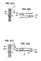
- the metal bellows 3 has crest portions 32 at an outer diameter side and root portions 33 at an inner diameter side, each of which has a sectional shape in the axial direction in U-shape, and curvature radiuses of U-shaped sections 3A of the portions 32 and 33 are identically R 0 in a normal state as shown in Figs. 2 ( 1 ) and 2 (2) .
- the metal bellows 3 is deformed such that the curvature radiuses of the U-shaped sections 3A of the crest portions 32 at an outer diameter side and root portions 33 at an inner diameter side become different, as shown in Figs. 3 ( 1 ) and 3(2) .
- damping ring 34 on the other end of the metal bellows 3 at its outer periphery side, where the metal bellows 3 is connected with the bellows cap 31.
- the damping ring 34 is provided slidingly in contact with the inner peripheral surface of the shell 2 to prevent the metal bellows 3 from winding its way and scratching the inner periphery of the shell 2 when the metal bellows 3 is contracted.
- the bellows cap 31 and metal bellows 3 may be formed separately from each other, or formed integrally. Further, high pressure gas which is to be enclosed in the gas chamber 11 may not only be a single gaseous matter but also include a proper quantity of volume-adjusting liquid.
- An oil port 4 is disposed within the metal bellows 3 at the side of the attachment portion 23.
- One end of the oil port 4 is connected with the shell 2 by welding, and the other end of the oil port 4 has a recess portion 41 formed at the side of the gas plug 21.
- a seal holder 42 formed as a cup-shaped metal fitting is fixedly secured to the oil port 4 at the side facing the gas plug 21 and at the inner periphery side of the recess portion 41 by means of welding, caulking, press-fitting or the like.
- a stopper 43 is provided on the oil port 4 at the side facing the gas plug 21 to contact with the bellows cap 31 to thereby stop the movement of it when the metal bellows 3 is contracted during operation of the accumulator 1.
- the seal holder 42 is configured to have an inner space constituting a chamber for damping pulsation of pressurized liquid flow.
- a seal section 5 is a self-seal type one having a lip portion made of a rubbery elastic body, which is attached to the recess portion 41 by a mechanical fixing means such as press-fitting at the outer periphery side of the seal holder 42, thereby to seal the boundary with the bellows cap 31 and to prevent over adhesion of the metal bellows 3 when the bellows cap 31 is lowered (downward direction in the drawing) to be in contact with the stopper 43.
Landscapes
- Engineering & Computer Science (AREA)
- General Engineering & Computer Science (AREA)
- Mechanical Engineering (AREA)
- Physics & Mathematics (AREA)
- Fluid Mechanics (AREA)
- Supply Devices, Intensifiers, Converters, And Telemotors (AREA)
- Diaphragms And Bellows (AREA)
Claims (1)
- Metallbalgspeicher (1) mit:einer Hülle (2), die einen Anbringabschnitt (23) hat, der an einem Ende ausgebildet ist, um an ein gegebenes System angebracht zu werden, und die einen Gasabdeckstopfen (21) hat, der an dem anderen Ende befestigt ist, um einen Gasbefüllungsanschluss zum Befüllen eines Hochdruckgases zu schließen;einem Metallbalg (3), der in der Lage ist, sich auszudehnen und zusammenzuziehen, und innerhalb der Hülle (2) eingerichtet ist, wobei ein Ende des Metallbalgs fest an der Hülle (2) an der Seite des Anbringabschnitts (23) gesichert ist und ein anderes Ende des Metallbalgs mit einer Balgkappe (31) verbunden ist, sodass ein Inneres der Hülle (2) in eine Außengaskammer (11), in der Hochdruckgas eingeschlossen ist, an der Seite des Gasanschlusses (21) und eine Innenflüssigkeitskammer (12) aufgeteilt ist, zu und von der druckbeaufschlagte Flüssigkeit eingeführt und abgelassen wird, wobei der Metallbalg (3) Kranzabschnitte (32) an einer Außendurchmesserseite und Grundabschnitte (33) an einer Innendurchmesserseite hat, wobei jeder der Abschnitte (32) und (33) einen Querschnitt in der axialen Richtung in einer U-Form hat; undeinem Ölanschluss (4), der innerhalb der Flüssigkeitskammer (12) eingerichtet ist, um den Grad des Zusammenziehens des Metallbalgs (3) zu beschränken; dadurch gekennzeichnet, dassder Metallbalg (3) so aufgebaut ist, dass, wenn Druck in der Flüssigkeitskammer (12) weiter reduziert wird, nachdem die Balgkappe (31) mit dem Ölanschluss (4) in Verbindung gebracht ist, Berührungsflächen (35) an dem Metallbalg (3) ausgebildet werden und ein Krümmungsradius der U-förmigen Teilabschnitte (3A) der Kranzabschnitte (32) an der Außendurchmesserseite reduziert wird, um zusammen mit den Berührungsflächen (35) haarnadelförmige Teilabschnitte (32A) auszubilden, und ein Krümmungsradius der U-förmigen Teilabschnitte (3A) der Grundabschnitte (33) an der Innendurchmesserseite vergrößert wird.
Applications Claiming Priority (2)
| Application Number | Priority Date | Filing Date | Title |
|---|---|---|---|
| JP2006010706A JP4862987B2 (ja) | 2006-01-19 | 2006-01-19 | 金属ベローズ型アキュムレータ |
| PCT/JP2006/325325 WO2007083471A1 (ja) | 2006-01-19 | 2006-12-20 | 金属ベローズ型アキュムレータ |
Publications (3)
| Publication Number | Publication Date |
|---|---|
| EP1975417A1 EP1975417A1 (de) | 2008-10-01 |
| EP1975417A4 EP1975417A4 (de) | 2012-08-29 |
| EP1975417B1 true EP1975417B1 (de) | 2013-10-23 |
Family
ID=38287427
Family Applications (1)
| Application Number | Title | Priority Date | Filing Date |
|---|---|---|---|
| EP06834995.0A Active EP1975417B1 (de) | 2006-01-19 | 2006-12-20 | Metallbalgspeicher |
Country Status (4)
| Country | Link |
|---|---|
| US (1) | US7628175B2 (de) |
| EP (1) | EP1975417B1 (de) |
| JP (1) | JP4862987B2 (de) |
| WO (1) | WO2007083471A1 (de) |
Families Citing this family (27)
| Publication number | Priority date | Publication date | Assignee | Title |
|---|---|---|---|---|
| JP5224323B2 (ja) * | 2007-10-10 | 2013-07-03 | イーグル工業株式会社 | アキュムレータ |
| JP5102576B2 (ja) * | 2007-10-10 | 2012-12-19 | Nok株式会社 | アキュムレータ |
| JP5016453B2 (ja) * | 2007-11-20 | 2012-09-05 | Nok株式会社 | アキュムレータ |
| JP5088823B2 (ja) * | 2008-02-15 | 2012-12-05 | Nok株式会社 | 金属ベローズ式アキュムレータ |
| JP5116153B2 (ja) * | 2008-03-20 | 2013-01-09 | Nok株式会社 | ベローズ式アキュムレータ |
| JP5474333B2 (ja) * | 2008-11-05 | 2014-04-16 | イーグル工業株式会社 | アキュムレータ |
| DE102008061221A1 (de) * | 2008-12-09 | 2010-06-10 | Hydac Technology Gmbh | Hydrospeicher, insbesondere Balgspeicher |
| US7732722B1 (en) | 2009-02-24 | 2010-06-08 | Honeywell International Inc. | Hermetically sealed pressure switch with composite actuation mechanism |
| JP5535743B2 (ja) * | 2009-05-01 | 2014-07-02 | イーグル工業株式会社 | 金属ベローズ |
| DE102010026092A1 (de) * | 2010-07-05 | 2012-01-05 | Robert Bosch Gmbh | Druckspeichervorrichtung zur Verbindung mit einer hydraulischen Anlage |
| WO2012039899A2 (en) * | 2010-09-22 | 2012-03-29 | Limo-Reid, Inc. | Ultra lightweight and compact accumulator |
| JP5715845B2 (ja) * | 2011-02-15 | 2015-05-13 | イーグル工業株式会社 | アキュムレータ |
| JP2012237426A (ja) * | 2011-05-13 | 2012-12-06 | Smc Corp | 真空弁用ベローズ |
| EP2860406B1 (de) * | 2012-06-11 | 2020-01-15 | Eagle Industry Co., Ltd. | Akkumulator |
| JP5932517B2 (ja) * | 2012-06-26 | 2016-06-08 | イーグル工業株式会社 | アキュムレータ |
| US9683583B2 (en) | 2013-08-02 | 2017-06-20 | Eagle Industry Co., Ltd. | Metal bellows |
| JP5798646B2 (ja) * | 2014-02-24 | 2015-10-21 | 日本発條株式会社 | アキュムレータ |
| JP6416875B2 (ja) | 2014-03-11 | 2018-10-31 | イーグル工業株式会社 | アキュムレータ |
| US10473123B2 (en) | 2015-05-29 | 2019-11-12 | Eagle Industry Co., Ltd. | Metal bellows type accumulator |
| FR3060533A1 (fr) * | 2016-12-19 | 2018-06-22 | Safran Aircraft Engines | Accumulateur sur une ligne de carburant d'aeronef |
| CN106523569B (zh) * | 2017-01-12 | 2019-06-25 | 常州万安汽车部件科技有限公司 | 油气减震系统 |
| US10119767B2 (en) * | 2017-02-10 | 2018-11-06 | Hamilton Sundstrand Corporation | Two-phase thermal loop with membrane separation |
| US10295271B2 (en) | 2017-02-10 | 2019-05-21 | Hamilton Sundstrand Corporation | Two-phase thermal loop with rotary separation |
| JP6803271B2 (ja) | 2017-03-13 | 2020-12-23 | 日本発條株式会社 | アキュムレータ |
| DE102017124162A1 (de) * | 2017-10-17 | 2019-04-18 | Boa Balg- Und Kompensatoren-Technologie Gmbh | Metallbalg und Verfahren zum Herstellen eines Metallbalgs |
| DE102021002971A1 (de) * | 2021-06-10 | 2022-12-15 | Hydac Technology Gmbh | Trennelement und Hydrospeicher mit einem solchen Trennelement |
| JP2023140998A (ja) * | 2022-03-23 | 2023-10-05 | 日本発條株式会社 | アキュムレータ |
Family Cites Families (12)
| Publication number | Priority date | Publication date | Assignee | Title |
|---|---|---|---|---|
| US2490513A (en) * | 1947-04-15 | 1949-12-06 | Metallschlauchfabrik Ag | Corrugated tube |
| US4213545A (en) * | 1978-09-20 | 1980-07-22 | Textron, Inc. | Expanding bellows for expulsion tank |
| JPH03244874A (ja) * | 1990-02-22 | 1991-10-31 | Fuji Seiko Kk | 密着高耐圧型金属製ベローズおよびその製造方法 |
| FR2671844B1 (fr) * | 1991-01-17 | 1994-12-30 | Eg G | Soufflet a ondes courbes. |
| FR2703124B1 (fr) * | 1993-03-26 | 1995-07-07 | Ecia Equip Composants Ind Auto | Soufflet elastiquement deformable. |
| JP3692638B2 (ja) * | 1996-07-04 | 2005-09-07 | 日本発条株式会社 | メタルベローズアキュムレータ |
| JPH11226658A (ja) * | 1998-02-19 | 1999-08-24 | Nhk Spring Co Ltd | ダイヤフラム型成形ベローズ及びその製造方法 |
| JP4131130B2 (ja) * | 2002-05-29 | 2008-08-13 | 株式会社アドヴィックス | ベローズ式液圧蓄圧器 |
| JP3906915B2 (ja) * | 2002-07-15 | 2007-04-18 | 株式会社アドヴィックス | 液圧回路 |
| JP3867648B2 (ja) * | 2002-09-19 | 2007-01-10 | 株式会社アドヴィックス | ベローズ式液圧アキュムレータ |
| DE10305000B4 (de) * | 2003-02-07 | 2005-02-03 | Carl Freudenberg Kg | Metallbalgdruckspeicher für hydraulische Systeme |
| JP2005240834A (ja) * | 2004-02-24 | 2005-09-08 | Nok Corp | ベローズ型アキュムレータ |
-
2006
- 2006-01-19 JP JP2006010706A patent/JP4862987B2/ja active Active
- 2006-12-20 EP EP06834995.0A patent/EP1975417B1/de active Active
- 2006-12-20 WO PCT/JP2006/325325 patent/WO2007083471A1/ja active Application Filing
- 2006-12-20 US US12/223,015 patent/US7628175B2/en active Active
Also Published As
| Publication number | Publication date |
|---|---|
| US20090133768A1 (en) | 2009-05-28 |
| EP1975417A4 (de) | 2012-08-29 |
| EP1975417A1 (de) | 2008-10-01 |
| US7628175B2 (en) | 2009-12-08 |
| JP4862987B2 (ja) | 2012-01-25 |
| WO2007083471A1 (ja) | 2007-07-26 |
| JP2007192290A (ja) | 2007-08-02 |
Similar Documents
| Publication | Publication Date | Title |
|---|---|---|
| EP1975417B1 (de) | Metallbalgspeicher | |
| US7770599B2 (en) | Accumulator | |
| JP5102576B2 (ja) | アキュムレータ | |
| JP2008164172A (ja) | 相対運動、特に、モノチューブショックアブソーバのロッドおよび相対ガイディングシートのように直線往復運動する2つの機械的部材の間に挿入する環状シーリングアセンブリ | |
| US6848755B2 (en) | Accumulator | |
| US7318452B2 (en) | Accumulator | |
| EP3306109B1 (de) | Metallbalgartiger akkumulator | |
| JP2007187229A (ja) | 金属ベローズ型アキュムレータ | |
| EP2865898B1 (de) | Akkumulator | |
| JP2009236137A (ja) | 金属ベローズ式アキュムレータ | |
| US7810522B1 (en) | Accumulator | |
| JP5279076B2 (ja) | 金属ベローズ式アキュムレータ | |
| EP3118463B1 (de) | Akkumulator | |
| US10794447B2 (en) | Bump stopper and shock absorber | |
| US10520084B2 (en) | Metal bellows | |
| GB2064652A (en) | Pressure vessels | |
| EP3597932B1 (de) | Akkumulator | |
| EP3591265B1 (de) | Faltenbalg | |
| US20070029710A1 (en) | Accumulator and spacer for accumulator | |
| JP2009092143A (ja) | アキュムレータ | |
| JP5016453B2 (ja) | アキュムレータ | |
| EP3153698B1 (de) | Kraftstoffleistenanordnung | |
| JP2019086059A (ja) | 緩衝器 | |
| US20070024109A1 (en) | Accumulator | |
| JP5116156B2 (ja) | 金属ベローズ式アキュムレータ |
Legal Events
| Date | Code | Title | Description |
|---|---|---|---|
| PUAI | Public reference made under article 153(3) epc to a published international application that has entered the european phase |
Free format text: ORIGINAL CODE: 0009012 |
|
| 17P | Request for examination filed |
Effective date: 20080717 |
|
| AK | Designated contracting states |
Kind code of ref document: A1 Designated state(s): DE |
|
| DAX | Request for extension of the european patent (deleted) | ||
| RBV | Designated contracting states (corrected) |
Designated state(s): DE |
|
| A4 | Supplementary search report drawn up and despatched |
Effective date: 20120727 |
|
| RIC1 | Information provided on ipc code assigned before grant |
Ipc: F16J 3/04 20060101ALI20120723BHEP Ipc: F15B 1/08 20060101AFI20120723BHEP |
|
| RAP1 | Party data changed (applicant data changed or rights of an application transferred) |
Owner name: EAGLE INDUSTRY CO., LTD. |
|
| GRAP | Despatch of communication of intention to grant a patent |
Free format text: ORIGINAL CODE: EPIDOSNIGR1 |
|
| INTG | Intention to grant announced |
Effective date: 20130515 |
|
| GRAS | Grant fee paid |
Free format text: ORIGINAL CODE: EPIDOSNIGR3 |
|
| GRAA | (expected) grant |
Free format text: ORIGINAL CODE: 0009210 |
|
| AK | Designated contracting states |
Kind code of ref document: B1 Designated state(s): DE |
|
| REG | Reference to a national code |
Ref country code: DE Ref legal event code: R096 Ref document number: 602006038992 Country of ref document: DE Effective date: 20131219 |
|
| REG | Reference to a national code |
Ref country code: DE Ref legal event code: R097 Ref document number: 602006038992 Country of ref document: DE |
|
| PLBE | No opposition filed within time limit |
Free format text: ORIGINAL CODE: 0009261 |
|
| STAA | Information on the status of an ep patent application or granted ep patent |
Free format text: STATUS: NO OPPOSITION FILED WITHIN TIME LIMIT |
|
| 26N | No opposition filed |
Effective date: 20140724 |
|
| REG | Reference to a national code |
Ref country code: DE Ref legal event code: R097 Ref document number: 602006038992 Country of ref document: DE Effective date: 20140724 |
|
| PGFP | Annual fee paid to national office [announced via postgrant information from national office to epo] |
Ref country code: DE Payment date: 20231031 Year of fee payment: 18 |