EP1974940B1 - Maschine zum Drucken von Bildern auf Artikeln - Google Patents
Maschine zum Drucken von Bildern auf Artikeln Download PDFInfo
- Publication number
- EP1974940B1 EP1974940B1 EP08153365A EP08153365A EP1974940B1 EP 1974940 B1 EP1974940 B1 EP 1974940B1 EP 08153365 A EP08153365 A EP 08153365A EP 08153365 A EP08153365 A EP 08153365A EP 1974940 B1 EP1974940 B1 EP 1974940B1
- Authority
- EP
- European Patent Office
- Prior art keywords
- ribbon
- rollers
- tensioning
- print head
- machine
- Prior art date
- Legal status (The legal status is an assumption and is not a legal conclusion. Google has not performed a legal analysis and makes no representation as to the accuracy of the status listed.)
- Not-in-force
Links
Images


Classifications
-
- B—PERFORMING OPERATIONS; TRANSPORTING
- B41—PRINTING; LINING MACHINES; TYPEWRITERS; STAMPS
- B41J—TYPEWRITERS; SELECTIVE PRINTING MECHANISMS, i.e. MECHANISMS PRINTING OTHERWISE THAN FROM A FORME; CORRECTION OF TYPOGRAPHICAL ERRORS
- B41J35/00—Other apparatus or arrangements associated with, or incorporated in, ink-ribbon mechanisms
- B41J35/04—Ink-ribbon guides
- B41J35/08—Ink-ribbon guides with tensioning arrangements
Definitions
- the present invention relates to a machine for printing images on articles by means of selective heat transfer of thermofusible ink present on an ink ribbon.
- JP 03 083682 A discloses an ink ribbon cassette comprising a support structure on which a reel for unwinding the ink ribbon and a reel for rewinding the used ribbon are rotatably mounted, between said reels there being defined a path for the ribbon, including a first and a second pair of transmission rollers which are arranged at the corners of two opposite sides of a quadrilateral, downstream of the unwinding reel and upstream of the rewinding reel, respectively; a portion of the ink ribbon which operationally passes between said pairs of rollers being intended to be acted upon by a thermal print head of a printing machine wherein the ink ribbon cassette is used; the ribbon cassette also comprising a first and second diverting device including respective diverting rollers each movable, when the cassette is opened for replacing the ink ribbon, along a trajectory which intersects the path of the ribbon between the two transmission rollers of each pair; the diverting devices having a first condition, when the cassette is opened, where the diverting rollers are arranged in a disengaged
- One object of the present invention is to provide an improbe printing machine in which the operation of positioning and/or replacing the ink ribbon is particularly easy.
- the tensioning rollers of the tensioning devices are supported by respective arms mounted pivotably on the support structure about respective fixed axes perpendicular to the path of the ink ribbon.
- the resilient means associated with the tensioning devices may comprise a first and a second recall spring which are associated with each tensioning roller and are preferably connected to the associated pivoting arms.
- the resilient means associated with the tensioning devices may comprise a single spring tending to recall towards each other said tensioning rollers or the associated pivoting arms.
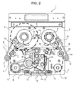
- 1 denotes overall a machine according to the present invention for printing images on articles (not shown) by means of selective heat transfer of thermo fusible ink from an ink ribbon R ( Figures 1 , 2 and 5 ).
- the machine 1 comprises a support structure 2 which houses, rotatably mounted in a manner known per se, a reel or spool 3 for unwinding the ink ribbon R and a reel or spool 4 for rewinding the used ribbon R.
- the rewinding reel 4 is motor-driven so as to impart to the ribbon R, during operation, a movement in the direction indicated by the arrows F in Figure 5 .
- FIG. 5 An operative path shown in Figure 5 is defined for the ribbon R between the reels or spools 3 and 4.
- the ribbon R passes around a first transmission roller 5 and then passes around a tensioning roller 7 mounted on a first pivoting arm 9 which is hinged with the support structure 2 about a shaft 10 which is essentially perpendicular to the path of the ribbon R.
- a helical spring 11 is connected to the pivoting arm 10, while the other end thereof is connected to the support structure 2. With reference to Figure 5 , the spring 11 tends to recall the pivoting arm 9 away from the transmission roller 5, which is instead rotatable about a fixed shaft.
- the ribbon R passes around a further transmission roller 6 which is also rotatable about a shaft which is stationary and, preferably, motor-driven.
- the ribbon R Downstream of the roller 6 the ribbon R passes into the bottom area of the support structure 2 to which a frame 12 is fixed, said frame having, extending therein, two idle rollers 13 and 14 which are parallel and spaced from each other and which define between them an opening indicated by 15 (see Figures 3 and 5 ).
- the ink ribbon R passes onto the roller 13 and then around the active bottom edge of a thermal print head 16, which is of the type known per se. Downstream of this print head, the ribbon R travels back up towards the transmission roller 18, passing over the roller 14 mounted on the bottom frame 12.
- the ribbon R After travelling around the roller 18, the ribbon R passes around a tensioning roller 19 mounted on a pivoting arm 20 which is similar to the arm 9 described above.
- the arm 20 is mounted pivotably about a fixed shaft 21 which is parallel to the shaft 10 of the other pivoting arm 9.
- the ribbon R Downstream of the tensioning roller 19, the ribbon R passes around a further transmission roller 22 rotatable about a fixed shaft and finally reaches the rewinding reel or spool 4.
- the two pairs of transmission rollers 5, 6 and 18, 22 are arranged at the corners of two opposite sides of a quadrilateral and the thermal print head 16 is arranged close to the portion of the ink ribbon R which operationally passes between these pairs of rollers.
- a shaft 24 is mounted in the middle region of the support structure 2 ( Figure 3 ) and has, integral therewith, a cam member 25 ( Figures 3 and 5 ) which extends on the front side of the machine and to which an operating handle 26 is connected at the front.
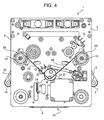
- the shaft 24 On the rear of the support structure 2 ( Figure 4 ) the shaft 24 has an eccentric lug 27 acting as a transmission for an unextendable belt 28, the opposite ends of which are fastened to the periphery of corresponding rollers 29 and 30 which are rotationally integral with the pivoting arms 9 and 20 about the corresponding shafts 10 and 21.
- the arrangement is such that the handle 26 is able to be arranged in a first position, shown in Figures 1 to 3 and, in broken lines, in Figure 5 .
- the shaft 24 is arranged in the angular position which is visible in Figure 4 and where it tensions the belt 28 downwards, keeping consequently the pivoting arms 9 and 20 in the splayed position which is shown in Figures 1 to 4 and, in broken lines, in Figure 5 .
- the tensioning rollers 7 and 19 are arranged in a disengaged position where they extend externally and at a distance from the path of the ribbon R, between the pair of transmission rollers 5, 6 and the pair of transmission rollers 18, 22, respectively.
- the thermal print head 16 is mounted so as to be vertically movable in the support structure 2, between a lowered or working position ( Figure 5 ), where it engages with the section of the ribbon R which passes close to the frame 12, and a raised or disengaged position ( Figures 2 and 3 ), where it extends above the section of ribbon R which extends between the transmission rollers 6 and 18.
- the head 16 is mounted on a unit denoted overall by 32 which is vertically displaceable and provided at the top with a shaped appendage 33 cooperating with the cam formation 25 which is integral with the shaft 24 and the handle 26 ( Figures 3 and 5 ).
- a pair of helical springs 34 tends to recall the unit 32 upwards and keep the shaped appendage 33 of this unit engaged with the surface of the cam formation 25 integral with the shaft 24 and the handle 26.
- the arrangement is such that when the handle 26 passes from the position shown in Figures 1 to 3 into the position shown in solid lines in Figure 5 , the assembly 32 is forced to move downwards against the recall action exerted by the springs 34 until the print head 16 engages with the portion of the ribbon R which extends between the rollers 13 and 14 of the frame 12.
Landscapes
- Electronic Switches (AREA)
- Impression-Transfer Materials And Handling Thereof (AREA)
- Handling Of Continuous Sheets Of Paper (AREA)
Claims (6)
- Maschine (1) zum Drucken von Bildern auf Artikel mittels selektivem Wärmetransfer von durch Wärme verflüssigbarer Tinte von einem Farbband (R), umfassend eine Unterstützungsstruktur (2), an welcher eine Spule (3) zum Abwickeln des Farbbands (R) und eine Spule (4) zum Rückwickeln des verwendeten Bands (R) drehbar angebracht sind, wobei zwischen den Spulen (3, 4) ein Pfad für das Band (R) definiert ist, umfassend ein erstes und ein zweites Paar von Übertragungsrollen (5, 6; 18, 22), welche an den Ecken von zwei gegenüberliegenden Seiten eines Vierecks, der Abwickelspule (3) nachgeordnet bzw. der Rückwickelspule (4) vorgeordnet, angeordnet sind, wobei ein Thermodruckkopf (16) in der Struktur angebracht ist und in der Lage ist, auf einen Abschnitt des Farbbandes (R) zu wirken, welcher im Betrieb zwischen den Paaren von Rollen (5, 6; 18, 22) hindurch passiert,
wobei die Maschine (1) auch eine erste und eine zweite Spannvorrichtung (7, 9, 11; 19, 20, 23) umfasst, welche jeweilige Spannrollen (7, 19) umfassen, von denen jede im Betrieb entlang einer Bahn beweglich ist, die den Pfad des Bandes (R) zwischen den zwei Übertragungsrollen (5, 6; 18, 22) von jedem Paar schneidet,
wobei die Maschine auch Schaltmittel (24-26) umfasst, welche mit den Spannungsrollen (7, 19) der Spannungsvorrichtungen (7, 9, 11; 19, 20, 23) verbunden sind und in der Lage sind, selektiv eingestellt zu werden, auf:- einen ersten Zustand, in welchem die Spannungsrollen (7, 19) in einer Nichteingriffposition angeordnet sind, in der sie sich nach außen erstrecken, und mit einem Abstand von dem Pfad des Bandes (R), zwischen dem entsprechenden Paar von Übertragungsrollen (5, 6; 18, 22) und- einen zweiten Zustand, in welchem die Spannungsrollen (7, 19) frei sind, unter der Wirkung von zugeordneten Federmitteln (11, 23; 40) eine Betriebsposition einzunehmen, in welcher das Band (R) zwischen dem entsprechenden Paar von Übertragungsrollen (5, 26; 18, 22) in Eingriff steht, dazu neigend, zwischen den Rollen dieses Paars eine Schleife des Bands (R) zu bilden,wobei der Druckkopf (16) beweglich in der Unterstützungsstruktur (2) zwischen einer Position, in der er mit dem Band in Eingriff steht, und einer Position, in der er mit einem Abstand angeordnet ist und nicht mit dem Band (R) in Eingriff steht, angebracht ist, wobei die Schaltmittel (24-26) mit dem Druckkopf (16) verbunden sind, so dass, wenn die Schaltmittel (24-26) den oben erwähnten ersten bzw. zweiten Zustand einnehmen, der Druckkopf (16) in der Position angeordnet ist, in der er nicht mit dem Farbband (R) in Eingriff steht, bzw. in der Position, in der er damit in Eingriff steht. - Maschine nach Anspruch 1, wobei die Spannungsrollen (7, 19) von jeweiligen Armen (9, 20) unterstützt werden, die an der Unterstützungsstruktur (2) um jeweilige Achsen (10, 21) orthogonal zu der Bahn des Bandes (R) schwenkbar angebracht sind.
- Maschine nach Anspruch 1 oder 2, wobei die Federmittel, die der ersten und der zweiten Spannvorrichtung (7, 9, 11; 19, 20, 23) zugeordneten sind, jeweilige separate Federn (11, 23) umfassen.
- Maschine nach Anspruch 1 oder 2, wobei die Federmittel, die den Spannvorrichtungen (7, 9, 11; 19, 20, 23) zugeordneten sind, eine einzige Feder (40) umfassen, welche die Spannvorrichtungen miteinander verbindet.
- Maschine nach einem der vorhergehenden Ansprüche, wobei die Schaltmittel (24-26) mit den Spannvorrichtungen (7, 9, 11; 19, 20, 23) mittels eines Nockenmechanismus (24, 27-30) verbunden sind.
- Maschine nach Anspruch 4, wobei die Schaltmittel (24-26) mit dem Druckkopf (16) mittels eines (weiteren) Nockenmechanismus (25, 33) verbunden sind.
Applications Claiming Priority (1)
| Application Number | Priority Date | Filing Date | Title |
|---|---|---|---|
| IT000230A ITTO20070230A1 (it) | 2007-03-30 | 2007-03-30 | Macchina per la stampa di immagini su articoli |
Publications (3)
| Publication Number | Publication Date |
|---|---|
| EP1974940A2 EP1974940A2 (de) | 2008-10-01 |
| EP1974940A3 EP1974940A3 (de) | 2010-02-03 |
| EP1974940B1 true EP1974940B1 (de) | 2012-02-01 |
Family
ID=39555710
Family Applications (1)
| Application Number | Title | Priority Date | Filing Date |
|---|---|---|---|
| EP08153365A Not-in-force EP1974940B1 (de) | 2007-03-30 | 2008-03-27 | Maschine zum Drucken von Bildern auf Artikeln |
Country Status (3)
| Country | Link |
|---|---|
| EP (1) | EP1974940B1 (de) |
| ES (1) | ES2379477T3 (de) |
| IT (1) | ITTO20070230A1 (de) |
Cited By (1)
| Publication number | Priority date | Publication date | Assignee | Title |
|---|---|---|---|---|
| US8801306B2 (en) | 2010-03-16 | 2014-08-12 | Markem-Imaje Industries Limited | Printing apparatus and method of printing with ribbon tension adjustment using movable ribbon guide members |
Families Citing this family (1)
| Publication number | Priority date | Publication date | Assignee | Title |
|---|---|---|---|---|
| IT201600081050A1 (it) * | 2016-08-02 | 2018-02-02 | Eidos S R L | Macchina per la stampa di immagini su articoli mediante un rullo a trasferimento termico. |
Family Cites Families (5)
| Publication number | Priority date | Publication date | Assignee | Title |
|---|---|---|---|---|
| JPS6021287A (ja) * | 1983-07-15 | 1985-02-02 | Tokyo Electric Co Ltd | プリンタのインキリボン案内装置 |
| JP2786897B2 (ja) * | 1989-08-28 | 1998-08-13 | アルプス電気株式会社 | リボンカセット |
| JP3325951B2 (ja) * | 1993-05-13 | 2002-09-17 | 日本電産コパル株式会社 | プリンタ装置 |
| JP2001260506A (ja) * | 2000-03-14 | 2001-09-25 | Alps Electric Co Ltd | 熱転写プリンタ |
| DE602005023035D1 (de) * | 2004-10-08 | 2010-09-30 | Yuyama Mfg Co Ltd | Arzneimittelzufuhrvorrichtung |
-
2007
- 2007-03-30 IT IT000230A patent/ITTO20070230A1/it unknown
-
2008
- 2008-03-27 EP EP08153365A patent/EP1974940B1/de not_active Not-in-force
- 2008-03-27 ES ES08153365T patent/ES2379477T3/es active Active
Cited By (1)
| Publication number | Priority date | Publication date | Assignee | Title |
|---|---|---|---|---|
| US8801306B2 (en) | 2010-03-16 | 2014-08-12 | Markem-Imaje Industries Limited | Printing apparatus and method of printing with ribbon tension adjustment using movable ribbon guide members |
Also Published As
| Publication number | Publication date |
|---|---|
| ES2379477T3 (es) | 2012-04-26 |
| ITTO20070230A1 (it) | 2008-09-30 |
| EP1974940A2 (de) | 2008-10-01 |
| EP1974940A3 (de) | 2010-02-03 |
Similar Documents
| Publication | Publication Date | Title |
|---|---|---|
| EP1038687B1 (de) | Drucker | |
| JP4992657B2 (ja) | ロール紙供給装置およびロール紙プリンタ | |
| EP0311982B1 (de) | Thermodrucker | |
| EP0311981A2 (de) | Nach dem Übertragungsprinzip arbeitender Thermodrucker | |
| JP5869708B2 (ja) | サーマルプリンタ | |
| JP5272158B2 (ja) | サーマルプリンタ | |
| EP1974940B1 (de) | Maschine zum Drucken von Bildern auf Artikeln | |
| US20050200681A1 (en) | Paper discharge mechanism for a printer, and a printer | |
| US4669896A (en) | Actuating mechanism for printing head of printing machine | |
| JP5063482B2 (ja) | プリンタ | |
| JP2013052612A (ja) | プリンタ | |
| JP4830416B2 (ja) | ロール紙プリンタ | |
| JP5680694B2 (ja) | サーマルプリンタ | |
| JP5272150B2 (ja) | サーマルプリンタ | |
| JP2009285999A (ja) | プリンタ | |
| JP6966243B2 (ja) | プリンタ | |
| JP4016585B2 (ja) | プリンタ | |
| JPH037173Y2 (de) | ||
| JPS6168275A (ja) | 転写型感熱記録装置 | |
| JP2004167970A (ja) | ラインサーマルプリンタ | |
| JP3815125B2 (ja) | ロール状のウエッブの弛み除去装置 | |
| JP4652758B2 (ja) | 熱転写プリンターのリボンカセット装置 | |
| JP7334488B2 (ja) | 印刷装置 | |
| JP3936782B2 (ja) | 印刷装置 | |
| JP2009179009A (ja) | サーマルプリンタ |
Legal Events
| Date | Code | Title | Description |
|---|---|---|---|
| PUAI | Public reference made under article 153(3) epc to a published international application that has entered the european phase |
Free format text: ORIGINAL CODE: 0009012 |
|
| AK | Designated contracting states |
Kind code of ref document: A2 Designated state(s): AT BE BG CH CY CZ DE DK EE ES FI FR GB GR HR HU IE IS IT LI LT LU LV MC MT NL NO PL PT RO SE SI SK TR |
|
| AX | Request for extension of the european patent |
Extension state: AL BA MK RS |
|
| PUAL | Search report despatched |
Free format text: ORIGINAL CODE: 0009013 |
|
| AK | Designated contracting states |
Kind code of ref document: A3 Designated state(s): AT BE BG CH CY CZ DE DK EE ES FI FR GB GR HR HU IE IS IT LI LT LU LV MC MT NL NO PL PT RO SE SI SK TR |
|
| AX | Request for extension of the european patent |
Extension state: AL BA MK RS |
|
| 17P | Request for examination filed |
Effective date: 20100728 |
|
| 17Q | First examination report despatched |
Effective date: 20100826 |
|
| AKX | Designation fees paid |
Designated state(s): DE ES FR GB |
|
| GRAP | Despatch of communication of intention to grant a patent |
Free format text: ORIGINAL CODE: EPIDOSNIGR1 |
|
| GRAS | Grant fee paid |
Free format text: ORIGINAL CODE: EPIDOSNIGR3 |
|
| GRAA | (expected) grant |
Free format text: ORIGINAL CODE: 0009210 |
|
| AK | Designated contracting states |
Kind code of ref document: B1 Designated state(s): DE ES FR GB |
|
| REG | Reference to a national code |
Ref country code: GB Ref legal event code: FG4D |
|
| REG | Reference to a national code |
Ref country code: DE Ref legal event code: R096 Ref document number: 602008013011 Country of ref document: DE Effective date: 20120329 |
|
| REG | Reference to a national code |
Ref country code: ES Ref legal event code: FG2A Ref document number: 2379477 Country of ref document: ES Kind code of ref document: T3 Effective date: 20120426 |
|
| PLBE | No opposition filed within time limit |
Free format text: ORIGINAL CODE: 0009261 |
|
| STAA | Information on the status of an ep patent application or granted ep patent |
Free format text: STATUS: NO OPPOSITION FILED WITHIN TIME LIMIT |
|
| 26N | No opposition filed |
Effective date: 20121105 |
|
| REG | Reference to a national code |
Ref country code: DE Ref legal event code: R097 Ref document number: 602008013011 Country of ref document: DE Effective date: 20121105 |
|
| REG | Reference to a national code |
Ref country code: FR Ref legal event code: PLFP Year of fee payment: 9 |
|
| REG | Reference to a national code |
Ref country code: FR Ref legal event code: PLFP Year of fee payment: 10 |
|
| REG | Reference to a national code |
Ref country code: ES Ref legal event code: PC2A Owner name: EIDOS S.R.L. Effective date: 20180122 |
|
| REG | Reference to a national code |
Ref country code: DE Ref legal event code: R081 Ref document number: 602008013011 Country of ref document: DE Owner name: EIDOS S.R.L., IT Free format text: FORMER OWNER: EIDOS S.P.A., CHIERI, TURIN/TORINO, IT |
|
| REG | Reference to a national code |
Ref country code: FR Ref legal event code: PLFP Year of fee payment: 11 |
|
| REG | Reference to a national code |
Ref country code: FR Ref legal event code: CD Owner name: EIDOS S.P.A., IT Effective date: 20180227 |
|
| PGFP | Annual fee paid to national office [announced via postgrant information from national office to epo] |
Ref country code: GB Payment date: 20220321 Year of fee payment: 15 Ref country code: DE Payment date: 20220322 Year of fee payment: 15 |
|
| PGFP | Annual fee paid to national office [announced via postgrant information from national office to epo] |
Ref country code: FR Payment date: 20220331 Year of fee payment: 15 |
|
| PGFP | Annual fee paid to national office [announced via postgrant information from national office to epo] |
Ref country code: ES Payment date: 20220401 Year of fee payment: 15 |
|
| REG | Reference to a national code |
Ref country code: DE Ref legal event code: R119 Ref document number: 602008013011 Country of ref document: DE |
|
| GBPC | Gb: european patent ceased through non-payment of renewal fee |
Effective date: 20230327 |
|
| PG25 | Lapsed in a contracting state [announced via postgrant information from national office to epo] |
Ref country code: GB Free format text: LAPSE BECAUSE OF NON-PAYMENT OF DUE FEES Effective date: 20230327 |
|
| PG25 | Lapsed in a contracting state [announced via postgrant information from national office to epo] |
Ref country code: GB Free format text: LAPSE BECAUSE OF NON-PAYMENT OF DUE FEES Effective date: 20230327 Ref country code: FR Free format text: LAPSE BECAUSE OF NON-PAYMENT OF DUE FEES Effective date: 20230331 Ref country code: DE Free format text: LAPSE BECAUSE OF NON-PAYMENT OF DUE FEES Effective date: 20231003 |
|
| REG | Reference to a national code |
Ref country code: ES Ref legal event code: FD2A Effective date: 20240506 |
|
| PG25 | Lapsed in a contracting state [announced via postgrant information from national office to epo] |
Ref country code: ES Free format text: LAPSE BECAUSE OF NON-PAYMENT OF DUE FEES Effective date: 20230328 |
|
| PG25 | Lapsed in a contracting state [announced via postgrant information from national office to epo] |
Ref country code: ES Free format text: LAPSE BECAUSE OF NON-PAYMENT OF DUE FEES Effective date: 20230328 |