EP1974367B1 - Lampe à décharge à haute pression munie de lamelles de refroidissement montées à l'extrémité de la cuve de décharge - Google Patents
Lampe à décharge à haute pression munie de lamelles de refroidissement montées à l'extrémité de la cuve de décharge Download PDFInfo
- Publication number
- EP1974367B1 EP1974367B1 EP07703905A EP07703905A EP1974367B1 EP 1974367 B1 EP1974367 B1 EP 1974367B1 EP 07703905 A EP07703905 A EP 07703905A EP 07703905 A EP07703905 A EP 07703905A EP 1974367 B1 EP1974367 B1 EP 1974367B1
- Authority
- EP
- European Patent Office
- Prior art keywords
- discharge vessel
- discharge lamp
- pressure discharge
- lamp according
- laminates
- Prior art date
- Legal status (The legal status is an assumption and is not a legal conclusion. Google has not performed a legal analysis and makes no representation as to the accuracy of the status listed.)
- Expired - Fee Related
Links
Images


Classifications
-
- H—ELECTRICITY
- H01—ELECTRIC ELEMENTS
- H01J—ELECTRIC DISCHARGE TUBES OR DISCHARGE LAMPS
- H01J61/00—Gas-discharge or vapour-discharge lamps
- H01J61/02—Details
- H01J61/52—Cooling arrangements; Heating arrangements; Means for circulating gas or vapour within the discharge space
- H01J61/523—Heating or cooling particular parts of the lamp
-
- H—ELECTRICITY
- H01—ELECTRIC ELEMENTS
- H01J—ELECTRIC DISCHARGE TUBES OR DISCHARGE LAMPS
- H01J61/00—Gas-discharge or vapour-discharge lamps
- H01J61/82—Lamps with high-pressure unconstricted discharge having a cold pressure > 400 Torr
- H01J61/827—Metal halide arc lamps
Definitions
- the invention relates to a high-pressure discharge lamp according to the preamble of claim 1.
- Such lamps are in particular high-pressure discharge lamps with a ceramic discharge vessel for general lighting.
- These are, in particular, metal halide lamps or else sodium high-pressure lamps or high-pressure mercury lamps.
- EP 315 261 discloses a sodium high-pressure discharge lamp in which the bulb of the discharge vessel is made of ceramic. At the ends of the cylindrical discharge vessel fin-like extensions are attached, which serve the heat dissipation.
- the GB 2 281 148 , the JP-A 03-004436 and the JP-A 08-250071 describe discharge vessels made of quartz glass, which have unevennesses or outgrowths at various points for various reasons.
- the object of the present invention is to provide a high-pressure discharge lamp whose color spread is significantly reduced compared to previous lamps.
- the high-pressure discharge lamp with a ceramic discharge vessel has a central part and two ends which are closed by tailpipes, wherein electrodes are anchored in the tailpipes, which extend into the discharge volume enveloped by the discharge vessel, wherein a filling containing metal halides or metals in the Discharge volume is housed.
- fin-like lamellae which extend radially outward are seated at the ends. It is the surface of the lamellae is generally arranged predominantly in a region which lies behind a line away from discharge, which is determined by the projection of the tip of the electrode onto the inner surface of the discharge vessel.
- the arrangement of the lamellae is preferably rotationally symmetrical to each other, in particular with a three- to eight-fold Symmetry.
- the shape of the slats may be substantially similar, but need not.
- two sets of lamellae may be alternately used, for an eightfold symmetry, four each of a kind.
- the invention is particularly suitable for highly loaded metal halide lamps in which the ratio between the inner length and the maximum inner diameter of the discharge vessel, the so-called aspect ratio, is between 1.0 and 8.0, preferably at least 1.5. Limits are included.
- the width of the lamellae is of the order of the wall thickness of the central part of the discharge vessel, and in the case of constant width in particular at most 50%, preferably at most 25%, deviates from this wall thickness.
- the tailpipes are advantageously designed as capillaries. But you can also run differently, see for example DE-A 197 27 429 where a cermet pin is used.
- the invention is also applicable to plug technologies, wherein the slats either sit on the discharge vessel, or on the separate plug part, or can sit on both bodies slats.
- the lamellae have two broad sides and a narrow side, the narrow side pointing radially outward. These sides together define the surface of the lamella.
- the narrow side can be bevelled and in particular be provided with a coating.
- the coating should be highly viscous. Suitable materials are especially graphite or carbon, so other carbon modifications such as DLC (diamond-like carbon).
- the cooling behavior can also be controlled by covering a part of the tailpipe, in particular a part of the lamella like the narrow side, with a coating of high emissivity. It is also possible to use a coating on the tailpipe without simultaneous use of a lamellar projection at this point.
- the material of the piston A1203 in particular PCA, or any other conventional ceramics such as AlON or AIN can be used.
- the choice of filling is subject to no particular restriction.
- discharge vessels or burners for high-pressure lamps with approximately uniform wall thickness distribution and slim-running end shapes exhibit, in some cases, high color scattering due to the strong distribution of the metal halide filling in the interior of the discharge vessel.
- the charge in the discharge-away region condenses behind the line defined by projection of the electrode tip onto the inner burner surface.
- the filling position on a zone of the surface in the interior of the discharge vessel, which corresponds to a narrow temperature range, and in the residual volumes of -eventuell-existing capillaries into is not sufficiently accurately adjustable.
- fins or lamellae to the discharge vessel, the effect of which predominantly occurs in an area which lies behind the line which is determined by projecting the electrode tip onto the inner burner surface.
- predominantly means that at least two-thirds of the surface of the fins is mounted in an area which is behind the line away from discharge, which is determined by projection of the electrode tip on the wall of the discharge vessel.
- Previous discharge vessels often have a shape with increased wall thickness at the end surfaces, eg in cylindrical burner shapes, thereby creating an enlarged end surface.
- Another problem is the increased by the wall thickness-dependent specific emission coefficient of the ceramic radiation of IR radiation during operation of the discharge vessel in the evacuated or gas-filled outer envelope.
- the transition of the discharge vessel in which the arc discharge burns is meant to the end forms containing the electrode structures for electrical or electromagnetic line coupling.
- Essential is the enlargement of the surface by integrally formed in the transition region to the tail pipe wing-like or fin-like formations, preferably with longitudinal alignment parallel to the axis with at least threefold symmetry and a maximum loved tech tech symmetry of the distribution around the circumference. In particular, they are slats.
- the fin-like molding areas may be substantially smooth surfaces or be formed on the surface faceted.
- the facet regions can be delimited over the entire surface area of the lamella and have a defined orientation relative to the axis and to the center of gravity of the discharge vessel.
- NIR near infrared
- the coating should preferably be applied in the region of the transition between the end of the discharge vessel and tailpipe. In particular, this also applies to the tailpipe alone, where the coating can be applied without a lamella.
- High-temperature-resistant coatings with hemispherical emission coefficients ⁇ are suitable as coating materials.
- graphite mixtures of Al2O3 with graphite, mixtures of Al2O3 with carbides of the metals Ti, Ta, Hf, Zr, as well as of semi-metals such as Si.
- mixtures which additionally contain other metals for adjusting any desired electrical conductivity are also suitable.
- both measures can be suitably combined with each other, so that part of the surface radiation increase takes place via an enlargement of the surface by fins and at the same time a part by the coating of parts of these fins or the adjacent colder tailpipe areas.
- the total mass of the discharge vessel increases only insignificantly by this type of fins and thus remains below a critical value that would adversely affect the start-up behavior of the lamp when ignited. There is thus a sophisticated compromise between good ignition and effective cooling.
- This measure allows a very high color stability under the conscious acceptance of a bad isotherm. This is done in departure from the previous objective of the best possible isotherm and allows the zone of condensation of the filling to be determined exactly by deliberately designing a temperature gradient.
- the area of the lamellae is optically transparent or at least translucent. If possible, this should also be the goal for areas with coating. To approximate this goal, the solid angle below which the areas of coating appear from the center of the lamp is minimized as much as possible. Because the coating absorbs radiation and therefore costs efficiency. For this reason, the coating should be applied to inclined surfaces of the slats, since then from the center of their solid angle smaller appears. This applies in particular to the narrow side of the slats.
- An alternative is to place the coating as far back as possible on the lamella and / or the tailpipe, since this also reduces the effectively shaded solid angle. In this way, an optimal value of the cooling can be achieved while maintaining optimum efficiency.
- Particularly effective coatings are graphite and TiC.
- a control means of the cooling effect is also the maximum height of the blade, especially if it attaches to the discharge vessel, since depending on the approach height, the discharge takes place from a different temperature level.
- a particular advantage of such integral lamellae is that they are particularly effective at cooling compared to separate lids, and that they are easy to manufacture using modern manufacturing techniques such as injection molding, slip casting or rapid prototyping.
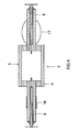
- FIG. 1 It consists of a tubular discharge vessel 2 made of ceramic, in which two electrodes are inserted (not visible).
- the discharge vessel has a central part 5 and two ends 4 at the ends sit two tailpipes 6, which are designed here as capillaries.
- the discharge vessel and the tailpipes are integrally made of a material such as PCA.
- the discharge vessel 2 is surrounded by an outer bulb 7, which terminates a base 8.
- the discharge vessel 2 is supported in the outer bulb by means of a rack including a short and long power supply 11a and 11b.
- a rack including a short and long power supply 11a and 11b.
- At the tail pipes 6 are each slats 10 which extend like a fins radially outward.
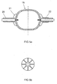
- FIG. 2 shows a plan view of the region of a tailpipe 6.
- the fins 10 have two broad sides 12 and a narrow side 13.
- the fins are distribuvilleig evenly distributed around the tailpipe.
- the fins have a maximum height of about half the maximum height of the central part of the discharge vessel.
- FIG. 3 shows a discharge vessel 2, wherein in the left-hand embodiment, the fins 15 branch off from approximately the maximum height of the end of the discharge vessel and maintain the height. In the right-hand embodiment, the mass of the blade is significantly lower by the maximum height of the blade with increasing distance from the end 4 decreases evenly.
- FIG. 4 shows on the left possibility to effect the cooling only by a coating 16 which completely surrounds the tailpipe 6 like a cuff in its middle part.
- a type of lamella 17 is shown, which is located only on the tailpipe 6 itself and does not extend further to the discharge vessel 2, which is here separate from the capillary.
- the lamella 17 is here shaped like a circle segment.
- FIG. 5 shows in the left embodiment, a discharge vessel 19 with a short tailpipe 20 and very short fins 21, but a total of eight fins are used.
- FIG. 5 further shows in the right embodiment of an arrangement in which these slats additionally a rotationally symmetric. Coating 22 is used after the fins.
- Further embodiments are those with a higher numbering than 8, in particular up to 16.
- the number of fins does not have to be even, it can also be odd, for example five fins.
- Another embodiment is characterized in that differently designed groups of lamellae are used, for example two groups on a tailpipe whose width and height are different and which alternate.
- Each fin or fin has a given maximum height that extends radially to the axis of the discharge vessel and a maximum length that extends axially and a maximum width. All three sizes can have a constant value, but they usually vary so that they are optimally adapted to the needs.
- the height H of the fin or lamella may vary from a fraction, in particular one tenth, of the difference DF between half the maximum outer diameter of the discharge vessel and the half diameter of the capillary up to twice, in particular 1.4 times, particularly preferably to the simple, this difference DF range. So 1/10 DF ⁇ H ⁇ 2 DF. Preferably, 1/5 DF ⁇ H ⁇ 1.4 DF.
- the fins may also be stepped, that is, their height H varies in steps along the length L.
- the width B of the fin is often constant and usually ranges from 0.2 to 1.5 mm.
- a second preferred embodiment is a radially outwardly decreasing width.
- an outwardly increasing width wherein in particular the arc length BL of the width B remains constant.
- a typical arc length BL is 1/10 of the circumference U of the tailpipe down to 1/50 U.
- Another shape of the width of the fin is triangular or in particular trapezoidal, seen in cross section.
- FIG. 7 shows a discharge vessel 25 with stepped blades 27, so that the height H of the blade changes abruptly.
- the definition of the total length GL is shown here.
- FIG. 8 shows a cylindrical discharge vessel 30 with stepped blades 26, in which the fins extend over the entire length of the tail pipe.
- a lower part 26a of the blades is pulled to the end of the discharge vessel, the height of the blades continues to increase in two stages.
- Part 26b has about 50% of the height corresponding to the diameter of the discharge vessel and part 26c has 100% of the height of the diameter of the discharge vessel.
- FIG. 9 shows a cylindrical discharge vessel 30, in which the entire length of the discharge vessel is coated with fins 35.
- FIG. 10 shows a representation of the end 36 of a discharge vessel, which is closed by a separate plug 37.
- the blade 38 here has the shape of a fin, which attaches just behind the line PL and then extends approximately to the approach of the tail pipe 39. Small fins 40 are additionally arranged on the plug 37.
- the term projection line PL at the tip of the electrode 41 is explained in this figure.
- the essence of the invention resides in that at least at one end of the discharge vessel there are fin-like fins, as shown here as 38, which extend radially outwards in their height H, the surface of the fins is arranged predominantly in a region which is located away from discharge behind a line which is determined by the projection of the tip of the electrode on the inner surface of the discharge vessel. Preferably, this proportion is at least two-thirds. But it can be up to 100%.
- the fin can only extend between the projection line PL and the projection AA of the tailpipe, where it exerts the highest effect, or extends further back to a part or the entire length of the tailpipe. But it can also be located only in the tailpipe.
- the dashed lines show possible embodiments of the fin.
- FIG. 11 shows a scheme for explaining the concepts of height H, width B and length L of the slats.
- variable size of the dimensions H, B and L in each case a maximum height, width or length is meant.
Landscapes
- Vessels And Coating Films For Discharge Lamps (AREA)
- Discharge Lamps And Accessories Thereof (AREA)
Claims (10)
- Lampe ( 1 ) à décharge à haute pression ayant une enceinte ( 2 ) de décharge en céramique comprenant une partie ( 5 ) centrale et deux extrémités ( 4 ), où sont placées deux tubes ( 6, 39 ) d'extrémité, des électrodes étant ancrées dans les tubes d'extrémité, en s'étendant dans le volume de décharge enveloppé par l'enceinte de décharge un remplissage qui contient des métaux et/ou des halogénures métalliques étant logé dans le volume de décharge, dans laquelle au moins sur une extrémité ( 4 ) sont placées des lamelles ( 15 ) de type en nageoire qui s'étendent dans leur hauteur H radialement vers l'extérieur, la surface des lamelles étant disposées dans une zone qui se trouve, en étant éloignée de la décharge, derrière un plan, passant par la pointe de l'électrode et perpendiculaire à un axe longitudinal de la lampe, et caractérisée en ce que les lamelles ( 15 ) et l'ensemble ( 2 ) de décharge sont intégralement en A1203, AlON ou AlN.
- Lampe à décharge à haute pression suivant la revendication 1, caractérisée en ce que l'agencement de lamelles ( 15 ) est à symétrie de répétition, en ayant notamment une symétrie d'ordre trois à d'ordre huit.
- Lampe à décharge à haute pression suivant la revendication 2, caractérisée en ce que la forme des lamelles ( 15 ) est sensiblement de même type ou est de même type par groupe.
- Lampe à décharge à haute pression suivant la revendication 1, caractérisée en ce que l'épaisseur des parois des lamelles ( 15 ) correspond à peu près à l'épaisseur des parois de la partie ( 5 ) centrale de l'enceinte de décharge et s'en écarte en fait notamment au plus de 50 %.
- Lampe à décharge à haute pression suivant la revendication 1, caractérisée en ce que les tubes d'extrémité sont réalisés sous la forme de tubes ( 6 ) capillaires.
- Lampes à décharge à haute pression suivant la revendication 1, caractérisée en ce que les lamelles ont deux grands côtés et un petit côté, le petit côté étant à l'extérieur radialement.
- Lampe à décharge à haute pression suivant la revendication 6, caractérisée en ce que le petit côté est biseauté et muni notamment d'un revêtement.
- Lampe à décharge à haute pression suivant la revendication 1, caractérisée en ce qu'une partie du tube d'extrémité, notamment une partie de la lamelle, est revêtue d'un revêtement d'un grand pouvoir émissif.
- Lampe à décharge à haute pression suivant la revendication 6, caractérisée en ce qu'au moins une lamelle a des surfaces partielles délimitées par au moins une arête, de hauteur H différente et au moins l'une de ses surfaces partielles est munie d'un revêtement.
- Lampe à décharge à haute pression suivant la revendication 1, caractérisée en ce que 1"enceinte de décharge est bombée, de sorte que le diamètre de l'enceinte de décharge se rapetisse vers les extrémités.
Applications Claiming Priority (2)
| Application Number | Priority Date | Filing Date | Title |
|---|---|---|---|
| DE102006002261A DE102006002261A1 (de) | 2006-01-17 | 2006-01-17 | Hochdruckentladungslampe |
| PCT/EP2007/050390 WO2007082885A1 (fr) | 2006-01-17 | 2007-01-16 | Lampe à décharge à haute pression munie de lamelles de refroidissement montées à l'extrémité de la cuve de décharge |
Publications (2)
| Publication Number | Publication Date |
|---|---|
| EP1974367A1 EP1974367A1 (fr) | 2008-10-01 |
| EP1974367B1 true EP1974367B1 (fr) | 2010-07-14 |
Family
ID=37836793
Family Applications (1)
| Application Number | Title | Priority Date | Filing Date |
|---|---|---|---|
| EP07703905A Expired - Fee Related EP1974367B1 (fr) | 2006-01-17 | 2007-01-16 | Lampe à décharge à haute pression munie de lamelles de refroidissement montées à l'extrémité de la cuve de décharge |
Country Status (7)
| Country | Link |
|---|---|
| US (1) | US7977884B2 (fr) |
| EP (1) | EP1974367B1 (fr) |
| JP (1) | JP4934152B2 (fr) |
| CN (1) | CN101371329B (fr) |
| CA (1) | CA2636354A1 (fr) |
| DE (2) | DE102006002261A1 (fr) |
| WO (1) | WO2007082885A1 (fr) |
Families Citing this family (7)
| Publication number | Priority date | Publication date | Assignee | Title |
|---|---|---|---|---|
| US7728495B2 (en) * | 2007-08-01 | 2010-06-01 | Osram Sylvania Inc. | HID lamp with frit seal thermal control |
| DE102007045079A1 (de) * | 2007-09-21 | 2009-04-02 | Osram Gesellschaft mit beschränkter Haftung | Hochdruckentladungslampe |
| WO2009052852A1 (fr) * | 2007-10-19 | 2009-04-30 | Osram Gesellschaft mit beschränkter Haftung | Lampe à décharge haute pression |
| DE102008026522A1 (de) | 2008-06-03 | 2009-12-10 | Osram Gesellschaft mit beschränkter Haftung | Hochdruckentladungslampe |
| DE102009021524B3 (de) * | 2009-05-15 | 2010-11-11 | Osram Gesellschaft mit beschränkter Haftung | Hochdruckentladungslampe mit Kühlelement |
| DE102009029867A1 (de) * | 2009-06-22 | 2010-12-23 | Osram Gesellschaft mit beschränkter Haftung | Hochdruckentladungslampe |
| US9552976B2 (en) | 2013-05-10 | 2017-01-24 | General Electric Company | Optimized HID arc tube geometry |
Citations (2)
| Publication number | Priority date | Publication date | Assignee | Title |
|---|---|---|---|---|
| EP1339090A1 (fr) * | 2002-02-15 | 2003-08-27 | Harison Toshiba Lighting Corporation | Lampe aux halogénures métalliques et phare automobile |
| US20050153837A1 (en) * | 1995-11-08 | 2005-07-14 | Towa Chemical Industry Co., Ltd. | Raney catalyst, process for producing it and process for producing a sugar-alcohol using the same |
Family Cites Families (15)
| Publication number | Priority date | Publication date | Assignee | Title |
|---|---|---|---|---|
| US4970431A (en) * | 1987-11-03 | 1990-11-13 | U.S. Philips Corporation | High-pressure sodium discharge lamp with fins radially extending from the discharge vessel for controlling the wall temperature of the discharge vessel |
| US4983889A (en) * | 1989-05-15 | 1991-01-08 | General Electric Company | Discharge lamp using acoustic resonant oscillations to ensure high efficiency |
| JPH034436A (ja) | 1989-05-31 | 1991-01-10 | Iwasaki Electric Co Ltd | メタルハライドランプ及びその点灯装置 |
| DE69213523T2 (de) | 1991-03-28 | 1997-03-13 | Philips Electronics Nv | Hochdruck-Gasentladungslampen |
| KR100268722B1 (ko) * | 1993-08-21 | 2000-10-16 | 김순택 | 고압 방전등 |
| JPH08250071A (ja) | 1995-03-14 | 1996-09-27 | Ushio Inc | ランプおよび光源装置 |
| US5825129A (en) * | 1996-05-31 | 1998-10-20 | U.S. Philips Corporation | High pressure discharge lamp having pirch seals |
| JPH1092385A (ja) * | 1996-09-12 | 1998-04-10 | Matsushita Electron Corp | 管 球 |
| DE19727429A1 (de) | 1997-06-27 | 1999-01-07 | Patent Treuhand Ges Fuer Elektrische Gluehlampen Mbh | Metallhalogenidlampe mit keramischem Entladungsgefäß |
| JP2002151005A (ja) * | 2000-11-14 | 2002-05-24 | Ushio Inc | 放電ランプ |
| US6566814B2 (en) | 2001-04-24 | 2003-05-20 | Osram Sylvania Inc. | Induction sealed high pressure lamp bulb |
| CN1615536A (zh) * | 2002-01-16 | 2005-05-11 | 皇家飞利浦电子股份有限公司 | 气体放电灯 |
| JP4048135B2 (ja) * | 2002-02-25 | 2008-02-13 | 松下電器産業株式会社 | メタルハライドランプ |
| JP2004362929A (ja) * | 2003-06-04 | 2004-12-24 | Ceramission Kk | 放電ランプ |
| US7394200B2 (en) * | 2005-11-30 | 2008-07-01 | General Electric Company | Ceramic automotive high intensity discharge lamp |
-
2006
- 2006-01-17 DE DE102006002261A patent/DE102006002261A1/de not_active Withdrawn
-
2007
- 2007-01-16 DE DE502007004388T patent/DE502007004388D1/de active Active
- 2007-01-16 JP JP2008550745A patent/JP4934152B2/ja not_active Expired - Fee Related
- 2007-01-16 EP EP07703905A patent/EP1974367B1/fr not_active Expired - Fee Related
- 2007-01-16 WO PCT/EP2007/050390 patent/WO2007082885A1/fr active Application Filing
- 2007-01-16 CA CA002636354A patent/CA2636354A1/fr not_active Abandoned
- 2007-01-16 CN CN2007800024911A patent/CN101371329B/zh not_active Expired - Fee Related
- 2007-01-16 US US12/087,470 patent/US7977884B2/en not_active Expired - Fee Related
Patent Citations (2)
| Publication number | Priority date | Publication date | Assignee | Title |
|---|---|---|---|---|
| US20050153837A1 (en) * | 1995-11-08 | 2005-07-14 | Towa Chemical Industry Co., Ltd. | Raney catalyst, process for producing it and process for producing a sugar-alcohol using the same |
| EP1339090A1 (fr) * | 2002-02-15 | 2003-08-27 | Harison Toshiba Lighting Corporation | Lampe aux halogénures métalliques et phare automobile |
Also Published As
| Publication number | Publication date |
|---|---|
| CN101371329B (zh) | 2010-11-10 |
| CA2636354A1 (fr) | 2007-07-26 |
| DE502007004388D1 (de) | 2010-08-26 |
| WO2007082885A1 (fr) | 2007-07-26 |
| US20080315770A1 (en) | 2008-12-25 |
| US7977884B2 (en) | 2011-07-12 |
| CN101371329A (zh) | 2009-02-18 |
| JP2009524185A (ja) | 2009-06-25 |
| EP1974367A1 (fr) | 2008-10-01 |
| JP4934152B2 (ja) | 2012-05-16 |
| DE102006002261A1 (de) | 2007-07-19 |
Similar Documents
| Publication | Publication Date | Title |
|---|---|---|
| EP1974367B1 (fr) | Lampe à décharge à haute pression munie de lamelles de refroidissement montées à l'extrémité de la cuve de décharge | |
| EP0451647B1 (fr) | Lampe à décharge à haute pression et son procédé de fabrication | |
| EP0841687B1 (fr) | Enceinte à décharge céramique | |
| EP0703600B1 (fr) | Lampe à décharge haute pression | |
| DE2623099A1 (de) | Kurzbogenentladungslampe | |
| EP0839381B1 (fr) | Lampe a reflecteur | |
| DE60033728T2 (de) | Hochdruckentladungslampe | |
| DE112010001690T5 (de) | Keramische Halogen-Metalldampflampe | |
| WO2010145739A1 (fr) | Ensemble de lampe | |
| EP2201596B1 (fr) | Lampe à décharge haute pression | |
| EP2394291A1 (fr) | Lampe à décharge haute pression | |
| EP2342737B1 (fr) | Lampe à incandescence à halogène pour le fonctionnement sur la tension du réseau | |
| DE69825035T2 (de) | Hochdruck-Entladungslampe | |
| DE3033182A1 (de) | Gluehfaden fuer eine gluehlampe | |
| DE102005029260A1 (de) | Glühreflektorwärmelampe mit gleichförmiger Bestrahlungsstärke | |
| EP0989587A1 (fr) | Lampe à décharge à haute pression et dispositif d'éclairage comportant une telle lampe | |
| DE102018206770A1 (de) | Elektrode für eine Entladungslampe, Entladungslampe und Verfahren zum Herstellen einer Elektrode | |
| DE102018207038A1 (de) | Elektrode für eine entladungslampe, entladungslampe und verfahren zum herstellen einer elektrode | |
| EP2281298B1 (fr) | Lampe à décharge à haute pression | |
| WO2008049766A2 (fr) | Lampe à réflecteur | |
| DE102005008140A1 (de) | Hochdruckentladungslampe | |
| DE102012209078B4 (de) | Blitzlampe mit prismatischem Lampenkörper | |
| EP1482534B1 (fr) | Dispositif d'éclairage comprenant une lampe à décharge gazeuse et un manchon de protection | |
| DE60224041T2 (de) | Leuchtstofflampe und verfahren zur herstellung | |
| DE19653364C2 (de) | Blitzröhre |
Legal Events
| Date | Code | Title | Description |
|---|---|---|---|
| PUAI | Public reference made under article 153(3) epc to a published international application that has entered the european phase |
Free format text: ORIGINAL CODE: 0009012 |
|
| 17P | Request for examination filed |
Effective date: 20080613 |
|
| AK | Designated contracting states |
Kind code of ref document: A1 Designated state(s): DE FR GB NL |
|
| 17Q | First examination report despatched |
Effective date: 20081024 |
|
| RBV | Designated contracting states (corrected) |
Designated state(s): DE FR GB NL |
|
| GRAP | Despatch of communication of intention to grant a patent |
Free format text: ORIGINAL CODE: EPIDOSNIGR1 |
|
| DAX | Request for extension of the european patent (deleted) | ||
| RAP1 | Party data changed (applicant data changed or rights of an application transferred) |
Owner name: OSRAM GESELLSCHAFT MIT BESCHRAENKTER HAFTUNG |
|
| GRAS | Grant fee paid |
Free format text: ORIGINAL CODE: EPIDOSNIGR3 |
|
| GRAA | (expected) grant |
Free format text: ORIGINAL CODE: 0009210 |
|
| AK | Designated contracting states |
Kind code of ref document: B1 Designated state(s): DE FR GB NL |
|
| REG | Reference to a national code |
Ref country code: GB Ref legal event code: FG4D Free format text: NOT ENGLISH |
|
| REF | Corresponds to: |
Ref document number: 502007004388 Country of ref document: DE Date of ref document: 20100826 Kind code of ref document: P |
|
| REG | Reference to a national code |
Ref country code: NL Ref legal event code: T3 |
|
| PLBE | No opposition filed within time limit |
Free format text: ORIGINAL CODE: 0009261 |
|
| STAA | Information on the status of an ep patent application or granted ep patent |
Free format text: STATUS: NO OPPOSITION FILED WITHIN TIME LIMIT |
|
| PGFP | Annual fee paid to national office [announced via postgrant information from national office to epo] |
Ref country code: FR Payment date: 20110120 Year of fee payment: 5 |
|
| 26N | No opposition filed |
Effective date: 20110415 |
|
| REG | Reference to a national code |
Ref country code: DE Ref legal event code: R097 Ref document number: 502007004388 Country of ref document: DE Effective date: 20110415 |
|
| PGFP | Annual fee paid to national office [announced via postgrant information from national office to epo] |
Ref country code: GB Payment date: 20110110 Year of fee payment: 5 |
|
| REG | Reference to a national code |
Ref country code: DE Ref legal event code: R081 Ref document number: 502007004388 Country of ref document: DE Owner name: OSRAM GMBH, DE Free format text: FORMER OWNER: OSRAM GESELLSCHAFT MIT BESCHRAENKTER HAFTUNG, 81543 MUENCHEN, DE Effective date: 20111214 |
|
| GBPC | Gb: european patent ceased through non-payment of renewal fee |
Effective date: 20120116 |
|
| REG | Reference to a national code |
Ref country code: FR Ref legal event code: ST Effective date: 20120928 |
|
| PG25 | Lapsed in a contracting state [announced via postgrant information from national office to epo] |
Ref country code: GB Free format text: LAPSE BECAUSE OF NON-PAYMENT OF DUE FEES Effective date: 20120116 |
|
| PG25 | Lapsed in a contracting state [announced via postgrant information from national office to epo] |
Ref country code: FR Free format text: LAPSE BECAUSE OF NON-PAYMENT OF DUE FEES Effective date: 20120131 |
|
| REG | Reference to a national code |
Ref country code: DE Ref legal event code: R081 Ref document number: 502007004388 Country of ref document: DE Owner name: OSRAM GMBH, DE Free format text: FORMER OWNER: OSRAM AG, 81543 MUENCHEN, DE Effective date: 20130205 |
|
| PGFP | Annual fee paid to national office [announced via postgrant information from national office to epo] |
Ref country code: DE Payment date: 20130122 Year of fee payment: 7 |
|
| PGFP | Annual fee paid to national office [announced via postgrant information from national office to epo] |
Ref country code: NL Payment date: 20130122 Year of fee payment: 7 |
|
| REG | Reference to a national code |
Ref country code: DE Ref legal event code: R081 Ref document number: 502007004388 Country of ref document: DE Owner name: OSRAM GMBH, DE Free format text: FORMER OWNER: OSRAM GMBH, 81543 MUENCHEN, DE Effective date: 20130823 |
|
| REG | Reference to a national code |
Ref country code: DE Ref legal event code: R119 Ref document number: 502007004388 Country of ref document: DE |
|
| REG | Reference to a national code |
Ref country code: NL Ref legal event code: V1 Effective date: 20140801 |
|
| REG | Reference to a national code |
Ref country code: DE Ref legal event code: R119 Ref document number: 502007004388 Country of ref document: DE Effective date: 20140801 |
|
| PG25 | Lapsed in a contracting state [announced via postgrant information from national office to epo] |
Ref country code: NL Free format text: LAPSE BECAUSE OF NON-PAYMENT OF DUE FEES Effective date: 20140801 Ref country code: DE Free format text: LAPSE BECAUSE OF NON-PAYMENT OF DUE FEES Effective date: 20140801 |