EP1974367B1 - High-pressure discharge lamp having cooling laminates fitted at the end of the discharge vessel - Google Patents
High-pressure discharge lamp having cooling laminates fitted at the end of the discharge vessel Download PDFInfo
- Publication number
- EP1974367B1 EP1974367B1 EP07703905A EP07703905A EP1974367B1 EP 1974367 B1 EP1974367 B1 EP 1974367B1 EP 07703905 A EP07703905 A EP 07703905A EP 07703905 A EP07703905 A EP 07703905A EP 1974367 B1 EP1974367 B1 EP 1974367B1
- Authority
- EP
- European Patent Office
- Prior art keywords
- discharge vessel
- discharge lamp
- pressure discharge
- lamp according
- laminates
- Prior art date
- Legal status (The legal status is an assumption and is not a legal conclusion. Google has not performed a legal analysis and makes no representation as to the accuracy of the status listed.)
- Expired - Fee Related
Links
Images


Classifications
-
- H—ELECTRICITY
- H01—ELECTRIC ELEMENTS
- H01J—ELECTRIC DISCHARGE TUBES OR DISCHARGE LAMPS
- H01J61/00—Gas-discharge or vapour-discharge lamps
- H01J61/02—Details
- H01J61/52—Cooling arrangements; Heating arrangements; Means for circulating gas or vapour within the discharge space
- H01J61/523—Heating or cooling particular parts of the lamp
-
- H—ELECTRICITY
- H01—ELECTRIC ELEMENTS
- H01J—ELECTRIC DISCHARGE TUBES OR DISCHARGE LAMPS
- H01J61/00—Gas-discharge or vapour-discharge lamps
- H01J61/82—Lamps with high-pressure unconstricted discharge having a cold pressure > 400 Torr
- H01J61/827—Metal halide arc lamps
Definitions
- the invention relates to a high-pressure discharge lamp according to the preamble of claim 1.
- Such lamps are in particular high-pressure discharge lamps with a ceramic discharge vessel for general lighting.
- These are, in particular, metal halide lamps or else sodium high-pressure lamps or high-pressure mercury lamps.
- EP 315 261 discloses a sodium high-pressure discharge lamp in which the bulb of the discharge vessel is made of ceramic. At the ends of the cylindrical discharge vessel fin-like extensions are attached, which serve the heat dissipation.
- the GB 2 281 148 , the JP-A 03-004436 and the JP-A 08-250071 describe discharge vessels made of quartz glass, which have unevennesses or outgrowths at various points for various reasons.
- the object of the present invention is to provide a high-pressure discharge lamp whose color spread is significantly reduced compared to previous lamps.
- the high-pressure discharge lamp with a ceramic discharge vessel has a central part and two ends which are closed by tailpipes, wherein electrodes are anchored in the tailpipes, which extend into the discharge volume enveloped by the discharge vessel, wherein a filling containing metal halides or metals in the Discharge volume is housed.
- fin-like lamellae which extend radially outward are seated at the ends. It is the surface of the lamellae is generally arranged predominantly in a region which lies behind a line away from discharge, which is determined by the projection of the tip of the electrode onto the inner surface of the discharge vessel.
- the arrangement of the lamellae is preferably rotationally symmetrical to each other, in particular with a three- to eight-fold Symmetry.
- the shape of the slats may be substantially similar, but need not.
- two sets of lamellae may be alternately used, for an eightfold symmetry, four each of a kind.
- the invention is particularly suitable for highly loaded metal halide lamps in which the ratio between the inner length and the maximum inner diameter of the discharge vessel, the so-called aspect ratio, is between 1.0 and 8.0, preferably at least 1.5. Limits are included.
- the width of the lamellae is of the order of the wall thickness of the central part of the discharge vessel, and in the case of constant width in particular at most 50%, preferably at most 25%, deviates from this wall thickness.
- the tailpipes are advantageously designed as capillaries. But you can also run differently, see for example DE-A 197 27 429 where a cermet pin is used.
- the invention is also applicable to plug technologies, wherein the slats either sit on the discharge vessel, or on the separate plug part, or can sit on both bodies slats.
- the lamellae have two broad sides and a narrow side, the narrow side pointing radially outward. These sides together define the surface of the lamella.
- the narrow side can be bevelled and in particular be provided with a coating.
- the coating should be highly viscous. Suitable materials are especially graphite or carbon, so other carbon modifications such as DLC (diamond-like carbon).
- the cooling behavior can also be controlled by covering a part of the tailpipe, in particular a part of the lamella like the narrow side, with a coating of high emissivity. It is also possible to use a coating on the tailpipe without simultaneous use of a lamellar projection at this point.
- the material of the piston A1203 in particular PCA, or any other conventional ceramics such as AlON or AIN can be used.
- the choice of filling is subject to no particular restriction.
- discharge vessels or burners for high-pressure lamps with approximately uniform wall thickness distribution and slim-running end shapes exhibit, in some cases, high color scattering due to the strong distribution of the metal halide filling in the interior of the discharge vessel.
- the charge in the discharge-away region condenses behind the line defined by projection of the electrode tip onto the inner burner surface.
- the filling position on a zone of the surface in the interior of the discharge vessel, which corresponds to a narrow temperature range, and in the residual volumes of -eventuell-existing capillaries into is not sufficiently accurately adjustable.
- fins or lamellae to the discharge vessel, the effect of which predominantly occurs in an area which lies behind the line which is determined by projecting the electrode tip onto the inner burner surface.
- predominantly means that at least two-thirds of the surface of the fins is mounted in an area which is behind the line away from discharge, which is determined by projection of the electrode tip on the wall of the discharge vessel.
- Previous discharge vessels often have a shape with increased wall thickness at the end surfaces, eg in cylindrical burner shapes, thereby creating an enlarged end surface.
- Another problem is the increased by the wall thickness-dependent specific emission coefficient of the ceramic radiation of IR radiation during operation of the discharge vessel in the evacuated or gas-filled outer envelope.
- the transition of the discharge vessel in which the arc discharge burns is meant to the end forms containing the electrode structures for electrical or electromagnetic line coupling.
- Essential is the enlargement of the surface by integrally formed in the transition region to the tail pipe wing-like or fin-like formations, preferably with longitudinal alignment parallel to the axis with at least threefold symmetry and a maximum loved tech tech symmetry of the distribution around the circumference. In particular, they are slats.
- the fin-like molding areas may be substantially smooth surfaces or be formed on the surface faceted.
- the facet regions can be delimited over the entire surface area of the lamella and have a defined orientation relative to the axis and to the center of gravity of the discharge vessel.
- NIR near infrared
- the coating should preferably be applied in the region of the transition between the end of the discharge vessel and tailpipe. In particular, this also applies to the tailpipe alone, where the coating can be applied without a lamella.
- High-temperature-resistant coatings with hemispherical emission coefficients ⁇ are suitable as coating materials.
- graphite mixtures of Al2O3 with graphite, mixtures of Al2O3 with carbides of the metals Ti, Ta, Hf, Zr, as well as of semi-metals such as Si.
- mixtures which additionally contain other metals for adjusting any desired electrical conductivity are also suitable.
- both measures can be suitably combined with each other, so that part of the surface radiation increase takes place via an enlargement of the surface by fins and at the same time a part by the coating of parts of these fins or the adjacent colder tailpipe areas.
- the total mass of the discharge vessel increases only insignificantly by this type of fins and thus remains below a critical value that would adversely affect the start-up behavior of the lamp when ignited. There is thus a sophisticated compromise between good ignition and effective cooling.
- This measure allows a very high color stability under the conscious acceptance of a bad isotherm. This is done in departure from the previous objective of the best possible isotherm and allows the zone of condensation of the filling to be determined exactly by deliberately designing a temperature gradient.
- the area of the lamellae is optically transparent or at least translucent. If possible, this should also be the goal for areas with coating. To approximate this goal, the solid angle below which the areas of coating appear from the center of the lamp is minimized as much as possible. Because the coating absorbs radiation and therefore costs efficiency. For this reason, the coating should be applied to inclined surfaces of the slats, since then from the center of their solid angle smaller appears. This applies in particular to the narrow side of the slats.
- An alternative is to place the coating as far back as possible on the lamella and / or the tailpipe, since this also reduces the effectively shaded solid angle. In this way, an optimal value of the cooling can be achieved while maintaining optimum efficiency.
- Particularly effective coatings are graphite and TiC.
- a control means of the cooling effect is also the maximum height of the blade, especially if it attaches to the discharge vessel, since depending on the approach height, the discharge takes place from a different temperature level.
- a particular advantage of such integral lamellae is that they are particularly effective at cooling compared to separate lids, and that they are easy to manufacture using modern manufacturing techniques such as injection molding, slip casting or rapid prototyping.
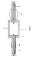
- FIG. 1 It consists of a tubular discharge vessel 2 made of ceramic, in which two electrodes are inserted (not visible).
- the discharge vessel has a central part 5 and two ends 4 at the ends sit two tailpipes 6, which are designed here as capillaries.
- the discharge vessel and the tailpipes are integrally made of a material such as PCA.
- the discharge vessel 2 is surrounded by an outer bulb 7, which terminates a base 8.
- the discharge vessel 2 is supported in the outer bulb by means of a rack including a short and long power supply 11a and 11b.
- a rack including a short and long power supply 11a and 11b.
- At the tail pipes 6 are each slats 10 which extend like a fins radially outward.
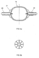
- FIG. 2 shows a plan view of the region of a tailpipe 6.
- the fins 10 have two broad sides 12 and a narrow side 13.
- the fins are distribuvilleig evenly distributed around the tailpipe.
- the fins have a maximum height of about half the maximum height of the central part of the discharge vessel.
- FIG. 3 shows a discharge vessel 2, wherein in the left-hand embodiment, the fins 15 branch off from approximately the maximum height of the end of the discharge vessel and maintain the height. In the right-hand embodiment, the mass of the blade is significantly lower by the maximum height of the blade with increasing distance from the end 4 decreases evenly.
- FIG. 4 shows on the left possibility to effect the cooling only by a coating 16 which completely surrounds the tailpipe 6 like a cuff in its middle part.
- a type of lamella 17 is shown, which is located only on the tailpipe 6 itself and does not extend further to the discharge vessel 2, which is here separate from the capillary.
- the lamella 17 is here shaped like a circle segment.
- FIG. 5 shows in the left embodiment, a discharge vessel 19 with a short tailpipe 20 and very short fins 21, but a total of eight fins are used.
- FIG. 5 further shows in the right embodiment of an arrangement in which these slats additionally a rotationally symmetric. Coating 22 is used after the fins.
- Further embodiments are those with a higher numbering than 8, in particular up to 16.
- the number of fins does not have to be even, it can also be odd, for example five fins.
- Another embodiment is characterized in that differently designed groups of lamellae are used, for example two groups on a tailpipe whose width and height are different and which alternate.
- Each fin or fin has a given maximum height that extends radially to the axis of the discharge vessel and a maximum length that extends axially and a maximum width. All three sizes can have a constant value, but they usually vary so that they are optimally adapted to the needs.
- the height H of the fin or lamella may vary from a fraction, in particular one tenth, of the difference DF between half the maximum outer diameter of the discharge vessel and the half diameter of the capillary up to twice, in particular 1.4 times, particularly preferably to the simple, this difference DF range. So 1/10 DF ⁇ H ⁇ 2 DF. Preferably, 1/5 DF ⁇ H ⁇ 1.4 DF.
- the fins may also be stepped, that is, their height H varies in steps along the length L.
- the width B of the fin is often constant and usually ranges from 0.2 to 1.5 mm.
- a second preferred embodiment is a radially outwardly decreasing width.
- an outwardly increasing width wherein in particular the arc length BL of the width B remains constant.
- a typical arc length BL is 1/10 of the circumference U of the tailpipe down to 1/50 U.
- Another shape of the width of the fin is triangular or in particular trapezoidal, seen in cross section.
- FIG. 7 shows a discharge vessel 25 with stepped blades 27, so that the height H of the blade changes abruptly.
- the definition of the total length GL is shown here.
- FIG. 8 shows a cylindrical discharge vessel 30 with stepped blades 26, in which the fins extend over the entire length of the tail pipe.
- a lower part 26a of the blades is pulled to the end of the discharge vessel, the height of the blades continues to increase in two stages.
- Part 26b has about 50% of the height corresponding to the diameter of the discharge vessel and part 26c has 100% of the height of the diameter of the discharge vessel.
- FIG. 9 shows a cylindrical discharge vessel 30, in which the entire length of the discharge vessel is coated with fins 35.
- FIG. 10 shows a representation of the end 36 of a discharge vessel, which is closed by a separate plug 37.
- the blade 38 here has the shape of a fin, which attaches just behind the line PL and then extends approximately to the approach of the tail pipe 39. Small fins 40 are additionally arranged on the plug 37.
- the term projection line PL at the tip of the electrode 41 is explained in this figure.
- the essence of the invention resides in that at least at one end of the discharge vessel there are fin-like fins, as shown here as 38, which extend radially outwards in their height H, the surface of the fins is arranged predominantly in a region which is located away from discharge behind a line which is determined by the projection of the tip of the electrode on the inner surface of the discharge vessel. Preferably, this proportion is at least two-thirds. But it can be up to 100%.
- the fin can only extend between the projection line PL and the projection AA of the tailpipe, where it exerts the highest effect, or extends further back to a part or the entire length of the tailpipe. But it can also be located only in the tailpipe.
- the dashed lines show possible embodiments of the fin.
- FIG. 11 shows a scheme for explaining the concepts of height H, width B and length L of the slats.
- variable size of the dimensions H, B and L in each case a maximum height, width or length is meant.
Description
Die Erfindung geht aus von einer Hochdruckentladungslampe gemäß dem Oberbegriff des Anspruchs 1. Derartige Lampen sind insbesondere Hochdruckentladungslampen mit keramischem Entladungsgefäß für die Allgemeinbeleuchtung. Es handelt sich insbesondere um Metallhalogenidlampen oder auch Natriumhochdrucklampen oder Quecksilberhochdrucklampen.The invention relates to a high-pressure discharge lamp according to the preamble of claim 1. Such lamps are in particular high-pressure discharge lamps with a ceramic discharge vessel for general lighting. These are, in particular, metal halide lamps or else sodium high-pressure lamps or high-pressure mercury lamps.
Die
Aus der
Die
Die Aufgabe der vorliegenden Erfindung ist es, eine Hochdruckentladungslampe bereitzustellen, deren Farbstreuung gegenüber bisherigen Lampen deutlich reduziert ist.The object of the present invention is to provide a high-pressure discharge lamp whose color spread is significantly reduced compared to previous lamps.
Diese Aufgabe wird gelöst durch die kennzeichnenden Merkmale des Anspruchs 1.This object is achieved by the characterizing features of claim 1.
Besonders vorteilhafte Ausgestaltungen finden sich in den abhängigen Ansprüchen.Particularly advantageous embodiments can be found in the dependent claims.
Die Hochdruckentladungslampe mit einem keramischen Entladungsgefäß besitzt einen zentralen Teil und zwei Enden, die durch Endrohre verschlossen sind, wobei Elektroden in den Endrohre verankert sind, die sich in das vom Entladungsgefäß umhüllte Entladungsvolumen erstrecken, wobei eine Füllung, die Metallhalogenide oder auch Metalle enthält, im Entladungsvolumen untergebracht ist. Dabei sitzen an den Enden flossenartige Lamellen, die sich radial nach außen erstrecken. Dabei ist die Oberfläche der Lamellen insgesamt überwiegend in einem Bereich angeordnet, der entladungsabgewandt hinter einer Linie liegt, die durch die Projektion der Spitze der Elektrode auf die innere Oberfläche des Entladungsgefäßes festgelegt wird Bevorzugt ist die Anordnung der Lamellen rotationssymmetrisch zueinander, insbesondere mit einer drei- bis achtzähligen Symmetrie. Dabei kann der Einfachheit halber die Form der Lamellen im wesentlichen gleichartig sein, muss es aber nicht. Es können beispielsweise zwei Sätze von Lamellen abwechselnd verwendet werden, für eine achtzählige Symmetrie also je vier einer Sorte.The high-pressure discharge lamp with a ceramic discharge vessel has a central part and two ends which are closed by tailpipes, wherein electrodes are anchored in the tailpipes, which extend into the discharge volume enveloped by the discharge vessel, wherein a filling containing metal halides or metals in the Discharge volume is housed. In this case, fin-like lamellae which extend radially outward are seated at the ends. It is the surface of the lamellae is generally arranged predominantly in a region which lies behind a line away from discharge, which is determined by the projection of the tip of the electrode onto the inner surface of the discharge vessel. The arrangement of the lamellae is preferably rotationally symmetrical to each other, in particular with a three- to eight-fold Symmetry. Here, for the sake of simplicity, the shape of the slats may be substantially similar, but need not. For example, two sets of lamellae may be alternately used, for an eightfold symmetry, four each of a kind.
Die Erfindung ist besonders geeignet für hochbelastete Metallhalogenidlampen, bei denen das Verhältnis zwischen der Innenlänge und dem maximalen Innendurchmesser des Entladungsgefäßes, das sog. Aspektverhältnis, zwischen 1,0 und 8,0, bevorzugt mindestens 1,5, liegt. Grenzwerte sind eingeschlossen.The invention is particularly suitable for highly loaded metal halide lamps in which the ratio between the inner length and the maximum inner diameter of the discharge vessel, the so-called aspect ratio, is between 1.0 and 8.0, preferably at least 1.5. Limits are included.
Fertigungstechnisch ist es vorteilhaft, dass die Breite der Lamellen in der Größenordnung der Wandstärke des zentralen Teils des Entladungsgefäßes liegt, und zwar im Falle konstanter Breite insbesondere höchstens 50 %, bevorzugt höchstens 25 %, von dieser Wandstärke abweicht.Manufacturing technology, it is advantageous that the width of the lamellae is of the order of the wall thickness of the central part of the discharge vessel, and in the case of constant width in particular at most 50%, preferably at most 25%, deviates from this wall thickness.
Insbesondere sind vorteilhaft die Endrohre als Kapillaren ausgeführt. Sie können aber auch anders ausgeführt sein, siehe beispielsweise
Besonders gute Kühlwirkung lässt sich erzielen, wenn die Lamellen auf einem Teil der Endrohre sitzen, der den Enden benachbart ist, oder wenn die Lamellen an den Enden ansetzen.Particularly good cooling effect can be achieved if the lamellae sit on a part of the tailpipes that is adjacent to the ends, or if the lamellae start at the ends.
Im allgemeinen haben die Lamellen zwei Breitseiten und eine Schmalseite, wobei die Schmalseite radial nach außen zeigt. Diese Seiten definieren zusammen die Oberfläche der Lamelle. Besonders bevorzugt kann die Schmalseite abgeschrägt sein und insbesondere mit einer Beschichtung versehen sein. Die Beschichtung sollte hochemissiv sein. Geeignete Materialien sind insbesondere Graphit oder Carbon, also andere Kohlenstoff-Modifikationen wie z.B. DLC (diamond-like carbon).In general, the lamellae have two broad sides and a narrow side, the narrow side pointing radially outward. These sides together define the surface of the lamella. Particularly preferably, the narrow side can be bevelled and in particular be provided with a coating. The coating should be highly viscous. Suitable materials are especially graphite or carbon, so other carbon modifications such as DLC (diamond-like carbon).
Generell kann das Kühlungsverhalten auch dadurch gesteuert werden, daß ein Teil des Endrohrs, insbesondere ein Teil der Lamelle wie die Schmalseite, mit einer Beschichtung hoher Emissivität bedeckt ist. Es ist auch möglich, eine Beschichtung auf dem Endrohr ohne gleichzeitige Benutzung eines lamellenartigen Vorsprungs an dieser Stelle zu verwenden.In general, the cooling behavior can also be controlled by covering a part of the tailpipe, in particular a part of the lamella like the narrow side, with a coating of high emissivity. It is also possible to use a coating on the tailpipe without simultaneous use of a lamellar projection at this point.
Als Material des Kolbens kann A1203, insbesondere PCA, oder jede andere übliche Keramik wie AlON oder AIN verwendet werden. Auch die Wahl der Füllung unterliegt keiner besonderen Einschränkung.As the material of the piston A1203, in particular PCA, or any other conventional ceramics such as AlON or AIN can be used. The choice of filling is subject to no particular restriction.
Entladungsgefäße oder Brenner für Hochdrucklampen mit annähernd gleichmäßiger Wanddickenverteilung und schlank auslaufenden Endenformen zeigen abhängig von der Füllungszusammensetzung teilweise hohe Farbstreuung durch starke Verteilung der Metallhalogenid-Füllung im Innern des Entladungsgefäßes. Typisch kondensiert die Füllung in dem entladungsfernen Bereich hinter der Linie, die durch Projektion der Elektrodenspitze auf die innere Brenner-Oberfläche festgelegt wird. Die Füllungspositionierung auf eine Zone der Oberfläche im Innern des Entladungsgefäßes, die einem engen Temperaturbereich entspricht, und in die Restvolumina der -eventuell vorhandenen- Kapillaren hinein ist bisher nicht ausreichend genau einstellbar. Deshalb kommt es jetzt darauf an, Finnen oder Lamellen an das Entladungsgefäß anzusetzen, deren Wirkung überwiegend in einem Bereich zum Tragen kommt, der hinter der Linie liegt, die durch Projektion der Elektrodenspitze auf die innere Brenner-Oberfläche festgelegt wird. Überwiegend bedeutet insbesondere, dass mindestens zwei Drittel der Oberfläche der Finnen in einem Bereich aufgespannt ist, der entladungsfern hinter der Linie liegt, die durch Projektion der Elektrodenspitze auf die Wand des Entladungsgefäßes festgelegt wird.Depending on the filling composition, discharge vessels or burners for high-pressure lamps with approximately uniform wall thickness distribution and slim-running end shapes exhibit, in some cases, high color scattering due to the strong distribution of the metal halide filling in the interior of the discharge vessel. Typically, the charge in the discharge-away region condenses behind the line defined by projection of the electrode tip onto the inner burner surface. The filling position on a zone of the surface in the interior of the discharge vessel, which corresponds to a narrow temperature range, and in the residual volumes of -eventuell-existing capillaries into is not sufficiently accurately adjustable. Therefore, it is now important to apply fins or lamellae to the discharge vessel, the effect of which predominantly occurs in an area which lies behind the line which is determined by projecting the electrode tip onto the inner burner surface. In particular, predominantly means that at least two-thirds of the surface of the fins is mounted in an area which is behind the line away from discharge, which is determined by projection of the electrode tip on the wall of the discharge vessel.
Bisherige Entladungsgefäße haben oft eine Form mit verstärkter Wanddicke an den Endflächen, z.B. bei zylindrischen Brennerformen, und erzeugen dadurch eine vergrößerte Endenoberfläche. Ein weiteres Problem ist die durch den wanddickenabhängigen spezifischen Emissionskoeffizienten der Keramik erhöhte Abstrahlung von IR-Strahlung beim Betrieb des Entladungsgefäßes im evakuierten oder gasgefüllten Außenkolben. Dabei wird die Oberfläche des Entladungsgefäßes durch die spezifische Abstrahlungsleistung nach dem Stefan-Boltzmann-Gesetz bestimmt: ![]()
![]()
Dabei ist
Prad / A: abgestrahlte Strahlungsleistung pro Oberflächeneinheit;
ε = hemisphärischer Emissionskoeffizient der abstrahlenden Oberfläche,
σ = Stefan-Boltzmann-Konstante,
T = Oberflächentemperatur.It is
P rad / A: radiated radiant power per unit surface area;
ε = hemispherical emission coefficient of the radiating surface,
σ = Stefan Boltzmann constant,
T = surface temperature.
Hierdurch wird durch einen Wärmesenkeneffekt am Ende des Entladungsgefäßes eine konzentrierte Füllungsverteilung erzeugt , die die Dampfdrücke der verwendeten Metallhalogenide im Entladungsgefäß derart bestimmt, dass ein für Keramiklampensysteme ausreichender Farbstreuungswert von typisch ≤ 75 K für größere Lampengruppen gleicher Betriebsleistung einstellbar ist.In this way, a concentrated charge distribution is generated by a heat sink effect at the end of the discharge vessel, which determines the vapor pressures of the metal halides used in the discharge vessel such that a sufficient for ceramic lamp systems color scattering value of typically ≤ 75 K for larger lamp groups the same operating performance is adjustable.
Bei kugeligen Entladungsgefäßen, oder solchen mit Halbkugelendformen oder konisch zulaufenden Endenformen oder elliptisch ausformten Endenformen und zylindrischem Mittenteil relativ hoher Aspektverhältnisse IL/ID von etwa 1,5 bis 8 ergeben sich besonders gravierende Probleme. Aufgrund des schlanken Übergangs in den Bereich des Endrohrs, meist ein Kapillarbereich, ergeben sich teilweise unzureichende Kühlungseffekte am Ende des Entladungsgefäßes und damit eine unzureichende Festlegung der Temperatur, die für eine konzentrierte Füllungsablagerung in einem engen Temperaturbereich der Innenwandung nicht ausreicht.In spherical discharge vessels, or those with Halbkugelendformen or tapered end shapes or elliptical shaped end shapes and cylindrical center portion relatively high aspect ratios IL / ID of about 1.5 to 8, particularly serious problems arise. Due to the slim transition into the region of the tailpipe, usually a capillary area, partially insufficient cooling effects at the end of the discharge vessel and thus an insufficient determination of the temperature, which is not sufficient for a concentrated charge deposit in a narrow temperature range of the inner wall.
Erfindungsgemäß sind im wesentlichen zwei Mechanismen zur verstärkten Kühlung des Endes des Entladungsgefäßes vorgesehen. Damit ist der Übergang des Entladungsgefäßes, in dem die Bogenentladung brennt, zu den Endenformen gemeint, die die Elektrodenstrukturen zur elektrischen bzw. elektromagnetischen Leitungseinkopplung enthalten. Dies gilt insbesondere, falls keine deutliche Vergrößerung der Wanddicke im Endenbereich gegenüber der Wanddicke des Entladungsgefäßes --bei zylindrischen Entladungsgefäßen handelt es sich typisch um einen Faktor 1,5 bis 2,5-- durch die Formgebung vorgegeben wird. Eine Anwendung dafür ist jedoch nicht ausgeschlossen.According to the invention, essentially two mechanisms for intensified cooling of the end of the discharge vessel are provided. Thus, the transition of the discharge vessel in which the arc discharge burns is meant to the end forms containing the electrode structures for electrical or electromagnetic line coupling. This applies in particular, if no significant increase in the wall thickness in the end region relative to the wall thickness of the discharge vessel - in cylindrical discharge vessels are typically around a factor of 1.5 to 2.5-- is given by the shaping. However, an application for this is not excluded.
Wesentlich ist die Vergrößerung der Oberfläche durch im Übergangsbereich an das Endrohr angeformte flügel- bzw. flossenartige Ausformungen, bevorzugt mit longitudinaler Ausrichtung parallel zur Achse mit mindestens dreizähliger Symmetrie und maximal achtzähliger Symmetrie der Verteilung um dem Umfang. Insbesondere handelt es sich um Lamellen.Essential is the enlargement of the surface by integrally formed in the transition region to the tail pipe wing-like or fin-like formations, preferably with longitudinal alignment parallel to the axis with at least threefold symmetry and a maximum achtzähliger symmetry of the distribution around the circumference. In particular, they are slats.
Die flossenartigen Ausformungsbereiche können im wesentliche glatte Flächen sein oder auch oberflächlich facettiert ausgebildet sein. insbesondere können die Facettenbereiche zum übrigen Oberflächenbereich der Lamelle flächig abgegrenzt sein und zur Achse und zum Schwerpunkt des Entladungsgefäßes eine definierte Ausrichtung aufweisen.The fin-like molding areas may be substantially smooth surfaces or be formed on the surface faceted. In particular, the facet regions can be delimited over the entire surface area of the lamella and have a defined orientation relative to the axis and to the center of gravity of the discharge vessel.
Hinzu kommt u.U eine Beschichtung mit einem Material, das im Nahen Infrarot (NIR), womit typisch ein Wellenlängenbereich zwischen 1 und 3 µm gemeint ist, gegenüber dem Keramik-Material eine erhöhte hemisphärische Emissivität ε im Temperaturbereich zwischen 650 und 1000°C aufweist. Die Beschichtung sollte vorzugsweise im Bereich des Überganges zwischen Ende des Entladungsgefäßes und Endrohr angebracht sein. Insbesondere gilt dies für das Endrohr auch alleine, wo die Beschichtung auch ohne Lamelle aufgebracht sein kann.In addition u.U comes a coating with a material that in the near infrared (NIR), which is typically a wavelength range between 1 and 3 microns, compared to the ceramic material has an increased hemispherical emissivity ε in the temperature range between 650 and 1000 ° C. The coating should preferably be applied in the region of the transition between the end of the discharge vessel and tailpipe. In particular, this also applies to the tailpipe alone, where the coating can be applied without a lamella.
Als Beschichtungsmaterialien eignen sich hochtemperaturfeste Beschichtungen mit hemisphärischen Emissionskoeffizienten ε bevorzugt ε ≥ 0.6. darunter fällt Graphit, Mischungen von Al2O3 mit Graphit, Mischungen von Al2O3 mit Carbiden der Metalle Ti, Ta, Hf, Zr, sowie von Halbmetallen wie Si. Geeignet sich auch Mischungen, die noch zusätzlich andere Metalle zur Einstellung eventuell gewünschter elektrischer Leitfähigkeit enthalten.High-temperature-resistant coatings with hemispherical emission coefficients ε, preferably ε ≥ 0.6, are suitable as coating materials. Among them is graphite, mixtures of Al2O3 with graphite, mixtures of Al2O3 with carbides of the metals Ti, Ta, Hf, Zr, as well as of semi-metals such as Si. Also suitable are mixtures which additionally contain other metals for adjusting any desired electrical conductivity.
Selbstverständlich können beide Maßnahmen miteinander geeignet kombiniert werden, so dass ein Teil der Oberflächenabstrahlungserhöhung über eine Vergrößerung der Oberfläche durch Lamellen und gleichzeitig ein Teil durch die Beschichtung von Teilen dieser Lamellen oder der angrenzenden kälteren Endrohrsbereiche erfolgt.Of course, both measures can be suitably combined with each other, so that part of the surface radiation increase takes place via an enlargement of the surface by fins and at the same time a part by the coating of parts of these fins or the adjacent colder tailpipe areas.
Insgesamt ergeben sich eine Reihe von Vorteilen bei Verwendung integraler Lamellen bei keramischen Entladungsgefäßen:
- 1. Effektivere Kühlung bei gleichzeitig relativ geringer zusätzlicher Keramikmasse;
- 2. Verringerung des longitudinalen Wärmeflusses in die Endrohr;
- 3. deutlich vergrößerte Flexibilität der Oberflächeneinstellung im Endenbereich;
- 4. Verringerung der Abschattungseffekte im Raumwinkelbereich der Elektrodenzuführung;
- 5. Einstellbarkeit effektiver lokaler Thermostatwirkung mittels relativ kleiner Oberflächenbereiche.
- 1. More effective cooling with relatively low additional ceramic mass;
- 2. Reduction of the longitudinal heat flow into the tailpipe;
- 3. significantly increased flexibility of the surface adjustment in the end region;
- 4. reduction of shading effects in the solid angle range of the electrode feed;
- 5. Adjustability of effective local thermostatic effect by means of relatively small surface areas.
Diese Eigenschaften sind insbesondere für hochbelastete Formen von Entladungsgefäßen mit kleiner Gesamtoberfläche und evtl. erhöhtem Aspektverhältnis wichtig, da unter diesen Voraussetzungen eine lokale Kühlung durch Wärmefluss über relativ große Wandquerschnittsflächen schwierig wird.These properties are particularly important for highly loaded forms of discharge vessels with a small total surface area and possibly increased aspect ratio, since under these conditions a local cooling by heat flow over relatively large wall cross-sectional areas becomes difficult.
Die Gesamtmasse des Entladungsgefäßes erhöht sich durch diese art von Lamellen nur unwesentlich und bleibt damit unter einem kritischen Wert, der das Anlaufverhalten der Lampe bei der Zündung negativ beeinflussen würde. Es gibt somit einen ausgeklügelten Kompromiss zwischen guter Zündung und effektiver Kühlung. Diese Maßnahme erlaubt eine sehr hohe Farbstabilität unter der bewussten Inkaufnahme einer schlechten Isothermie. Dies geschieht in Abkehr von der bisherigen Zielsetzung möglichst guter Isothermie und erlaubt es die Zone der Kondensation der Füllung exakt zu bestimmen durch bewusste Gestaltung eines Temperaturgradienten.The total mass of the discharge vessel increases only insignificantly by this type of fins and thus remains below a critical value that would adversely affect the start-up behavior of the lamp when ignited. There is thus a sophisticated compromise between good ignition and effective cooling. This measure allows a very high color stability under the conscious acceptance of a bad isotherm. This is done in departure from the previous objective of the best possible isotherm and allows the zone of condensation of the filling to be determined exactly by deliberately designing a temperature gradient.
Bei völligem Verzicht auf eine Beschichtung ist der Bereich der Lamellen optisch transparent bzw. zumindest transluzent. Dies sollte möglichst auch für Bereiche mit Beschichtung angestrebt werden. um dieses ziel anzunähern wird der Raumwinkel, unter dem die Bereiche mit Beschichtung vom Zentrum der Lampe aus erscheinen, möglichst minimiert. Denn die Beschichtung absorbiert Strahlung und kostet daher Effizienz. Aus diesem Grund soll die Beschichtung auf schräg geneigte Flächen der Lamellen aufgebracht werden, da dann vom Zentrum aus deren Raumwinkel kleiner erscheint. Insbesondere gilt dies für die Schmalseite der Lamellen. Eine Alternative ist, die Beschichtung möglichst weit hinten auf der Lamelle und/oder der Endrohr anzubringen, da auch dadurch der effektiv abgeschattete Raumwinkel verkleinert wird. auf diese Weise kann ein optimaler Wert der Kühlung bei gleichzeitig optimaler Effizienz erzielt werden. Besonders effektive Beschichtungen sind Graphit und TiC.In the complete absence of a coating, the area of the lamellae is optically transparent or at least translucent. If possible, this should also be the goal for areas with coating. To approximate this goal, the solid angle below which the areas of coating appear from the center of the lamp is minimized as much as possible. Because the coating absorbs radiation and therefore costs efficiency. For this reason, the coating should be applied to inclined surfaces of the slats, since then from the center of their solid angle smaller appears. This applies in particular to the narrow side of the slats. An alternative is to place the coating as far back as possible on the lamella and / or the tailpipe, since this also reduces the effectively shaded solid angle. In this way, an optimal value of the cooling can be achieved while maintaining optimum efficiency. Particularly effective coatings are graphite and TiC.
Ein Steuerungsmittel der Kühlwirkung ist auch die maximale Höhe der Lamelle, insbesondere wenn sie am Entladungsgefäß ansetzt, da je nach Ansatzhöhe die Ableitung von einem anderen Temperatur-Niveau aus erfolgt.A control means of the cooling effect is also the maximum height of the blade, especially if it attaches to the discharge vessel, since depending on the approach height, the discharge takes place from a different temperature level.
Ein besonderer Vorteil derartiger integraler Lamellen ist, dass sie zum einen besonders effektiv kühlen, verglichen mit separaten Aufsätzen, und daß sie einfach herzustellen sind, wenn man moderne Fertigungsverfahren wie Spritzguss-, Schlickerguss oder rapid prototyping-Verfahren verwendet.A particular advantage of such integral lamellae is that they are particularly effective at cooling compared to separate lids, and that they are easy to manufacture using modern manufacturing techniques such as injection molding, slip casting or rapid prototyping.
Im Folgenden soll die Erfindung anhand mehrerer Ausführungsbeispiele näher erläutert werden. Die Figuren zeigen:
- Fig. 1
- eine Hochdruckentladungslampe;
- Fig. 2
- ein detail der Entladungslampe aus
Figur 1 ; - Fig. 3, 5a, 5b, 10
- Ausführungsbeispiele eines Entladungsgefäßes;
- Fig. 4, 6-9
- weitere Entladungsgefäße;
- Figur 11
- eine schematische Darstellung der geometrischen Parameter der Lamellen;
- Fig. 1
- a high pressure discharge lamp;
- Fig. 2
- a detail of the discharge lamp
FIG. 1 ; - Fig. 3, 5a, 5b, 10th
- Embodiments of a discharge vessel;
- Fig. 4, 6-9
- further discharge vessels;
- FIG. 11
- a schematic representation of the geometric parameters of the slats;
Das Entladungsgefäß 2 ist von einem Außenkolben 7 umgeben, den ein Sockel 8 abschließt. Das Entladungsgefäß 2 ist im Außenkolben mittels eines Gestells, das eine kurze und lange Stromzuführung 11a und 11b beinhaltet, gehaltert. An den Endrohre 6 sitzen jeweils Lamellen 10, die flossenartig sich radial nach außen erstrecken.The
Weitere Ausführungsbeispiele sind solche mit höherer Zähligkeit als 8, vornehmlich bis zu 16. Dabei muss die Anzahl der Finnen nicht geradzahlig sein, sie kann auch ungeradzahlig sein, beispielsweise fünf Finnen. Ein weiteres Ausführungsbeispiel zeichnet sich dadurch aus, dass unterschiedlich gestaltete Gruppen von Lamellen verwendet werden, beispielsweise zwei Gruppen an einer Endrohr, deren Breite und Höhe verschieden ist und die abwechseln.Further embodiments are those with a higher numbering than 8, in particular up to 16. The number of fins does not have to be even, it can also be odd, for example five fins. Another embodiment is characterized in that differently designed groups of lamellae are used, for example two groups on a tailpipe whose width and height are different and which alternate.
Jede Lamelle oder Finne besitzt eine gegebene maximale Höhe, die sich radial zur Achse des Entladungsgefäßes erstreckt, und eine maximale Länge, die sich axial erstreckt, sowie eine maximale Breite. Alle drei Größen können einen konstanten Wert besitzen, meist variieren sie jedoch so, dass sie den Bedürfnissen optimal angepasst sind.Each fin or fin has a given maximum height that extends radially to the axis of the discharge vessel and a maximum length that extends axially and a maximum width. All three sizes can have a constant value, but they usually vary so that they are optimally adapted to the needs.
Die Länge L der Finne oder Lamelle kann von einem Bruchteil der Gesamtlänge GL des Entladungsgefäßes einschließlich der Länge der Endrohre selbst, insbesondere von mindestens einem Zwanzigstel, bis zur halben Gesamtlänge reichen. Also gilt 1/20 GL ≤ L ≤ 0,5 GL. Im Falle, dass gilt L = 0,5 GL, erstreckt sich dann die Finne und ihr Gegenstück am anderen Ende zusammen effektiv über das gesamte Entladungsgefäß.The length L of the fin or lamella can range from a fraction of the total length GL of the discharge vessel including the length of the tailpipes themselves, in particular of at least one twentieth, to half the total length. So 1/20 GL ≤ L ≤ 0.5 GL. In the case where L = 0.5 GL, then the fin and its counterpart at the other end together effectively extend over the entire discharge vessel.
Die Höhe H der Finne oder Lamelle kann von einem Bruchteil, insbesondere einem Zehntel, der Differenz DF zwischen dem halben maximalen Außendurchmesser des Entladungsgefäßes und dem halben Durchmesser der Kapillare bis zum Doppelten, insbesondere dem 1,4-fachen, besonders bevorzugt bis zum Einfachen, dieser Differenz DF reichen. Also gilt 1/10 DF ≤ H ≤ 2 DF. Bevorzugt gilt 1/5 DF ≤ H ≤ 1,4 DF. Die Finnen können auch gestuft sein, das heißt, dass ihre Höhe H entlang der Länge L in Schritten variiert.The height H of the fin or lamella may vary from a fraction, in particular one tenth, of the difference DF between half the maximum outer diameter of the discharge vessel and the half diameter of the capillary up to twice, in particular 1.4 times, particularly preferably to the simple, this difference DF range. So 1/10 DF ≤ H ≤ 2 DF. Preferably, 1/5 DF ≦ H ≦ 1.4 DF. The fins may also be stepped, that is, their height H varies in steps along the length L.
Die Breite B der Finne ist häufig konstant und bewegt sich meist im Bereich 0,2 bis 1,5 mm. Eine zweite bevorzugte Ausführungsform ist eine radial nach außen abnehmende Breite. Möglich ist auch eine nach außen zunehmende Breite, wobei insbesondere die Bogenlänge BL der Breite B konstant bleibt. Eine typische Bogenlänge BL ist 1/10 des Umfangs U der Endrohr bis herab zu 1/50 U. Also gilt hier 1/50 ≤ BL/U ≤ 1/10. Eine andere Form der Breite der Finne ist dreieckig oder insbesondere trapezförmig, im Querschnitt gesehen.The width B of the fin is often constant and usually ranges from 0.2 to 1.5 mm. A second preferred embodiment is a radially outwardly decreasing width. Also possible is an outwardly increasing width, wherein in particular the arc length BL of the width B remains constant. A typical arc length BL is 1/10 of the circumference U of the tailpipe down to 1/50 U. Thus, 1/50 ≦ BL / U ≦ 1/10. Another shape of the width of the fin is triangular or in particular trapezoidal, seen in cross section.
Je länger die Finnen sind, desto geringer kann die Wandstärke des Entladungsgefäßes oder auch der Kapillare gewählt werden. Wenn die Finnen über die gesamte axiale Länge der Endrohr, meist eine Kapillare, gezogen werden, wird dadurch die Oberfläche der Endrohr stark vergrößert. Vergleicht man ein unstrukturiertes Rohr als Endrohr mit einem mit Finnen versehnen Rohr gleichen Außendurchmessers, so wird der Wärmefluss zu den Enden hin durch den verringerten Querschnitt reduziert.The longer the fins, the lower the wall thickness of the discharge vessel or the capillary can be selected. If the fins are pulled over the entire axial length of the tailpipe, usually a capillary, this greatly increases the surface area of the tailpipe. Comparing an unstructured tube as the tailpipe with a finned tube of the same outside diameter, the heat flow to the ends is reduced by the reduced cross-section.
Zugleich ist an dieser Figur der Begriff Projektionslinie PL an der Spitze der Elektrode 41 erläutert. Das Wesen der Erfindung liegt darin, dass mindestens auf einem Ende des Entladungsgefäßes flossenartige Lamellen wie hier als 38 gezeigt sitzen, die sich in ihrer Höhe H radial nach außen erstrecken, wobei die Oberfläche der Lamellen insgesamt überwiegend in einem Bereich angeordnet ist, der entladungsabgewandt hinter einer Linie liegt, die durch die Projektion der Spitze der Elektrode auf die innere Oberfläche des Entladungsgefäßes festgelegt wird. Bevorzugt ist dieser Anteil mindestens zwei Drittel. Er kann aber bis zu 100 % betragen. Die Finne kann sich dabei nur zwischen der Projektionslinie PL und dem Ansatz AA der Endrohr erstrecken, wo sie die höchste Wirkung entfaltet, oder sich noch weiter nach hinten auf einen Teil oder die gesamte Länge der Endrohr erstrecken. Sie kann aber auch nur im Bereich der Endrohr angesiedelt sein. Die gestrichelten Linien zeigen mögliche Ausführungsbeispiele der Flosse.At the same time, the term projection line PL at the tip of the
Claims (10)
- High-pressure discharge lamp (1) having a ceramic discharge vessel (2) with a central part (5) and two ends (4), on which two end tubes (6; 39) are positioned, electrodes being anchored in the end tubes and extending into the discharge volume enveloped by the discharge vessel, a filling, which contains metals and/or metal halides, being accommodated in the discharge volume, fin-like laminates (15) being positioned at least on one end (4) and extending radially outwards at their height H, the surface of the laminates being arranged in a region which is positioned, remote from the discharge, behind a plane which runs through the tip of the electrode and perpendicularly to a longitudinal axis of the lamp, and characterized in that the laminates (15) and the discharge vessel (2) are produced integrally from Al2O3, AlON or AlN.
- High-pressure discharge lamp according to Claim 1, characterized in that the arrangement of the laminates (15) is such that they are rotationally symmetrical to one another, in particular with a three-fold to eight-fold symmetry.
- High-pressure discharge lamp according to Claim 2, characterized in that the form of the laminates (15) is substantially identical or is identical in groups.
- High-pressure discharge lamp according to Claim 1, characterized in that the wall thickness of the laminates (15) approximately corresponds to the wall thickness of the central part (5) of the discharge vessel, to be precise in particular deviates from this by at most 50%.
- High-pressure discharge lamp according to Claim 1, characterized in that the end tubes are in the form of capillaries (6).
- High-pressure discharge lamp according to Claim 1, characterized in that the laminates have two broad sides and one narrow side, the narrow side being positioned radially on the outside.
- High-pressure discharge lamp according to Claim 6, characterized in that the narrow side is beveled and in particular is provided with a coating.
- High-pressure discharge lamp according to Claim 1, characterized in that part of the end tube, in particular part of the laminate, is covered with a coating having a high emissivity.
- High-pressure discharge lamp according to Claim 6, characterized in that at least one laminate has subareas of different heights H which are delimited by at least one edge, and at least one of these subareas is provided with a coating.
- High-pressure discharge lamp according to Claim 1, characterized in that the discharge vessel has a bulging shape, with the result that the diameter of the discharge vessel reduces in size towards the ends.
Applications Claiming Priority (2)
| Application Number | Priority Date | Filing Date | Title |
|---|---|---|---|
| DE102006002261A DE102006002261A1 (en) | 2006-01-17 | 2006-01-17 | High pressure discharge lamp |
| PCT/EP2007/050390 WO2007082885A1 (en) | 2006-01-17 | 2007-01-16 | High-pressure discharge lamp having cooling laminates fitted at the end of the discharge vessel |
Publications (2)
| Publication Number | Publication Date |
|---|---|
| EP1974367A1 EP1974367A1 (en) | 2008-10-01 |
| EP1974367B1 true EP1974367B1 (en) | 2010-07-14 |
Family
ID=37836793
Family Applications (1)
| Application Number | Title | Priority Date | Filing Date |
|---|---|---|---|
| EP07703905A Expired - Fee Related EP1974367B1 (en) | 2006-01-17 | 2007-01-16 | High-pressure discharge lamp having cooling laminates fitted at the end of the discharge vessel |
Country Status (7)
| Country | Link |
|---|---|
| US (1) | US7977884B2 (en) |
| EP (1) | EP1974367B1 (en) |
| JP (1) | JP4934152B2 (en) |
| CN (1) | CN101371329B (en) |
| CA (1) | CA2636354A1 (en) |
| DE (2) | DE102006002261A1 (en) |
| WO (1) | WO2007082885A1 (en) |
Families Citing this family (7)
| Publication number | Priority date | Publication date | Assignee | Title |
|---|---|---|---|---|
| US7728495B2 (en) * | 2007-08-01 | 2010-06-01 | Osram Sylvania Inc. | HID lamp with frit seal thermal control |
| DE102007045079A1 (en) * | 2007-09-21 | 2009-04-02 | Osram Gesellschaft mit beschränkter Haftung | High pressure discharge lamp |
| CN101828248B (en) * | 2007-10-19 | 2012-02-22 | 奥斯兰姆有限公司 | High-pressure discharge lamp |
| DE102008026522A1 (en) | 2008-06-03 | 2009-12-10 | Osram Gesellschaft mit beschränkter Haftung | High pressure discharge lamp |
| DE102009021524B3 (en) * | 2009-05-15 | 2010-11-11 | Osram Gesellschaft mit beschränkter Haftung | High pressure discharge lamp with cooling element |
| DE102009029867A1 (en) * | 2009-06-22 | 2010-12-23 | Osram Gesellschaft mit beschränkter Haftung | High pressure discharge lamp |
| US9552976B2 (en) | 2013-05-10 | 2017-01-24 | General Electric Company | Optimized HID arc tube geometry |
Citations (2)
| Publication number | Priority date | Publication date | Assignee | Title |
|---|---|---|---|---|
| EP1339090A1 (en) * | 2002-02-15 | 2003-08-27 | Harison Toshiba Lighting Corporation | Metal halide lamp and automotive headlamp apparatus |
| US20050153837A1 (en) * | 1995-11-08 | 2005-07-14 | Towa Chemical Industry Co., Ltd. | Raney catalyst, process for producing it and process for producing a sugar-alcohol using the same |
Family Cites Families (15)
| Publication number | Priority date | Publication date | Assignee | Title |
|---|---|---|---|---|
| US4970431A (en) * | 1987-11-03 | 1990-11-13 | U.S. Philips Corporation | High-pressure sodium discharge lamp with fins radially extending from the discharge vessel for controlling the wall temperature of the discharge vessel |
| US4983889A (en) * | 1989-05-15 | 1991-01-08 | General Electric Company | Discharge lamp using acoustic resonant oscillations to ensure high efficiency |
| JPH034436A (en) | 1989-05-31 | 1991-01-10 | Iwasaki Electric Co Ltd | Metal halide lamp and lighting device therefor |
| EP0506182B1 (en) | 1991-03-28 | 1996-09-11 | Koninklijke Philips Electronics N.V. | High pressure gas discharge lamps |
| KR100268722B1 (en) * | 1993-08-21 | 2000-10-16 | 김순택 | High pressure discharge light |
| JPH08250071A (en) | 1995-03-14 | 1996-09-27 | Ushio Inc | Lamp and light source device |
| US5825129A (en) * | 1996-05-31 | 1998-10-20 | U.S. Philips Corporation | High pressure discharge lamp having pirch seals |
| JPH1092385A (en) * | 1996-09-12 | 1998-04-10 | Matsushita Electron Corp | Bulb |
| DE19727429A1 (en) | 1997-06-27 | 1999-01-07 | Patent Treuhand Ges Fuer Elektrische Gluehlampen Mbh | Metal halide lamp with ceramic discharge tube |
| JP2002151005A (en) * | 2000-11-14 | 2002-05-24 | Ushio Inc | Discharge lamp |
| US6566814B2 (en) | 2001-04-24 | 2003-05-20 | Osram Sylvania Inc. | Induction sealed high pressure lamp bulb |
| US7233109B2 (en) * | 2002-01-16 | 2007-06-19 | Koninklijke Philips Electronics, N.V. | Gas discharge lamp |
| JP4048135B2 (en) * | 2002-02-25 | 2008-02-13 | 松下電器産業株式会社 | Metal halide lamp |
| JP2004362929A (en) * | 2003-06-04 | 2004-12-24 | Ceramission Kk | Discharge lamp |
| US7394200B2 (en) * | 2005-11-30 | 2008-07-01 | General Electric Company | Ceramic automotive high intensity discharge lamp |
-
2006
- 2006-01-17 DE DE102006002261A patent/DE102006002261A1/en not_active Withdrawn
-
2007
- 2007-01-16 CN CN2007800024911A patent/CN101371329B/en not_active Expired - Fee Related
- 2007-01-16 US US12/087,470 patent/US7977884B2/en not_active Expired - Fee Related
- 2007-01-16 CA CA002636354A patent/CA2636354A1/en not_active Abandoned
- 2007-01-16 JP JP2008550745A patent/JP4934152B2/en not_active Expired - Fee Related
- 2007-01-16 EP EP07703905A patent/EP1974367B1/en not_active Expired - Fee Related
- 2007-01-16 DE DE502007004388T patent/DE502007004388D1/en active Active
- 2007-01-16 WO PCT/EP2007/050390 patent/WO2007082885A1/en active Application Filing
Patent Citations (2)
| Publication number | Priority date | Publication date | Assignee | Title |
|---|---|---|---|---|
| US20050153837A1 (en) * | 1995-11-08 | 2005-07-14 | Towa Chemical Industry Co., Ltd. | Raney catalyst, process for producing it and process for producing a sugar-alcohol using the same |
| EP1339090A1 (en) * | 2002-02-15 | 2003-08-27 | Harison Toshiba Lighting Corporation | Metal halide lamp and automotive headlamp apparatus |
Also Published As
| Publication number | Publication date |
|---|---|
| DE502007004388D1 (en) | 2010-08-26 |
| JP4934152B2 (en) | 2012-05-16 |
| JP2009524185A (en) | 2009-06-25 |
| CN101371329B (en) | 2010-11-10 |
| CN101371329A (en) | 2009-02-18 |
| CA2636354A1 (en) | 2007-07-26 |
| US7977884B2 (en) | 2011-07-12 |
| WO2007082885A1 (en) | 2007-07-26 |
| US20080315770A1 (en) | 2008-12-25 |
| EP1974367A1 (en) | 2008-10-01 |
| DE102006002261A1 (en) | 2007-07-19 |
Similar Documents
| Publication | Publication Date | Title |
|---|---|---|
| EP1974367B1 (en) | High-pressure discharge lamp having cooling laminates fitted at the end of the discharge vessel | |
| EP0451647B1 (en) | High-pressure discharge lamp and method for its manufacture | |
| EP0703600B1 (en) | High pressure discharge lamp | |
| DE19645960A1 (en) | Ceramic discharge tube | |
| DE2623099A1 (en) | SHORT ARC DISCHARGE LAMP | |
| EP0839381B1 (en) | Reflector lamp | |
| DE60033728T2 (en) | High pressure discharge lamp | |
| DE112010001690T5 (en) | Ceramic metal halide lamp | |
| WO2010145739A1 (en) | Lamp unit | |
| EP2201596B1 (en) | High-pressure discharge lamp | |
| EP2394291A1 (en) | High-pressure discharge lamp | |
| EP2342737B1 (en) | Halogen incandescent lamp for operation on mains voltage | |
| DE69825035T2 (en) | High-pressure discharge lamp | |
| DE3033182A1 (en) | Filament for an incandescent lamp | |
| DE102005029260A1 (en) | Gluhhreflektorwärmampe with uniform irradiance | |
| EP0989587A1 (en) | High pressure discharge lamp and associated luminaire | |
| DE102018206770A1 (en) | Electrode for a discharge lamp, discharge lamp and method for producing an electrode | |
| DE102018207038A1 (en) | ELECTRODE FOR A DISCHARGE LAMP, DISCHARGE LAMP AND METHOD FOR PRODUCING AN ELECTRODE | |
| EP2281298B1 (en) | High-pressure discharge lamp | |
| WO2008049766A2 (en) | Reflector lamp | |
| DE102005008140A1 (en) | High pressure discharge lamp as for motor vehicle headlights with less than fifty watt power consumption has narrow transparent ceramic tube of uniform bore with two electrodes and xenon and metal halide filling | |
| DE102012209078B4 (en) | Flash lamp with prismatic lamp body | |
| EP1482534B1 (en) | Lighting device comprising a gas discharge lamp and a protective sleeve | |
| DE60224041T2 (en) | FLUORESCENT LAMP AND METHOD OF MANUFACTURING | |
| DE19653364C2 (en) | flash tube |
Legal Events
| Date | Code | Title | Description |
|---|---|---|---|
| PUAI | Public reference made under article 153(3) epc to a published international application that has entered the european phase |
Free format text: ORIGINAL CODE: 0009012 |
|
| 17P | Request for examination filed |
Effective date: 20080613 |
|
| AK | Designated contracting states |
Kind code of ref document: A1 Designated state(s): DE FR GB NL |
|
| 17Q | First examination report despatched |
Effective date: 20081024 |
|
| RBV | Designated contracting states (corrected) |
Designated state(s): DE FR GB NL |
|
| GRAP | Despatch of communication of intention to grant a patent |
Free format text: ORIGINAL CODE: EPIDOSNIGR1 |
|
| DAX | Request for extension of the european patent (deleted) | ||
| RAP1 | Party data changed (applicant data changed or rights of an application transferred) |
Owner name: OSRAM GESELLSCHAFT MIT BESCHRAENKTER HAFTUNG |
|
| GRAS | Grant fee paid |
Free format text: ORIGINAL CODE: EPIDOSNIGR3 |
|
| GRAA | (expected) grant |
Free format text: ORIGINAL CODE: 0009210 |
|
| AK | Designated contracting states |
Kind code of ref document: B1 Designated state(s): DE FR GB NL |
|
| REG | Reference to a national code |
Ref country code: GB Ref legal event code: FG4D Free format text: NOT ENGLISH |
|
| REF | Corresponds to: |
Ref document number: 502007004388 Country of ref document: DE Date of ref document: 20100826 Kind code of ref document: P |
|
| REG | Reference to a national code |
Ref country code: NL Ref legal event code: T3 |
|
| PLBE | No opposition filed within time limit |
Free format text: ORIGINAL CODE: 0009261 |
|
| STAA | Information on the status of an ep patent application or granted ep patent |
Free format text: STATUS: NO OPPOSITION FILED WITHIN TIME LIMIT |
|
| PGFP | Annual fee paid to national office [announced via postgrant information from national office to epo] |
Ref country code: FR Payment date: 20110120 Year of fee payment: 5 |
|
| 26N | No opposition filed |
Effective date: 20110415 |
|
| REG | Reference to a national code |
Ref country code: DE Ref legal event code: R097 Ref document number: 502007004388 Country of ref document: DE Effective date: 20110415 |
|
| PGFP | Annual fee paid to national office [announced via postgrant information from national office to epo] |
Ref country code: GB Payment date: 20110110 Year of fee payment: 5 |
|
| REG | Reference to a national code |
Ref country code: DE Ref legal event code: R081 Ref document number: 502007004388 Country of ref document: DE Owner name: OSRAM GMBH, DE Free format text: FORMER OWNER: OSRAM GESELLSCHAFT MIT BESCHRAENKTER HAFTUNG, 81543 MUENCHEN, DE Effective date: 20111214 |
|
| GBPC | Gb: european patent ceased through non-payment of renewal fee |
Effective date: 20120116 |
|
| REG | Reference to a national code |
Ref country code: FR Ref legal event code: ST Effective date: 20120928 |
|
| PG25 | Lapsed in a contracting state [announced via postgrant information from national office to epo] |
Ref country code: GB Free format text: LAPSE BECAUSE OF NON-PAYMENT OF DUE FEES Effective date: 20120116 |
|
| PG25 | Lapsed in a contracting state [announced via postgrant information from national office to epo] |
Ref country code: FR Free format text: LAPSE BECAUSE OF NON-PAYMENT OF DUE FEES Effective date: 20120131 |
|
| REG | Reference to a national code |
Ref country code: DE Ref legal event code: R081 Ref document number: 502007004388 Country of ref document: DE Owner name: OSRAM GMBH, DE Free format text: FORMER OWNER: OSRAM AG, 81543 MUENCHEN, DE Effective date: 20130205 |
|
| PGFP | Annual fee paid to national office [announced via postgrant information from national office to epo] |
Ref country code: DE Payment date: 20130122 Year of fee payment: 7 |
|
| PGFP | Annual fee paid to national office [announced via postgrant information from national office to epo] |
Ref country code: NL Payment date: 20130122 Year of fee payment: 7 |
|
| REG | Reference to a national code |
Ref country code: DE Ref legal event code: R081 Ref document number: 502007004388 Country of ref document: DE Owner name: OSRAM GMBH, DE Free format text: FORMER OWNER: OSRAM GMBH, 81543 MUENCHEN, DE Effective date: 20130823 |
|
| REG | Reference to a national code |
Ref country code: DE Ref legal event code: R119 Ref document number: 502007004388 Country of ref document: DE |
|
| REG | Reference to a national code |
Ref country code: NL Ref legal event code: V1 Effective date: 20140801 |
|
| REG | Reference to a national code |
Ref country code: DE Ref legal event code: R119 Ref document number: 502007004388 Country of ref document: DE Effective date: 20140801 |
|
| PG25 | Lapsed in a contracting state [announced via postgrant information from national office to epo] |
Ref country code: NL Free format text: LAPSE BECAUSE OF NON-PAYMENT OF DUE FEES Effective date: 20140801 Ref country code: DE Free format text: LAPSE BECAUSE OF NON-PAYMENT OF DUE FEES Effective date: 20140801 |