EP1972516B2 - Verfahren und Servomotor zur Bremserkennung eines Fahrzeugs und Herstellungsverfahren eines solchen Servomotors - Google Patents
Verfahren und Servomotor zur Bremserkennung eines Fahrzeugs und Herstellungsverfahren eines solchen Servomotors Download PDFInfo
- Publication number
- EP1972516B2 EP1972516B2 EP08101847.5A EP08101847A EP1972516B2 EP 1972516 B2 EP1972516 B2 EP 1972516B2 EP 08101847 A EP08101847 A EP 08101847A EP 1972516 B2 EP1972516 B2 EP 1972516B2
- Authority
- EP
- European Patent Office
- Prior art keywords
- sensor
- plunger
- master cylinder
- braking
- casing
- Prior art date
- Legal status (The legal status is an assumption and is not a legal conclusion. Google has not performed a legal analysis and makes no representation as to the accuracy of the status listed.)
- Active
Links
- 238000000034 method Methods 0.000 title claims description 14
- 238000004519 manufacturing process Methods 0.000 title description 3
- 230000005355 Hall effect Effects 0.000 claims description 3
- 235000014676 Phragmites communis Nutrition 0.000 claims description 3
- 238000001514 detection method Methods 0.000 description 14
- 238000006073 displacement reaction Methods 0.000 description 4
- 239000004033 plastic Substances 0.000 description 4
- 239000012528 membrane Substances 0.000 description 3
- 239000002184 metal Substances 0.000 description 2
- 238000007789 sealing Methods 0.000 description 2
- 241001644893 Entandrophragma utile Species 0.000 description 1
- 229920002302 Nylon 6,6 Polymers 0.000 description 1
- 244000089486 Phragmites australis subsp australis Species 0.000 description 1
- 230000000712 assembly Effects 0.000 description 1
- 238000000429 assembly Methods 0.000 description 1
- 230000000903 blocking effect Effects 0.000 description 1
- 230000015556 catabolic process Effects 0.000 description 1
- 238000004140 cleaning Methods 0.000 description 1
- 239000004020 conductor Substances 0.000 description 1
- 238000010276 construction Methods 0.000 description 1
- 230000007547 defect Effects 0.000 description 1
- 238000010586 diagram Methods 0.000 description 1
- 238000009826 distribution Methods 0.000 description 1
- 235000021183 entrée Nutrition 0.000 description 1
- 239000011521 glass Substances 0.000 description 1
- 239000007788 liquid Substances 0.000 description 1
- 239000000463 material Substances 0.000 description 1
- 238000005086 pumping Methods 0.000 description 1
Images


Classifications
-
- B—PERFORMING OPERATIONS; TRANSPORTING
- B60—VEHICLES IN GENERAL
- B60T—VEHICLE BRAKE CONTROL SYSTEMS OR PARTS THEREOF; BRAKE CONTROL SYSTEMS OR PARTS THEREOF, IN GENERAL; ARRANGEMENT OF BRAKING ELEMENTS ON VEHICLES IN GENERAL; PORTABLE DEVICES FOR PREVENTING UNWANTED MOVEMENT OF VEHICLES; VEHICLE MODIFICATIONS TO FACILITATE COOLING OF BRAKES
- B60T13/00—Transmitting braking action from initiating means to ultimate brake actuator with power assistance or drive; Brake systems incorporating such transmitting means, e.g. air-pressure brake systems
- B60T13/10—Transmitting braking action from initiating means to ultimate brake actuator with power assistance or drive; Brake systems incorporating such transmitting means, e.g. air-pressure brake systems with fluid assistance, drive, or release
- B60T13/24—Transmitting braking action from initiating means to ultimate brake actuator with power assistance or drive; Brake systems incorporating such transmitting means, e.g. air-pressure brake systems with fluid assistance, drive, or release the fluid being gaseous
- B60T13/46—Vacuum systems
- B60T13/52—Vacuum systems indirect, i.e. vacuum booster units
-
- B—PERFORMING OPERATIONS; TRANSPORTING
- B60—VEHICLES IN GENERAL
- B60T—VEHICLE BRAKE CONTROL SYSTEMS OR PARTS THEREOF; BRAKE CONTROL SYSTEMS OR PARTS THEREOF, IN GENERAL; ARRANGEMENT OF BRAKING ELEMENTS ON VEHICLES IN GENERAL; PORTABLE DEVICES FOR PREVENTING UNWANTED MOVEMENT OF VEHICLES; VEHICLE MODIFICATIONS TO FACILITATE COOLING OF BRAKES
- B60T11/00—Transmitting braking action from initiating means to ultimate brake actuator without power assistance or drive or where such assistance or drive is irrelevant
- B60T11/10—Transmitting braking action from initiating means to ultimate brake actuator without power assistance or drive or where such assistance or drive is irrelevant transmitting by fluid means, e.g. hydraulic
- B60T11/16—Master control, e.g. master cylinders
-
- G—PHYSICS
- G01—MEASURING; TESTING
- G01D—MEASURING NOT SPECIALLY ADAPTED FOR A SPECIFIC VARIABLE; ARRANGEMENTS FOR MEASURING TWO OR MORE VARIABLES NOT COVERED IN A SINGLE OTHER SUBCLASS; TARIFF METERING APPARATUS; MEASURING OR TESTING NOT OTHERWISE PROVIDED FOR
- G01D5/00—Mechanical means for transferring the output of a sensing member; Means for converting the output of a sensing member to another variable where the form or nature of the sensing member does not constrain the means for converting; Transducers not specially adapted for a specific variable
- G01D5/12—Mechanical means for transferring the output of a sensing member; Means for converting the output of a sensing member to another variable where the form or nature of the sensing member does not constrain the means for converting; Transducers not specially adapted for a specific variable using electric or magnetic means
- G01D5/25—Selecting one or more conductors or channels from a plurality of conductors or channels, e.g. by closing contacts
- G01D5/251—Selecting one or more conductors or channels from a plurality of conductors or channels, e.g. by closing contacts one conductor or channel
- G01D5/2515—Selecting one or more conductors or channels from a plurality of conductors or channels, e.g. by closing contacts one conductor or channel with magnetically controlled switches, e.g. by movement of a magnet
Definitions
- the present invention relates to a method for detecting the braking of a vehicle.
- a device 100 ( figure 1 ) braking of a vehicle is generally controlled by a driver by means of a brake pedal 102 intended to transmit the control force f exerted on this pedal 102 to a braking system 113 comprising, for example, a caliper equipped with a piston and brake pads intended to clamp a disc integral with a braked wheel.
- a pneumatic brake booster 104 To amplify the force f exerted by this conductor into a force F transmitted to the braking system, it is known to use a pneumatic brake booster 104 .
- this booster 104 comprises a housing 106, cooperating with a control rod 108, connected to the brake pedal 102, and with a push rod 110 connected to a master cylinder 112 connected to the braking system 113, so so that when the control rod 108 is moved by means of an action f transmitted by the brake pedal 102, the booster 106 moves the rod 110 by means of a thrust F of an intensity greater than the intensity of the command f.
- the housing 106 comprises a cover 114 and a cylinder 116 cooperating with this cover 114 in a sealed manner, the internal volume of the housing 106 then being divided into a first chamber 118, called the rear chamber, and into a second chamber 120, said front chamber, by means of a rigid skirt 122 and a flexible membrane 124 ensuring the seal between these two chambers 118 and 120.
- the pressure in the rear 118 and front 120 chambers is maintained below atmospheric pressure at the means of a pumping device not shown.
- control rod 108 moves by the action of the control f and activates a pneumatic mechanism 126 so that an air intake at atmospheric pressure takes place in the rear chamber 118.
- the pressure in the rear chamber 118 being greater than the pressure in the front chamber 120, the membrane 122 and the skirt 124 are subjected to a thrust F of an intensity equal to ⁇ P ⁇ S where ⁇ P is the difference in pressure between the two chambers and S the surface of the membrane.
- the detection of braking is an essential operation in a vehicle, for example to generate a signal intended to turn on brake lights at the rear of the vehicle, thus indicating to other vehicles the start of braking, or to activate various electronic systems linked to braking, such as the Anti Blocking System (ABS).
- ABS Anti Blocking System
- Such detection currently uses a sensor 128 of the displacement of the brake pedal 102 which comprises a first fixed connector 130a and a second connector 130b movable on the pedal so that the latter comes into contact with the first, closing an electrical circuit, when the driver presses the brake pedal 102.
- WO 02/066307 A discloses a method for detecting braking of a vehicle equipped with a master cylinder and a primary piston. The present invention results from the observation of various problems raised by the braking detection method according to the prior art.
- DE 32 40680 A1 discloses a braking detection method according to the preamble of claim 1.
- a first problem resides in the fact that the current sensor 128 is a mechanical contact sensor which therefore presents significant wear and, consequently, an increasing risk of failures over time.
- a second problem results from the fact that, during the manufacture of the vehicle, it is necessary to carry out a specific mounting of the sensor 128, of its connectors 130a and 130b and of the cables associated with these elements (not shown) below the pedal 102 brake, which represents a cost in production time specific to the assembly of these various elements.
- the invention solves at least one of these problems. It relates to a braking detection method according to claim 1.
- the braking detection device of the vehicle is integrated into the booster in such a way that this function no longer requires assembly and specific adjustments on the assembly line of the vehicle, thus reducing the cost of assembly of this device. detection in the vehicle.
- the invention allows the use of sensors without contacts vis-à-vis which there is no longer mechanical wear so that the life of the detector and its reliability are improved.
- the problem of interoperability of the various systems is reduced in the event of breakdowns or subsequent changes by integrating the device braking detection in the booster because the distribution of parts between the passenger compartment and the engine no longer requires the use of a given type of device.
- the needle slides in a housing of the master cylinder.
- the needle is secured to the plate by means of a spring with contiguous coils making it possible to correct coaxiality defects linked to the construction of the assembly.
- the senor uses a flexible blade switch sensitive to a magnetic field which varies according to the movement of the needle.
- the senor uses the Hall effect to detect a movement of the needle.
- the needle generates a magnetic field in its end close to the sensor, this sensor being sensitive to the magnetic field of the needle.
- the senor is a contactor sensor comprising a movable control of a switch, the needle coming into contact with the control when the needle moves.
- the senor is located in a casing arranged in the master cylinder.
- the case is sealed.
- the housing is positioned relative to the master cylinder by means of at least one rail of the master cylinder and an abutment on this rail, the rail and the abutment making it possible to ensure axial positioning without play .
- the box is fixed to the rail by means of an elastic clip encircling the box.
- a booster 250 according to the invention, that is to say comprising a needle 220 associated with the movement of the push rod 200 of the booster, this rod 200 being similar to the push rod 110 described in figure 1 .
- the braking detection method of a vehicle is provided with a master cylinder 202, 400 and a primary piston 200, characterized in that a needle 220,305,404 is used, arranged parallel to the primary piston 200 so as to reproduce the displacements of the primary piston 200, and a displacement sensor 230,300 of the needle 220,305,404, to detect braking.
- the piston 200 is provided with a plate 210, for example made of plastic, which allows the needle 220 to be placed parallel to the piston 200.
- the needle 220 is kept parallel to the piston 200 thanks to a housing 222 of the master cylinder providing a vacuum seal between the needle 220 and the housing 222, in which the needle 220 slides.
- a sensor 230 of the movements of the needle 220 is integrated in a casing 232 associated with the master cylinder 202 of the booster so that the needle 222 slides in this casing 232, in the vicinity of the detector 230, during its movements.
- the sensor 230 integrated in the case 232 can be a flexible reed switch, hereinafter referred to as an I.L.S. switch, comprising two metal reeds, facing each other, sensitive to a magnetic field and forming a detection circuit.
- an I.L.S. switch comprising two metal reeds, facing each other, sensitive to a magnetic field and forming a detection circuit.
- these metal blades are such that, depending on whether they are in the presence or absence of a magnetic field, they come into contact, closing the detection circuit, or they remain distant, opening the detection circuit, the one from the other.
- the needle 220 is magnetized at its sliding end in the vicinity of the detector 230, it appears that, depending on the position of the end of the needle relative to the blades, these are either in contact when the needle 222 s approach, or distant when the needle 222 moves away.
- a variable current is obtained at the output of the ILS sensor 230 as a function of the position of the needle 220, that is to say as a function of the position of the piston 200 and, consequently, of the command of braking.
- the box 232 comprises a mechanical sensor contactor, or "micro-switch in English", described in detail below using the figures 3a and 3b .
- such a sensor 300 has been shown at rest on the picture 3a , that is to say when no braking is commanded.
- this sensor 300 comprises an electrical circuit 320 as well as a switch 302 which, when the needle 305 is kept remote, keeps the circuit open so that no current can flow through the circuit 320.
- the current flowing through circuit 320 is used in this embodiment as an easily detectable braking signal, this current being zero when no braking is commanded and non-zero when such braking is performed.
- this arrangement can be easily exchanged so as to have a non-zero current at rest and a zero current in the event of braking.
- the senor 230 integrated in the housing 232 uses the Hall effect to detect the movement of the needle, the latter being magnetized as in the first embodiment.
- the casing must be particularly resistant to the difficult conditions of the engine compartment, namely the high temperature and the need for strong sealing, vis-à-vis an intense jet of cleaning liquid.
- this case is made of polyamide 66, comprising 30% glass, a material known for its thermal resistance and sealing properties.
- the needle is made of rigid plastic.
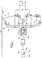
- the figure 4 shows a three-dimensional view of one embodiment of the arrangement of a housing 402, containing a sensor not shown, of a needle 404 and of a plate 406 (equivalent to the plate 210 of the figure 2 ) to a master cylinder 400.
- the plate 406 is made of plastic. It includes elastic lugs 408 allowing it to be snapped into the groove of the primary piston.
- the needle 404 is connected to the plate 406, at a conical projection 410 of the plate 406, via a helical spring 412 with contiguous turns.
- the diameter of the spring 412 is slightly smaller than the diameter of the projection 410 of the plate on which it is screwed in force or fits.
- the sensor (regardless of its type) is soldered or glued to the housing 402.
- Housing 402 is fixed to master cylinder 400 by means of a clip 414 or elastic curved blade, placed in force according to arrow 420 and which surrounds housing 402 to rest on two rails 416 of master cylinder 400.
- the housing 402 is immobilized parallel to the axis of the master cylinder 400 and perpendicular to this axis.
- the rail(s) 416 and the stop allowing to ensure an axial positioning without play of the housing on the master cylinder 400.
- the present invention is susceptible of many variants depending on various parameters such as, for example and without limitation, the choice of the type of sensor 230, the choice passing or open of the circuit crossing the sensor 230 according to the detection or not of braking and the positioning of the sensor 230 along the body of the master cylinder.
Landscapes
- Engineering & Computer Science (AREA)
- Transportation (AREA)
- Mechanical Engineering (AREA)
- Physics & Mathematics (AREA)
- General Physics & Mathematics (AREA)
- Braking Systems And Boosters (AREA)
- Braking Arrangements (AREA)
- Transmission Of Braking Force In Braking Systems (AREA)
- Braking Elements And Transmission Devices (AREA)
- Measurement Of Length, Angles, Or The Like Using Electric Or Magnetic Means (AREA)
- Regulating Braking Force (AREA)
- Automobile Manufacture Line, Endless Track Vehicle, Trailer (AREA)
Claims (11)
- Verfahren zur Erkennung des Bremsens eines Fahrzeugs, das mit einem Hauptbremszylinder (202, 400) und mit einem Primärkolben (200) ausgestattet ist, in welchem ein Bolzen (220, 305, 404), der parallel zu dem Primärkolben (200) angeordnet ist, um die Bewegungen des Primärkolbens (200) zu reproduzieren, und ein Sensor (230, 300) für die Bewegung des Bolzens (220, 305, 404) verwendet werden, um ein Bremsen zu erkennen,
dadurch gekennzeichnet, dass der Bolzen (220, 305, 404) mit dem Primärkolben des Hauptbremszylinders (200) über eine Platte (210, 406) fest verbunden ist, die sich im Gehäuse eines Servomotors (250) befindet, der dem Hauptbremszylinder (202, 400) zugeordnet ist. - Verfahren nach Anspruch 1, dadurch gekennzeichnet, dass der Bolzen (220, 305, 404) in einer Aufnahme (222) des Hauptbremszylinders (202, 400) gleitet.
- Verfahren nach Anspruch 2, dadurch gekennzeichnet, dass der Bolzen (220, 305, 404) mit der Platte (210, 406) über eine Feder (412) mit aneinander anliegenden Windungen fest verbunden ist.
- Verfahren nach Anspruch 1 oder 2, dadurch gekennzeichnet, dass der Sensor (230) einen Reed-Schalter verwendet, der für ein Magnetfeld empfindlich ist, welches in Abhängigkeit von der Bewegung des Bolzens (220, 404) variiert.
- Verfahren nach Anspruch 1 oder 2, dadurch gekennzeichnet, dass der Sensor (230) den Hall-Effekt nutzt um eine Bewegung des Bolzens (220, 404) zu erkennen.
- Verfahren nach einem der vorhergehenden Ansprüche, dadurch gekennzeichnet, dass der Bolzen (220, 404) in seinem nahe dem Sensor (230) befindlichen Ende ein Magnetfeld erzeugt, wobei dieser Sensor für das Magnetfeld des Bolzens empfindlich ist.
- Verfahren nach Anspruch 1, 2 oder 3, dadurch gekennzeichnet, dass der Sensor (230, 300) ein Sensor (230, 300) mit Kontaktgeber ist, der ein bewegliches Steuerelement (310) eines Schalters (302) umfasst, wobei der Bolzen (220, 305, 404) mit dem Steuerelement (310) in Kontakt kommt, wenn dieser Bolzen (220, 305, 404) sich bewegt.
- Verfahren nach einem der vorhergehenden Ansprüche, dadurch gekennzeichnet, dass sich der Sensor (230, 300) in einem Gehäuse (232, 402) befindet, das mit dem Hauptbremszylinder (202, 400) fest verbunden ist.
- Verfahren nach Anspruch 8, dadurch gekennzeichnet, dass das Gehäuse (232, 402) des Sensors (230, 300) dicht ist.
- Verfahren nach Anspruch 8 oder 9, dadurch gekennzeichnet, dass das Gehäuse (402) bezüglich des Hauptbremszylinders (400) über wenigstens eine Schiene (416) des Hauptbremszylinders (400) und einen Anschlag auf dieser Schiene (416) positioniert wird, wobei die Schiene (416) und der Anschlag ermöglichen, eine spielfreie axiale Positionierung sicherzustellen.
- Verfahren nach Anspruch 10, dadurch gekennzeichnet, dass das Gehäuse (402) an der Schiene (416) über eine elastische Klemme (414) befestigt wird, die das Gehäuse (402) umklammert.
Priority Applications (1)
| Application Number | Priority Date | Filing Date | Title |
|---|---|---|---|
| PL08101847T PL1972516T3 (pl) | 2007-03-22 | 2008-02-21 | Sposób i siłownik przeznaczone do wykrywania hamowania pojazdu i sposób wytwarzania takiego siłownika |
Applications Claiming Priority (1)
| Application Number | Priority Date | Filing Date | Title |
|---|---|---|---|
| FR0702099A FR2913937B1 (fr) | 2007-03-22 | 2007-03-22 | Procede et servomoteur destines a detecter le freinage d'un vehicule et procede de fabrication d'un tel servomoteur |
Publications (4)
| Publication Number | Publication Date |
|---|---|
| EP1972516A2 EP1972516A2 (de) | 2008-09-24 |
| EP1972516A3 EP1972516A3 (de) | 2016-11-16 |
| EP1972516B1 EP1972516B1 (de) | 2017-09-27 |
| EP1972516B2 true EP1972516B2 (de) | 2022-10-26 |
Family
ID=38716303
Family Applications (1)
| Application Number | Title | Priority Date | Filing Date |
|---|---|---|---|
| EP08101847.5A Active EP1972516B2 (de) | 2007-03-22 | 2008-02-21 | Verfahren und Servomotor zur Bremserkennung eines Fahrzeugs und Herstellungsverfahren eines solchen Servomotors |
Country Status (6)
| Country | Link |
|---|---|
| US (1) | US8136892B2 (de) |
| EP (1) | EP1972516B2 (de) |
| JP (1) | JP5165430B2 (de) |
| ES (1) | ES2654041T5 (de) |
| FR (1) | FR2913937B1 (de) |
| PL (1) | PL1972516T3 (de) |
Families Citing this family (14)
| Publication number | Priority date | Publication date | Assignee | Title |
|---|---|---|---|---|
| DE112008003309T5 (de) | 2007-12-03 | 2010-10-07 | Cts Corp., Elkhart | Linearer Positionssensor |
| DE112009003688B4 (de) * | 2008-11-26 | 2013-09-19 | Cts Corporation | Linearpositionssensor mit Drehblockiervorrichtung |
| DE112010004761T5 (de) * | 2009-12-09 | 2012-11-29 | Cts Corporation | Antriebs- und Sensoranordnung |
| DE102010031063A1 (de) * | 2010-07-07 | 2012-01-12 | Robert Bosch Gmbh | Sensoreinrichtung für ein Pedal und Verfahren zum Bereitstellen einer Information bezüglich einer Betätigung eines Pedals |
| US9435630B2 (en) | 2010-12-08 | 2016-09-06 | Cts Corporation | Actuator and linear position sensor assembly |
| FR2969092B1 (fr) * | 2010-12-15 | 2012-12-28 | Bosch Gmbh Robert | Dispositif d'assistance au freinage et vehicule automobile comportant un tel dispositif |
| KR101702844B1 (ko) * | 2014-02-27 | 2017-02-06 | 주식회사 만도 | 브레이크 마스터 실린더 |
| KR101447165B1 (ko) * | 2014-03-03 | 2014-10-10 | 한국델파이주식회사 | 브레이크 라이트 센서 모듈 |
| FR3037548B1 (fr) * | 2015-06-22 | 2019-05-17 | Robert Bosch Gmbh | Maitre-cylindre tandem |
| FR3037547B1 (fr) * | 2015-06-22 | 2019-07-05 | Robert Bosch Gmbh | Maitre-cylindre tandem equipe d'un commutateur de feux de stop |
| EP3387455A4 (de) | 2015-12-10 | 2019-08-14 | Bourns, Inc. | Weitreichender magnetischer näherungssensor |
| WO2018039122A1 (en) | 2016-08-24 | 2018-03-01 | Cts Corporation | Rotor for vehicle pedal with contacting sensor |
| CN106871936A (zh) * | 2017-02-17 | 2017-06-20 | 西安航空制动科技有限公司 | 一种指令传感器及其设计参数的确定方法 |
| DE102018006237A1 (de) | 2018-08-07 | 2020-02-13 | Lucas Automotive Gmbh | Elektromechinscher Bremskraftverstärker, Fahrzeugbremsanlage und Baugruppe hierfür |
Citations (15)
| Publication number | Priority date | Publication date | Assignee | Title |
|---|---|---|---|---|
| DE3124755A1 (de) † | 1981-06-24 | 1983-01-13 | Robert Bosch Gmbh, 7000 Stuttgart | Fahrzeugbremsanlage |
| DE3240680A1 (de) † | 1982-11-04 | 1984-05-10 | Robert Bosch Gmbh, 7000 Stuttgart | Hauptbremszylinder |
| DE3301042A1 (de) † | 1983-01-14 | 1984-07-19 | Robert Bosch Gmbh, 7000 Stuttgart | Hydraulischer zweikreis-tandem-hauptbremszylinder |
| DE3723916A1 (de) † | 1987-07-18 | 1989-01-26 | Daimler Benz Ag | Hydraulische zweikreis-bremsanlage |
| DE3723914A1 (de) † | 1987-07-18 | 1989-02-02 | Daimler Benz Ag | Bremsgeraet mit integriertem bremskraftverstaerker |
| DE3723839A1 (de) † | 1987-07-18 | 1989-02-02 | Daimler Benz Ag | Bremsgeraet |
| DE3723842A1 (de) † | 1987-07-18 | 1989-02-02 | Daimler Benz Ag | Bremsgeraet |
| DE3844068A1 (de) † | 1988-12-15 | 1990-08-23 | Bosch Gmbh Robert | Bremsanlage |
| DE3928874C1 (de) † | 1989-08-31 | 1991-01-10 | Mercedes-Benz Aktiengesellschaft, 7000 Stuttgart, De | |
| EP0480608A1 (de) † | 1990-10-10 | 1992-04-15 | Ford Motor Company Limited | Bremspedalweg-Warnsystem |
| DE19915832A1 (de) † | 1999-04-08 | 2000-07-06 | Bayerische Motoren Werke Ag | Fahrzeug mit einem Stellungsgeber |
| WO2002036400A1 (de) † | 2000-10-31 | 2002-05-10 | Continental Teves Ag & Co. Ohg | In einen hauptzylinder integrierter signalgeber mit hall-sensor |
| DE10323655A1 (de) † | 2002-08-27 | 2004-04-01 | Continental Teves Ag & Co. Ohg | Bremskraftverstärker |
| DE10137602B4 (de) † | 2001-08-01 | 2004-08-26 | Hella Kg Hueck & Co. | Elektrisches Bremssystem |
| KR100654335B1 (ko) † | 2003-05-13 | 2006-12-07 | 주식회사 만도 | 페달 스트로크센서의 설치구조 |
Family Cites Families (18)
| Publication number | Priority date | Publication date | Assignee | Title |
|---|---|---|---|---|
| FR2331774A1 (fr) * | 1975-11-12 | 1977-06-10 | Radiotechnique Compelec | Procede de reperage dynamique de positions particulieres de pieces mobiles a l'aide d'un cristal a effet hall et dispositifs de mise en oeuvre du procede |
| FR2388248A1 (fr) * | 1977-04-20 | 1978-11-17 | Radiotechnique Compelec | Detecteur de position a effet hall |
| DE3410736A1 (de) * | 1984-03-23 | 1985-10-03 | Wabco Westinghouse Fahrzeug | Analoger wegsensor |
| DE3511975A1 (de) * | 1985-04-02 | 1986-10-09 | Daimler-Benz Ag, 7000 Stuttgart | Hydraulischer bremskraftverstaerker |
| US5477675A (en) * | 1989-02-17 | 1995-12-26 | Nartron Corporation | Fluid power assist method and apparatus |
| JPH08226826A (ja) * | 1995-02-22 | 1996-09-03 | Mikuni Corp | 磁気式位置センサ |
| US6244049B1 (en) * | 1998-01-08 | 2001-06-12 | Jidosha Kiki Co., Ltd. | Brake system |
| US6304078B1 (en) * | 1998-12-09 | 2001-10-16 | Cts Corporation | Linear position sensor |
| JP2001001883A (ja) * | 1999-04-23 | 2001-01-09 | Bosch Braking Systems Co Ltd | ブレーキシステム |
| JP2001138885A (ja) * | 1999-11-18 | 2001-05-22 | Bosch Braking Systems Co Ltd | 電気制御ブレーキシステム |
| DE10133163A1 (de) * | 2001-02-20 | 2002-08-29 | Bosch Gmbh Robert | Messsystem |
| WO2002066307A2 (de) * | 2001-02-20 | 2002-08-29 | Robert Bosch Gmbh | Messsystem |
| US6619039B2 (en) * | 2001-04-25 | 2003-09-16 | Delphi Technologies, Inc. | Brake master cylinder-sensor system and method |
| US6652039B1 (en) * | 2002-09-30 | 2003-11-25 | Robert Bosch Corporation | Anti-lock braking system with accumulator volume monitoring |
| US7221151B2 (en) * | 2003-01-31 | 2007-05-22 | Delphi Technologies, Inc. | Magnetic array position sensor |
| FR2851538B1 (fr) * | 2003-02-21 | 2006-04-28 | Bosch Gmbh Robert | Maitre-cylindre de vehicule automobile avec dispositif de detection d'actionnement d'un systeme de freinage |
| DE102004014808A1 (de) * | 2003-04-07 | 2004-11-25 | Continental Teves Ag & Co. Ohg | Vorrichtung zur Überwachung von Position und Bewegung eines Bremspedals |
| EP1489385B1 (de) * | 2003-06-11 | 2016-07-20 | FTE automotive GmbH | Vorrichtung zur Sensierung der axialen Stellung eines ersten Bauteils, das relativ zu einem zweiten Bauteil bewegbar ist |
-
2007
- 2007-03-22 FR FR0702099A patent/FR2913937B1/fr not_active Expired - Fee Related
-
2008
- 2008-02-21 EP EP08101847.5A patent/EP1972516B2/de active Active
- 2008-02-21 ES ES08101847T patent/ES2654041T5/es active Active
- 2008-02-21 PL PL08101847T patent/PL1972516T3/pl unknown
- 2008-03-18 US US12/050,564 patent/US8136892B2/en active Active
- 2008-03-21 JP JP2008073358A patent/JP5165430B2/ja active Active
Patent Citations (15)
| Publication number | Priority date | Publication date | Assignee | Title |
|---|---|---|---|---|
| DE3124755A1 (de) † | 1981-06-24 | 1983-01-13 | Robert Bosch Gmbh, 7000 Stuttgart | Fahrzeugbremsanlage |
| DE3240680A1 (de) † | 1982-11-04 | 1984-05-10 | Robert Bosch Gmbh, 7000 Stuttgart | Hauptbremszylinder |
| DE3301042A1 (de) † | 1983-01-14 | 1984-07-19 | Robert Bosch Gmbh, 7000 Stuttgart | Hydraulischer zweikreis-tandem-hauptbremszylinder |
| DE3723842A1 (de) † | 1987-07-18 | 1989-02-02 | Daimler Benz Ag | Bremsgeraet |
| DE3723914A1 (de) † | 1987-07-18 | 1989-02-02 | Daimler Benz Ag | Bremsgeraet mit integriertem bremskraftverstaerker |
| DE3723839A1 (de) † | 1987-07-18 | 1989-02-02 | Daimler Benz Ag | Bremsgeraet |
| DE3723916A1 (de) † | 1987-07-18 | 1989-01-26 | Daimler Benz Ag | Hydraulische zweikreis-bremsanlage |
| DE3844068A1 (de) † | 1988-12-15 | 1990-08-23 | Bosch Gmbh Robert | Bremsanlage |
| DE3928874C1 (de) † | 1989-08-31 | 1991-01-10 | Mercedes-Benz Aktiengesellschaft, 7000 Stuttgart, De | |
| EP0480608A1 (de) † | 1990-10-10 | 1992-04-15 | Ford Motor Company Limited | Bremspedalweg-Warnsystem |
| DE19915832A1 (de) † | 1999-04-08 | 2000-07-06 | Bayerische Motoren Werke Ag | Fahrzeug mit einem Stellungsgeber |
| WO2002036400A1 (de) † | 2000-10-31 | 2002-05-10 | Continental Teves Ag & Co. Ohg | In einen hauptzylinder integrierter signalgeber mit hall-sensor |
| DE10137602B4 (de) † | 2001-08-01 | 2004-08-26 | Hella Kg Hueck & Co. | Elektrisches Bremssystem |
| DE10323655A1 (de) † | 2002-08-27 | 2004-04-01 | Continental Teves Ag & Co. Ohg | Bremskraftverstärker |
| KR100654335B1 (ko) † | 2003-05-13 | 2006-12-07 | 주식회사 만도 | 페달 스트로크센서의 설치구조 |
Also Published As
| Publication number | Publication date |
|---|---|
| FR2913937B1 (fr) | 2009-05-01 |
| JP2008230602A (ja) | 2008-10-02 |
| EP1972516A3 (de) | 2016-11-16 |
| ES2654041T3 (es) | 2018-02-12 |
| EP1972516B1 (de) | 2017-09-27 |
| US8136892B2 (en) | 2012-03-20 |
| FR2913937A1 (fr) | 2008-09-26 |
| EP1972516A2 (de) | 2008-09-24 |
| US20080230328A1 (en) | 2008-09-25 |
| PL1972516T3 (pl) | 2018-02-28 |
| ES2654041T5 (es) | 2023-03-14 |
| JP5165430B2 (ja) | 2013-03-21 |
Similar Documents
| Publication | Publication Date | Title |
|---|---|---|
| EP1972516B2 (de) | Verfahren und Servomotor zur Bremserkennung eines Fahrzeugs und Herstellungsverfahren eines solchen Servomotors | |
| EP0493154B1 (de) | Positionsmessvorrichtung für einem Stellglied eines pneumatischen Servomotors | |
| FR2586222A1 (fr) | Servo de frein pneumatique | |
| FR2951680A1 (fr) | Installation de freins a maitre-cylindre et servofrein sans tige de poussee | |
| FR2476577A1 (fr) | Servomoteur d'assistance au freinage | |
| EP1511662B1 (de) | Druckluftventil für bremsanlagen | |
| EP2253521B1 (de) | Servobremse mit Magnetventil | |
| FR2872767A1 (fr) | Maitre-cylindre comportant des moyens de detection du deplacement d'un element mobile | |
| FR2737457A1 (fr) | Servofrein d'automobile | |
| EP1635149B1 (de) | Einrichtung zur optischen Detektion der Betätigung der Bremsen eines Fahrzeugs | |
| EP2058196B1 (de) | Taster für Hilfsservomotor zur Bremsung | |
| FR2834253A1 (fr) | Dispositif de commande des feux de freinage sur un vehicule automobile | |
| EP2085278A1 (de) | Hauptbremszylinder für einen pneumatischen Bremskraftverstärker | |
| EP0467724A1 (de) | Verteiler für Druckflüssigkeit | |
| FR2919251A1 (fr) | Dispositif detecteur de freinage et de commande de feux arriere d'un vehicule. | |
| FR2834254A1 (fr) | Dispositif de commande des feux de freinage dans un vehicule automobile | |
| EP2384942B1 (de) | Hydraulisches Bremssystem mit einem verbesserten Steuerglied | |
| EP1375951A1 (de) | Kupplungssteuerungssystem | |
| FR2834255A1 (fr) | Dispositif de commande des feux de freinage sur un vehicule automobile | |
| EP1900584B1 (de) | Bremskraftverstärker | |
| FR2824038A1 (fr) | Dispositif de detection d'actionnement d'un systeme de freinage, et application | |
| EP2734427B1 (de) | Bremshilfevorrichtung für ein kraftfahrzeug | |
| WO1994001312A1 (fr) | Dispositif de transmission d'effort a appui plan | |
| FR2480690A1 (fr) | Servofrein hydraulique | |
| WO2004056636A1 (fr) | Servomoteur d'assistance au freinage, son procede de fabrication et dispositif |
Legal Events
| Date | Code | Title | Description |
|---|---|---|---|
| PUAI | Public reference made under article 153(3) epc to a published international application that has entered the european phase |
Free format text: ORIGINAL CODE: 0009012 |
|
| AK | Designated contracting states |
Kind code of ref document: A2 Designated state(s): AT BE BG CH CY CZ DE DK EE ES FI FR GB GR HR HU IE IS IT LI LT LU LV MC MT NL NO PL PT RO SE SI SK TR |
|
| AX | Request for extension of the european patent |
Extension state: AL BA MK RS |
|
| PUAL | Search report despatched |
Free format text: ORIGINAL CODE: 0009013 |
|
| AK | Designated contracting states |
Kind code of ref document: A3 Designated state(s): AT BE BG CH CY CZ DE DK EE ES FI FR GB GR HR HU IE IS IT LI LT LU LV MC MT NL NO PL PT RO SE SI SK TR |
|
| AX | Request for extension of the european patent |
Extension state: AL BA MK RS |
|
| RIC1 | Information provided on ipc code assigned before grant |
Ipc: G01D 5/14 20060101ALI20161010BHEP Ipc: B60T 13/52 20060101AFI20161010BHEP Ipc: B60T 11/16 20060101ALI20161010BHEP Ipc: B60Q 1/44 20060101ALI20161010BHEP |
|
| STAA | Information on the status of an ep patent application or granted ep patent |
Free format text: STATUS: REQUEST FOR EXAMINATION WAS MADE |
|
| 17P | Request for examination filed |
Effective date: 20170516 |
|
| RBV | Designated contracting states (corrected) |
Designated state(s): AT BE BG CH CY CZ DE DK EE ES FI FR GB GR HR HU IE IS IT LI LT LU LV MC MT NL NO PL PT RO SE SI SK TR |
|
| GRAP | Despatch of communication of intention to grant a patent |
Free format text: ORIGINAL CODE: EPIDOSNIGR1 |
|
| STAA | Information on the status of an ep patent application or granted ep patent |
Free format text: STATUS: GRANT OF PATENT IS INTENDED |
|
| AKX | Designation fees paid |
Designated state(s): AT BE BG CH CY CZ DE DK EE ES FI FR GB GR HR HU IE IS IT LI LT LU LV MC MT NL NO PL PT RO SE SI SK TR |
|
| AXX | Extension fees paid |
Extension state: MK Extension state: AL Extension state: BA Extension state: RS |
|
| INTG | Intention to grant announced |
Effective date: 20170628 |
|
| GRAS | Grant fee paid |
Free format text: ORIGINAL CODE: EPIDOSNIGR3 |
|
| GRAA | (expected) grant |
Free format text: ORIGINAL CODE: 0009210 |
|
| STAA | Information on the status of an ep patent application or granted ep patent |
Free format text: STATUS: THE PATENT HAS BEEN GRANTED |
|
| AK | Designated contracting states |
Kind code of ref document: B1 Designated state(s): AT BE BG CH CY CZ DE DK EE ES FI FR GB GR HR HU IE IS IT LI LT LU LV MC MT NL NO PL PT RO SE SI SK TR |
|
| REG | Reference to a national code |
Ref country code: GB Ref legal event code: FG4D Free format text: NOT ENGLISH |
|
| REG | Reference to a national code |
Ref country code: CH Ref legal event code: EP |
|
| REG | Reference to a national code |
Ref country code: AT Ref legal event code: REF Ref document number: 931644 Country of ref document: AT Kind code of ref document: T Effective date: 20171015 |
|
| REG | Reference to a national code |
Ref country code: IE Ref legal event code: FG4D Free format text: LANGUAGE OF EP DOCUMENT: FRENCH |
|
| REG | Reference to a national code |
Ref country code: DE Ref legal event code: R096 Ref document number: 602008052226 Country of ref document: DE |
|
| PG25 | Lapsed in a contracting state [announced via postgrant information from national office to epo] |
Ref country code: NO Free format text: LAPSE BECAUSE OF FAILURE TO SUBMIT A TRANSLATION OF THE DESCRIPTION OR TO PAY THE FEE WITHIN THE PRESCRIBED TIME-LIMIT Effective date: 20171227 Ref country code: SE Free format text: LAPSE BECAUSE OF FAILURE TO SUBMIT A TRANSLATION OF THE DESCRIPTION OR TO PAY THE FEE WITHIN THE PRESCRIBED TIME-LIMIT Effective date: 20170927 Ref country code: LT Free format text: LAPSE BECAUSE OF FAILURE TO SUBMIT A TRANSLATION OF THE DESCRIPTION OR TO PAY THE FEE WITHIN THE PRESCRIBED TIME-LIMIT Effective date: 20170927 Ref country code: HR Free format text: LAPSE BECAUSE OF FAILURE TO SUBMIT A TRANSLATION OF THE DESCRIPTION OR TO PAY THE FEE WITHIN THE PRESCRIBED TIME-LIMIT Effective date: 20170927 Ref country code: FI Free format text: LAPSE BECAUSE OF FAILURE TO SUBMIT A TRANSLATION OF THE DESCRIPTION OR TO PAY THE FEE WITHIN THE PRESCRIBED TIME-LIMIT Effective date: 20170927 |
|
| REG | Reference to a national code |
Ref country code: NL Ref legal event code: MP Effective date: 20170927 |
|
| REG | Reference to a national code |
Ref country code: ES Ref legal event code: FG2A Ref document number: 2654041 Country of ref document: ES Kind code of ref document: T3 Effective date: 20180212 Ref country code: LT Ref legal event code: MG4D |
|
| REG | Reference to a national code |
Ref country code: AT Ref legal event code: MK05 Ref document number: 931644 Country of ref document: AT Kind code of ref document: T Effective date: 20170927 |
|
| PG25 | Lapsed in a contracting state [announced via postgrant information from national office to epo] |
Ref country code: GR Free format text: LAPSE BECAUSE OF FAILURE TO SUBMIT A TRANSLATION OF THE DESCRIPTION OR TO PAY THE FEE WITHIN THE PRESCRIBED TIME-LIMIT Effective date: 20171228 Ref country code: LV Free format text: LAPSE BECAUSE OF FAILURE TO SUBMIT A TRANSLATION OF THE DESCRIPTION OR TO PAY THE FEE WITHIN THE PRESCRIBED TIME-LIMIT Effective date: 20170927 Ref country code: BG Free format text: LAPSE BECAUSE OF FAILURE TO SUBMIT A TRANSLATION OF THE DESCRIPTION OR TO PAY THE FEE WITHIN THE PRESCRIBED TIME-LIMIT Effective date: 20171227 |
|
| PG25 | Lapsed in a contracting state [announced via postgrant information from national office to epo] |
Ref country code: NL Free format text: LAPSE BECAUSE OF FAILURE TO SUBMIT A TRANSLATION OF THE DESCRIPTION OR TO PAY THE FEE WITHIN THE PRESCRIBED TIME-LIMIT Effective date: 20170927 |
|
| PG25 | Lapsed in a contracting state [announced via postgrant information from national office to epo] |
Ref country code: CZ Free format text: LAPSE BECAUSE OF FAILURE TO SUBMIT A TRANSLATION OF THE DESCRIPTION OR TO PAY THE FEE WITHIN THE PRESCRIBED TIME-LIMIT Effective date: 20170927 Ref country code: RO Free format text: LAPSE BECAUSE OF FAILURE TO SUBMIT A TRANSLATION OF THE DESCRIPTION OR TO PAY THE FEE WITHIN THE PRESCRIBED TIME-LIMIT Effective date: 20170927 |
|
| PG25 | Lapsed in a contracting state [announced via postgrant information from national office to epo] |
Ref country code: IS Free format text: LAPSE BECAUSE OF FAILURE TO SUBMIT A TRANSLATION OF THE DESCRIPTION OR TO PAY THE FEE WITHIN THE PRESCRIBED TIME-LIMIT Effective date: 20180127 Ref country code: EE Free format text: LAPSE BECAUSE OF FAILURE TO SUBMIT A TRANSLATION OF THE DESCRIPTION OR TO PAY THE FEE WITHIN THE PRESCRIBED TIME-LIMIT Effective date: 20170927 Ref country code: SK Free format text: LAPSE BECAUSE OF FAILURE TO SUBMIT A TRANSLATION OF THE DESCRIPTION OR TO PAY THE FEE WITHIN THE PRESCRIBED TIME-LIMIT Effective date: 20170927 Ref country code: AT Free format text: LAPSE BECAUSE OF FAILURE TO SUBMIT A TRANSLATION OF THE DESCRIPTION OR TO PAY THE FEE WITHIN THE PRESCRIBED TIME-LIMIT Effective date: 20170927 |
|
| REG | Reference to a national code |
Ref country code: DE Ref legal event code: R026 Ref document number: 602008052226 Country of ref document: DE |
|
| PLBI | Opposition filed |
Free format text: ORIGINAL CODE: 0009260 |
|
| PG25 | Lapsed in a contracting state [announced via postgrant information from national office to epo] |
Ref country code: DK Free format text: LAPSE BECAUSE OF FAILURE TO SUBMIT A TRANSLATION OF THE DESCRIPTION OR TO PAY THE FEE WITHIN THE PRESCRIBED TIME-LIMIT Effective date: 20170927 |
|
| 26 | Opposition filed |
Opponent name: LUCAS AUTOMOTIVE GMBH Effective date: 20180622 |
|
| PLAX | Notice of opposition and request to file observation + time limit sent |
Free format text: ORIGINAL CODE: EPIDOSNOBS2 |
|
| REG | Reference to a national code |
Ref country code: CH Ref legal event code: PL |
|
| PG25 | Lapsed in a contracting state [announced via postgrant information from national office to epo] |
Ref country code: MT Free format text: LAPSE BECAUSE OF FAILURE TO SUBMIT A TRANSLATION OF THE DESCRIPTION OR TO PAY THE FEE WITHIN THE PRESCRIBED TIME-LIMIT Effective date: 20170927 Ref country code: MC Free format text: LAPSE BECAUSE OF FAILURE TO SUBMIT A TRANSLATION OF THE DESCRIPTION OR TO PAY THE FEE WITHIN THE PRESCRIBED TIME-LIMIT Effective date: 20170927 |
|
| GBPC | Gb: european patent ceased through non-payment of renewal fee |
Effective date: 20180221 |
|
| REG | Reference to a national code |
Ref country code: IE Ref legal event code: MM4A |
|
| REG | Reference to a national code |
Ref country code: BE Ref legal event code: MM Effective date: 20180228 |
|
| PG25 | Lapsed in a contracting state [announced via postgrant information from national office to epo] |
Ref country code: LI Free format text: LAPSE BECAUSE OF NON-PAYMENT OF DUE FEES Effective date: 20180228 Ref country code: CH Free format text: LAPSE BECAUSE OF NON-PAYMENT OF DUE FEES Effective date: 20180228 Ref country code: SI Free format text: LAPSE BECAUSE OF FAILURE TO SUBMIT A TRANSLATION OF THE DESCRIPTION OR TO PAY THE FEE WITHIN THE PRESCRIBED TIME-LIMIT Effective date: 20170927 Ref country code: LU Free format text: LAPSE BECAUSE OF NON-PAYMENT OF DUE FEES Effective date: 20180221 |
|
| REG | Reference to a national code |
Ref country code: FR Ref legal event code: ST Effective date: 20181031 |
|
| PLBB | Reply of patent proprietor to notice(s) of opposition received |
Free format text: ORIGINAL CODE: EPIDOSNOBS3 |
|
| PG25 | Lapsed in a contracting state [announced via postgrant information from national office to epo] |
Ref country code: IE Free format text: LAPSE BECAUSE OF NON-PAYMENT OF DUE FEES Effective date: 20180221 |
|
| PG25 | Lapsed in a contracting state [announced via postgrant information from national office to epo] |
Ref country code: FR Free format text: LAPSE BECAUSE OF NON-PAYMENT OF DUE FEES Effective date: 20180228 Ref country code: BE Free format text: LAPSE BECAUSE OF NON-PAYMENT OF DUE FEES Effective date: 20180228 Ref country code: GB Free format text: LAPSE BECAUSE OF NON-PAYMENT OF DUE FEES Effective date: 20180221 |
|
| PG25 | Lapsed in a contracting state [announced via postgrant information from national office to epo] |
Ref country code: TR Free format text: LAPSE BECAUSE OF FAILURE TO SUBMIT A TRANSLATION OF THE DESCRIPTION OR TO PAY THE FEE WITHIN THE PRESCRIBED TIME-LIMIT Effective date: 20170927 |
|
| RAP2 | Party data changed (patent owner data changed or rights of a patent transferred) |
Owner name: ROBERT BOSCH GMBH |
|
| PG25 | Lapsed in a contracting state [announced via postgrant information from national office to epo] |
Ref country code: PT Free format text: LAPSE BECAUSE OF FAILURE TO SUBMIT A TRANSLATION OF THE DESCRIPTION OR TO PAY THE FEE WITHIN THE PRESCRIBED TIME-LIMIT Effective date: 20170927 Ref country code: HU Free format text: LAPSE BECAUSE OF FAILURE TO SUBMIT A TRANSLATION OF THE DESCRIPTION OR TO PAY THE FEE WITHIN THE PRESCRIBED TIME-LIMIT; INVALID AB INITIO Effective date: 20080221 |
|
| PG25 | Lapsed in a contracting state [announced via postgrant information from national office to epo] |
Ref country code: CY Free format text: LAPSE BECAUSE OF FAILURE TO SUBMIT A TRANSLATION OF THE DESCRIPTION OR TO PAY THE FEE WITHIN THE PRESCRIBED TIME-LIMIT Effective date: 20170927 |
|
| PLAB | Opposition data, opponent's data or that of the opponent's representative modified |
Free format text: ORIGINAL CODE: 0009299OPPO |
|
| R26 | Opposition filed (corrected) |
Opponent name: ZF ACTIVE SAFETY GMBH Effective date: 20180622 |
|
| RIC2 | Information provided on ipc code assigned after grant |
Ipc: B60T 11/16 20060101ALI20210126BHEP Ipc: G01D 5/251 20060101AFI20210126BHEP Ipc: B60T 13/52 20060101ALI20210126BHEP |
|
| PLAB | Opposition data, opponent's data or that of the opponent's representative modified |
Free format text: ORIGINAL CODE: 0009299OPPO |
|
| R26 | Opposition filed (corrected) |
Opponent name: ZF ACTIVE SAFETY GMBH Effective date: 20180622 |
|
| APBM | Appeal reference recorded |
Free format text: ORIGINAL CODE: EPIDOSNREFNO |
|
| APBP | Date of receipt of notice of appeal recorded |
Free format text: ORIGINAL CODE: EPIDOSNNOA2O |
|
| APAH | Appeal reference modified |
Free format text: ORIGINAL CODE: EPIDOSCREFNO |
|
| APBM | Appeal reference recorded |
Free format text: ORIGINAL CODE: EPIDOSNREFNO |
|
| APBP | Date of receipt of notice of appeal recorded |
Free format text: ORIGINAL CODE: EPIDOSNNOA2O |
|
| APBQ | Date of receipt of statement of grounds of appeal recorded |
Free format text: ORIGINAL CODE: EPIDOSNNOA3O |
|
| APBQ | Date of receipt of statement of grounds of appeal recorded |
Free format text: ORIGINAL CODE: EPIDOSNNOA3O |
|
| APBC | Information on closure of appeal procedure deleted |
Free format text: ORIGINAL CODE: EPIDOSDNOA9O |
|
| APBU | Appeal procedure closed |
Free format text: ORIGINAL CODE: EPIDOSNNOA9O |
|
| APBU | Appeal procedure closed |
Free format text: ORIGINAL CODE: EPIDOSNNOA9O |
|
| PGFP | Annual fee paid to national office [announced via postgrant information from national office to epo] |
Ref country code: PL Payment date: 20220209 Year of fee payment: 15 |
|
| PUAH | Patent maintained in amended form |
Free format text: ORIGINAL CODE: 0009272 |
|
| STAA | Information on the status of an ep patent application or granted ep patent |
Free format text: STATUS: PATENT MAINTAINED AS AMENDED |
|
| 27A | Patent maintained in amended form |
Effective date: 20221026 |
|
| AK | Designated contracting states |
Kind code of ref document: B2 Designated state(s): AT BE BG CH CY CZ DE DK EE ES FI FR GB GR HR HU IE IS IT LI LT LU LV MC MT NL NO PL PT RO SE SI SK TR |
|
| REG | Reference to a national code |
Ref country code: DE Ref legal event code: R102 Ref document number: 602008052226 Country of ref document: DE |
|
| REG | Reference to a national code |
Ref country code: ES Ref legal event code: DC2A Ref document number: 2654041 Country of ref document: ES Kind code of ref document: T5 Effective date: 20230314 |
|
| PGFP | Annual fee paid to national office [announced via postgrant information from national office to epo] |
Ref country code: IT Payment date: 20230228 Year of fee payment: 16 |
|
| PGFP | Annual fee paid to national office [announced via postgrant information from national office to epo] |
Ref country code: DE Payment date: 20230426 Year of fee payment: 16 |
|
| REG | Reference to a national code |
Ref country code: DE Ref legal event code: R084 Ref document number: 602008052226 Country of ref document: DE |
|
| PGFP | Annual fee paid to national office [announced via postgrant information from national office to epo] |
Ref country code: ES Payment date: 20240319 Year of fee payment: 17 |
|
| PGFP | Annual fee paid to national office [announced via postgrant information from national office to epo] |
Ref country code: CZ Payment date: 20240214 Year of fee payment: 17 |