EP1972135B1 - Projektionsvorrichtung und projektionsverfahren - Google Patents
Projektionsvorrichtung und projektionsverfahren Download PDFInfo
- Publication number
- EP1972135B1 EP1972135B1 EP07706866A EP07706866A EP1972135B1 EP 1972135 B1 EP1972135 B1 EP 1972135B1 EP 07706866 A EP07706866 A EP 07706866A EP 07706866 A EP07706866 A EP 07706866A EP 1972135 B1 EP1972135 B1 EP 1972135B1
- Authority
- EP
- European Patent Office
- Prior art keywords
- light source
- color wheel
- color
- period
- optical path
- Prior art date
- Legal status (The legal status is an assumption and is not a legal conclusion. Google has not performed a legal analysis and makes no representation as to the accuracy of the status listed.)
- Ceased
Links
- 238000000034 method Methods 0.000 title claims description 8
- 230000003287 optical effect Effects 0.000 claims abstract description 45
- 230000002093 peripheral effect Effects 0.000 claims abstract description 5
- 238000007599 discharging Methods 0.000 claims description 2
- 230000004044 response Effects 0.000 description 6
- 238000010586 diagram Methods 0.000 description 5
- QSHDDOUJBYECFT-UHFFFAOYSA-N mercury Chemical compound [Hg] QSHDDOUJBYECFT-UHFFFAOYSA-N 0.000 description 5
- 230000001360 synchronised effect Effects 0.000 description 5
- 238000001816 cooling Methods 0.000 description 4
- 238000001514 detection method Methods 0.000 description 3
- 230000002411 adverse Effects 0.000 description 2
- 238000005516 engineering process Methods 0.000 description 2
- 238000004904 shortening Methods 0.000 description 2
- 238000006243 chemical reaction Methods 0.000 description 1
- 238000009826 distribution Methods 0.000 description 1
- 238000010891 electric arc Methods 0.000 description 1
- 238000010438 heat treatment Methods 0.000 description 1
- 238000003780 insertion Methods 0.000 description 1
- 230000037431 insertion Effects 0.000 description 1
Images

Classifications
-
- H—ELECTRICITY
- H04—ELECTRIC COMMUNICATION TECHNIQUE
- H04N—PICTORIAL COMMUNICATION, e.g. TELEVISION
- H04N9/00—Details of colour television systems
- H04N9/12—Picture reproducers
- H04N9/31—Projection devices for colour picture display, e.g. using electronic spatial light modulators [ESLM]
-
- G—PHYSICS
- G03—PHOTOGRAPHY; CINEMATOGRAPHY; ANALOGOUS TECHNIQUES USING WAVES OTHER THAN OPTICAL WAVES; ELECTROGRAPHY; HOLOGRAPHY
- G03B—APPARATUS OR ARRANGEMENTS FOR TAKING PHOTOGRAPHS OR FOR PROJECTING OR VIEWING THEM; APPARATUS OR ARRANGEMENTS EMPLOYING ANALOGOUS TECHNIQUES USING WAVES OTHER THAN OPTICAL WAVES; ACCESSORIES THEREFOR
- G03B21/00—Projectors or projection-type viewers; Accessories therefor
- G03B21/14—Details
-
- G—PHYSICS
- G02—OPTICS
- G02B—OPTICAL ELEMENTS, SYSTEMS OR APPARATUS
- G02B26/00—Optical devices or arrangements for the control of light using movable or deformable optical elements
-
- G—PHYSICS
- G02—OPTICS
- G02B—OPTICAL ELEMENTS, SYSTEMS OR APPARATUS
- G02B27/00—Optical systems or apparatus not provided for by any of the groups G02B1/00 - G02B26/00, G02B30/00
- G02B27/18—Optical systems or apparatus not provided for by any of the groups G02B1/00 - G02B26/00, G02B30/00 for optical projection, e.g. combination of mirror and condenser and objective
-
- G—PHYSICS
- G02—OPTICS
- G02B—OPTICAL ELEMENTS, SYSTEMS OR APPARATUS
- G02B5/00—Optical elements other than lenses
- G02B5/20—Filters
-
- G—PHYSICS
- G03—PHOTOGRAPHY; CINEMATOGRAPHY; ANALOGOUS TECHNIQUES USING WAVES OTHER THAN OPTICAL WAVES; ELECTROGRAPHY; HOLOGRAPHY
- G03B—APPARATUS OR ARRANGEMENTS FOR TAKING PHOTOGRAPHS OR FOR PROJECTING OR VIEWING THEM; APPARATUS OR ARRANGEMENTS EMPLOYING ANALOGOUS TECHNIQUES USING WAVES OTHER THAN OPTICAL WAVES; ACCESSORIES THEREFOR
- G03B21/00—Projectors or projection-type viewers; Accessories therefor
- G03B21/14—Details
- G03B21/20—Lamp housings
- G03B21/2053—Intensity control of illuminating light
-
- G—PHYSICS
- G03—PHOTOGRAPHY; CINEMATOGRAPHY; ANALOGOUS TECHNIQUES USING WAVES OTHER THAN OPTICAL WAVES; ELECTROGRAPHY; HOLOGRAPHY
- G03B—APPARATUS OR ARRANGEMENTS FOR TAKING PHOTOGRAPHS OR FOR PROJECTING OR VIEWING THEM; APPARATUS OR ARRANGEMENTS EMPLOYING ANALOGOUS TECHNIQUES USING WAVES OTHER THAN OPTICAL WAVES; ACCESSORIES THEREFOR
- G03B33/00—Colour photography, other than mere exposure or projection of a colour film
- G03B33/08—Sequential recording or projection
-
- H—ELECTRICITY
- H04—ELECTRIC COMMUNICATION TECHNIQUE
- H04N—PICTORIAL COMMUNICATION, e.g. TELEVISION
- H04N9/00—Details of colour television systems
- H04N9/12—Picture reproducers
- H04N9/31—Projection devices for colour picture display, e.g. using electronic spatial light modulators [ESLM]
- H04N9/3102—Projection devices for colour picture display, e.g. using electronic spatial light modulators [ESLM] using two-dimensional electronic spatial light modulators
- H04N9/3111—Projection devices for colour picture display, e.g. using electronic spatial light modulators [ESLM] using two-dimensional electronic spatial light modulators for displaying the colours sequentially, e.g. by using sequentially activated light sources
- H04N9/3114—Projection devices for colour picture display, e.g. using electronic spatial light modulators [ESLM] using two-dimensional electronic spatial light modulators for displaying the colours sequentially, e.g. by using sequentially activated light sources by using a sequential colour filter producing one colour at a time
-
- H—ELECTRICITY
- H04—ELECTRIC COMMUNICATION TECHNIQUE
- H04N—PICTORIAL COMMUNICATION, e.g. TELEVISION
- H04N9/00—Details of colour television systems
- H04N9/12—Picture reproducers
- H04N9/31—Projection devices for colour picture display, e.g. using electronic spatial light modulators [ESLM]
- H04N9/3141—Constructional details thereof
- H04N9/315—Modulator illumination systems
- H04N9/3155—Modulator illumination systems for controlling the light source
-
- G—PHYSICS
- G03—PHOTOGRAPHY; CINEMATOGRAPHY; ANALOGOUS TECHNIQUES USING WAVES OTHER THAN OPTICAL WAVES; ELECTROGRAPHY; HOLOGRAPHY
- G03B—APPARATUS OR ARRANGEMENTS FOR TAKING PHOTOGRAPHS OR FOR PROJECTING OR VIEWING THEM; APPARATUS OR ARRANGEMENTS EMPLOYING ANALOGOUS TECHNIQUES USING WAVES OTHER THAN OPTICAL WAVES; ACCESSORIES THEREFOR
- G03B21/00—Projectors or projection-type viewers; Accessories therefor
- G03B21/14—Details
- G03B21/32—Details specially adapted for motion-picture projection
- G03B21/40—Eliminating or reducing effect of flicker
Definitions
- the present invention relates to a projection device and a projection method capable of forming an image of primary color components in a time division manner by use of a white light source and a color wheel to thereby project a color image.
- each primary color component of light from a white light source is transmitted in a time division manner via a member which is referred to as a color wheel and which is provided with at least primary color filters of red (R), green (G) and blue (B), and the primary color light is successively reflected in the time division manner by an optical modulation element for displaying a monochromatic image.
- an optical modulation element for displaying a monochromatic image.
- a high-pressure mercury vapor lamp which performs arc discharge is used as the white light source, and the mercury vapor lamp is driven with an alternating current.
- a rotation frequency of the color wheel is set to be integer times as much as a driving frequency of the white light source.
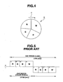
- FIG. 4 illustrates a constitution of a general color wheel 1.
- an arrow r indicates a rotating direction.
- the wheel 1 employs a constitution of four segments in total in which a white (W) (practically transparent) segment is disposed in addition to the red (R), green (G) and blue (B) segments.
- W white
- R red
- G green
- B blue
- Rotation driving of the color wheel 1 is synchronized with a frame frequency of an image to be projected, and it is set to 50 (PAL)/60 (NTSC) [Hz] in many cases.
- Driving (discharge) of the lamp which is the light source causes a problem such as flicker of the image, if the driving of the lamp is not synchronized with this frame frequency of the image. Therefore, the general light source lamp is always driven at 50/60 [Hz].
- FIG. 5 shows a driving timing of the general color wheel in response to a driving period of the light source lamp.
- the frequency of the light source lamp is set to 60 [Hz].
- the driving frequency of the color wheel 1 is doubled to 120 [Hz] will be exemplified.
- the light source lamp is driven with one polarity, for example, a plus (+) polarity.
- one polarity for example, a plus (+) polarity.
- the light source lamp is driven with the other polarity, for example, a minus (-) polarity.
- the segments R, G, B and W of the color wheel are similarly inserted into the optical path in this order.
- the rotation frequency of the color wheel it is appropriate to set the rotation frequency of the color wheel to be integer times as much as the driving frequency of the lamp.
- the rotation frequency of the color wheel it is appropriate to set the rotation frequency of the color wheel to be integer times as much as the driving frequency of the lamp.
- the driving frequency of the lamp depends on a structure and a performance of the lamp. In a case where a structure having the high emission luminance is simply employed, there is a possibility that the lamp is required to be driven at a frequency which deviates from the synchronization frequency.
- the driving frequency of the lamp is set to be, for example, 0.75 time as much as the rotation frequency of the color wheel.
- the rotation frequency of the color wheel is not necessarily set to be integer times as much as the driving frequency of the lamp (e.g., Jpn. Pat. Appln. KOKAI Publication No. 2003-162001 ).
- the present invention is directed to a projection device and a projection method that improves a brightness of a projected image without shortening the life of a lamp and damaging the quality of image due to a flicker.
- a projection device comprises a light source which emits white light by alternating-current discharge, a color wheel which is inserted into an optical path of the light source and in which a plurality of color segments are formed at arbitrary sector angles along a peripheral direction of the color wheel, the color segments being configured to transmit a plurality of wavelength band components in the white light in a time division manner by rotating the color wheel, a color wheel driving unit which rotates the color wheel at a constant speed, and a light source driving unit which alternating-current discharges the light source at a period shorter than the rotation period of the color wheel while reversing the polarity at a timing to switch the segment of the color wheel inserted into the optical path.
- a projection method of a projection device comprising a light source which emits white light by alternating-current discharge, and a color wheel which is inserted into an optical path of the light source and in which a plurality of color segments are formed at arbitrary sector angles along a peripheral direction of the color wheel, the color segments being configured to transmit a plurality of wavelength band components in the white light in a time division manner by rotating the color wheel, the method comprises:
- FIG. 1 shows a circuit constitution of the data projection device 10 according to the present embodiment.
- An image signal of various standards which is input from an input/output connector unit 11 is supplied to an image conversion unit 13 via an input/output interface (I/F) 12 and a system bus SB, and converted into an image signal having a predetermined format.
- the converted signal is supplied to a projection encoder 14.
- the projection encoder 14 develops and stores the supplied image signal in a video RAM 15, generates a video signal from the image signal stored in the video RAM 15, and then outputs the video signal to a projection driving unit 16.
- the projection driving unit 16 In response to the supplied image signal, the projection driving unit 16 appropriately drives in a high speed time division manner a micro mirror element 17 which is, for example, a spatial optical modulation element (SOM).
- the driving frequency is based on a product of a frame rate of, for example, 120 [frames/second], the number of the divided color components, and the number of display gradations.
- the lighting of the light source lamp 19 is controlled by a lamp driving unit 24, and a detection output of a temperature sensor 25 disposed in the vicinity of the light source lamp 19 of the reflector 18 is also supplied to the lamp driving unit 24, and converted into a digital signal therein.
- a motor (M) 26 which rotates the color wheel 20 rotates at a constant speed in accordance with a voltage supplied from a color wheel driving unit 27.
- Rotating positions of the color wheel 20, specifically, switch positions which are boundaries between the segments of red (R), green (G), blue (B) and white (W) are detected by a position sensor 28, and the resultant detection output is supplied to the color wheel driving unit 27 and digitized therein.
- the control unit 29 is constituted of a CPU, a nonvolatile memory which stores an operation program to be executed by the CPU during a projecting operation, a work memory and the like.
- the control unit 29 is also connected to a sound processing unit 30 via the system bus SB.
- the sound processing unit 30 includes a sound source circuit for a PCM sound source or the like.
- the sound processing unit 30 converts sound data given during the projecting operation into analog data, and drives a speaker 31 to amplify and emit sound or generate beep sound or the like if necessary.
- each key operation signal in a key switch (SW) unit 32 disposed on an upper surface of a housing of the data projection device 10 is directly input into the control unit 29.
- a signal from an Ir receiving unit 33 is also directly input into the control unit 29.
- the Ir receiving unit 33 receives an operation signal from a remote controller (not shown) attached to the data projection device 10 or an infrared modulation signal which meets the IrDA standard from an external apparatus via Ir receiving window portions arranged in a front surface and a rear surface of the housing of the data projection device 10, respectively. Then, the Ir receiving unit 33 converts the received signal into a code signal to send the signal to the control unit 29.
- the driving of the light source lamp 19 is controlled in two stages of a usual light emission time and a low-luminance light emission time. That is, at the usual light emission time, a rated voltage is applied to the light source lamp 19 to drive the lamp, and a cooling operation by a cooling fan or the like (not shown in FIG. 1 ) is also executed on rated conditions. On the other hand, at the low-luminance light emission time, a predetermined voltage, which is lower than the rated voltage and does not adversely affect a life and the like of the lamp, is applied to the light source lamp 19 to drive the lamp. The cooling operation by the cooling fan or the like is executed on conditions lower than the rated conditions in accordance with a lower heating value due to the lower light emission luminance. In consequence, the whole power consumption and generation of noise are reduced.
- the color wheel 20 has four segments of, for example, red (R), green (G), blue (B) and white (W).
- R red
- G green
- B blue
- W white
- sector angles of sector-shaped segments R, G, B and W are arbitrarily set so that the sector angles differ from one another and a sum of the angles is 360 degrees.
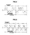
- FIG. 2 illustrates a light emission driving period of the light source lamp 19 and a color wheel driving timing of the color wheel 20 at the usual light emission time.
- the color wheel 20 is rotated at a constant speed, and a rotation period of the wheel 20 is fixed at, for example, 1/120 [sec].
- the light source lamp 19 is driven with reversing a polarity in synchronization with a timing to switch each segment of the color wheel 20 inserted into an optical path under controls of the control unit 29 and the lamp driving unit 24.
- one driving direction of the lamp is referred to as plus, and the other driving direction obtained by reversing a polarity is referred to as minus.
- the light source lamp 19 is driven with the polarity of the plus direction. Subsequently, while the segments G, B are inserted into the optical path, the lamp is driven with the reversed polarity of the minus direction.
- the light source lamp 19 is driven with the polarity of the plus direction. Subsequently, during the second rotation period, and while the segment R is inserted into the optical path, the lamp is driven with the reversed polarity of the minus direction.
- the light source lamp 19 is driven with the polarity of the plus direction. Subsequently, while the segment W is inserted into the optical path, the lamp is driven with the reversed polarity of the minus direction.
- the period during which the color wheel 20 rotates twice is regarded as one driving pattern cycle, and the polarity reverse timing of the driving of the light source lamp 19 is synchronized with the timing to switch the segment of the color wheel 20.
- the position sensor 28 detects a rotating position of the color wheel 20, and the color wheel driving unit 27 digitizes the resultant detection signal and supplies the digitized signal to the control unit 29. Then, the control unit 29 supplies, to the lamp driving unit 24, a driving signal for switching the segment in accordance with the arbitrarily set sector angle of each segment of the color wheel 20, and in response to this driving signal, the lamp driving unit 24 lights the light source lamp 19 to control the polarity reverse timing of the lamp.
- the period during which the color wheel 20 rotates twice is regarded as one driving pattern cycle, and the polarity reverse timing of the driving of the light source lamp 19 is synchronized with the timing to switch the segment of the color wheel 20.
- the driving of the lamp 19 is controlled so as to include three periods.
- FIG. 3 illustrates a light emission driving period of the light source lamp 19 and a color wheel driving timing of the color wheel 20 at the low-luminance light emission time.
- the color wheel 20 is rotated at the constant speed similar to that of the usual light emission time, and the rotation period of the color wheel 20 is fixed at, for example, 1/120 [sec].
- the light source lamp 19 is driven with reversing a polarity in synchronization with the timing to switch the segment of the color wheel 20 inserted into the optical path under the controls of the control unit 29 and the lamp driving unit 24.
- the light source lamp 19 is driven with the polarity of the plus direction. Subsequently, while the segment G is inserted into the optical path, the lamp 19 is driven with the reversed polarity of the minus direction.
- the light source lamp 19 is driven with the polarity of the plus direction. Subsequently, during the first half of a time when the segment W is inserted into the optical path, the lamp 19 is driven with the reversed polarity of the minus direction.
- the light source lamp 19 is driven with the polarity of the plus direction. Subsequently, during the second rotation period, and while the segment R is inserted into the optical path, the lamp 19 is driven with the reversed polarity of the minus direction.
- the light source lamp 19 is driven with the polarity of the plus direction. Subsequently, while the segment B is inserted into the optical path, the lamp 19 is driven with the reversed polarity of the minus direction.
- the light source lamp 19 is driven with the polarity of the plus direction.
- the lamp 19 is driven with the reversed polarity of the minus direction.
- the period during which the color wheel 20 rotates twice is regarded as one driving pattern cycle, and the polarity reverse timing of the driving of the light source lamp 19 is synchronized with the timing to switch the segment of the color wheel 20.
- the driving of the lamp 19 is controlled so as to include five periods.
- the electric discharge period (light emission period) of the lamp 19 in the usual light emission time is not equal to that in the low-luminance light emission time, and the lamp 19 is driven with reversing a polarity in synchronization with the timing to switch the segment of the color wheel 20 inserted into the optical path.
- the number of electric discharge times (light emission times) of the light source lamp 19 per unit time can be increased in accordance with setting of time widths (the sector angles) of the respective segments constituting the color wheel 20. Accordingly, a temperature control of the light source lamp 19 is very easy.
- the light source lamp 19 is synchronously driven so as to alternately reverse the polarity of the light source lamp 19 during the insertion of the segment into the optical path in consideration of the time widths of the plurality of color segments R, G, B and W constituting the color wheel 20, the occurrence of the flicker, color drift and the like can be prevented.
- the time period when the segment W is inserted into the optical path is divided into two sub periods, and the light source lamp 19 is driven so that the polarity of the light source lamp 19 is reversed in synchronism with the sub periods.
- the number of the electric discharge times of the light source lamp 19 is increased to thereby prevent a temperature of a terminal electrode of the lamp 19 from lowering below an allowable range, without adversely influencing a balance of the color components or the like.
- a possible range of the temperature control can further be broadened to previously prevent a life of the light source lamp 19 from shortening.
- the light source lamp 19 is constituted of the high-pressure mercury vapor lamp, but the present invention is not limited to this embodiment.
- the present invention can similarly employ another lamp such as a super high-pressure mercury vapor lamp having a higher pressure in a lamp tube, as long as the lamp is of an electric discharge type which emits the light while reversing the polarity by the alternating-current driving.
Landscapes
- Physics & Mathematics (AREA)
- General Physics & Mathematics (AREA)
- Engineering & Computer Science (AREA)
- Multimedia (AREA)
- Signal Processing (AREA)
- Optics & Photonics (AREA)
- Projection Apparatus (AREA)
- Video Image Reproduction Devices For Color Tv Systems (AREA)
- Mechanical Light Control Or Optical Switches (AREA)
- Optical Filters (AREA)
Claims (8)
- Projektionsvorrichtung, die umfasst:eine Lichtquelle (19), die durch Wechselstromentladung weißes Licht emittiert;ein Farbrad (20), das in einen Lichtweg der Lichtquelle eingesetzt ist und in dem eine Vielzahl von Farbsegmenten an beliebigen Sektorwinkeln in einer Umfangsrichtung des Farbrades ausgebildet sind, wobei die Farbsegmente so eingerichtet sind, dass sie eine Vielzahl von Wellenlängenband-Komponenten in dem weißen Licht im Zeitteilverfahren durchlassen, indem das Farbrad gedreht wird;eine Farbrad-Antriebseinheit (27), die das Farbrad mit einer konstanten Geschwindigkeit dreht; undeine Lichtquellen-Ansteuereinheit (24), die Wechselstromentladung der Lichtquelle mit einer Periode bewirkt, die kürzer ist als die Drehperiode des Farbrades, und dabei die Polarität zu einem Zeitpunkt umkehrt, zu dem das in den Lichtweg eingeführte Segment des Farbrades wechselt.
- Projektionsvorrichtung nach Anspruch 1, wobei die Lichtquellen-Ansteuereinheit die Lichtquelle so ansteuert, dass die Polarität der Lichtquelle abwechselnd umgekehrt wird, während die Vielzahl von Farbsegmenten, die das Farbrad bilden, in den Lichtweg eingeführt werden.
- Projektionsvorrichtung nach Anspruch 2, wobei das Farbrad mit einem transparenten Segment versehen ist, das das weiße Licht von der Lichtquelle unverändert durchlässt; und
die Lichtquellen-Ansteuereinheit die Lichtquelle so ansteuert, dass die Polarität der Lichtquelle umgekehrt wird, während das transparente Segment in den Lichtweg eingeführt wird. - Projektionsvorrichtung nach Anspruch 1, wobei eine Funktionsperiode der Lichtquellen-Ansteuereinheit eine erste Periode, in der zwei Farbsegmente der Vielzahl von Farbsegmenten, die das Farbrad bilden, in den Lichtweg eingeführt werden, oder eine zweite Periode, in der drei Farbsegmente desselben in den Lichtweg eingeführt werden, während einer Periode der Wechselstromentladung der Lichtquelle einschließt.
- Projektionsvorrichtung nach Anspruch 1, wobei eine Funktionsperiode der Lichtquellen-Ansteuereinheit eine Periode, in der nur ein Farbsegment der Vielzahl von Farbsegmenten, die das Farbrad bilden, in den Lichtweg eingeführt wird, während einer Periode der Wechselstromentladung der Lichtquelle einschließt.
- Projektionsvorrichtung nach Anspruch 1, wobei eine Funktionsperiode der Lichtquellen-Ansteuereinheit eine erste Periode, in der ein Farbsegment der Vielzahl von Farbsegmenten, die das Farbrad bilden, in den Lichtweg eingeführt wird, oder eine zweite Periode, in der zwei verschiedene Farbsegmente der Vielzahl von Farbsegmenten, die das Farbrad bilden, in den Lichtweg eingeführt werden, während einer Periode der Wechselstromentladung der Lichtquelle einschließt.
- Projektionsvorrichtung nach Anspruch 6, wobei eine Funktionsperiode der Lichtquellen-Ansteuereinheit eine Periode, in der ein transparentes Segment der Vielzahl von Farbsegmenten, die das Farbrad bilden, in den optischen Weg eingeführt wird, während einer Periode der Wechselstromentladungs-Beleuchtung der Lichtquelle einschließt.
- Projektionsverfahren einer Projektionsvorrichtung, die eine Lichtquelle (19), die durch Wechselstromentladung weißes Licht emittiert, und ein Farbrad (20) umfasst, das in einen Lichtweg der Lichtquelle eingesetzt ist und in dem eine Vielzahl von Farbsegmenten an beliebigen Sektorwinkeln in einer Umfangsrichtung des Farbrades ausgebildet sind, wobei die Farbsegmente so eingerichtet sind, dass sie eine Vielzahl von Wellenlängenband-Komponenten in dem weißen Licht im Zeitteilverfahren durchlassen, indem das Farbrad gedreht wird, wobei das Verfahren umfasst:Wechselstromentladung der Lichtquelle mit einer Periode, die kürzer ist als die Drehperiode des Farbrades, bei gleichzeitigem Umkehren der Polarität zu einem Zeitpunkt, zu dem das in den Lichtweg eingeführte Segment des Farbrades wechselt.
Priority Applications (1)
| Application Number | Priority Date | Filing Date | Title |
|---|---|---|---|
| EP10008729A EP2254331B1 (de) | 2006-01-11 | 2007-01-10 | Projektionsvorrichtung und Projektionsverfahren |
Applications Claiming Priority (2)
| Application Number | Priority Date | Filing Date | Title |
|---|---|---|---|
| JP2006004045A JP4752514B2 (ja) | 2006-01-11 | 2006-01-11 | 投影装置及び投影方法 |
| PCT/JP2007/050539 WO2007081036A1 (en) | 2006-01-11 | 2007-01-10 | Projection device and projection method |
Related Child Applications (1)
| Application Number | Title | Priority Date | Filing Date |
|---|---|---|---|
| EP10008729.5 Division-Into | 2010-08-20 |
Publications (2)
| Publication Number | Publication Date |
|---|---|
| EP1972135A1 EP1972135A1 (de) | 2008-09-24 |
| EP1972135B1 true EP1972135B1 (de) | 2010-12-15 |
Family
ID=37951902
Family Applications (2)
| Application Number | Title | Priority Date | Filing Date |
|---|---|---|---|
| EP10008729A Ceased EP2254331B1 (de) | 2006-01-11 | 2007-01-10 | Projektionsvorrichtung und Projektionsverfahren |
| EP07706866A Ceased EP1972135B1 (de) | 2006-01-11 | 2007-01-10 | Projektionsvorrichtung und projektionsverfahren |
Family Applications Before (1)
| Application Number | Title | Priority Date | Filing Date |
|---|---|---|---|
| EP10008729A Ceased EP2254331B1 (de) | 2006-01-11 | 2007-01-10 | Projektionsvorrichtung und Projektionsverfahren |
Country Status (8)
| Country | Link |
|---|---|
| US (1) | US8040440B2 (de) |
| EP (2) | EP2254331B1 (de) |
| JP (1) | JP4752514B2 (de) |
| KR (1) | KR100976922B1 (de) |
| CN (1) | CN101366275B (de) |
| DE (1) | DE602007011198D1 (de) |
| TW (1) | TWI328140B (de) |
| WO (1) | WO2007081036A1 (de) |
Families Citing this family (11)
| Publication number | Priority date | Publication date | Assignee | Title |
|---|---|---|---|---|
| JP5151565B2 (ja) * | 2008-03-06 | 2013-02-27 | ウシオ電機株式会社 | プロジェクタ用の光源装置の駆動方法 |
| EP2328019A4 (de) * | 2008-09-19 | 2011-09-14 | Panasonic Elec Works Co Ltd | Bildprojektor |
| JP5287212B2 (ja) | 2008-12-17 | 2013-09-11 | セイコーエプソン株式会社 | 光源装置、画像表示装置、および時分割色分離光の光生成方法 |
| JP5376962B2 (ja) * | 2009-01-22 | 2013-12-25 | 三菱電機株式会社 | 投射型表示装置 |
| JP5257105B2 (ja) * | 2009-02-02 | 2013-08-07 | パナソニック株式会社 | 放電ランプ点灯装置および投射型映像表示装置 |
| JP4678556B2 (ja) * | 2009-03-17 | 2011-04-27 | カシオ計算機株式会社 | 発光装置及び光源装置並びにこの光源装置を用いたプロジェクタ |
| JP5741795B2 (ja) | 2010-11-09 | 2015-07-01 | セイコーエプソン株式会社 | プロジェクター及びその制御方法 |
| JP6122289B2 (ja) * | 2012-12-11 | 2017-04-26 | キヤノン株式会社 | 投影装置、投影装置の制御方法およびプログラム |
| CN109115349B (zh) | 2017-06-22 | 2020-08-25 | 深圳光峰科技股份有限公司 | 色轮相位检测方法、系统以及投影设备 |
| CN109212875B (zh) * | 2017-07-06 | 2021-07-06 | 深圳光峰科技股份有限公司 | 一种投影仪控制系统及控制方法 |
| CN107368122B (zh) * | 2017-08-08 | 2022-08-09 | 武汉华讯国蓉科技有限公司 | 激光投影仪和用于其中的温度自动控制系统及控制方法 |
Family Cites Families (20)
| Publication number | Priority date | Publication date | Assignee | Title |
|---|---|---|---|---|
| DE69424858T2 (de) | 1993-10-21 | 2000-12-28 | Koninklijke Philips Electronics N.V., Eindhoven | Bildprojektionsvorrichtung und lampensteuerungssystem zur verwendung darin |
| CN100382605C (zh) * | 1999-10-08 | 2008-04-16 | Lg电子株式会社 | 圆柱形彩色轮及其制造方法和采用它的投影仪 |
| WO2001049041A1 (en) | 1999-12-24 | 2001-07-05 | Koninklijke Philips Electronics N.V. | Projection system and control method therefor |
| US6621529B2 (en) | 1999-12-28 | 2003-09-16 | Texas Instruments Incorporated | Common color wheel speed system |
| US6520648B2 (en) * | 2001-02-06 | 2003-02-18 | Infocus Corporation | Lamp power pulse modulation in color sequential projection displays |
| EP1389036A4 (de) * | 2001-05-16 | 2004-06-23 | Matsushita Electric Industrial Co Ltd | Entladelampen-beleuchtungseinrichtung und system damit |
| JP2003077689A (ja) * | 2001-08-31 | 2003-03-14 | Matsushita Electric Works Ltd | 放電灯点灯装置 |
| JP3801490B2 (ja) | 2001-11-29 | 2006-07-26 | 三菱電機株式会社 | 投写型画像表示装置 |
| JP2003162001A (ja) | 2001-11-29 | 2003-06-06 | Mitsubishi Electric Corp | 投写型画像表示装置 |
| DE10200024A1 (de) * | 2002-01-02 | 2003-07-17 | Philips Intellectual Property | Videoprojektionssystem |
| DE10244821A1 (de) | 2002-09-26 | 2004-04-01 | Philips Intellectual Property & Standards Gmbh | Projektionssystem |
| JP3896074B2 (ja) | 2002-12-11 | 2007-03-22 | Necビューテクノロジー株式会社 | カラープロジェクタ、該カラープロジェクタに用いられるカラーホイール及び表示制御方法 |
| KR101016974B1 (ko) | 2003-01-15 | 2011-02-28 | 코닌클리즈케 필립스 일렉트로닉스 엔.브이. | 비디오 이미지 표현 방법 및 프로젝터 |
| DE10319571A1 (de) * | 2003-04-30 | 2004-11-18 | Patent-Treuhand-Gesellschaft für elektrische Glühlampen mbH | Beleuchtungssystem mit sequentieller Farbfilterung und Hochdruckentladungslampe |
| JP3794415B2 (ja) * | 2003-06-25 | 2006-07-05 | 松下電工株式会社 | 放電灯点灯装置およびプロジェクタ |
| US6984040B2 (en) | 2004-01-20 | 2006-01-10 | Hewlett-Packard Development Company, L.P. | Synchronizing periodic variation of a plurality of colors of light and projection of a plurality of sub-frame images |
| KR20070072936A (ko) | 2004-11-24 | 2007-07-06 | 코닌클리즈케 필립스 일렉트로닉스 엔.브이. | 프로젝션 시스템 및 방전 램프를 동작시키는 방법 |
| EP1672932A1 (de) | 2004-12-20 | 2006-06-21 | Barco, naamloze vennootschap. | Verbesserte Bildprojektionsvorrichtung mit einem einzelnen Lichtventil und Bildprojektionsverfahren |
| JP4540499B2 (ja) * | 2005-02-18 | 2010-09-08 | シャープ株式会社 | 点灯装置 |
| TWI259931B (en) | 2005-08-03 | 2006-08-11 | Coretronic Corp | Projection apparatus, illuminating module and color-level correcting method therefor |
-
2006
- 2006-01-11 JP JP2006004045A patent/JP4752514B2/ja not_active Expired - Fee Related
-
2007
- 2007-01-08 US US11/650,809 patent/US8040440B2/en active Active
- 2007-01-10 EP EP10008729A patent/EP2254331B1/de not_active Ceased
- 2007-01-10 EP EP07706866A patent/EP1972135B1/de not_active Ceased
- 2007-01-10 WO PCT/JP2007/050539 patent/WO2007081036A1/en not_active Ceased
- 2007-01-10 KR KR1020087014865A patent/KR100976922B1/ko not_active Expired - Fee Related
- 2007-01-10 TW TW096100907A patent/TWI328140B/zh not_active IP Right Cessation
- 2007-01-10 DE DE602007011198T patent/DE602007011198D1/de active Active
- 2007-01-10 CN CN2007800019608A patent/CN101366275B/zh not_active Expired - Fee Related
Also Published As
| Publication number | Publication date |
|---|---|
| CN101366275B (zh) | 2013-09-18 |
| TWI328140B (en) | 2010-08-01 |
| TW200732819A (en) | 2007-09-01 |
| WO2007081036A1 (en) | 2007-07-19 |
| JP4752514B2 (ja) | 2011-08-17 |
| US8040440B2 (en) | 2011-10-18 |
| JP2007187750A (ja) | 2007-07-26 |
| EP2254331A1 (de) | 2010-11-24 |
| US20070171313A1 (en) | 2007-07-26 |
| CN101366275A (zh) | 2009-02-11 |
| EP2254331B1 (de) | 2012-06-27 |
| KR100976922B1 (ko) | 2010-08-18 |
| KR20080069700A (ko) | 2008-07-28 |
| EP1972135A1 (de) | 2008-09-24 |
| DE602007011198D1 (de) | 2011-01-27 |
Similar Documents
| Publication | Publication Date | Title |
|---|---|---|
| EP1972135B1 (de) | Projektionsvorrichtung und projektionsverfahren | |
| EP2587807B1 (de) | Lichtquellenvorrichtung und Projektionsanzeigevorrichtung | |
| US8979278B2 (en) | Light source device and projection apparatus which adjusts a light emission state of first and second light sources based on one of detected light intensity values and an accumulated light emission time, and projection method and non-transitory storage medium | |
| TWI499857B (zh) | 光源裝置、投影裝置及投影方法 | |
| US7841723B2 (en) | Projector using lamp, method and program for controlling discharge lamp light source | |
| EP2584783A2 (de) | Projektor, Projektionssteuerungsverfahren und Speichermedium mit Programm | |
| US20180192013A1 (en) | Image display device and image display method | |
| US9818374B2 (en) | Light source unit, projection apparatus, projection method and a program medium | |
| JP5446721B2 (ja) | 放電ランプ点灯装置および投射型映像表示装置 | |
| JP5257105B2 (ja) | 放電ランプ点灯装置および投射型映像表示装置 | |
| CN107870504B (zh) | 投影装置、光源装置、投影方法以及存储介质 | |
| JP2007124767A (ja) | 電気機器 | |
| JP5716802B2 (ja) | 投影装置、投影方法及びプログラム | |
| JP5375115B2 (ja) | 投影装置、投影方法及びプログラム | |
| JP2010217220A (ja) | プロジェクタ、画像投影制御プログラム及び画像投影方法 | |
| HK1129514B (en) | Projector using lamp and method for controlling discharge lamp light source | |
| JP2017090701A (ja) | 画像投射装置および画像投射装置の制御方法 |
Legal Events
| Date | Code | Title | Description |
|---|---|---|---|
| PUAI | Public reference made under article 153(3) epc to a published international application that has entered the european phase |
Free format text: ORIGINAL CODE: 0009012 |
|
| 17P | Request for examination filed |
Effective date: 20080527 |
|
| AK | Designated contracting states |
Kind code of ref document: A1 Designated state(s): DE FR GB |
|
| RBV | Designated contracting states (corrected) |
Designated state(s): DE FR GB |
|
| GRAP | Despatch of communication of intention to grant a patent |
Free format text: ORIGINAL CODE: EPIDOSNIGR1 |
|
| DAX | Request for extension of the european patent (deleted) | ||
| RIN1 | Information on inventor provided before grant (corrected) |
Inventor name: KOKUBO, TAKASHI Inventor name: HAMANAKA, HIDEO Inventor name: HARAGUCHI, TAKATOSHI |
|
| GRAS | Grant fee paid |
Free format text: ORIGINAL CODE: EPIDOSNIGR3 |
|
| GRAA | (expected) grant |
Free format text: ORIGINAL CODE: 0009210 |
|
| AK | Designated contracting states |
Kind code of ref document: B1 Designated state(s): DE FR GB |
|
| REG | Reference to a national code |
Ref country code: GB Ref legal event code: FG4D |
|
| REF | Corresponds to: |
Ref document number: 602007011198 Country of ref document: DE Date of ref document: 20110127 Kind code of ref document: P |
|
| PLBE | No opposition filed within time limit |
Free format text: ORIGINAL CODE: 0009261 |
|
| STAA | Information on the status of an ep patent application or granted ep patent |
Free format text: STATUS: NO OPPOSITION FILED WITHIN TIME LIMIT |
|
| 26N | No opposition filed |
Effective date: 20110916 |
|
| REG | Reference to a national code |
Ref country code: DE Ref legal event code: R097 Ref document number: 602007011198 Country of ref document: DE Effective date: 20110916 |
|
| REG | Reference to a national code |
Ref country code: FR Ref legal event code: PLFP Year of fee payment: 10 |
|
| REG | Reference to a national code |
Ref country code: FR Ref legal event code: PLFP Year of fee payment: 11 |
|
| REG | Reference to a national code |
Ref country code: FR Ref legal event code: PLFP Year of fee payment: 12 |
|
| PGFP | Annual fee paid to national office [announced via postgrant information from national office to epo] |
Ref country code: FR Payment date: 20201210 Year of fee payment: 15 Ref country code: GB Payment date: 20201230 Year of fee payment: 15 |
|
| PGFP | Annual fee paid to national office [announced via postgrant information from national office to epo] |
Ref country code: DE Payment date: 20201229 Year of fee payment: 15 |
|
| REG | Reference to a national code |
Ref country code: DE Ref legal event code: R119 Ref document number: 602007011198 Country of ref document: DE |
|
| GBPC | Gb: european patent ceased through non-payment of renewal fee |
Effective date: 20220110 |
|
| PG25 | Lapsed in a contracting state [announced via postgrant information from national office to epo] |
Ref country code: GB Free format text: LAPSE BECAUSE OF NON-PAYMENT OF DUE FEES Effective date: 20220110 Ref country code: DE Free format text: LAPSE BECAUSE OF NON-PAYMENT OF DUE FEES Effective date: 20220802 |
|
| PG25 | Lapsed in a contracting state [announced via postgrant information from national office to epo] |
Ref country code: FR Free format text: LAPSE BECAUSE OF NON-PAYMENT OF DUE FEES Effective date: 20220131 |