EP2584783A2 - Projektor, Projektionssteuerungsverfahren und Speichermedium mit Programm - Google Patents
Projektor, Projektionssteuerungsverfahren und Speichermedium mit Programm Download PDFInfo
- Publication number
- EP2584783A2 EP2584783A2 EP12188627.9A EP12188627A EP2584783A2 EP 2584783 A2 EP2584783 A2 EP 2584783A2 EP 12188627 A EP12188627 A EP 12188627A EP 2584783 A2 EP2584783 A2 EP 2584783A2
- Authority
- EP
- European Patent Office
- Prior art keywords
- color
- light
- period
- light source
- source unit
- Prior art date
- Legal status (The legal status is an assumption and is not a legal conclusion. Google has not performed a legal analysis and makes no representation as to the accuracy of the status listed.)
- Granted
Links
Images

Classifications
-
- H—ELECTRICITY
- H04—ELECTRIC COMMUNICATION TECHNIQUE
- H04N—PICTORIAL COMMUNICATION, e.g. TELEVISION
- H04N9/00—Details of colour television systems
- H04N9/12—Picture reproducers
- H04N9/31—Projection devices for colour picture display, e.g. using electronic spatial light modulators [ESLM]
- H04N9/3179—Video signal processing therefor
- H04N9/3182—Colour adjustment, e.g. white balance, shading or gamut
-
- G—PHYSICS
- G03—PHOTOGRAPHY; CINEMATOGRAPHY; ANALOGOUS TECHNIQUES USING WAVES OTHER THAN OPTICAL WAVES; ELECTROGRAPHY; HOLOGRAPHY
- G03B—APPARATUS OR ARRANGEMENTS FOR TAKING PHOTOGRAPHS OR FOR PROJECTING OR VIEWING THEM; APPARATUS OR ARRANGEMENTS EMPLOYING ANALOGOUS TECHNIQUES USING WAVES OTHER THAN OPTICAL WAVES; ACCESSORIES THEREFOR
- G03B21/00—Projectors or projection-type viewers; Accessories therefor
- G03B21/14—Details
- G03B21/20—Lamp housings
- G03B21/2006—Lamp housings characterised by the light source
- G03B21/2033—LED or laser light sources
- G03B21/204—LED or laser light sources using secondary light emission, e.g. luminescence or fluorescence
-
- H—ELECTRICITY
- H04—ELECTRIC COMMUNICATION TECHNIQUE
- H04N—PICTORIAL COMMUNICATION, e.g. TELEVISION
- H04N9/00—Details of colour television systems
- H04N9/12—Picture reproducers
- H04N9/31—Projection devices for colour picture display, e.g. using electronic spatial light modulators [ESLM]
- H04N9/3102—Projection devices for colour picture display, e.g. using electronic spatial light modulators [ESLM] using two-dimensional electronic spatial light modulators
- H04N9/3111—Projection devices for colour picture display, e.g. using electronic spatial light modulators [ESLM] using two-dimensional electronic spatial light modulators for displaying the colours sequentially, e.g. by using sequentially activated light sources
-
- H—ELECTRICITY
- H04—ELECTRIC COMMUNICATION TECHNIQUE
- H04N—PICTORIAL COMMUNICATION, e.g. TELEVISION
- H04N9/00—Details of colour television systems
- H04N9/12—Picture reproducers
- H04N9/31—Projection devices for colour picture display, e.g. using electronic spatial light modulators [ESLM]
- H04N9/3141—Constructional details thereof
- H04N9/315—Modulator illumination systems
- H04N9/3158—Modulator illumination systems for controlling the spectrum
Definitions
- the present invention relates to a projector, a projection control method, and a storage medium storing program, suitable for a digital light processing (DLP) (registered trademark) system.
- DLP digital light processing
- a white light from a discharge lamp as a light source is transmitted through a color wheel in which color filters are arranged along a circumference thereof, to generate, for example, a primary color light which turns red “R”, green “G” and blue “B” in a time sharing manner.
- an image of each color component is displayed by the micro mirror element. Furthermore, the color optical image is formed by a reflected light of the element, and the formed optical image is projected toward a projection object by a projection lens to carry out the projection of the image.
- the above micro mirror element is manufactured exclusively by a semiconductor maker which has developed the element also including a controller circuit chip for the element. Therefore, makers which manufacture the DLP (registered trademark) system projectors receive the supply of the micro mirror elements and the controller circuit chips for the elements from the above semiconductor maker, to manufacture the projectors.
- DLP registered trademark
- semiconductor light emission elements such as a semiconductor laser (LD) and a light emitting diode (LED) to output a single color light are used in combination as the light sources for the projectors, as in an invention disclosed in, for example, Jpn. Pat. Appln. KOKAI Publication No. 2011-095388 . It is noted that the combination of the semiconductor light emission elements is different from the above-mentioned discharge lamp which emits the white light.
- a rotation timing of each color filter is beforehand set on the presupposition that the color wheel is present, regardless of whether or not the color wheel is actually present in the projector, whereby it is possible to control the display drive of the micro mirror element.
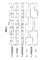
- FIG. 3 is a timing chart showing a setting constitution of a light emission timing.
- a red light is directly obtained by the light emission of an LED (hereinafter referred to as "R-LED”
- a green light is obtained by an LD which emits a blue light (hereinafter referred to as "G-excitation LD”) and a fluorescence wheel in which a ring-like fluorescent layer irradiated with the blue light to emit the green light is formed
- the blue light is obtained directly by the light emission of an LED (hereinafter referred to as "B-LED”), respectively.
- one frame of a color image is constituted of six fields in total of red “R”, green “G”, magenta “Mg”, blue “B”, yellow “Ye” and cyan "Cy”.
- a numeric value "60" (implying an angle of 60°) described for each field indicates that each field period is evenly divided as a center angle corresponding to a rotation angle (one cycle of 360°) of a virtual color wheel.
- the rotation timing of each color filter of the virtual color wheel is beforehand set in the controller circuit as shown in (B) of FIG. 3 .
- a period in which the color filter of each color constituting the color wheel switches at a position of a transmission spot light from the light source is referred to as "spoke period", and it is necessary to set the spoke period.
- this spoke period i.e., a period corresponding to a predetermined angle before and after the switching of the color filter, for example, a center angle of 5° before and after the switching, i.e., 10° in total
- the color image corresponding to the color of the color filter cannot exactly be projected, and each spoke period is allotted to a period to perform gradation emphasis by the complementary color of the adjoining color filters, or the white color.
- FIG. 3 shows a projection sequence of field periods and spoke periods, and the image of each color component corresponding to the sequence is displayed by the micro mirror element. For example, in the spoke period between the "R” field and the “G” field, the gradation emphasis of "Ye” by the addition of the "R” and “G” colors is performed. At this time, as shown in (D) and (E) of FIG.
- the R-LED is turned off at a central timing of the spoke period
- the G-excitation LD is turned on at this timing
- the image corresponding to the color component of the yellow is displayed by the micro mirror element, whereby in this spoke period, it is possible to project the image in which the gradation of the component of the yellow as the additive color of "R" and "G".
- the B-LED is turned off at the central timing of the spoke period
- the R-LED and the G-excitation LD are turned on at the timing
- an image corresponding to a luminance component is displayed by the micro mirror element, whereby in this spoke period, it is possible to project the image in which the gradation of the luminance component of the white "W” as the additive color of "R", "G” and "B” is emphasized.
- the projector is effective for a use application such as presentation where brightness is required for the projected image, while in a use application such as home cinema where not only the brightness but also faithful reproducibility of the color are required, the projector has the defects that the emphasis of the primary colors cannot be performed and that the spoke period cannot effectively be used.
- a projector characterized by comprising: a light source unit (16) which cyclically emits lights of colors by light emission of semiconductor light emission elements (19, 23, 26) in a time sharing manner; a display element (15) which displays an image corresponding to each of color components of lights emitted from the light source unit (16) and forms an optical image by reflected lights or transmitted lights thereof; a projection unit (17, 18) which projects the optical image formed by the display element (15) toward a projection object; a controller (14) which sets a color switch timing to form the image corresponding to each of the color components by the display element; and a projection drive unit (13) which controls a display drive of the display element (15) based on the color switch timing set by the controller (14), wherein: the controller (14) sets a start timing and an end timing of a color transitional period which includes the color switch timing in a center of the color transitional period, and sets one of the start timing and the end timing to coincide with a light source switch timing at which the color
- a projection control method for use in an apparatus including a light source unit (16) which cyclically emits lights of colors by light emission of semiconductor light emission elements (19, 23, 26) in a time sharing manner; a display element (15) which displays an image corresponding to each of color components of lights emitted from the light source unit (16) and forms an optical image by reflected lights or transmitted lights thereof; a projection unit (17, 18) which projects the optical image formed by the display element (15) toward a projection object; a controller (14) which sets a color switch timing to form the image corresponding to each of the color components by the display element; and a projection drive unit (13) which controls a display drive of the display element (15) based on the color switch timing set by the controller (14), the method characterized by comprising: setting a start timing and an end timing of a color transitional period which includes the color switch timing in a center of the color transitional period, and setting one of the start timing and the end timing to coincide with a light source switch timing at which the
- a non-transitory computer-readable storage medium having program code stored thereon for controlling a computer as an apparatus including a light source unit which cyclically emits lights of colors by light emission of semiconductor light emission elements in a time sharing manner; a display element which displays an image corresponding to each of color components of lights emitted from the light source unit and forms an optical image by reflected lights or transmitted lights thereof; a projection unit which projects the optical image formed by the display element toward a projection object; a controller which sets a color switch timing to form the image corresponding to each of the color components by the display element; and a projection drive unit which controls a display drive of the display element based on the color switch timing set by the controller, to carry out the functions of: setting a start timing and an end timing of a color transitional period which includes the color switch timing in a center of the color transitional period, and setting one of the start timing and the end timing to coincide with a light source switch timing at which the color of the light emitted by the
- FIG. 1 is a view showing a schematic functional constitution of a data projector 10 according to the present embodiment.
- An input unit 11 is constituted of, for example, a pin jack (RCA) type video input terminal, a D-sub15 type RGB input terminal, a USB terminal, and a high-definition multimedia interface (HDMI) terminal.
- Image signals of various standards which are input into the input unit 11 are digitized in the input unit 11 as required, and then sent to an image conversion unit 12 via a system bus SB.
- RCA pin jack
- HDMI high-definition multimedia interface
- the image conversion unit 12 is also referred to as the scaler.
- the image conversion unit 12 uniformly converts input image data to the image data of a predetermined format which is suitable for projection, to send the data to a projection drive unit 13.
- the projection drive unit 13 drives based on control of mainly timings by the projection controller 14.
- the projection drive unit 13 drives a micro mirror element 15 which is a spatial optical modulation element to perform display, through higher-speed time sharing drive by multiplying a frame rate of the predetermined format which is, for example, 120 [frames/second], a division number of color components, and a display gradation number.
- the projection controller 14 On the presupposition that the projection controller 14 uses a color wheel, the projection controller 14 beforehand sets, in a color wheel (CW) setting table 14a, respective timings of a color switch timing of each of color filters constituting the color wheel, and sets a start timing and an end timing of a spoke period (or a color transitional period) which includes the above switch timing in a center of the spoke period. On the basis of each set timing, the projection drive unit 13 controls the display drive of the micro mirror element 15 every corresponding color component.
- CW color wheel
- the micro mirror element 15 individually turns on/off micro mirrors arranged in an array, for example, a wide extended graphic array (WXGA) (lateral 1280 pixels x vertical 800 pixels) at each tilt angle with the high speed to display an image, and forms an optical image by reflected light of the element,
- WXGA wide extended graphic array
- a light source unit 16 cyclically emits light-source lights in a time sharing manner by emitting primary color lights of "R", “G” and “B” singly and in combination as a complementary color light.
- the light-source lights from the light source unit 16 are totally reflected by a mirror 17, to irradiate the micro mirror element 15 with the lights.
- the optical image corresponding to each color component of the light-source lights is formed by the reflected light of the micro mirror element 15, and the formed optical image is projected and displayed on a screen (not shown) as a projection object through a projection lens unit 18.
- the light source unit 16 includes an LED 19 which emits the red light (hereinafter referred to as "R-LED 19").
- the red light of "R” emitted by the R-LED 19 is transmitted through a dichroic mirror 20, reflected by a dichroic mirror 21, and then reflected by a mirror 22, to reach the mirror 17.
- the light source unit 16 further includes an LD 23 which emits a blue laser light as an excitation light (hereinafter referred to as "excitation LD 23").
- excitation LD 23 which emits a blue laser light as an excitation light
- the blue laser light of "B” as the excitation light emitted by the excitation LD 23 is transmitted through the dichroic mirror 20, and then the peripheral surface of a fluorescence wheel 24 is irradiated with the light.
- the fluorescence wheel 24 is rotated by a wheel motor (M) 25, and a ring-like fluorescent layer 24g is formed over the whole peripheral surface to be irradiated with the above blue laser light.
- M wheel motor
- the circumference of the fluorescence wheel 24 to be irradiated with the laser light is coated with a fluorescent material, whereby the fluorescent layer 24g is formed.
- a reflecting plate (not shown) is disposed to overlap with the fluorescent layer 24g.
- the green light of "G" is excited as the reflected light.
- This green light is reflected by the dichroic mirror 20, also reflected by the dichroic mirror 21, and then reflected by the mirror 22, to reach the mirror 17.
- the light source unit 16 further includes an LED 26 which emits a blue light (hereinafter referred to as "B-LED 26").
- B-LED 26 a blue light
- the blue light of "B” emitted by the B-LED 26 is transmitted through the dichroic mirror 21, and reflected by the mirror 22, to reach the mirror 17.
- the dichroic mirror 20 transmits the blue light and the red light, while reflecting the green light.
- the dichroic mirror 21 transmits the blue light, while reflecting the green light and the red light.
- a light source drive unit 27 carries out the light emissions of the R-LED 19, the excitation LD 23 and the B-LED 26 and the rotation of the fluorescence wheel 24 by the wheel motor 25, in accordance with timing signals from the projection drive unit 13 and under the control of a CPU 28 described later.
- the CPU 28 is directly connected to a main memory 29 and a program memory 30.
- the main memory 29 is constituted of, for example, an SRAM, and functions as a work memory of the CPU 28.
- the program memory 30 is constituted of an electrically rewritable nonvolatile memory, and stores an operation program to be executed by the CPU 28, various standard data and the like.
- the CPU 28 executes a control operation in the data projector 10 by use of the main memory 29 and the program memory 30.
- the CPU 28 executes various projecting operations in accordance with key operation signals from an operation unit 31.
- the operation unit 31 includes a key operating section disposed in a main body of the data projector 10, and an infrared light receiving section which receives an infrared light from a remote controller (not shown) for exclusive use in the data projector 10. Moreover, the operation unit 31 outputs, directly to the CPU 28, the key operation signal on the basis of a key operated in the key operating section of the main body or the remote controller by a user.
- the CPU 28 is further connected to a voice processing unit 32 via the system bus SB.
- the voice processing unit 32 includes a sound source circuit of a PCM sound source or the like, and the voice processing unit 32 converts voice data given at the projecting operation to analog data, and drives a speaker unit 33 to amplify and emit a sound, or to generate a beep sound or the like as required.
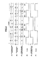
- FIG. 2 is a timing chart showing a setting constitution of a light emission timing according to the present embodiment.
- one frame of a color image is constituted of six fields in total, i.e., red “R”, green “G”, magenta “Mg”, blue “B”, yellow “Ye” and cyan “Cy”.
- a numeric value "60" (implying an angle of 60°) described for each field indicates that each field period is evenly divided as a center angle corresponding to a rotation angle (one cycle of 360°) of a virtual color wheel.
- the rotation timing of each color filter of the virtual color wheel is beforehand set in the color wheel setting table 14a of the projection controller 14 as shown in (B) of FIG. 2 .
- a period in which the color filter of each color constituting the color wheel switches at a position of a transmission spot light from the light source is referred to as "spoke period" (or color switch period), and it is necessary to set the spoke period.
- spoke period or color switch period
- the projection drive unit 13 controls the display drive of the micro mirror element 15 in accordance with the light emission timing of each color component.
- the color filter switching (or color switch timing) is set to form the image corresponding to each of the color components by the display element 15.
- a period corresponding to a predetermined angle before and after the switching of the color filter for example, a center angle of the color wheel which is 5° before and after the switching, i.e., 10° in total is the spoke period.
- the color image corresponding to the color of the color filter cannot exactly be projected, and each spoke period corresponds to a period to perform gradation emphasis by the complementary color of the adjoining color filters, or white.
- a period corresponding to an angle other than 0 degree can be set as the spoke period.
- the timings are set in the color wheel setting table 14a such that one of the start timing and the end timing of the spoke period of each color of the color filter coincides with a switch timing of the color of the light actually emitted by the light source unit 16 as shown in (A) of FIG. 2 .
- the start timing of the first "R” field protrudes as much as 5° to the "Cy” field which is the last field of the previous frame and that the end timing thereof protrudes as much as 5° to the next "G” field, and the "R” field is set, in the color wheel setting table 14a, as a period corresponding to the center angle of the color wheel which is 70° in total.
- the start timing delays as much as 5° described above and that the end timing comes as much as 5° prior to the start of the next "B” field, and the "Mg" field is set, in the color wheel setting table 14a, as a period corresponding to the center angle of the color wheel which is 50° in total.
- the start timing protrudes as much as 5° to the previous "Mg” field as described above and that the end timing protrudes as much as 5° to the next "Ye” field, and the "B" field is set, in the color wheel setting table 14a, as a period corresponding to the center angle of the color wheel which is 70° in total.
- the start timing delays as much as 5° described above and that the end timing comes as much as 5° prior to the start of the next "Cy” field, and the "Ye” field is set, in the color wheel setting table 14a, as a period corresponding to the center angle of the color wheel which is 50° in total.
- the timings are beforehand set in the color wheel setting table 14a of the projection controller 14 such that one of the start timing and the end timing of each spoke period between the fields coincides with a switch timing of the color of the light actually emitted by the light source unit 16.
- each spoke period between the fields is present on one of the previous field side and the next field side of the original field switch timing.
- a first spoke period "SP1" positioned between the "R” field positioned first in the one frame and the next "G” field is positioned in a leading portion of the second "G” field at an actual projection timing.
- a second spoke period "SP2" positioned between the second "G” field and the third "Mg” field is positioned in a leading portion of the third "Mg” field at the actual projection timing.
- a third spoke period "SP3" positioned between the third "Mg” field and the fourth "B” field is positioned in an ending portion of the third "Mg” field at the actual projection timing.
- a fourth spoke period "SP4" positioned between the fourth "B” field and the fifth "Ye” field is positioned in a leading portion of the fifth "Ye” field at the actual projection timing.
- a fifth spoke period "SP5" positioned between the fifth "Ye” field and the sixth "Cy” field is positioned in an ending portion of the fifth "Ye” field at the actual projection timing.
- a sixth spoke period "SP6" positioned between the sixth "Cy” field and the leading "R” field of the next frame is positioned in an ending portion of the sixth "Cy” field at the actual projection timing.
- the optical image corresponding to the color component of "R” can be projected by fully using a projection period of 60° in the previous "R” field, and further in the subsequent "G” field, the optical image corresponding to the color component of "G” can be projected by fully using the projection period of 60°.
- the optical image corresponding to the color component of "Mg” can be projected by fully using a projection period of 60° in the "Mg” field, and further in the subsequent "B” field, the optical image corresponding to the color component of "B” can be projected by fully using the projection period of 60°.
- the optical image corresponding to the color component of Ye can be projected by fully using a projection period of 60° in the "Ye” field.
- the optical image corresponding to the color component of "Cy” can be projected by fully using a projection period of 60° in the "Cy” field, in the setting in which the image corresponding to the color component of "Cy” is displayed by the micro mirror element 15 in the sixth spoke period "SP6" positioned in the ending portion of the field.
- the B-LED 26 which emits the blue light of "B” are driven to be on and off synchronously with the switch timing of the frame constitution shown in (A) of FIG. 2 , as shown in (D), (E) and (F) of FIG. 2 .
- the light-source lights including a primary color light by the single color or a complementary color light obtained by mixing two color lights using an additive light is possible, and it is not necessary to perform light emission drive or the like in a partially repeated manner between the adjacent fields in consideration of the spoke period, which further facilitates the control sequence.
- the field periods of the primary colors in which each of the primary colors of "R", "G” and “B” is emitted singly, are included, and hence it is possible to securely enhance the expressive power especially in a projection mode for use in a home theater or the like in which the expressive power of chroma is more required than brightness.
- the fluorescence wheel 24 provided with the ring-like fluorescent layer 24g is rotated and driven by the wheel motor 25, and the blue light as the excitation light is emitted by the excitation LD 23 to obtain the green light by the reflected light of the LD.
- the constitution of the B-LED 26 in the light source unit 16 is omitted, the fluorescent layer 24g is not formed but a transmission portion to transmit the blue light is formed in part of the peripheral surface of the fluorescence wheel 24, and the transmitted blue light is used directly as the light-source light.
- This constitution can be considered as a constitution in which the number of the components of the semiconductor light emission element constituting the light source unit 16 is further decreased.
- the light source unit 16 includes the R-LED 19 which emits the red light, the excitation LD 23 which emits the blue light as the excitation light to excite the green light, and the B-LED 26 which emits the blue light.
- the present invention is not limited to this embodiment, and there is similarly considered a constitution using a semiconductor light emission element or the like in which the additive color of the primary colors is not used but the complementary color light is emitted directly in the single color.
Landscapes
- Engineering & Computer Science (AREA)
- Multimedia (AREA)
- Signal Processing (AREA)
- Physics & Mathematics (AREA)
- Optics & Photonics (AREA)
- General Physics & Mathematics (AREA)
- Projection Apparatus (AREA)
- Video Image Reproduction Devices For Color Tv Systems (AREA)
Applications Claiming Priority (1)
| Application Number | Priority Date | Filing Date | Title |
|---|---|---|---|
| JP2011228094A JP5494610B2 (ja) | 2011-10-17 | 2011-10-17 | 投影装置、投影制御方法及びプログラム |
Publications (3)
| Publication Number | Publication Date |
|---|---|
| EP2584783A2 true EP2584783A2 (de) | 2013-04-24 |
| EP2584783A3 EP2584783A3 (de) | 2017-06-28 |
| EP2584783B1 EP2584783B1 (de) | 2022-03-09 |
Family
ID=47022572
Family Applications (1)
| Application Number | Title | Priority Date | Filing Date |
|---|---|---|---|
| EP12188627.9A Active EP2584783B1 (de) | 2011-10-17 | 2012-10-16 | Projektor, Projektionssteuerungsverfahren und Speichermedium mit Programm |
Country Status (4)
| Country | Link |
|---|---|
| US (1) | US20130094001A1 (de) |
| EP (1) | EP2584783B1 (de) |
| JP (1) | JP5494610B2 (de) |
| CN (1) | CN103048856B (de) |
Families Citing this family (12)
| Publication number | Priority date | Publication date | Assignee | Title |
|---|---|---|---|---|
| CN103728824B (zh) * | 2013-12-30 | 2015-09-02 | 苏州佳世达光电有限公司 | 光源系统 |
| US20150215569A1 (en) * | 2014-01-29 | 2015-07-30 | Wavien, Inc. | Projector with light source including laser, phosphor, and led |
| CN104360487B (zh) * | 2014-12-12 | 2016-10-05 | 合肥鑫晟光电科技有限公司 | 一种激光投影显示方法及装置 |
| JP6536874B2 (ja) * | 2014-12-19 | 2019-07-03 | カシオ計算機株式会社 | 投影装置 |
| JP6565846B2 (ja) * | 2016-09-16 | 2019-08-28 | カシオ計算機株式会社 | 光源装置及び投影装置 |
| CN111240140B (zh) | 2018-11-29 | 2022-08-30 | 青岛海信激光显示股份有限公司 | 光阀驱动控制方法、装置及投影设备 |
| JP7145448B2 (ja) * | 2018-12-10 | 2022-10-03 | パナソニックIpマネジメント株式会社 | 投射型映像表示装置 |
| CN109788264B (zh) * | 2018-12-20 | 2021-04-20 | 歌尔光学科技有限公司 | 帧同步信号生成方法及投影设备 |
| JP6970896B2 (ja) | 2019-04-10 | 2021-11-24 | カシオ計算機株式会社 | 投影装置、投影制御装置及びプログラム |
| JP7303990B2 (ja) * | 2019-04-10 | 2023-07-06 | カシオ計算機株式会社 | 投影装置、投影制御装置及びプログラム |
| JP6960093B2 (ja) | 2019-04-10 | 2021-11-05 | カシオ計算機株式会社 | 投影装置、投影制御装置及びプログラム |
| CN213423690U (zh) * | 2020-10-21 | 2021-06-11 | 中强光电股份有限公司 | 照明系统及投影装置 |
Citations (1)
| Publication number | Priority date | Publication date | Assignee | Title |
|---|---|---|---|---|
| JP2011095388A (ja) | 2009-10-28 | 2011-05-12 | Casio Computer Co Ltd | 光源ユニット及びプロジェクタ |
Family Cites Families (23)
| Publication number | Priority date | Publication date | Assignee | Title |
|---|---|---|---|---|
| JPH11264953A (ja) * | 1998-03-17 | 1999-09-28 | Minolta Co Ltd | カラー投影装置 |
| JP4237090B2 (ja) * | 2004-04-07 | 2009-03-11 | Necディスプレイソリューションズ株式会社 | カラープロジェクタ及びその同期調整方法 |
| KR100565810B1 (ko) * | 2004-06-16 | 2006-03-29 | 삼성전자주식회사 | 색신호 처리장치 및 방법 |
| JP4285428B2 (ja) * | 2005-03-25 | 2009-06-24 | カシオ計算機株式会社 | 投影装置 |
| US7384150B2 (en) * | 2005-05-27 | 2008-06-10 | 3M Innovative Properties Company | Light emitting diode (LED) illumination control system and method |
| JP2008261998A (ja) * | 2007-04-11 | 2008-10-30 | Olympus Corp | 光源装置およびプロジェクタ |
| JP2009092745A (ja) * | 2007-10-04 | 2009-04-30 | Necディスプレイソリューションズ株式会社 | 映像表示装置及びその光源駆動方法 |
| JP4692623B2 (ja) * | 2008-12-17 | 2011-06-01 | カシオ計算機株式会社 | 光源装置及び光源制御方法 |
| JP4900736B2 (ja) * | 2009-03-31 | 2012-03-21 | カシオ計算機株式会社 | 光源装置及びプロジェクタ |
| TWI392954B (zh) * | 2009-05-11 | 2013-04-11 | Coretronic Corp | 照明系統及照明控制方法 |
| JP4883376B2 (ja) * | 2009-06-30 | 2012-02-22 | カシオ計算機株式会社 | 蛍光体基板及び光源装置、プロジェクタ |
| JP4742349B2 (ja) * | 2009-06-30 | 2011-08-10 | カシオ計算機株式会社 | 光源装置及びプロジェクタ |
| JP4711021B2 (ja) * | 2009-06-30 | 2011-06-29 | カシオ計算機株式会社 | 投影装置 |
| JP4711156B2 (ja) * | 2009-06-30 | 2011-06-29 | カシオ計算機株式会社 | 光源装置及びプロジェクタ |
| JP5412996B2 (ja) * | 2009-06-30 | 2014-02-12 | カシオ計算機株式会社 | 光源装置、投影装置及び投影方法 |
| JP5625287B2 (ja) * | 2009-08-21 | 2014-11-19 | カシオ計算機株式会社 | 光源装置、投影装置、投影方法及びプログラム |
| JP5796272B2 (ja) * | 2009-09-28 | 2015-10-21 | カシオ計算機株式会社 | 光源装置、投影装置及び投影方法 |
| JP2011075919A (ja) * | 2009-09-30 | 2011-04-14 | Casio Computer Co Ltd | 光源装置、投影装置及び投影方法 |
| JP5500341B2 (ja) * | 2009-10-28 | 2014-05-21 | カシオ計算機株式会社 | 光源ユニット及びプロジェクタ |
| KR101202724B1 (ko) * | 2009-10-28 | 2012-11-19 | 가시오게산키 가부시키가이샤 | 광원 유닛 및 프로젝터 |
| JP5491888B2 (ja) * | 2010-02-05 | 2014-05-14 | 日立コンシューマエレクトロニクス株式会社 | 投写型表示装置 |
| JP5494053B2 (ja) * | 2010-03-16 | 2014-05-14 | セイコーエプソン株式会社 | プロジェクター |
| US8616705B2 (en) * | 2011-11-04 | 2013-12-31 | Appotronics (China) Corporation | Light source device and projection display method |
-
2011
- 2011-10-17 JP JP2011228094A patent/JP5494610B2/ja active Active
-
2012
- 2012-10-15 US US13/651,570 patent/US20130094001A1/en not_active Abandoned
- 2012-10-16 EP EP12188627.9A patent/EP2584783B1/de active Active
- 2012-10-17 CN CN201210394264.0A patent/CN103048856B/zh active Active
Patent Citations (1)
| Publication number | Priority date | Publication date | Assignee | Title |
|---|---|---|---|---|
| JP2011095388A (ja) | 2009-10-28 | 2011-05-12 | Casio Computer Co Ltd | 光源ユニット及びプロジェクタ |
Also Published As
| Publication number | Publication date |
|---|---|
| JP5494610B2 (ja) | 2014-05-21 |
| EP2584783A3 (de) | 2017-06-28 |
| CN103048856B (zh) | 2016-01-06 |
| US20130094001A1 (en) | 2013-04-18 |
| JP2013088574A (ja) | 2013-05-13 |
| EP2584783B1 (de) | 2022-03-09 |
| CN103048856A (zh) | 2013-04-17 |
Similar Documents
| Publication | Publication Date | Title |
|---|---|---|
| EP2584783A2 (de) | Projektor, Projektionssteuerungsverfahren und Speichermedium mit Programm | |
| US8403493B2 (en) | Projection apparatus and projection method for controlling emission of plural color light sources having different luminous efficiencies | |
| TWI439726B (zh) | 光源裝置、投影裝置及投影方法 | |
| JP4900428B2 (ja) | 投影装置及び投影方法 | |
| US8272745B2 (en) | Light source device, projection apparatus, and projection method | |
| US8444276B2 (en) | Light source device, projection apparatus including the light source device, and projection method | |
| KR101643032B1 (ko) | 혼색 기간의 단축에 의해 전력 소비의 저감화를 실현하는 투영 장치, 투영 방법 및 프로그램을 기록한 기록매체 | |
| US10861364B2 (en) | Projector and projection method | |
| JP2012128438A (ja) | 光源装置、投影装置及び投影方法 | |
| JP2011075673A (ja) | 光源装置、投影装置及び投影方法 | |
| JP6135037B2 (ja) | 投影装置、投影方法及びプログラム | |
| JP5445575B2 (ja) | 投影装置及び投影方法 | |
| JP5716802B2 (ja) | 投影装置、投影方法及びプログラム | |
| JP5375115B2 (ja) | 投影装置、投影方法及びプログラム | |
| CN110018606B (zh) | 光源装置以及投影装置 | |
| JP2014160247A (ja) | 投影装置、投影制御方法及びプログラム | |
| JP2017182071A (ja) | 投影装置、投影方法及びプログラム |
Legal Events
| Date | Code | Title | Description |
|---|---|---|---|
| PUAI | Public reference made under article 153(3) epc to a published international application that has entered the european phase |
Free format text: ORIGINAL CODE: 0009012 |
|
| 17P | Request for examination filed |
Effective date: 20121016 |
|
| AK | Designated contracting states |
Kind code of ref document: A2 Designated state(s): AL AT BE BG CH CY CZ DE DK EE ES FI FR GB GR HR HU IE IS IT LI LT LU LV MC MK MT NL NO PL PT RO RS SE SI SK SM TR |
|
| AX | Request for extension of the european patent |
Extension state: BA ME |
|
| PUAL | Search report despatched |
Free format text: ORIGINAL CODE: 0009013 |
|
| AK | Designated contracting states |
Kind code of ref document: A3 Designated state(s): AL AT BE BG CH CY CZ DE DK EE ES FI FR GB GR HR HU IE IS IT LI LT LU LV MC MK MT NL NO PL PT RO RS SE SI SK SM TR |
|
| AX | Request for extension of the european patent |
Extension state: BA ME |
|
| RIC1 | Information provided on ipc code assigned before grant |
Ipc: H04N 9/31 20060101AFI20170523BHEP |
|
| STAA | Information on the status of an ep patent application or granted ep patent |
Free format text: STATUS: EXAMINATION IS IN PROGRESS |
|
| 17Q | First examination report despatched |
Effective date: 20200129 |
|
| GRAJ | Information related to disapproval of communication of intention to grant by the applicant or resumption of examination proceedings by the epo deleted |
Free format text: ORIGINAL CODE: EPIDOSDIGR1 |
|
| GRAP | Despatch of communication of intention to grant a patent |
Free format text: ORIGINAL CODE: EPIDOSNIGR1 |
|
| GRAP | Despatch of communication of intention to grant a patent |
Free format text: ORIGINAL CODE: EPIDOSNIGR1 |
|
| STAA | Information on the status of an ep patent application or granted ep patent |
Free format text: STATUS: GRANT OF PATENT IS INTENDED |
|
| INTC | Intention to grant announced (deleted) | ||
| INTG | Intention to grant announced |
Effective date: 20211115 |
|
| GRAS | Grant fee paid |
Free format text: ORIGINAL CODE: EPIDOSNIGR3 |
|
| GRAA | (expected) grant |
Free format text: ORIGINAL CODE: 0009210 |
|
| STAA | Information on the status of an ep patent application or granted ep patent |
Free format text: STATUS: THE PATENT HAS BEEN GRANTED |
|
| AK | Designated contracting states |
Kind code of ref document: B1 Designated state(s): AL AT BE BG CH CY CZ DE DK EE ES FI FR GB GR HR HU IE IS IT LI LT LU LV MC MK MT NL NO PL PT RO RS SE SI SK SM TR |
|
| REG | Reference to a national code |
Ref country code: GB Ref legal event code: FG4D |
|
| REG | Reference to a national code |
Ref country code: CH Ref legal event code: EP Ref country code: AT Ref legal event code: REF Ref document number: 1475112 Country of ref document: AT Kind code of ref document: T Effective date: 20220315 |
|
| REG | Reference to a national code |
Ref country code: DE Ref legal event code: R096 Ref document number: 602012077801 Country of ref document: DE |
|
| REG | Reference to a national code |
Ref country code: IE Ref legal event code: FG4D |
|
| REG | Reference to a national code |
Ref country code: LT Ref legal event code: MG9D |
|
| REG | Reference to a national code |
Ref country code: NL Ref legal event code: MP Effective date: 20220309 |
|
| PG25 | Lapsed in a contracting state [announced via postgrant information from national office to epo] |
Ref country code: SE Free format text: LAPSE BECAUSE OF FAILURE TO SUBMIT A TRANSLATION OF THE DESCRIPTION OR TO PAY THE FEE WITHIN THE PRESCRIBED TIME-LIMIT Effective date: 20220309 Ref country code: RS Free format text: LAPSE BECAUSE OF FAILURE TO SUBMIT A TRANSLATION OF THE DESCRIPTION OR TO PAY THE FEE WITHIN THE PRESCRIBED TIME-LIMIT Effective date: 20220309 Ref country code: NO Free format text: LAPSE BECAUSE OF FAILURE TO SUBMIT A TRANSLATION OF THE DESCRIPTION OR TO PAY THE FEE WITHIN THE PRESCRIBED TIME-LIMIT Effective date: 20220609 Ref country code: LT Free format text: LAPSE BECAUSE OF FAILURE TO SUBMIT A TRANSLATION OF THE DESCRIPTION OR TO PAY THE FEE WITHIN THE PRESCRIBED TIME-LIMIT Effective date: 20220309 Ref country code: HR Free format text: LAPSE BECAUSE OF FAILURE TO SUBMIT A TRANSLATION OF THE DESCRIPTION OR TO PAY THE FEE WITHIN THE PRESCRIBED TIME-LIMIT Effective date: 20220309 Ref country code: BG Free format text: LAPSE BECAUSE OF FAILURE TO SUBMIT A TRANSLATION OF THE DESCRIPTION OR TO PAY THE FEE WITHIN THE PRESCRIBED TIME-LIMIT Effective date: 20220609 |
|
| REG | Reference to a national code |
Ref country code: AT Ref legal event code: MK05 Ref document number: 1475112 Country of ref document: AT Kind code of ref document: T Effective date: 20220309 |
|
| PG25 | Lapsed in a contracting state [announced via postgrant information from national office to epo] |
Ref country code: LV Free format text: LAPSE BECAUSE OF FAILURE TO SUBMIT A TRANSLATION OF THE DESCRIPTION OR TO PAY THE FEE WITHIN THE PRESCRIBED TIME-LIMIT Effective date: 20220309 Ref country code: GR Free format text: LAPSE BECAUSE OF FAILURE TO SUBMIT A TRANSLATION OF THE DESCRIPTION OR TO PAY THE FEE WITHIN THE PRESCRIBED TIME-LIMIT Effective date: 20220610 Ref country code: FI Free format text: LAPSE BECAUSE OF FAILURE TO SUBMIT A TRANSLATION OF THE DESCRIPTION OR TO PAY THE FEE WITHIN THE PRESCRIBED TIME-LIMIT Effective date: 20220309 |
|
| PG25 | Lapsed in a contracting state [announced via postgrant information from national office to epo] |
Ref country code: NL Free format text: LAPSE BECAUSE OF FAILURE TO SUBMIT A TRANSLATION OF THE DESCRIPTION OR TO PAY THE FEE WITHIN THE PRESCRIBED TIME-LIMIT Effective date: 20220309 |
|
| PG25 | Lapsed in a contracting state [announced via postgrant information from national office to epo] |
Ref country code: SM Free format text: LAPSE BECAUSE OF FAILURE TO SUBMIT A TRANSLATION OF THE DESCRIPTION OR TO PAY THE FEE WITHIN THE PRESCRIBED TIME-LIMIT Effective date: 20220309 Ref country code: SK Free format text: LAPSE BECAUSE OF FAILURE TO SUBMIT A TRANSLATION OF THE DESCRIPTION OR TO PAY THE FEE WITHIN THE PRESCRIBED TIME-LIMIT Effective date: 20220309 Ref country code: RO Free format text: LAPSE BECAUSE OF FAILURE TO SUBMIT A TRANSLATION OF THE DESCRIPTION OR TO PAY THE FEE WITHIN THE PRESCRIBED TIME-LIMIT Effective date: 20220309 Ref country code: PT Free format text: LAPSE BECAUSE OF FAILURE TO SUBMIT A TRANSLATION OF THE DESCRIPTION OR TO PAY THE FEE WITHIN THE PRESCRIBED TIME-LIMIT Effective date: 20220711 Ref country code: ES Free format text: LAPSE BECAUSE OF FAILURE TO SUBMIT A TRANSLATION OF THE DESCRIPTION OR TO PAY THE FEE WITHIN THE PRESCRIBED TIME-LIMIT Effective date: 20220309 Ref country code: EE Free format text: LAPSE BECAUSE OF FAILURE TO SUBMIT A TRANSLATION OF THE DESCRIPTION OR TO PAY THE FEE WITHIN THE PRESCRIBED TIME-LIMIT Effective date: 20220309 Ref country code: CZ Free format text: LAPSE BECAUSE OF FAILURE TO SUBMIT A TRANSLATION OF THE DESCRIPTION OR TO PAY THE FEE WITHIN THE PRESCRIBED TIME-LIMIT Effective date: 20220309 Ref country code: AT Free format text: LAPSE BECAUSE OF FAILURE TO SUBMIT A TRANSLATION OF THE DESCRIPTION OR TO PAY THE FEE WITHIN THE PRESCRIBED TIME-LIMIT Effective date: 20220309 |
|
| PG25 | Lapsed in a contracting state [announced via postgrant information from national office to epo] |
Ref country code: PL Free format text: LAPSE BECAUSE OF FAILURE TO SUBMIT A TRANSLATION OF THE DESCRIPTION OR TO PAY THE FEE WITHIN THE PRESCRIBED TIME-LIMIT Effective date: 20220309 Ref country code: IS Free format text: LAPSE BECAUSE OF FAILURE TO SUBMIT A TRANSLATION OF THE DESCRIPTION OR TO PAY THE FEE WITHIN THE PRESCRIBED TIME-LIMIT Effective date: 20220709 Ref country code: AL Free format text: LAPSE BECAUSE OF FAILURE TO SUBMIT A TRANSLATION OF THE DESCRIPTION OR TO PAY THE FEE WITHIN THE PRESCRIBED TIME-LIMIT Effective date: 20220309 |
|
| REG | Reference to a national code |
Ref country code: DE Ref legal event code: R097 Ref document number: 602012077801 Country of ref document: DE |
|
| PLBE | No opposition filed within time limit |
Free format text: ORIGINAL CODE: 0009261 |
|
| STAA | Information on the status of an ep patent application or granted ep patent |
Free format text: STATUS: NO OPPOSITION FILED WITHIN TIME LIMIT |
|
| PG25 | Lapsed in a contracting state [announced via postgrant information from national office to epo] |
Ref country code: DK Free format text: LAPSE BECAUSE OF FAILURE TO SUBMIT A TRANSLATION OF THE DESCRIPTION OR TO PAY THE FEE WITHIN THE PRESCRIBED TIME-LIMIT Effective date: 20220309 |
|
| 26N | No opposition filed |
Effective date: 20221212 |
|
| PG25 | Lapsed in a contracting state [announced via postgrant information from national office to epo] |
Ref country code: SI Free format text: LAPSE BECAUSE OF FAILURE TO SUBMIT A TRANSLATION OF THE DESCRIPTION OR TO PAY THE FEE WITHIN THE PRESCRIBED TIME-LIMIT Effective date: 20220309 |
|
| PG25 | Lapsed in a contracting state [announced via postgrant information from national office to epo] |
Ref country code: MC Free format text: LAPSE BECAUSE OF FAILURE TO SUBMIT A TRANSLATION OF THE DESCRIPTION OR TO PAY THE FEE WITHIN THE PRESCRIBED TIME-LIMIT Effective date: 20220309 |
|
| REG | Reference to a national code |
Ref country code: CH Ref legal event code: PL |
|
| REG | Reference to a national code |
Ref country code: BE Ref legal event code: MM Effective date: 20221031 |
|
| PG25 | Lapsed in a contracting state [announced via postgrant information from national office to epo] |
Ref country code: LU Free format text: LAPSE BECAUSE OF NON-PAYMENT OF DUE FEES Effective date: 20221016 |
|
| PG25 | Lapsed in a contracting state [announced via postgrant information from national office to epo] |
Ref country code: LI Free format text: LAPSE BECAUSE OF NON-PAYMENT OF DUE FEES Effective date: 20221031 Ref country code: IT Free format text: LAPSE BECAUSE OF FAILURE TO SUBMIT A TRANSLATION OF THE DESCRIPTION OR TO PAY THE FEE WITHIN THE PRESCRIBED TIME-LIMIT Effective date: 20220309 Ref country code: CH Free format text: LAPSE BECAUSE OF NON-PAYMENT OF DUE FEES Effective date: 20221031 |
|
| PG25 | Lapsed in a contracting state [announced via postgrant information from national office to epo] |
Ref country code: BE Free format text: LAPSE BECAUSE OF NON-PAYMENT OF DUE FEES Effective date: 20221031 |
|
| PG25 | Lapsed in a contracting state [announced via postgrant information from national office to epo] |
Ref country code: IE Free format text: LAPSE BECAUSE OF NON-PAYMENT OF DUE FEES Effective date: 20221016 |
|
| PG25 | Lapsed in a contracting state [announced via postgrant information from national office to epo] |
Ref country code: HU Free format text: LAPSE BECAUSE OF FAILURE TO SUBMIT A TRANSLATION OF THE DESCRIPTION OR TO PAY THE FEE WITHIN THE PRESCRIBED TIME-LIMIT; INVALID AB INITIO Effective date: 20121016 |
|
| PG25 | Lapsed in a contracting state [announced via postgrant information from national office to epo] |
Ref country code: CY Free format text: LAPSE BECAUSE OF FAILURE TO SUBMIT A TRANSLATION OF THE DESCRIPTION OR TO PAY THE FEE WITHIN THE PRESCRIBED TIME-LIMIT Effective date: 20220309 |
|
| PG25 | Lapsed in a contracting state [announced via postgrant information from national office to epo] |
Ref country code: MK Free format text: LAPSE BECAUSE OF FAILURE TO SUBMIT A TRANSLATION OF THE DESCRIPTION OR TO PAY THE FEE WITHIN THE PRESCRIBED TIME-LIMIT Effective date: 20220309 |
|
| PG25 | Lapsed in a contracting state [announced via postgrant information from national office to epo] |
Ref country code: TR Free format text: LAPSE BECAUSE OF FAILURE TO SUBMIT A TRANSLATION OF THE DESCRIPTION OR TO PAY THE FEE WITHIN THE PRESCRIBED TIME-LIMIT Effective date: 20220309 |
|
| PG25 | Lapsed in a contracting state [announced via postgrant information from national office to epo] |
Ref country code: MT Free format text: LAPSE BECAUSE OF FAILURE TO SUBMIT A TRANSLATION OF THE DESCRIPTION OR TO PAY THE FEE WITHIN THE PRESCRIBED TIME-LIMIT Effective date: 20220309 |
|
| PGFP | Annual fee paid to national office [announced via postgrant information from national office to epo] |
Ref country code: GB Payment date: 20250828 Year of fee payment: 14 |
|
| PGFP | Annual fee paid to national office [announced via postgrant information from national office to epo] |
Ref country code: FR Payment date: 20250908 Year of fee payment: 14 |
|
| PGFP | Annual fee paid to national office [announced via postgrant information from national office to epo] |
Ref country code: DE Payment date: 20250902 Year of fee payment: 14 |