EP1970329A1 - Artikelfördervorrichtung - Google Patents
Artikelfördervorrichtung Download PDFInfo
- Publication number
- EP1970329A1 EP1970329A1 EP08250638A EP08250638A EP1970329A1 EP 1970329 A1 EP1970329 A1 EP 1970329A1 EP 08250638 A EP08250638 A EP 08250638A EP 08250638 A EP08250638 A EP 08250638A EP 1970329 A1 EP1970329 A1 EP 1970329A1
- Authority
- EP
- European Patent Office
- Prior art keywords
- grippers
- rotary wheel
- side rotary
- upstream side
- downstream side
- Prior art date
- Legal status (The legal status is an assumption and is not a legal conclusion. Google has not performed a legal analysis and makes no representation as to the accuracy of the status listed.)
- Granted
Links
Images


Classifications
-
- B—PERFORMING OPERATIONS; TRANSPORTING
- B65—CONVEYING; PACKING; STORING; HANDLING THIN OR FILAMENTARY MATERIAL
- B65G—TRANSPORT OR STORAGE DEVICES, e.g. CONVEYORS FOR LOADING OR TIPPING, SHOP CONVEYOR SYSTEMS OR PNEUMATIC TUBE CONVEYORS
- B65G47/00—Article or material-handling devices associated with conveyors; Methods employing such devices
- B65G47/74—Feeding, transfer, or discharging devices of particular kinds or types
- B65G47/84—Star-shaped wheels or devices having endless travelling belts or chains, the wheels or devices being equipped with article-engaging elements
- B65G47/846—Star-shaped wheels or wheels equipped with article-engaging elements
- B65G47/847—Star-shaped wheels or wheels equipped with article-engaging elements the article-engaging elements being grippers
-
- B—PERFORMING OPERATIONS; TRANSPORTING
- B65—CONVEYING; PACKING; STORING; HANDLING THIN OR FILAMENTARY MATERIAL
- B65G—TRANSPORT OR STORAGE DEVICES, e.g. CONVEYORS FOR LOADING OR TIPPING, SHOP CONVEYOR SYSTEMS OR PNEUMATIC TUBE CONVEYORS
- B65G29/00—Rotary conveyors, e.g. rotating discs, arms, star-wheels or cones
-
- B—PERFORMING OPERATIONS; TRANSPORTING
- B67—OPENING, CLOSING OR CLEANING BOTTLES, JARS OR SIMILAR CONTAINERS; LIQUID HANDLING
- B67C—CLEANING, FILLING WITH LIQUIDS OR SEMILIQUIDS, OR EMPTYING, OF BOTTLES, JARS, CANS, CASKS, BARRELS, OR SIMILAR CONTAINERS, NOT OTHERWISE PROVIDED FOR; FUNNELS
- B67C3/00—Bottling liquids or semiliquids; Filling jars or cans with liquids or semiliquids using bottling or like apparatus; Filling casks or barrels with liquids or semiliquids
- B67C3/02—Bottling liquids or semiliquids; Filling jars or cans with liquids or semiliquids using bottling or like apparatus
- B67C3/22—Details
- B67C3/24—Devices for supporting or handling bottles
- B67C3/242—Devices for supporting or handling bottles engaging with bottle necks
-
- B—PERFORMING OPERATIONS; TRANSPORTING
- B67—OPENING, CLOSING OR CLEANING BOTTLES, JARS OR SIMILAR CONTAINERS; LIQUID HANDLING
- B67C—CLEANING, FILLING WITH LIQUIDS OR SEMILIQUIDS, OR EMPTYING, OF BOTTLES, JARS, CANS, CASKS, BARRELS, OR SIMILAR CONTAINERS, NOT OTHERWISE PROVIDED FOR; FUNNELS
- B67C7/00—Concurrent cleaning, filling, and closing of bottles; Processes or devices for at least two of these operations
- B67C7/0006—Conveying; Synchronising
- B67C7/004—Conveying; Synchronising the containers travelling along a circular path
- B67C7/0046—Infeed and outfeed devices
- B67C7/0053—Infeed and outfeed devices using grippers
-
- B—PERFORMING OPERATIONS; TRANSPORTING
- B65—CONVEYING; PACKING; STORING; HANDLING THIN OR FILAMENTARY MATERIAL
- B65G—TRANSPORT OR STORAGE DEVICES, e.g. CONVEYORS FOR LOADING OR TIPPING, SHOP CONVEYOR SYSTEMS OR PNEUMATIC TUBE CONVEYORS
- B65G2201/00—Indexing codes relating to handling devices, e.g. conveyors, characterised by the type of product or load being conveyed or handled
- B65G2201/02—Articles
- B65G2201/0235—Containers
- B65G2201/0244—Bottles
- B65G2201/0247—Suspended bottles
Definitions
- the present invention relates to an article conveying device, and particularly relates to an article conveying device which delivers articles to grippers of a rotary wheel at a downstream side from grippers of a rotary wheel at an upstream side in a delivery position in which the rotary wheels are adjacent to each other.
- Patent Documents 1 and 2 Conventionally, in a beverage manufacturing line which carries out molding of, for example, plastic bottles as articles to filling of beverage, a molding device for molding the plastic bottles and a filling device for filling beverage or the like into the plastic bottles are included, and the molding device and filling device are provided with an article conveying device for conveying the plastic bottles (Patent Documents 1 and 2).
- a conveying device 3 for conveying plastic bottles is provided between the molding device and the filling device, and as the article conveying device of Patent Document 2, a star-shaped conveying wheel 6 and a star-shaped conveying wheel 7 which are adjacent to each other are provided in the boundary of the molding device and the filling device.
- the star-shaped conveying wheels 6 and 7 of Patent Document 2 respectively include a plurality of grippers, so that plastic bottles are delivered to the grippers of the star-shaped conveying wheel 7 from the grippers of the star-shaped conveying wheel 6 in the delivery position in which the star-shaped conveying wheels 6 and 7 are adjacent to each other.
- the present invention provides an article conveying device in which even if one rotary wheel abnormally stops, the other rotary wheel can be continuously operated, without increasing the size of equipment.
- a first aspect of the present invention is, in an article conveying device in which a plurality of rotary wheels each provided with a plurality of grippers gripping articles equidistantly in a circumferential direction are disposed and in each delivery position in which these rotary wheels are adjacent to each other, articles are delivered from grippers of an upstream side rotary wheel to grippers of a downstream side rotary wheel, characterized by including retreating means switching the grippers provided at the downstream side rotary wheel between a use state in which the grippers receive articles from the upstream side rotary wheel and a retreat state in which the grippers do not interfere with the articles held by the upstream side rotary wheel, and control means controlling the retreating means, and characterized in that when the aforesaid upstream side rotary wheel abnormally stops, the aforesaid control means controls the aforesaid retreating means to switch at least the grippers of the downstream side rotary wheel, which are located in said delivery position, from the use state to the retreat state to prevent the grippers
- a second aspect of the present invention is, in an article conveying device in which a plurality of rotary wheels each provided with a plurality of grippers gripping articles equidistantly in a circumferential direction are disposed and in each delivery position in which these rotary wheels are adjacent to each another, articles are delivered from grippers of an upstream side rotary wheel to grippers of a downstream side rotary wheel, characterized by including retreating means switching the grippers provided at the upstream side rotary wheel between a use state in which the grippers deliver articles to the downstream side rotary wheel and a retreat state in which the grippers do not interfere with the articles held by the downstream side rotary wheel, and control means controlling the retreating means, and characterized in that when the aforesaid upstream side rotary wheel abnormally stops, the aforesaid control means controls the aforesaid retreating means to switch at least the grippers of the upstream side rotary wheel, which are located in the aforesaid delivery position, from the use state to the retreat state
- a third aspect of the present invention is, in an article conveying device in which a plurality of rotary wheels each provided with a plurality of grippers gripping articles equidistantly in a circumferential direction are disposed and in each delivery position in which these rotary wheels are adjacent to each other, articles are delivered from grippers of an upstream side rotary wheel to grippers of a downstream side rotary wheel, characterized by including retreating means switching the grippers provided at the downstream side rotary wheel between a use state in which the grippers receive articles from the upstream side rotary wheel and a retreat state in which the grippers do not interfere with the articles held by the upstream side rotary wheel, and control means controlling the retreating means, and characterized in that when the aforesaid downstream side rotary wheel abnormally stops, the aforesaid control means controls the aforesaid retreating means to switch at least the grippers of the downstream side rotary wheel, which are located in the aforesaid delivery position, from the use state to the retreat state to
- a fourth aspect of the present invention is, in an article conveying device in which a plurality of rotary wheels each provided with a plurality of grippers gripping articles equidistantly in a circumferential direction are disposed and in each delivery position in which these rotary wheels are adjacent to each another, articles are delivered from grippers of an upstream side rotary wheel to grippers of a downstream side rotary wheel, characterized by including retreating means switching the grippers provided at the upstream side rotary wheels between a use state in which the grippers deliver articles to the downstream side rotary wheel and a retreat state in which the grippers do not interfere with the articles held by the downstream side rotary wheel, and control means controlling the retreating means, and characterized in that when the aforesaid downstream side rotary wheel abnormally stops, the aforesaid control means controls the aforesaid retreating means to switch at least the grippers of the upstream side rotary wheel which are located in the aforesaid delivery position from the use state to the retreat state to prevent the grippers
- the upstream side rotary wheel and the downstream side rotary wheel are provided in the positions adjacent to each other, and therefore, the conveying device 3 as in the Patent Document 1 is not required, and the equipment can be downsized.
- the grippers of the downstream side rotary wheel are switched to the retreat state from the use state by the retreating means, and the grippers of the downstream side rotary wheel and the articles gripped by the grippers of the upstream side rotary wheel do not interfere with each other.
- downstream side rotary wheel which does not abnormally stop can continue to operate as it is, and the articles gripped by the grippers of the downstream side rotary wheels can be directly delivered to the other rotary wheel which is disposed downstream.
- the grippers of the upstream side rotary wheel are switched to the retreat state from the use state by the retreating means, and the grippers of the downstream side rotary wheel and the articles gripped by the grippers of the upstream side rotary wheel do not interfere with each other.
- downstream side rotary wheel which does not abnormally stop can continue the operation as it is, and the articles gripped by the grippers of the downstream side rotary wheel can be directly delivered to the other rotary wheel disposed downstream.
- the grippers of the downstream side rotary wheel are switched to the retreat state from the use state by the retreating means, and the grippers of the downstream side rotary wheel and the articles gripped by the grippers of the upstream side rotary wheel do not interfere with each other.
- the upstream side rotary wheel which does not abnormally stop can continue the operation as it is, but in this case, the articles gripped by the grippers of the upstream side rotary wheel are not delivered to the downstream side rotary wheel, and therefore, the articles are collected by the above described collecting means.
- the grippers of the upstream side rotary wheel are switched to the retreat state from the use state by the retreating means, and the grippers of the downstream side rotary wheel and the articles gripped by the grippers of the upstream side rotary wheel do not interfere with each other.
- the upstream side rotary wheel which does not abnormally stop can continue the operation as it is, but in this case, the articles gripped by the grippers of the upstream side rotary wheel are not delivered to the downstream side rotary wheel, and therefore, the articles are collected by the above described collecting means.
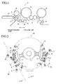
- FIG. 1 shows a beverage manufacturing line 2 which carries out molding of a plastic bottle 1 as an article to filling of beverage.
- the beverage manufacturing line 2 includes a blow molding line 3 which blow-molds parison to be the plastic bottle 1, and a filling line 4 which performs treatment such as washing and filling of beverage for the plastic bottle 1 which is blow-molded.
- the beverage manufacturing line 2 is controlled by control means not illustrated.
- the above described blow molding line 3 includes a preheater 3a which preheats the parison, and a blow molder 3b which blow-molds the parison to the plastic bottle 1.
- the filling line 4 includes a rinser 4a which washes the plastic bottle 1, a filler 4b which fills beverage in the plastic bottle 1, and a capper 4c which fits a cap to the plastic bottle 1.
- the above described beverage manufacturing line 2 includes a plurality of rotary wheels H which convey the parison and the plastic bottles 1.
- the adjacent rotary wheels H are rotated in the opposite directions from one another, and thereby, convey the parison and the plastic bottles 1 along a path shown by the thick line in FIG. 1 .
- the beverage manufacturing line 2 is divided into the above described blow molding line 3 and the filling line 4 at the position of the two-dot chain line in FIG. 1 , and each of the blow molding line 3 and the filling line 4 is synchronously driven by at least one servomotor.
- FIG. 2 shows rotary wheels H located in the boundary of the blow molding line 3 and the filling line 4.
- the rotary wheel H at a downstream end of the blow molding line 3 will be called an upstream side wheel Ha
- the rotary wheel H at an upstream side of the filling line 4 will be called a downstream side wheel Hb
- the rotary wheel H which is located further at a downstream side of the downstream side wheel Hb will be called a rotary wheel Hc.
- blow molding line 3 and the filling line 4 themselves are conventionally known, and therefore, the detailed description of the above described preheater 3a, blow molder 3b, rinser 4a, filler 4b and capper 4c will be omitted.
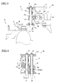
- the downstream side wheel Hb Describing the above described downstream side wheel Hb at first, the downstream side wheel Hb includes a base 11 fixed to the ground, a rotary table 12 which rotates around the base 11 in the counterclockwise direction shown in the drawing, and a plurality of grippers A having opening and closing mechanisms.
- An encoder not illustrated is disposed in a rotary part of the above described downstream side wheel Hb, as rotational position detecting means, so that the above described control means recognizes the rotational position of each of the grippers A provided at the downstream side wheel Hb by pulses outputted by the encoder.
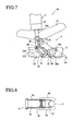
- the grippers A shown in FIGS. 5 and 6 among them are in a use state by the retreating means C, and the gripper A shown in FIG. 7 is in a retreated state by the retreating means C.
- the gripper A is moved in the right direction from the left shown in the drawings.
- the gripper A includes two first and second rotary shafts 21 and 22 axially supported rotatably by two plates 12a and 12b constituting the rotary table 12, a first grip member 23 fixed to the first rotary shaft 21, a second grip member 24 fixed to the second rotary shaft 22, a first gear member 25 fixed to the first rotary shaft 21, a second gear member 26 fixed to the second rotary shaft 22, and biasing means 27 which is provided at the above described first rotary shaft 21 and biases the first and second grip members 23 and 24 in the closing direction.
- first and second rotary shafts 21 and 22 are axially supported by the above described plates 12a and 12b via bearings respectively. Lower end portions of the first and second rotary shafts 21 and 22 are projected downward through the lower plate 12b, and to their tip ends, base end portions of the above described first and second grip members 23 and 24 are fixed respectively.
- first and second grip members 23 and 24 grip a neck portion 1a of the plastic bottle 1 from left and right sides, and a tip end of the first grip member 23 is made shorter than a tip end of the second grip member 24 so as to be in a preferable shape for delivering the plastic bottle 1.
- first and second gear members 25 and 26 are located between the above described plates 12a and 12b, the first gear member 25 is fixed to the first rotary shaft 21 to be rotated integrally with the first grip member 23, whereas the second gear member 26 is fixed to the second rotary shaft 22 to be rotated integrally with the second grip member 24.
- Gears are formed on the first and second gear members 25 and 26 to be meshed with each other, and when the first gear member 25 rotates around the first rotary shaft 21 to open or close the first grip member 23, the second gear member 26 operates with this and rotates around the second rotary shaft 22 to open or close the second grip member 24.
- the above described biasing means 27 is constituted of a sleeve 27a fixed to an upper end of the first rotary shaft 21, a transmitting member 27b axially supported rotatably by the first rotary shaft 21 at an upper portion of the above described first gear member 25, and a spring member 27c resiliently fitted between the sleeve 27a and the transmitting member 27b.
- FIGS. 5 to 7 illustrations of the sleeve 27a and the spring member 27c are omitted.
- a long hole 25a vertically penetrating through the first gear member 25 is formed, and a through-hole 27d is vertically formed in the above described transmitting member 27b.
- a connecting rod 28 is inserted into the long hole 25a and the through-hole 27d.
- the connecting rod 28 is movable along the long hole 25a, and therefore, the first gear member 25 and the transmitting member 27b are mutually rotatable around the first rotary shaft 21 within the range of the long hole 25a.
- the above described spring member 27c biases the above described first gear member 25 counterclockwise with respect to the transmitting member 27b, as a result of which, the first grip member 23 is kept in the closed state by the spring member 27c, and the second grip member 24 is linked to this and is also kept in the closed state as shown in FIG. 5 .
- the above described gripper A also includes a pin 26a provided at the above described second gear member 26, an engaging member 29 axially supported rotatably by the second rotary shaft 22, and a cam follower 30 provided at one end of the engaging member 29, and the cam follower 30 is engaged with a cam 31 fixed to the base 11.
- a substantially hook-shaped engaging part 29a which engages with the above described pin 26a is formed at a tip end of the above described engaging member 29.
- the above described cam follower 30 is provided at the other end of the engaging member 29, and when the cam follower 30 engages with the above described cam 31 and moves to the outer circumferential side of the rotary table 12, it rotates the engaging member 29 in the counterclockwise direction in the drawings.
- the engaging member 29 presses the pin 26a in the counterclockwise direction via the engaging part 29a, and as a result, the second gear member 26 rotates against the biasing force of the above described biasing means 27. Therefore, the second grip member 24 is opened as shown in FIG. 6 , and the first grip member 23 is linked to it and is also opened.
- the above described retreating means C is constituted of an air cylinder 32 as drive means, and a connecting member 33 in a substantially horseshoe shape, which is provided at a tip end of a rod 32a of the air cylinder 32, and holds the above described connecting rod 28.
- a base portion of the above described air cylinder 32 is rotatably held by the above described rotary table 12 and is connected to an air supply source not illustrated.
- the above described rod 32a is extended as shown in FIGS. 5 and 6 when the gripper A is brought into a use state and is contracted as shown in FIG. 7 when it is brought into a retreat state, by the control of the above described control means.
- the rod 32a of the air cylinder 32 keeps the extended state to hold the connecting rod 28 in a predetermined position in the use state, and allows the above described first and second grip members 23 and 24 to operate to open and close against the biasing force of the above described biasing means 27.
- the opening degrees in the retreat state are larger.
- the upstream side wheel Ha includes a base (not illustrated) fixed to the ground, a rotary table 41 which rotates in the counterclockwise direction in the drawing with respect to the base, and a plurality of grippers B which are provided at the rotary table 41 equidistantly in the circumferential direction and do not perform opening and closing operations for themselves.
- the gripper B is constituted of a stay 43 fixed to the rotary table 41, two plate springs 44 provided at both sides of the stay 43, a grip member 45 provided at a tip end of each of the plate springs 44, a spring 46 which biases the above described grip members 45 in the direction to move close to each other, and a support member 47 provided between both the grip members 45.
- the above described grip member 45 grips the plastic bottle 1 at the position lower than the neck portion 1a which the above described gripper A grips, and a tip end of it is in a hooked shape for preventing it from falling off.
- the grip members 45 in the gripper B are always biased in the closing direction by the above described plate springs 44 and the spring 46, and therefore, when gripping and releasing the plastic bottle 1, the above described grip members 45 need to be forcefully opened against the biasing forces of the above described plate springs 44 and spring 46.
- the rotary wheel Hc adjacent to the above described downstream side wheel Hb downstream from it also has substantially the same constitution as the upstream side wheel Ha, and includes grippers B similar to the grippers B of the above described upstream side wheel Ha.
- the plastic bottle 1 is supplied to the gripper B of the upstream side wheel Ha from the rotary wheel H adjacent to it at the upstream side, and the gripper B, which is in the state of gripping the plastic bottle 1, moves to the position adjacent to the above described downstream side wheel Hb by rotation of the rotary table 41.
- the gripper A of the above described downstream side wheel Hb is kept in the use state by the above described retreating means C.
- the above described cam follower 30 engages with the above described cam 31, and the first and second grip members 23 and 24 open.
- the first and second grip members 23 and 24 have the maximum opening degree in the use state shown in FIG. 6 at the position a little near to the upstream side from the position in which the upstream side wheel Ha and the downstream side wheel Hb are the closest to each other.
- the gripper B locates the plastic bottle 1 between the first and second grip members 23 and 24.
- the cam follower 30 is moved to the outer circumferential side by the cam 31, and the first and second grip members 23 and 24 are closed by the biasing force of the biasing means 27. Subsequently, in the position in which both the wheels Ha and Hb are the closest to each other, the first and second grip members 23 and 24 are in the closed state shown in FIG. 5 , and at this instant, the gripper B and the gripper A are in the state in which they grip the plastic bottle 1 simultaneously.
- the gripper B and the gripper A move away from each other, and since at this time, the plastic bottle 1 is gripped by the gripper A, the grip members 45 of the gripper B are pressed to be opened by the plastic bottle 1. Finally, the plastic bottle 1 is released from the gripper B, and delivery of the plastic bottle 1 is completed.
- the plastic bottle 1 needs to be simultaneously gripped with the gripper B and the gripper A, and therefore, the locus of the gripper B by the upstream side wheel Ha and the locus of the gripper A by the downstream side wheel Hb have to overlap one another.
- a delivery position for the plastic bottle 1 such a range in which the locus of the gripper B and the locus of the gripper A overlap one another and delivery of the plastic bottle 1 is performed will be called a delivery position for the plastic bottle 1.
- Such a delivery position exists between the downstream side wheel Hb and the rotary wheel Hc adjacent to it downstream from it, and delivery of the plastic bottle 1 from the gripper A of the downstream side wheel Hb to the gripper B of the rotary wheel Hc is performed.
- the first and second grip members 23 and 24 of the gripper A keep the closed state up to the position in which the downstream side wheel Hb and the rotary wheel Hc are the closest to each other, and just before this position, the plastic bottle 1 which the gripper A grips presses and opens the grip members of the gripper B of the rotary wheel Hc.
- the gripper A and the gripper B simultaneously grip the plastic bottle 1. Thereafter, the cam follower 30 and the cam 31 are engaged with each other and the first and second grip members 23 and 24 are opened. The plastic bottle 1 is released from the gripper A and delivery is completed.
- the operation of the filling line 4 is desired to be continued until the treatment of the plastic bottle 1 at least in the filling line 4 is finished from the viewpoint of hygiene.
- the operation of the blow molding line 3 is desired to be continued until at least the plastic bottle 1 in the blow molder 3b is discharged from the viewpoint of prevention of damage of the blow molder 3b.
- blow molding line 3 and the filling line 4 of this embodiment are driven by the different servo motors, and therefore, even if one device stops, the operation of the other device can be continued.
- the locus of the gripper B and the locus of the gripper A overlap one another in the above described delivery position as described above, and therefore, when the upstream side wheel Ha stops with abnormal stoppage of, for example, the blow molding line 3, if the downstream side wheel Hb of the filling line 4 is rotated continuously, there is the fear that the grippers A interfere with the plastic bottles 1 gripped by the grippers B, and the grippers are broken.
- the control means which detects this immediately controls the retreating means C of the gripper A of the downstream side wheel Hb which is located in the above described delivery position to switch the gripper A from the use state to the retreat state.
- control means always recognizes the position of each of the grippers A by a pulse from the encoder provided in the rotary part of the downstream side wheel Hb.
- control means controls the air cylinder 32 constituting the retreating means C of the gripper A which is located in the delivery position that is set in advance to cause the rod 32a to contract.
- the opening degree of the first and second grip members 23 and 24 in this opened state is larger than the opening degree in the above described use state, and therefore, the tip ends of the first and second grip members 23 and 24 are located at the inner circumferential side of the rotary table 12 from the position when they are in the use state.
- the first and second grip members 23 and 24 of the gripper A which are brought into the retreat state can pass without interfering with the plastic bottle 1 held by the gripper B stopping in the above described delivery position.
- some of the grippers A located in the delivery position have already received the plastic bottle 1 from the gripper B, and in this case, if such a gripper A is brought into the retreat state, the plastic bottle 1 is released and drops.
- a collection box as collecting means not illustrated is provided below the delivery position to collect the plastic bottles 1 which have dropped.
- the control means which detects it immediately controls the retreating means C of the gripper A located in the above described delivery position, and switches the gripper A to the retreat state from the use state.
- the plastic bottle 1 which is gripped by the gripper B can pass without interfering with the first and second grip members 23 and 24 of the gripper A which is stopping and in the retreat state.
- the plastic bottle 1 gripped by the gripper A located in the delivery position drops because the first and second grip members 23 and 24 are in the opened state, and is collected in the above described collection box.
- the plastic bottle 1 gripped by the above described gripper B is not delivered to the gripper A since the above described gripper A is in the retreat state, and is conveyed past the delivery position.
- a discharge bar not illustrated as collecting means is provided at a downstream side from the above described delivery position, and when the plastic bottle 1 abuts on the discharge bar, the grip members 45 of the above described gripper B are pressed and opened by the plastic bottle 1, and grip on the plastic bottle 1 is forcefully released.
- the plastic bottle 1 is released from the gripper B, and drops in a collection box provided near the discharge bar to be collected.
- a conveyor can be disposed to convey the plastic bottle 1 which has dropped thereon to a predetermined position.
- FIG. 9 a second embodiment according to the present invention will be described by using FIG. 9 .
- the members common to those in the above described first embodiment will be described by adding 100 to each of the reference numerals used in the first embodiment.
- the grippers A each having the opening and closing mechanism are provided at the downstream side wheel Hb, but a beverage manufacturing line 2 of the second embodiment adopts a constitution in which the grippers A each having the opening and closing mechanism are provided at the upstream side wheel Ha and the grippers B which do not perform opening and closing operations for themselves are provided at the downstream side wheel Hb.
- the upstream side wheel Ha in this embodiment includes the grippers A and the retreating means C having the same constitutions as those of the grippers A and the retreating means C in the above described first embodiment, and the downstream side wheel Hb includes the grippers B having the same constitutions as those of the grippers B in the above described first embodiment.
- the gripper A of the upstream side wheel Ha is kept in the use state by the retreating means C, and a plastic bottle 101 is delivered from the gripper A to the gripper B in the similar procedure to that followed when the plastic bottle 1 is delivered to the gripper B of the rotary wheel Hc from the gripper A of the downstream side wheel Hb in the above described first embodiment.
- the control means switches the gripper A located in the delivery position to the retreat state from the use state by the retreating means C. (See FIG. 7 )
- the plastic bottle 101 which is already gripped by the gripper B can pass without interfering with first and second grip members 123 and 124 of the gripper A which stop and are brought into the retreat position.
- the plastic bottle 101 which is gripped by the gripper A located in the delivery position drops since the first and second grip members 123 and 124 are brought into the opened state, and is collected into a collection box as collecting means which is installed below the delivery position.
- the control means switches the gripper A located in the delivery position by the retreating means C to the retreat state from the use state.
- the first and second grip members 123 and 124 are brought into the opened state, and the plastic bottle 101 gripped by the gripper A drops into the above described collection box. Therefore, the plastic bottle 101 which is gripped by the first and second grip members 123 and 124 of the gripper A does not interfere with the grip member of the gripper B which stops in the above described delivery position.
- the gripper A which newly reaches the delivery position by the rotation of a rotary table 112 is also switched to the retreat state by the retreating means C, and the plastic bottle 101 gripped by the gripper A also drops into the collection box to be collected.
- the gripper A which passes the delivery position is switched to the use state from the retreat state again by the retreating means C, and the gripper A receives the plastic bottle 101 from the rotary wheel H adjacent to the upstream side of the upstream side wheel Ha.
- FIGS. 10 and 11 Next, a third embodiment according to the present invention will be described by using FIGS. 10 and 11 .
- the constitutions of the gripper A and the retreating means C differ from those of the above described first embodiment.
- the difference will be described hereinafter, and the members corresponding to respective members of the above described first embodiment will be described by adding 200 to each of the reference numerals used in the first embodiment.
- the gripper A has an opening and closing mechanism, and includes a first grip member 223 fixed to a first rotary shaft 221, a second grip member 224 fixed to a second rotary shaft 222, a first gear member 225 fixed to the first rotary shaft 221, a second gear member 226 fixed to the second rotary shaft 222, and biasing means not illustrated which is provided at the above described first rotary shaft 221 to bias the first and second grip members 223 and 224 in a closing direction.
- the second grip member 224 is provided with an arm part 224a toward an inner circumferential side of a rotary table 212, and a cam follower 230 is provided at a tip end of the arm part 224a.
- Cams 231 are provided respectively at a delivery position of the plastic bottles by the upstream side wheel Ha and the downstream side wheel Hb, and a delivery position of the plastic bottles by the downstream side wheel Hb and the rotary wheel Hc.
- the retreating means C of this embodiment is a moving mechanism 232 which moves the cam 231 provided at the delivery position for the above described upstream side wheel Ha and the downstream side wheel Hb, and for the moving mechanism 232, for example, an air cylinder can be used.
- the moving mechanism 232 locates the cam 231 in the use position as shown in FIG. 10 , and when a blow molding line or a filling line abnormally stops, it locates the cam 231 in the retreat position as shown in FIG. 11 .
- the opening degree of the first and second grip members 223 and 224 when the cam 231 is located in the use position is the opening degree optimal for receiving a plastic bottle from the gripper B of the upstream side wheel Ha in the delivery position.
- the opening degree of the first and second grip members 223 and 224 when the cam 231 is located in the retreat position is larger as compared with the opening degree when the cam 231 is located in the above described use position.
- tip ends of the first and second grip members 223 and 224 can be prevented from interfering with the plastic bottle gripped by the gripper B of the upstream side wheel Ha.
- the constitution in which the upstream side wheel Ha is provided with the grippers A having the opening and closing mechanisms and the retreating means C, and the downstream side wheel Hb is provided with the grippers B which do not perform opening and closing operations for themselves may be adopted.
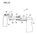
- FIG. 12 a fourth embodiment according to the present invention will be described.
- the members corresponding to the respective members of the above described first embodiment will be described by adding 300 to each of the reference numerals used in the first embodiment.
- the upstream side wheel Ha of this embodiment is provided with the grippers A each having an opening and closing mechanism, and the downstream side wheel Hb is provided with the grippers B which have the same constitutions as the grippers B in the above described first embodiment and do not perform opening and closing operations for themselves.
- the retreating means C is provided at the gripper B which does not perform an opening and closing operation for itself.
- the retreating means C includes an air cylinder 351 provided at a rotary table 312, a cylindrical bearing member 353 fixed to the rotary table 312 via a stay 352, and a moving member 354 which advances and retreats in the above described bearing member 353 with the above described air cylinder 351 connected to a base end portion and the above described gripper B connected to a tip end portion.
- Each of the air cylinders 351 extends and contracts the rod 351a in the radial direction of the rotary table 312, and advances and retreats the above described moving member 354 in the radial direction to be able to move the gripper B to the use position at an outer circumferential side of the rotary table 312 and the retreat position at an inner circumferential side.
- a plurality of bearings are provided inside the above described bearing member 353, the moving member 354 and the bearing member 353 are covered with a bellows-shaped protection member 355.
- the above described retreating means C extends the rod 351a of the air cylinder 351 to locate the gripper B in the use position and brings it into a use state.
- a plastic bottle 301 is delivered in the delivery position for the upstream side wheel Ha and the downstream side wheel Hb in the similar procedure as that for the delivery of the plastic bottle 1 between the downstream side wheel Hb and the rotary wheel Hc in the above described first embodiment.
- the control means which detects it immediately controls the retreating means C of the gripper B located in the delivery position to switch the gripper B to a retreat state from the use state.
- control means recognizes the position of each of the grippers B by a pulse from an encoder provided in a rotary part of the downstream side wheel Hb, and moves the gripper B located in the range of the delivery position which is set in advance to the retreat position from the above described use position.
- some of the grippers B which move to the above described retreat position receive the plastic bottles 301 from the grippers A, and therefore, the control means moves the grippers B which are retreated when the upstream side wheel Ha abnormally stops to the use position again after the grippers B pass the receiving position to cause them to deliver the plastic bottles 301 to the downstream side rotary wheel Hc.
- control means also controls the air cylinder 351 to move the grippers B to the retreat position from the normal position.
- the gripper B By bringing the gripper B into the retreat state like this, the plastic bottle 301 gripped by the gripper A and the gripper B are prevented from interfering with each other, or the gripper A is prevented from interfering with the plastic bottle 301 which the gripper B holds.
- the plastic bottle 301 is not received by the gripper B in the delivery position, and therefore, the plastic bottle 301 drops from the gripper A in the delivery position so that the plastic bottle 301 drops into a collection box provided near the delivery position.
- the fifth embodiment has a constitution in which the upstream side wheel Ha is provided with the grippers B which do not perform opening and closing operations for themselves and the retreating means C, as the relation of the first embodiment and the second embodiment.
- the gripper B of the upstream side wheel Ha is located in a use position by the retreating means C, and the plastic bottle is delivered from the gripper B to the gripper A which is provided at the downstream side wheel Hb and has the opening and closing mechanism.
- control means moves the gripper B located in the delivery position to a retreat position by the retreating means C.
- the control means moves the gripper B located in the delivery position to the retreat position by the retreating means C.
- the plastic bottle held by the gripper B passes the delivery position without being delivered to the gripper A, and therefore, the control means returns the gripper B which has passed the delivery position from the retreat state to the use state again.
Applications Claiming Priority (1)
| Application Number | Priority Date | Filing Date | Title |
|---|---|---|---|
| JP2007067303A JP5211517B2 (ja) | 2007-03-15 | 2007-03-15 | 物品搬送装置 |
Publications (2)
| Publication Number | Publication Date |
|---|---|
| EP1970329A1 true EP1970329A1 (de) | 2008-09-17 |
| EP1970329B1 EP1970329B1 (de) | 2010-04-21 |
Family
ID=39462009
Family Applications (1)
| Application Number | Title | Priority Date | Filing Date |
|---|---|---|---|
| EP08250638A Active EP1970329B1 (de) | 2007-03-15 | 2008-02-25 | Artikelfördervorrichtung |
Country Status (6)
| Country | Link |
|---|---|
| US (1) | US7681713B2 (de) |
| EP (1) | EP1970329B1 (de) |
| JP (1) | JP5211517B2 (de) |
| KR (1) | KR101465641B1 (de) |
| CN (1) | CN101264857B (de) |
| DE (1) | DE602008001013D1 (de) |
Cited By (7)
| Publication number | Priority date | Publication date | Assignee | Title |
|---|---|---|---|---|
| EP2388196A1 (de) * | 2010-05-17 | 2011-11-23 | Krones AG | Rotierende Vorrichtung und Verfahren zum Überführen von Artikeln |
| EP2239215A3 (de) * | 2009-04-08 | 2012-07-18 | Shibuya Kogyo Co., Ltd | Artikeltragevorrichtung |
| EP2511206A1 (de) | 2011-04-13 | 2012-10-17 | Krones AG | Transportvorrichtung zum Tranportieren von Behältern |
| EP2226274A3 (de) * | 2009-03-04 | 2013-06-05 | Krones AG | Vorrichtung zum Behandeln von Behältnissen mit direkt angetriebenem Transportrad |
| EP3254993A1 (de) * | 2016-06-10 | 2017-12-13 | Sidel Participations | Artikelfördervorrichtung, verfahren zum betrieb solch einer artikelfördervorrichtung und artikelhandhabungsvorrichtung mit mindestens einer solchen artikelfördervorrichtung |
| WO2018046874A3 (fr) * | 2016-11-09 | 2018-05-03 | Sidel Participations | Systeme de convoyage d'objets en matiere thermoplastique comportant un corps creux muni d'un col |
| EP3912937A1 (de) * | 2020-05-20 | 2021-11-24 | Krones Ag | Vorrichtung zum vorgeben einer klammerarmposition und behältertransportvorrichtung |
Families Citing this family (30)
| Publication number | Priority date | Publication date | Assignee | Title |
|---|---|---|---|---|
| JP5160789B2 (ja) * | 2004-02-02 | 2013-03-13 | クロネス・アクチェンゲゼルシャフト | 物品の動的蓄積装置 |
| DE202004016069U1 (de) | 2004-10-16 | 2005-12-01 | Krones Ag | Vorrichtung zum Puffern von Gegenständen |
| DE202005013552U1 (de) | 2005-08-27 | 2005-11-03 | Krones Ag | Dynamischer Speicher für Gegenstände |
| FR2890062B1 (fr) * | 2005-08-29 | 2008-10-31 | Sidel Sas | Dispositif de chargement ou de dechargement de recipients comportant un col sur un element de transport |
| FR2890061A1 (en) * | 2005-08-29 | 2007-03-02 | Sidel Sas | Container loader for transporter has ejector for incorrectly loaded containers equipped with receiver synchronised with movement of gripper |
| DE102006008123A1 (de) * | 2006-02-20 | 2007-08-23 | Krones Ag | Vorrichtung zum Speichern von Gegenständen |
| DE102006012148A1 (de) | 2006-03-16 | 2007-09-20 | Krones Ag | Fördermittel |
| DE102006035109A1 (de) * | 2006-07-29 | 2008-01-31 | Krones Ag | Fördereinrichtung |
| FR2919595B1 (fr) * | 2007-08-01 | 2009-11-20 | Sidel Participations | Dispositif de convoyage de recipients divisant un flux principal de recipients en une pluralite de flux secondaires |
| JP5256766B2 (ja) * | 2008-02-18 | 2013-08-07 | 澁谷工業株式会社 | 物品処理装置 |
| JP5332603B2 (ja) * | 2008-12-26 | 2013-11-06 | 大日本印刷株式会社 | 飲料充填方法及び装置 |
| CN103625699B (zh) | 2008-05-20 | 2016-05-11 | 大日本印刷株式会社 | 饮料填充方法和装置 |
| JP5402038B2 (ja) * | 2009-02-06 | 2014-01-29 | 大日本印刷株式会社 | 飲料充填装置 |
| JP5332672B2 (ja) * | 2009-02-06 | 2013-11-06 | 大日本印刷株式会社 | 飲料充填方法及び装置 |
| JP2010189023A (ja) * | 2009-02-17 | 2010-09-02 | Dainippon Printing Co Ltd | 飲料充填装置 |
| DE102008062064A1 (de) * | 2008-12-12 | 2010-06-17 | Krones Ag | Verfahren zur Steuerung einer Maschine zur Behandlung von Behältern |
| DE102009005181A1 (de) * | 2009-01-15 | 2010-07-29 | Khs Ag | Behälterbehandlungsmaschine |
| DE102009021277A1 (de) | 2009-05-11 | 2010-11-18 | Khs Corpoplast Gmbh & Co. Kg | Verfahren und Vorrichtung zur Blasformung sowie zum Befüllen von Behältern |
| FR2948315B1 (fr) * | 2009-07-21 | 2015-04-24 | Sidel Participations | Dispositif pour le convoyage de recipients dans une unite de chauffage |
| DE102009040363A1 (de) | 2009-09-07 | 2011-03-10 | Krones Ag | Vorrichtung und Verfahren zum Herstellen von Kunststoffflaschen |
| DE102010036028A1 (de) * | 2010-08-31 | 2012-03-01 | Khs Gmbh | Verfahren zum Herstellen und Behandeln von Behältern |
| JP5799420B2 (ja) * | 2010-11-10 | 2015-10-28 | キリンテクノシステム株式会社 | ペットボトルのリーク検査装置 |
| JP5725097B2 (ja) * | 2013-07-31 | 2015-05-27 | 大日本印刷株式会社 | 飲料充填装置 |
| JP2014015265A (ja) * | 2013-08-30 | 2014-01-30 | Dainippon Printing Co Ltd | 飲料充填装置 |
| DE102015106103B4 (de) * | 2015-04-21 | 2018-01-18 | Khs Gmbh | Behältergreifer sowie Transportvorrichtung zum Transportieren von Behältern |
| CA2984441C (en) * | 2015-04-30 | 2023-05-23 | Fillshape S.R.L. | System and method for transferring pouches |
| DE102016101985B4 (de) * | 2016-02-04 | 2018-06-21 | Khs Gmbh | Transportstern zum Führen von Behältern in einer Behälterbehandlungsanlage |
| GB201704394D0 (en) * | 2017-03-20 | 2017-05-03 | Axis Tech And Dev Ltd | Mushroom handling apparatus |
| JP6803785B2 (ja) * | 2017-03-29 | 2020-12-23 | 三菱重工機械システム株式会社 | 搬送システム |
| US10800611B2 (en) * | 2018-04-27 | 2020-10-13 | Shibuya Corporation | Container conveyor system |
Citations (3)
| Publication number | Priority date | Publication date | Assignee | Title |
|---|---|---|---|---|
| JPH11502175A (ja) | 1995-03-23 | 1999-02-23 | シデル | 直列形瓶詰め設備 |
| EP1245513A1 (de) * | 2001-03-30 | 2002-10-02 | Shibuya Kogyo Co., Ltd | Fördersystem für Plastikbehälter |
| JP2003502238A (ja) | 1999-06-21 | 2003-01-21 | クロネス・アクチェンゲゼルシャフト | 瓶容器の充填装置 |
Family Cites Families (14)
| Publication number | Priority date | Publication date | Assignee | Title |
|---|---|---|---|---|
| US2275978A (en) * | 1938-05-05 | 1942-03-10 | Ball Brothers Co | Setting over mechanism |
| US3718216A (en) * | 1969-04-01 | 1973-02-27 | Bliss Co | Forming press system and workpiece handling and transfer apparatus therefor |
| US3590982A (en) * | 1969-05-19 | 1971-07-06 | Owens Illinois Inc | Article transfer apparatus |
| US5232717A (en) * | 1988-07-13 | 1993-08-03 | Nissei Asb Machine Co., Ltd. | Preform carrying apparatus |
| FR2731176B1 (fr) * | 1995-03-02 | 1997-04-30 | Sidel Sa | Installation de fabrication de recipients par soufflage de preformes en matiere plastique |
| ES2129902T3 (es) * | 1995-05-13 | 1999-06-16 | Hermann Kronseder | Rueda transportadora en estrella para recipientes. |
| CN2308451Y (zh) * | 1997-09-19 | 1999-02-24 | 财团法人工业技术研究院 | 空瓶自动整列装置 |
| FR2802191B1 (fr) * | 1999-12-13 | 2002-03-01 | Sidel Sa | Dispositif de convoyage d'entites discretes comportant un bras de transfert perfectionne et installation de soufflage de recipients munie d'un tel dispositif |
| JP4491905B2 (ja) * | 1999-12-15 | 2010-06-30 | 澁谷工業株式会社 | 容器搬送システム |
| JP4639507B2 (ja) * | 2001-03-30 | 2011-02-23 | 澁谷工業株式会社 | 樹脂ボトルの搬送装置 |
| JP3902070B2 (ja) * | 2002-05-29 | 2007-04-04 | 株式会社フジシールインターナショナル | スパウト付き袋状容器の製造方法及びスパウト付き袋状容器の製造装置並びにスパウト供給装置 |
| CN2581378Y (zh) * | 2002-09-25 | 2003-10-22 | 长沙楚天包装机械有限公司 | 过渡输瓶机构 |
| FR2867171B1 (fr) * | 2004-03-05 | 2007-06-08 | Sidel Sa | Dispositif de convoyage comportant un bras de transfert ameliore |
| JP4461990B2 (ja) * | 2004-09-30 | 2010-05-12 | 澁谷工業株式会社 | 角形物品の受け渡し装置 |
-
2007
- 2007-03-15 JP JP2007067303A patent/JP5211517B2/ja active Active
-
2008
- 2008-02-19 US US12/070,506 patent/US7681713B2/en active Active
- 2008-02-25 EP EP08250638A patent/EP1970329B1/de active Active
- 2008-02-25 DE DE602008001013T patent/DE602008001013D1/de active Active
- 2008-03-06 KR KR1020080020800A patent/KR101465641B1/ko active IP Right Grant
- 2008-03-14 CN CN2008100853738A patent/CN101264857B/zh active Active
Patent Citations (3)
| Publication number | Priority date | Publication date | Assignee | Title |
|---|---|---|---|---|
| JPH11502175A (ja) | 1995-03-23 | 1999-02-23 | シデル | 直列形瓶詰め設備 |
| JP2003502238A (ja) | 1999-06-21 | 2003-01-21 | クロネス・アクチェンゲゼルシャフト | 瓶容器の充填装置 |
| EP1245513A1 (de) * | 2001-03-30 | 2002-10-02 | Shibuya Kogyo Co., Ltd | Fördersystem für Plastikbehälter |
Cited By (10)
| Publication number | Priority date | Publication date | Assignee | Title |
|---|---|---|---|---|
| EP2226274A3 (de) * | 2009-03-04 | 2013-06-05 | Krones AG | Vorrichtung zum Behandeln von Behältnissen mit direkt angetriebenem Transportrad |
| EP2239215A3 (de) * | 2009-04-08 | 2012-07-18 | Shibuya Kogyo Co., Ltd | Artikeltragevorrichtung |
| EP2388196A1 (de) * | 2010-05-17 | 2011-11-23 | Krones AG | Rotierende Vorrichtung und Verfahren zum Überführen von Artikeln |
| US8678172B2 (en) | 2010-05-17 | 2014-03-25 | Krones Ag | Rotary device for the transport of articles |
| EP2511206A1 (de) | 2011-04-13 | 2012-10-17 | Krones AG | Transportvorrichtung zum Tranportieren von Behältern |
| DE102011007308A1 (de) | 2011-04-13 | 2012-10-18 | Krones Aktiengesellschaft | Transportvorrichtung zum Transportieren von Behältern |
| EP3254993A1 (de) * | 2016-06-10 | 2017-12-13 | Sidel Participations | Artikelfördervorrichtung, verfahren zum betrieb solch einer artikelfördervorrichtung und artikelhandhabungsvorrichtung mit mindestens einer solchen artikelfördervorrichtung |
| WO2018046874A3 (fr) * | 2016-11-09 | 2018-05-03 | Sidel Participations | Systeme de convoyage d'objets en matiere thermoplastique comportant un corps creux muni d'un col |
| CN109963798A (zh) * | 2016-11-09 | 2019-07-02 | 西得乐集团 | 输送包括配有颈部的中空体的热塑性材料物件的系统 |
| EP3912937A1 (de) * | 2020-05-20 | 2021-11-24 | Krones Ag | Vorrichtung zum vorgeben einer klammerarmposition und behältertransportvorrichtung |
Also Published As
| Publication number | Publication date |
|---|---|
| JP5211517B2 (ja) | 2013-06-12 |
| US7681713B2 (en) | 2010-03-23 |
| US20080223691A1 (en) | 2008-09-18 |
| JP2008222428A (ja) | 2008-09-25 |
| CN101264857B (zh) | 2012-10-17 |
| EP1970329B1 (de) | 2010-04-21 |
| DE602008001013D1 (de) | 2010-06-02 |
| KR101465641B1 (ko) | 2014-11-27 |
| KR20080084617A (ko) | 2008-09-19 |
| CN101264857A (zh) | 2008-09-17 |
Similar Documents
| Publication | Publication Date | Title |
|---|---|---|
| EP1970329B1 (de) | Artikelfördervorrichtung | |
| EP3907162A1 (de) | Anlage zur verarbeitung von behältern | |
| EP2001774B1 (de) | Transportsystem für flaschen oder dergleichen behälter sowie anlage zum behandeln von flaschen oder dergleichen behälter | |
| CN109757102B (zh) | 用于容器的传输系统 | |
| KR101517560B1 (ko) | 물품 처리 장치 | |
| KR101695449B1 (ko) | 물품 반송 장치 | |
| EP2321207B1 (de) | Übertragungsgerät | |
| DE102011007280A1 (de) | Behälterbehandlungsmaschine und Verfahren zur Behälterbehandlung | |
| US9254967B2 (en) | Module for aligning containers and method for aligning containers | |
| US10106388B2 (en) | Container processing machine and method for delivering containers to and/or removing them from a container processing machine | |
| EP0608823A1 (de) | Vorrichtung zum Einwickeln, insbesondere für Lebensmittel wie Süsswaren oder dergleichen | |
| US20040025909A1 (en) | Device for inverting a hollow body | |
| CN113165810A (zh) | 用于输送和转移容器的间隔星轮 | |
| JP2011529409A (ja) | プラスチック容器、特にボトルをブロー成形するためのプラントの成形ユニット | |
| JPH11314752A (ja) | ボトル搬送装置 | |
| CN109963798B (zh) | 输送包括配有颈部的中空体的热塑性材料物件的系统 | |
| JP2011529410A (ja) | プラスチック容器、特にボトルをブロー成形するためのプラント | |
| EP3747828A1 (de) | Vorrichtung zum anbringen von kap verschlusskappen | |
| JP6657909B2 (ja) | 物品搬送装置 | |
| CN113165814B (zh) | 用于热塑性材料的容器的传送星形轮 | |
| JP6207954B2 (ja) | 容器搬送システム | |
| CN113044280B (zh) | 装套装置及贴标机 | |
| JP2022178084A (ja) | 充填システム |
Legal Events
| Date | Code | Title | Description |
|---|---|---|---|
| PUAI | Public reference made under article 153(3) epc to a published international application that has entered the european phase |
Free format text: ORIGINAL CODE: 0009012 |
|
| AK | Designated contracting states |
Kind code of ref document: A1 Designated state(s): AT BE BG CH CY CZ DE DK EE ES FI FR GB GR HR HU IE IS IT LI LT LU LV MC MT NL NO PL PT RO SE SI SK TR |
|
| AX | Request for extension of the european patent |
Extension state: AL BA MK RS |
|
| 17P | Request for examination filed |
Effective date: 20081112 |
|
| AKX | Designation fees paid |
Designated state(s): DE FR IT |
|
| GRAP | Despatch of communication of intention to grant a patent |
Free format text: ORIGINAL CODE: EPIDOSNIGR1 |
|
| GRAS | Grant fee paid |
Free format text: ORIGINAL CODE: EPIDOSNIGR3 |
|
| GRAA | (expected) grant |
Free format text: ORIGINAL CODE: 0009210 |
|
| AK | Designated contracting states |
Kind code of ref document: B1 Designated state(s): DE FR IT |
|
| REF | Corresponds to: |
Ref document number: 602008001013 Country of ref document: DE Date of ref document: 20100602 Kind code of ref document: P |
|
| PLBE | No opposition filed within time limit |
Free format text: ORIGINAL CODE: 0009261 |
|
| STAA | Information on the status of an ep patent application or granted ep patent |
Free format text: STATUS: NO OPPOSITION FILED WITHIN TIME LIMIT |
|
| 26N | No opposition filed |
Effective date: 20110124 |
|
| REG | Reference to a national code |
Ref country code: DE Ref legal event code: R081 Ref document number: 602008001013 Country of ref document: DE Owner name: DAI NIPPON PRINTING CO., LTD., JP Free format text: FORMER OWNER: SHIBUYA KOGYO CO., LTD., KANAZAWA, ISHIKAWA, JP Effective date: 20131107 Ref country code: DE Ref legal event code: R081 Ref document number: 602008001013 Country of ref document: DE Owner name: SHIBUYA KOGYO CO., LTD., KANAZAWA, JP Free format text: FORMER OWNER: SHIBUYA KOGYO CO., LTD., KANAZAWA, ISHIKAWA, JP Effective date: 20131107 Ref country code: DE Ref legal event code: R082 Ref document number: 602008001013 Country of ref document: DE Representative=s name: LEINWEBER & ZIMMERMANN, DE Effective date: 20131107 Ref country code: DE Ref legal event code: R081 Ref document number: 602008001013 Country of ref document: DE Owner name: SHIBUYA KOGYO CO., LTD., JP Free format text: FORMER OWNER: SHIBUYA KOGYO CO., LTD., KANAZAWA, JP Effective date: 20131107 Ref country code: DE Ref legal event code: R081 Ref document number: 602008001013 Country of ref document: DE Owner name: DAI NIPPON PRINTING CO., LTD., JP Free format text: FORMER OWNER: SHIBUYA KOGYO CO., LTD., KANAZAWA, JP Effective date: 20131107 |
|
| REG | Reference to a national code |
Ref country code: FR Ref legal event code: TQ Owner name: DAI NIPPON PRINTING CO., LTD., JP Effective date: 20131204 Ref country code: FR Ref legal event code: TQ Owner name: SHIBUYA KOGYO CO., LTD., JP Effective date: 20131204 |
|
| REG | Reference to a national code |
Ref country code: FR Ref legal event code: PLFP Year of fee payment: 9 |
|
| REG | Reference to a national code |
Ref country code: FR Ref legal event code: PLFP Year of fee payment: 10 |
|
| REG | Reference to a national code |
Ref country code: FR Ref legal event code: PLFP Year of fee payment: 11 |
|
| PGFP | Annual fee paid to national office [announced via postgrant information from national office to epo] |
Ref country code: FR Payment date: 20230110 Year of fee payment: 16 |
|
| PGFP | Annual fee paid to national office [announced via postgrant information from national office to epo] |
Ref country code: IT Payment date: 20230110 Year of fee payment: 16 Ref country code: DE Payment date: 20221230 Year of fee payment: 16 |