EP1967485A1 - Flurförderzeug - Google Patents
Flurförderzeug Download PDFInfo
- Publication number
- EP1967485A1 EP1967485A1 EP08002609A EP08002609A EP1967485A1 EP 1967485 A1 EP1967485 A1 EP 1967485A1 EP 08002609 A EP08002609 A EP 08002609A EP 08002609 A EP08002609 A EP 08002609A EP 1967485 A1 EP1967485 A1 EP 1967485A1
- Authority
- EP
- European Patent Office
- Prior art keywords
- hydraulic
- proportional valve
- adjusting cylinder
- fork
- valve
- Prior art date
- Legal status (The legal status is an assumption and is not a legal conclusion. Google has not performed a legal analysis and makes no representation as to the accuracy of the status listed.)
- Granted
Links
Images

Classifications
-
- B—PERFORMING OPERATIONS; TRANSPORTING
- B66—HOISTING; LIFTING; HAULING
- B66F—HOISTING, LIFTING, HAULING OR PUSHING, NOT OTHERWISE PROVIDED FOR, e.g. DEVICES WHICH APPLY A LIFTING OR PUSHING FORCE DIRECTLY TO THE SURFACE OF A LOAD
- B66F9/00—Devices for lifting or lowering bulky or heavy goods for loading or unloading purposes
- B66F9/06—Devices for lifting or lowering bulky or heavy goods for loading or unloading purposes movable, with their loads, on wheels or the like, e.g. fork-lift trucks
- B66F9/075—Constructional features or details
- B66F9/20—Means for actuating or controlling masts, platforms, or forks
- B66F9/22—Hydraulic devices or systems
-
- B—PERFORMING OPERATIONS; TRANSPORTING
- B66—HOISTING; LIFTING; HAULING
- B66F—HOISTING, LIFTING, HAULING OR PUSHING, NOT OTHERWISE PROVIDED FOR, e.g. DEVICES WHICH APPLY A LIFTING OR PUSHING FORCE DIRECTLY TO THE SURFACE OF A LOAD
- B66F9/00—Devices for lifting or lowering bulky or heavy goods for loading or unloading purposes
- B66F9/06—Devices for lifting or lowering bulky or heavy goods for loading or unloading purposes movable, with their loads, on wheels or the like, e.g. fork-lift trucks
- B66F9/075—Constructional features or details
- B66F9/12—Platforms; Forks; Other load supporting or gripping members
- B66F9/14—Platforms; Forks; Other load supporting or gripping members laterally movable, e.g. swingable, for slewing or transverse movements
- B66F9/142—Movements of forks either individually or relative to each other
- B66F9/144—Movements of forks relative to each other - independent
-
- B—PERFORMING OPERATIONS; TRANSPORTING
- B66—HOISTING; LIFTING; HAULING
- B66F—HOISTING, LIFTING, HAULING OR PUSHING, NOT OTHERWISE PROVIDED FOR, e.g. DEVICES WHICH APPLY A LIFTING OR PUSHING FORCE DIRECTLY TO THE SURFACE OF A LOAD
- B66F9/00—Devices for lifting or lowering bulky or heavy goods for loading or unloading purposes
- B66F9/06—Devices for lifting or lowering bulky or heavy goods for loading or unloading purposes movable, with their loads, on wheels or the like, e.g. fork-lift trucks
- B66F9/075—Constructional features or details
- B66F9/12—Platforms; Forks; Other load supporting or gripping members
- B66F9/16—Platforms; Forks; Other load supporting or gripping members inclinable relative to mast
Definitions
- the invention relates to an industrial truck according to claim 1.
- the invention relates to an industrial truck, which also has auxiliary functions in addition to a lifting and lowering function for a load-receiving means, in particular for the load-carrying means.
- Such a truck is about out DE 698 07 098 T4 07/15/2004 known.
- the lifting and lowering function is the process of the fork from the mast away or on this to accomplish by means of an adjusting cylinder and also the pivoting of the lifting device.
- a so-called three-way stacker has become known, in which the fork can also be pivoted about a vertical axis.
- the tilting and sideshift functions of a load handler as well as optional attachments mounted on a height-adjustable support are usually operated via proportional valves. Between the proportional valve, which is usually located in the drive part and the consumer on the mast are often several meters hydraulic hose. For a feature request the hydraulic hose is pressurized. He expands while doing so. Since the secondary functions only require a small volume flow, for example 6 to 8 liters per minute, the effect described results in a clear response delay of the secondary functions. This effect occurs more frequently with longer hoses, ie with larger lifting heights, and larger payloads, since with the length of the hose and increasing pressure also the storage capacity of the hoses increases.
- the invention has for its object to provide a truck with the mast to be operated auxiliary functions in which the response delay of the secondary functions is reduced.
- the proportional valve is mounted on the carrier, and on the drive part, a switching valve is arranged, which connects the hydraulic hose selectively with the hydraulic pump or separates from this.
- the hoses can be filled with a significantly higher volume flow than is necessary for the supply of the functions, since the throttle point no longer starts, but instead output (load side) of the hydraulic hoses.
- the speed of the pump can provide the required pressure reserve.
- the output pressure of the hydraulic pump is directly at the proportional valve. This ensures that the volume flow demand of the consumer at all times sufficient reserves, which leads to a significantly more constant operating speed, in particular if further consumers are to be supplied by the pump.
- the pump speed can be significantly increased for a short time after a secondary function has been requested.
- the invention is particularly suitable for a function of the lateral displacement of the fork and a tilt adjustment of the fork about a horizontal axis.
- an adjusting cylinder is required for each function.
- These can be controlled according to an embodiment of the invention via a common proportional valve having a neutral position and two working positions, each working position is associated with a hydraulic cylinder.
- the invention provides that a pressure compensator associated with the proportional valve is mounted on the carrier.
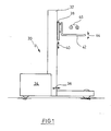
- An in Fig. 1 illustrated reach truck 30 has a mast 32 which is held on the drive member 34 and by means of a hydraulic cylinder, not shown, along the double arrow 36 is displaceable.
- a support 38 is adjustable in height, as indicated by double arrow 40.
- a load fork 42 is mounted, which is pivotable about a horizontal axis with the aid of an adjusting cylinder, also not shown, as indicated by double arrow 44.
- the load fork 42 is also displaceable along a horizontal axis relative to the carrier 38, as indicated by arrow ends 46. Again, an adjusting cylinder is required.
- Fig. 2 is a lifting cylinder 23 for the mast 32 to recognize, which is connected via a load-holding and lowering valve 21 and a pressure compensator 22 to a hydraulic pump 1.
- an adjusting cylinder 5 is provided, for example, for the inclination of the fork 42.
- An adjusting cylinder 6 is for the side thrust of the fork 42 in accordance with 46 in Fig. 1 intended.
- An adjusting cylinder 17 is provided for the mast thrust 36.
- the hydraulic adjusting cylinders 5, 6 and 17 are also supplied by the hydraulic pump 1, which is driven by an electric motor, not shown. It sucks hydraulic medium from a tank 20.
- a pressure line 9 from the pump 1 leads to a switching valve 10, which shuts off the pressure line 9 in the illustrated neutral position.
- a pressure relief valve 19 responds in order to return medium to the tank 20.
- From the switching valve 10 go from two pressure lines 7, 8, in the form of Hydraulic hoses to the hydraulic cylinders 5, 6 are guided. They may have a length of several meters, depending on the maximum lifting height of the fork 42.
- a pressure compensator 2 and a proportional valve 11 is arranged at the end of the hydraulic lines 7, 8, a pressure compensator 2 and a proportional valve 11 is arranged.
- the proportional valve 11 has a neutral position, in which both hydraulic cylinders 5, 6 are not supplied with medium. In one working position, a supply of one of the two hydraulic cylinders 5, 6 takes place in accordance with the controlled electromagnet for the proportional valve. In this case, the pressure compensator 2 ensures that a controlled volume flow is supplied to the hydraulic cylinder 5 and 6, respectively. It depends on the switching position of the switching valve 10, which side of the hydraulic valve 5 and 6 supplied with pressure medium and which side is connected to the tank 10.
- the hydraulic unit (valve block) of pressure compensator 2 and proportional valve 11, which is scrapped by a dot-dash line 26, is located on the carrier 38 for the load fork 42.
- a proportional valve 16 preceded by a pressure compensator 24, is also in the vehicle, i. housed in the drive part 34 and provides for the proportional control of the working cylinder 17 for the mast thrust.
- valve block 25 according to Fig. 2 is located on the vehicle.
- Q is the volume flow at the pump speed n.
- Q 1.1 is the volume flow at the pump speed n 1 .
- the pump 1 provides the required pressure reserve p 1.1 .
- the pressure p 1.1 between the pump 1 and 2 pressure compensator is greater p 2.1 , ie at the entrance of the cylinder 5 and 6. This ensures that the volume flow requirement of the hydraulic cylinder 5, the sixth always have enough reserves, which leads to a constant speed of operation.
- the pump speed can be significantly increased for a short time after a function has been requested.
- Volume flow Q 2.1 between the proportional valve 11 and cylinder 5 or 6 and pressure p 2.1 are thereby uniform, and the pressure in the lines 7, 8 is compensated.
Landscapes
- Engineering & Computer Science (AREA)
- Transportation (AREA)
- Structural Engineering (AREA)
- Civil Engineering (AREA)
- Life Sciences & Earth Sciences (AREA)
- Geology (AREA)
- Mechanical Engineering (AREA)
- Chemical & Material Sciences (AREA)
- Combustion & Propulsion (AREA)
- Forklifts And Lifting Vehicles (AREA)
Abstract
Description
- Die Erfindung bezieht sich auf ein Flurförderzeug nach Anspruch 1. Insbesondere bezieht sich die Erfindung auf ein Flurförderzeug, das neben einer Heben- und Senkenfunktion für ein Lastaufnahmemittel auch Nebenfunktionen aufweist, insbesondere für das Lastaufnahmemittel.
- Ein derartiges Flurförderzeug ist etwa aus
DE 698 07 098 T4 2004.07.15 bekannt geworden. Neben der Heben- und Senkenfunktion ist das Verfahren der Lastgabel vom Hubmast fort bzw. auf diesen zu mit Hilfe eines Verstellzylinders zu bewerkstelligen sowie ferner das Schwenken des Lastaufnahmemittels. Es ist auch bekannt, das Lastaufnahmemittel, z.B. die Lastgabel, nicht nur um eine horizontale Achse zu kippen, sondern auch entlang einer horizontalen Achse seitlich zu verschieben. Schließlich ist auch ein sogenannter Dreiseitenstapler bekannt geworden, bei dem die Lastgabel zudem um eine vertikale Achse verschwenkt werden kann. - Die Betätigung der einzelnen Funktionen in den Flurförderzeugen erfolgt üblicherweise auf hydraulischem Wege. Im Antriebsteil des Flurförderzeugs ist eine motorbetriebene Hydraulikpumpe angeordnet, die über Schläuche mit den Steuerventilen für die einzelnen Funktionen verbunden ist.
- Die Funktionen Neigen und Seitenschub eines Lastaufnahmemittels sowie auch optionaler Anbaugeräte, die an einem höhenverstellbaren Träger angebaut sind, werden üblicherweise über Proportionalventile betätigt. Zwischen dem Proportionalventil, das zumeist im Antriebsteil angeordnet ist und dem Verbraucher am Hubgerüst liegen oft mehrere Meter Hydraulikschlauch. Bei einer Funktionsanforderung wird der Hydraulikschlauch mit Druck beaufschlagt. Er dehnt sich dabei aus. Da die Nebenfunktionen nur einen geringen Volumenstrom benötigen, zum Beispiel 6 bis 8 Liter pro Minute, resultiert aus dem beschriebenen Effekt eine deutliche Ansprechverzögerung der Nebenfunktionen. Dieser Effekt tritt verstärkt bei längeren Schläuchen, d.h. bei größeren Hubhöhen, und größeren Nutzlasten auf, da mit der Länge des Schlauchs und steigendem Druck auch das Speichervermögen der Schläuche steigt.
- Der Erfindung liegt die Aufgabe zugrunde, ein Flurförderzeug mit am Hubgerüst zu betätigenden Nebenfunktionen zu schaffen, bei dem die Ansprechverzögerung der Nebenfunktionen reduziert ist.
- Diese Aufgabe wird durch die Merkmale des Patentanspruchs 1 gelöst.
- Bei der Erfindung ist das Proportionalventil am Träger angebracht, und am Antriebsteil ist ein Schaltventil angeordnet, das den Hydraulikschlauch wahlweise mit der Hydraulikpumpe verbindet oder von dieser trennt.
- Wird das Proportionalventil unmittelbar am Träger, zum Beispiel für die Lastgabel, in der Nähe der Last positioniert, so können die Schläuche mit deutlich höherem Volumenstrom befüllt werden als dies für die Versorgung der Funktionen notwendig ist, da sich die Drosselstelle nun nicht mehr eingangs, sondern ausgangs (lastseitig) der Hydraulikschläuche befindet. Hierdurch verringert sich die Ansprechzeit der Funktionen, da die durch die Schlauchdehnung verursachte Totzeit aufgrund der höher einzustellenden Pumpendrehzahl reduziert wird. Nach der Befüllungsphase des Hydraulikschlauchs kann die Drehzahl der Pumpe für die benötigte Druckreserve sorgen. Der Ausgangsdruck der Hydraulikpumpe steht unmittelbar am Proportionalventil an. Dadurch wird gewährleistet, daß der Volumenstromanforderung des Verbrauchers jederzeit genügend Reserven gegenüberstehen, was zu einer deutlich konstanteren Funktionsgeschwindigkeit führt, insbesondere wenn weitere Verbraucher von der Pumpe zu versorgen sind.
- Um die Totzeit bis zum vollständigen Befüllen der Schläuche noch weiter zu verringern, kann nach Anforderung einer Nebenfunktion die Pumpendrehzahl kurzzeitig deutlich überhöht werden.
- Die Erfindung ist insbesondere geeignet für eine die Funktion des seitlichen Verschiebens der Lastgabel und einer Neigungsverstellung der Lastgabel um eine horizontale Achse. Für jede Funktion ist ein Verstellzylinder erforderlich. Diese können nach einer Ausgestaltung der Erfindung über ein gemeinsames Proportionalventil angesteuert werden, das eine Neutralstellung aufweist sowie zwei Arbeitsstellungen, wobei jeder Arbeitsstellung ein Hydraulikzylinder zugeordnet ist.
- Es ist üblich, bei einer Ansteuerung über ein Proportionalventil eine Druckwaage vorzusehen, um den eingestellten Volumenstrom zu regeln. Daher sieht die Erfindung vor, daß auch eine dem Proportionalventil zugeordnete Druckwaage am Träger angebracht ist.
- Zusammenfassend kann daher festgestellt werden, daß durch die erfindungsgemäße Anordnung der Ventile ausgangsseitig bzw. lastseitig der Schläuche der Staudruck vor dem Proportionalventil nicht eingangsseitig, sondern ausgangsseitig, d.h. also lastseitig der Hydraulikschläuche erzeugt wird und damit höher ausfallen kann. Volumenstrom und Druck werden dadurch gleichmäßig, und der Druckverlust in den Leitungen wird kompensiert.
- Die Erfindung wird nachfolgend anhand von Zeichnungen näher erläutert.
- Fig. 1
- zeigt äußerst schematisch die Seitenansicht eines Schubmaststaplers.
- Fig. 2
- zeigt eine hydraulische Schaltungsanordnung für den Schubmaststapler nach
Fig. 1 . - Ein in
Fig. 1 dargestellter Schubmaststapler 30 weist ein Hubgerüst 32 auf, das am Antriebsteil 34 gehalten und mit Hilfe eines nicht gezeigten Hydraulikzylinders entlang des Doppelpfeils 36 verschiebbar ist. Am Hubgerüst 32 ist ein Träger 38 in der Höhe verstellbar, wie durch Doppelpfeil 40 angedeutet. Am Träger 38 ist eine Lastgabel 42 angebracht, die mit Hilfe eines ebenfalls nicht gezeigten Verstellzylinders um eine horizontale Achse verschwenkbar ist, wie durch Doppelpfeil 44 angedeutet. Die Lastgabel 42 ist außerdem entlang einer horizontalen Achse gegenüber dem Träger 38 verschiebbar, wie durch Pfeilenden 46 angedeutet. Auch hierfür ist ein Verstellzylinder erforderlich. - In
Fig. 2 ist ein Hubzylinder 23 für das Hubgerüst 32 zu erkennen, der über ein Lasthalte- und Senkenventil 21 und eine Druckwaage 22 an eine Hydraulikpumpe 1 anschließbar ist. - In
Fig. 2 ist ferner ein Verstellzylinder 5 beispielsweise für die Neigung der Lastgabel 42 vorgesehen. Ein Verstellzylinder 6 ist für den Seitenschub der Lastgabel 42 gemäß 46 inFig. 1 vorgesehen. Ein Verstellzylinder 17 ist für den Mastschub 36 vorgesehen. - Die hydraulischen Verstellzylinder 5, 6 und 17 werden ebenfalls von der Hydraulikpumpe 1 versorgt, die von einem nicht gezeigten Elektromotor angetrieben ist. Sie saugt Hydraulikmedium aus einem Tank 20. Eine Druckleitung 9 von der Pumpe 1 führt zu einem Schaltventil 10, das in der dargestellten Neutralstellung die Druckleitung 9 absperrt. Bei Überdruck spricht ein Überdruckventil 19 an, um Medium in den Tank 20 zurückzuleiten. Vom Schaltventil 10 gehen zwei Druckleitungen 7, 8 ab, die in Form von Hydraulikschläuchen zu den Hydraulikzylindern 5, 6 geführt sind. Sie können eine Länge von mehreren Metern aufweisen, je nach maximaler Hubhöhe der Lastgabel 42. Am Ende der Hydraulikleitungen 7, 8 ist eine Druckwaage 2 sowie ein Proportionalventil 11 angeordnet. Diese beiden hydraulischen Komponenten befinden sich am Träger 38 gemäß
Fig. 1 . Das Proportionalventil 11 weist eine Neutralstellung auf, in der beide Hydraulikzylinder 5, 6 nicht mit Medium versorgt werden. In der einen Arbeitsstellung erfolgt eine Versorgung eines der beiden Hydraulikzylinder 5, 6 nach Maßgabe des angesteuerten Elektromagneten für das Proportionalventil. Dabei sorgt die Druckwaage 2 dafür, daß ein geregelter Volumenstrom dem Hydraulikzylinder 5 bzw. 6 zugeführt wird. Es hängt von der Schaltstellung des Schaltventils 10 ab, welche Seite des Hydraulikventils 5 bzw. 6 mit Druckmittel versorgt und welche Seite mit dem Tank 10 verbunden wird. - Die von einer strichpunktierten Linie 26 eingekästelte Hydraulikeinheit (Ventilblock) aus Druckwaage 2 und Proportionalventil 11 befindet sich am Träger 38 für die Lastgabel 42.
- Ein Proportionalventil 16, dem eine Druckwaage 24 vorgeschaltet ist, ist ebenfalls im Fahrzeug, d.h. im Antriebsteil 34 untergebracht und sorgt für die proportionale Ansteuerung des Arbeitszylinders 17 für den Mastschub.
- Der Ventilblock 25 gemäß
Fig. 2 befindet sich am Fahrzeug. - Während der Befüllungsphase der Hydraulikleitungen (Schläuche) 7, 8 ist Q1.1 > Q1. Q ist der Volumenstrom bei der Pumpendrehzahl n. Q1.1 ist der Volumenstrom bei der Pumpendrehzahl n1. Während der Bewegungsphase ist Q1.1 größer oder gleich Q1. Nach der Befüllungsphase des Schlauchs sorgt die Drehzahl n, der Pumpe 1 für die benötigte Druckreserve p1.1. Der Druck p1.1 zwischen Pumpe 1 und Druckwaage 2 ist größer p2.1, d.h. am Eingang der Zylinder 5 bzw. 6. Dadurch ist gewährleistet, daß der Volumenstromanforderung der Hydraulikzylinder 5, 6 jederzeit genügend Reserven gegenüberstehen, was zu einer konstanten Funktionsgeschwindigkeit führt.
- Um die Totzeit bis zum vollständigen Befüllen der Hydraulikschläuche 7, 8 weiter zu verringern, kann nach Anforderung einer Funktion die Pumpendrehzahl kurzzeitig deutlich überhöht werden. Volumenstrom Q2.1 zwischen Proportionalventil 11 und Zylinder 5 oder 6 und Druck p2.1 werden dadurch gleichmäßiger, und der Druck in den Leitungen 7, 8 wird kompensiert.
- Generell gelten folgende Bezeichnungen:


Claims (5)
- Flurförderzeug mit einem Antriebsteil und einem Lastteil, wobei das Lastteil ein Hubgerüst aufweist, an dem ein Träger für eine Lastgabel oder ein Anbaugerät höhenverstellbar geführt ist und dem Träger mindestens ein hydraulischer Verstellzylinder zugeordnet ist für eine Verstellung der Lastgabel oder eines Teils am Anbaugerät und wobei im Antriebsteil eine von einem Motor angetriebene Hydraulikpumpe angeordnet ist, die über ein Proportionalventil und Hydraulikschläuche mit dem Verstellzylinder verbunden ist, dadurch gekennzeichnet, daß das Proportionalventil (11) am Träger (38) angebracht ist und am Antriebsteil (34) ein Schaltventil (10) angeordnet ist, das die Hydraulikschläuche (7, 8) wahlweise mit der Hydraulikpumpe (1) verbindet oder von dieser trennt.
- Flurförderzeug nach Anspruch 1, dadurch gekennzeichnet, daß die Lastgabel (42) seitlich verschiebbar und/oder in ihrer Neigung zur Horizontalen verschwenkt gelagert ist und ein Verstellzylinder für die Verschiebung und/oder die Neigung vorgesehen ist.
- Flurförderzeug nach Anspruch 2, dadurch gekennzeichnet, daß die beiden Verstellzylinder (5, 6) über ein Proportionalventil (11) mit den Hydraulikschläuchen (7, 8) verbunden sind, das eine Neutralstellung und zwei Arbeitsstellungen aufweist, wobei jeweils eine Arbeitsstellung einem Verstellzylinder (5, 6) zugeordnet ist.
- Flurförderzeug nach einem der Ansprüche 1 bis 3, dadurch gekennzeichnet, daß eine dem Proportionalventil (11) vorgeschaltete Druckwaage (2) ebenfalls am Träger (38) angeordnet ist.
- Flurförderzeug nach einem der Ansprüche 1 bis 4, dadurch gekennzeichnet, daß eine Steuervorrichtung vorgesehen ist, die bei einer Betätigung eines Verstellzylinders (5, 6) den Pumpenmotor (1) so ansteuert, daß er kurzzeitig eine überhöhte Drehzahl aufweist.
Applications Claiming Priority (1)
| Application Number | Priority Date | Filing Date | Title |
|---|---|---|---|
| DE102007010697A DE102007010697A1 (de) | 2007-03-06 | 2007-03-06 | Flurförderzeug |
Publications (2)
| Publication Number | Publication Date |
|---|---|
| EP1967485A1 true EP1967485A1 (de) | 2008-09-10 |
| EP1967485B1 EP1967485B1 (de) | 2013-12-25 |
Family
ID=39577884
Family Applications (1)
| Application Number | Title | Priority Date | Filing Date |
|---|---|---|---|
| EP08002609.9A Active EP1967485B1 (de) | 2007-03-06 | 2008-02-13 | Flurförderzeug |
Country Status (3)
| Country | Link |
|---|---|
| US (1) | US20080217110A1 (de) |
| EP (1) | EP1967485B1 (de) |
| DE (1) | DE102007010697A1 (de) |
Cited By (1)
| Publication number | Priority date | Publication date | Assignee | Title |
|---|---|---|---|---|
| WO2012094211A1 (en) * | 2011-01-04 | 2012-07-12 | Crown Equipment Corporation | Materials handling vehicle having a manifold located on a power unit for maintaining fluid pressure at an output port at a commanded pressure corresponding to an auxiliary device operating pressure |
Families Citing this family (3)
| Publication number | Priority date | Publication date | Assignee | Title |
|---|---|---|---|---|
| US8026625B2 (en) * | 2007-06-20 | 2011-09-27 | California Institute Of Technology | Power generation systems and methods |
| KR101529330B1 (ko) * | 2009-12-23 | 2015-06-29 | 주식회사 두산 | 지게차의 포크 작동 유압장치 |
| WO2014011459A1 (en) * | 2012-07-11 | 2014-01-16 | Mercury Capital Management L.L.C. | Lift automated guided vehicle for warehouse tray handling |
Citations (5)
| Publication number | Priority date | Publication date | Assignee | Title |
|---|---|---|---|---|
| US5292219A (en) * | 1990-02-23 | 1994-03-08 | Auramo Cargo Systems Oy | Procedure and apparatus for the handling of loads |
| EP1067296A1 (de) * | 1999-07-06 | 2001-01-10 | HEILMEIER & WEINLEIN Fabrik für Oel-Hydraulik GmbH & Co. KG | Elektrohydraulischer Hubmodul |
| DE69807098T2 (de) | 1997-09-30 | 2003-04-10 | Crown Equipment Corp., New Bremen | Produktivitätspaket |
| JP2003267682A (ja) * | 2002-03-14 | 2003-09-25 | Nippon Yusoki Co Ltd | フォークリフト |
| EP1760033A2 (de) | 2005-09-06 | 2007-03-07 | Auramo OY | Kontrollsystem für ein Lasthandhabungsgerät |
Family Cites Families (19)
| Publication number | Priority date | Publication date | Assignee | Title |
|---|---|---|---|---|
| US4157467A (en) * | 1978-03-17 | 1979-06-05 | Crown Controls Corporation | Sequential control system for a lift truck |
| US4335992A (en) * | 1980-01-07 | 1982-06-22 | Towmotor Corporation | Side shift fork adjustable carriage |
| US4284384A (en) * | 1980-03-03 | 1981-08-18 | Cascade Corporation | Apparatus for automatically depositing a load in a predetermined position |
| US4523886A (en) * | 1982-01-13 | 1985-06-18 | Towmotor Corporation | Container handler with programmed electro-hydraulic control circuit |
| US4755100A (en) * | 1985-11-12 | 1988-07-05 | Clark Equipment Company | Operator control system |
| JPS63230497A (ja) * | 1987-03-20 | 1988-09-26 | 日産自動車株式会社 | 産業車両の荷役装置 |
| US4902190A (en) * | 1987-09-14 | 1990-02-20 | Cascade Corporation | Fork positioning attachment for lift trucks |
| FR2628589B1 (fr) | 1988-03-14 | 1994-03-04 | Etat Francais | Codeur differentiel a filtre predicteur auto-adaptatif et decodeur utilisable en liaison avec un tel codeur |
| US5139385A (en) * | 1990-04-03 | 1992-08-18 | Swingshift Manufacturing, Inc. | Dual pallet fork attachment for a lift truck |
| US5190436A (en) * | 1991-06-06 | 1993-03-02 | Caterpillar Industrial Inc. | Carriage assembly having side shiftable and adjustable forks |
| JP2862111B2 (ja) * | 1992-03-17 | 1999-02-24 | 三菱重工業株式会社 | フォークリフトの制御装置 |
| US5586620A (en) * | 1995-05-12 | 1996-12-24 | Crown Equipment Corporation | Remote viewing apparatus for fork lift trucks |
| US5669750A (en) * | 1996-07-19 | 1997-09-23 | Vieselmeyer; Lee R. | Loader attachment |
| JP2000109299A (ja) * | 1998-10-02 | 2000-04-18 | Nippon Yusoki Co Ltd | カウンタバランス型フォ−クリフトの荷役装置 |
| DE19903157C2 (de) * | 1999-01-27 | 2002-11-21 | Kaup Gmbh & Co Kg | Anbaugerät für Flurförderzeuge mit einem Hubmast, insbesondere für Gabelstapler |
| JP2001316096A (ja) * | 2000-02-28 | 2001-11-13 | Toyota Industries Corp | 産業車両の油圧装置 |
| JP4201122B2 (ja) * | 2003-01-24 | 2008-12-24 | 日本輸送機株式会社 | リーチ式フォークリフト |
| DE102004011913B4 (de) * | 2004-03-11 | 2005-12-29 | Jungheinrich Ag | Hydraulische Hubvorrichtung für batteriebetriebene Flurförderzeuge |
| US8091467B2 (en) * | 2008-04-30 | 2012-01-10 | Cascade Corporation | Hydraulic valve circuit with damage-control override |
-
2007
- 2007-03-06 DE DE102007010697A patent/DE102007010697A1/de not_active Ceased
-
2008
- 2008-02-13 EP EP08002609.9A patent/EP1967485B1/de active Active
- 2008-03-03 US US12/041,134 patent/US20080217110A1/en not_active Abandoned
Patent Citations (5)
| Publication number | Priority date | Publication date | Assignee | Title |
|---|---|---|---|---|
| US5292219A (en) * | 1990-02-23 | 1994-03-08 | Auramo Cargo Systems Oy | Procedure and apparatus for the handling of loads |
| DE69807098T2 (de) | 1997-09-30 | 2003-04-10 | Crown Equipment Corp., New Bremen | Produktivitätspaket |
| EP1067296A1 (de) * | 1999-07-06 | 2001-01-10 | HEILMEIER & WEINLEIN Fabrik für Oel-Hydraulik GmbH & Co. KG | Elektrohydraulischer Hubmodul |
| JP2003267682A (ja) * | 2002-03-14 | 2003-09-25 | Nippon Yusoki Co Ltd | フォークリフト |
| EP1760033A2 (de) | 2005-09-06 | 2007-03-07 | Auramo OY | Kontrollsystem für ein Lasthandhabungsgerät |
Cited By (2)
| Publication number | Priority date | Publication date | Assignee | Title |
|---|---|---|---|---|
| WO2012094211A1 (en) * | 2011-01-04 | 2012-07-12 | Crown Equipment Corporation | Materials handling vehicle having a manifold located on a power unit for maintaining fluid pressure at an output port at a commanded pressure corresponding to an auxiliary device operating pressure |
| US9290366B2 (en) | 2011-01-04 | 2016-03-22 | Crown Equipment Corporation | Materials handling vehicle having a manifold located on a power unit for maintaining fluid pressure at an output port at a commanded pressure corresponding to an auxiliary device operating pressure |
Also Published As
| Publication number | Publication date |
|---|---|
| EP1967485B1 (de) | 2013-12-25 |
| DE102007010697A1 (de) | 2008-09-11 |
| US20080217110A1 (en) | 2008-09-11 |
Similar Documents
| Publication | Publication Date | Title |
|---|---|---|
| EP3459904B2 (de) | Flurförderzeug, hydraulisches system für ein flurförderzeug und verfahren zum betreiben eines hydraulischen systems | |
| DE102007001510B4 (de) | Hydraulisches System mit mehrfachen Druckentlastungspegeln | |
| EP2113482B1 (de) | Hebevorrichtung | |
| EP1900676B1 (de) | Hebebühne zum Anheben von Lasten | |
| DE3042656A1 (de) | Hydraulisch betriebene hebebuehne | |
| DE102012101949A1 (de) | Hubvorrichtung eines Flurförderzeugs | |
| DE102017126386A1 (de) | Baumaschine mit Ausleger | |
| DE2208777A1 (de) | Scherenhebetisch | |
| DE112017003054T5 (de) | Hydraulisches ansteuersystem | |
| EP1967485B1 (de) | Flurförderzeug | |
| EP1943179B1 (de) | Hydraulikanlage | |
| DE102016103256A1 (de) | Flurförderzeug mit einem Hubgerüst | |
| DE102005059240A1 (de) | Hydrostatisches Antriebssystem | |
| EP3336050B1 (de) | Flurförderzeug mit einer steuereinheit zur regelung der bewegung einer kolbenstange eines hydraulikzylinders sowie ein solches verfahren | |
| DE3515762A1 (de) | Mehrsaeulen-hebebuehe od. dgl. und verfahren zur gleichlaufsteuerung ihrer hubelemente | |
| DE102017109421A1 (de) | Hydrauliksystem einer land- oder bauwirtschaftlich nutzbaren Arbeitsmaschine | |
| EP4385938B1 (de) | Ventileinrichtung für ein flurförderzeug | |
| EP1780171B1 (de) | Hubmast für Stapler | |
| DE3237019A1 (de) | Kraftfahrzeug mit zwei pumpen unterschiedlichen verdraengungsvolumens | |
| EP2551232B1 (de) | Kransteuerungssystem | |
| DE19816755B4 (de) | Scherenhubwagen mit einem elektrohydraulischen Antrieb | |
| DE19819270B4 (de) | Seitenstapler | |
| DE2658695A1 (de) | Betaetigungseinrichtung zur betaetigung von steuerorganen | |
| EP4725893A1 (de) | Verfahren zum betreiben eines mehrere hydraulikpumpen aufweisenden hydrauliksystems eines flurförderzeugs und flurförderzeug | |
| EP4190740B1 (de) | Hubmast für ein flurförderzeug mit zwei lasttragmitteln |
Legal Events
| Date | Code | Title | Description |
|---|---|---|---|
| PUAI | Public reference made under article 153(3) epc to a published international application that has entered the european phase |
Free format text: ORIGINAL CODE: 0009012 |
|
| AK | Designated contracting states |
Kind code of ref document: A1 Designated state(s): AT BE BG CH CY CZ DE DK EE ES FI FR GB GR HR HU IE IS IT LI LT LU LV MC MT NL NO PL PT RO SE SI SK TR |
|
| AX | Request for extension of the european patent |
Extension state: AL BA MK RS |
|
| 17P | Request for examination filed |
Effective date: 20090203 |
|
| 17Q | First examination report despatched |
Effective date: 20090324 |
|
| AKX | Designation fees paid |
Designated state(s): DE FR GB |
|
| 17Q | First examination report despatched |
Effective date: 20101130 |
|
| REG | Reference to a national code |
Ref country code: DE Ref legal event code: R079 Ref document number: 502008011111 Country of ref document: DE Free format text: PREVIOUS MAIN CLASS: B66F0009075000 Ipc: B66F0009140000 |
|
| GRAP | Despatch of communication of intention to grant a patent |
Free format text: ORIGINAL CODE: EPIDOSNIGR1 |
|
| INTG | Intention to grant announced |
Effective date: 20130809 |
|
| RIC1 | Information provided on ipc code assigned before grant |
Ipc: B66F 9/22 20060101ALI20130730BHEP Ipc: B66F 9/14 20060101AFI20130730BHEP Ipc: B66F 9/16 20060101ALI20130730BHEP |
|
| GRAS | Grant fee paid |
Free format text: ORIGINAL CODE: EPIDOSNIGR3 |
|
| GRAA | (expected) grant |
Free format text: ORIGINAL CODE: 0009210 |
|
| AK | Designated contracting states |
Kind code of ref document: B1 Designated state(s): DE FR GB |
|
| REG | Reference to a national code |
Ref country code: GB Ref legal event code: FG4D Free format text: NOT ENGLISH |
|
| REG | Reference to a national code |
Ref country code: DE Ref legal event code: R096 Ref document number: 502008011111 Country of ref document: DE Effective date: 20140213 |
|
| REG | Reference to a national code |
Ref country code: DE Ref legal event code: R097 Ref document number: 502008011111 Country of ref document: DE |
|
| PLBE | No opposition filed within time limit |
Free format text: ORIGINAL CODE: 0009261 |
|
| STAA | Information on the status of an ep patent application or granted ep patent |
Free format text: STATUS: NO OPPOSITION FILED WITHIN TIME LIMIT |
|
| 26N | No opposition filed |
Effective date: 20140926 |
|
| REG | Reference to a national code |
Ref country code: DE Ref legal event code: R097 Ref document number: 502008011111 Country of ref document: DE Effective date: 20140926 |
|
| REG | Reference to a national code |
Ref country code: FR Ref legal event code: PLFP Year of fee payment: 9 |
|
| REG | Reference to a national code |
Ref country code: FR Ref legal event code: PLFP Year of fee payment: 10 |
|
| REG | Reference to a national code |
Ref country code: FR Ref legal event code: PLFP Year of fee payment: 11 |
|
| PGFP | Annual fee paid to national office [announced via postgrant information from national office to epo] |
Ref country code: GB Payment date: 20210223 Year of fee payment: 14 |
|
| GBPC | Gb: european patent ceased through non-payment of renewal fee |
Effective date: 20220213 |
|
| PG25 | Lapsed in a contracting state [announced via postgrant information from national office to epo] |
Ref country code: GB Free format text: LAPSE BECAUSE OF NON-PAYMENT OF DUE FEES Effective date: 20220213 |
|
| PGFP | Annual fee paid to national office [announced via postgrant information from national office to epo] |
Ref country code: FR Payment date: 20230217 Year of fee payment: 16 |
|
| PG25 | Lapsed in a contracting state [announced via postgrant information from national office to epo] |
Ref country code: FR Free format text: LAPSE BECAUSE OF NON-PAYMENT OF DUE FEES Effective date: 20240229 |
|
| PG25 | Lapsed in a contracting state [announced via postgrant information from national office to epo] |
Ref country code: FR Free format text: LAPSE BECAUSE OF NON-PAYMENT OF DUE FEES Effective date: 20240229 |
|
| PGFP | Annual fee paid to national office [announced via postgrant information from national office to epo] |
Ref country code: DE Payment date: 20260217 Year of fee payment: 19 |