EP1967306A2 - Wendeschneidplatte und Bohrer damit - Google Patents
Wendeschneidplatte und Bohrer damit Download PDFInfo
- Publication number
- EP1967306A2 EP1967306A2 EP08003819A EP08003819A EP1967306A2 EP 1967306 A2 EP1967306 A2 EP 1967306A2 EP 08003819 A EP08003819 A EP 08003819A EP 08003819 A EP08003819 A EP 08003819A EP 1967306 A2 EP1967306 A2 EP 1967306A2
- Authority
- EP
- European Patent Office
- Prior art keywords
- insert
- drill
- recess
- cutting edge
- cutting
- Prior art date
- Legal status (The legal status is an assumption and is not a legal conclusion. Google has not performed a legal analysis and makes no representation as to the accuracy of the status listed.)
- Withdrawn
Links
- 230000002093 peripheral effect Effects 0.000 claims description 13
- 238000009434 installation Methods 0.000 claims description 7
- 230000000694 effects Effects 0.000 description 4
- 239000000463 material Substances 0.000 description 4
- 230000001154 acute effect Effects 0.000 description 3
- 102220005308 rs33960931 Human genes 0.000 description 3
- 238000011156 evaluation Methods 0.000 description 2
- 230000000149 penetrating effect Effects 0.000 description 2
- 230000000052 comparative effect Effects 0.000 description 1
- 230000002542 deteriorative effect Effects 0.000 description 1
- 238000010586 diagram Methods 0.000 description 1
- 238000005553 drilling Methods 0.000 description 1
- 230000014509 gene expression Effects 0.000 description 1
- 238000003754 machining Methods 0.000 description 1
- 238000004519 manufacturing process Methods 0.000 description 1
- 238000005259 measurement Methods 0.000 description 1
- 239000002184 metal Substances 0.000 description 1
Images



Classifications
-
- B—PERFORMING OPERATIONS; TRANSPORTING
- B23—MACHINE TOOLS; METAL-WORKING NOT OTHERWISE PROVIDED FOR
- B23B—TURNING; BORING
- B23B27/00—Tools for turning or boring machines; Tools of a similar kind in general; Accessories therefor
- B23B27/14—Cutting tools of which the bits or tips or cutting inserts are of special material
- B23B27/141—Specially shaped plate-like cutting inserts, i.e. length greater or equal to width, width greater than or equal to thickness
-
- B—PERFORMING OPERATIONS; TRANSPORTING
- B23—MACHINE TOOLS; METAL-WORKING NOT OTHERWISE PROVIDED FOR
- B23B—TURNING; BORING
- B23B51/00—Tools for drilling machines
-
- B—PERFORMING OPERATIONS; TRANSPORTING
- B23—MACHINE TOOLS; METAL-WORKING NOT OTHERWISE PROVIDED FOR
- B23B—TURNING; BORING
- B23B2200/00—Details of cutting inserts
- B23B2200/08—Rake or top surfaces
- B23B2200/086—Rake or top surfaces with one or more grooves
-
- B—PERFORMING OPERATIONS; TRANSPORTING
- B23—MACHINE TOOLS; METAL-WORKING NOT OTHERWISE PROVIDED FOR
- B23B—TURNING; BORING
- B23B2251/00—Details of tools for drilling machines
- B23B2251/50—Drilling tools comprising cutting inserts
-
- Y—GENERAL TAGGING OF NEW TECHNOLOGICAL DEVELOPMENTS; GENERAL TAGGING OF CROSS-SECTIONAL TECHNOLOGIES SPANNING OVER SEVERAL SECTIONS OF THE IPC; TECHNICAL SUBJECTS COVERED BY FORMER USPC CROSS-REFERENCE ART COLLECTIONS [XRACs] AND DIGESTS
- Y10—TECHNICAL SUBJECTS COVERED BY FORMER USPC
- Y10T—TECHNICAL SUBJECTS COVERED BY FORMER US CLASSIFICATION
- Y10T407/00—Cutters, for shaping
- Y10T407/23—Cutters, for shaping including tool having plural alternatively usable cutting edges
- Y10T407/235—Cutters, for shaping including tool having plural alternatively usable cutting edges with integral chip breaker, guide or deflector
-
- Y—GENERAL TAGGING OF NEW TECHNOLOGICAL DEVELOPMENTS; GENERAL TAGGING OF CROSS-SECTIONAL TECHNOLOGIES SPANNING OVER SEVERAL SECTIONS OF THE IPC; TECHNICAL SUBJECTS COVERED BY FORMER USPC CROSS-REFERENCE ART COLLECTIONS [XRACs] AND DIGESTS
- Y10—TECHNICAL SUBJECTS COVERED BY FORMER USPC
- Y10T—TECHNICAL SUBJECTS COVERED BY FORMER US CLASSIFICATION
- Y10T408/00—Cutting by use of rotating axially moving tool
- Y10T408/89—Tool or Tool with support
- Y10T408/905—Having stepped cutting edges
Definitions
- the present invention relates to an indexable insert and a drill (indexable drill) in which a plurality of indexable inserts are combined to define cutting edges.
- Drills used for drilling holes in a metal workpiece include a drill with its cutting edges defined by a plurality of indexable inserts (hereinafter, also merely referred to as inserts). Such a drill is disclosed in the following references and the like.
- Japanese Registered Utility Model No. 2582812 discloses an indexable insert for a drill, and a drill with its cutting edges defined by the inserts. In the configuration, a chip breaker is improved to smoothly dispose chips. Also, Japanese Unexamined Patent Application Publication No. 2002-307221 discloses an indexable insert for a drill with all around type breakers having breaker grooves in a rake face entirely along cutting edges. The Publication also discloses an indexable insert additionally having protrusions (protruding portions) in the breaker grooves.
- indexable insert (with the all around type breakers) having breaker walls along the cutting edges, instead of the breaker grooves, and an indexable insert having small breaker protrusions separately provided at the rake face.
- the indexable inserts with the all around type breakers may contain grooves that locally increase chip flow-out resistance to increase chip disposability (parting performance).
- each chip breaker efficiently applies warp to the flow-out chips, thereby efficiently disposing the chips.
- the contact area of the chips to the surface of the chip breaker is increased, the chip flow-out resistance and the cutting resistance may be increased.
- the chip flow-out resistance and the cutting resistance may be reduced.
- the chips come into contact with the small protrusions by point contact.
- the advantageous effect of the chip breaker may be reduced, and the chip disposability may deteriorate.
- An object of the present invention is to provide an indexable insert for a drill for reducing chip flow-out resistance, so as to provide efficient chip disposability and to reduce cutting resistance.
- the invention made improvements in a polygonal-shaped, indexable insert for a drill, having chip breakers provided at an upper face along cutting edges. At least one recess is provided at each chip breaker, the recess extending from a portion of the chip breaker near the cutting edge toward a center hole of the insert. The recess is retracted from an end of the chip breaker near the cutting edge toward the center of the insert by 0.2 mm or greater, or the recess communicates with (penetrates to) the center hole of the insert.
- the chip breaker may be have a breaker groove or may not have a breaker groove.
- the recess may be located in an area distant from an insert edge by 25% to 60% of an insert width, a distance from an end of the recess near the center hole to the center hole may be 0.5 mm or greater, a depth of the recess may be 0.1 mm or greater, or a position of the end of the chip breaker near the cutting edge may be higher than a position of the cutting edge.
- the expressions, the insert edge and the insert width, will be described later.
- the end of the recess near the center hole is retracted from the end of the chip breaker near the cutting edge by 0.2 mm or greater, however, if the distance from the end near the center hole to the center hole is smaller than 0.5 mm, the end near the center hole may penetrate to the center hole.
- a plurality of the indexable inserts thus configured are combined to define cutting edges, to constitute a drill.
- the drill has at a tip thereof a plurality of installation points, and the indexable inserts are detachably attached to the installation points with different installation distances to the drill center.
- the indexable inserts share a cutting area extending from the drill center to the periphery of the drill to perform cutting.
- the invention also provides the drill.
- the indexable insert of the invention has the recess at a longitudinally intermediate portion of the chip breaker provided along the cutting edge.
- a clearance is provided between chips and the insert at a portion with the recess. The clearance can reduce the contact area of the chips to the cutting edge. Accordingly, the chip flow-out resistance and the cutting resistance can be reduced.
- the chip breaker is continuously arranged along the cutting edge. Accordingly, the contact area of the chips to a breaker wall face is not excessively reduced unlike when the small breaker protrusions are employed. Thus, the chip disposability does not deteriorate.
- the retracted distance of the end of the recess near the center hole, from the end of the chip breaker near the cutting edge to the center of the insert is 0.2 mm or greater, or the recess penetrates to the center hole.
- the chips can be prevented from coming into contact with the bottom of the recess and the end thereof near the center hole.
- the recess can reliably provide its advantageous effect.
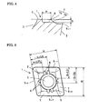
- Figure 1 is a plan view showing an indexable insert according to a first embodiment of the invention.
- Figure 2 is an enlarged sectional view taken along line Y-Y in Fig. 1 .
- Figure 3 is an enlarged sectional view taken along line Z-Z in Fig. 1 .
- Figure 4 is a further enlarged sectional view showing a part of Fig. 2 .
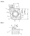
- Figure 5 is a plan view showing an indexable insert according to a second embodiment of the invention.
- Figure 6 is a plan view showing an indexable insert according to a third embodiment of the invention.
- Figure 7 is an enlarged sectional view of a primary portion showing an exemplary structure in which a recess penetrates to a center hole.
- Figure 8 is a sectional view showing a primary portion of a drill according to an embodiment of the invention.
- Figure 9 is a front elevation showing the drill in Fig. 8 .
- Figure 10 is a simplified illustration showing the arrangement of a peripheral cutting edge of the drill in Fig. 8 .
- Figure 11 is a simplified illustration showing the arrangement of a center cutting edge of the drill in Fig. 8 .
- Figure 12 is a schematic illustration showing the contact state of a chip to the recess.
- Figure 13 is a comparative diagram of thrust loads measured through performance evaluation test.
- FIG. 1 to 13 show an indexable insert according to a first embodiment of the invention
- Figure 5 shows a second embodiment
- Figure 6 shows a third embodiment.
- Any of the exemplary indexable inserts 1 is a positive insert having a parallelogram shape in plan view.
- Cutting edges 6 are defined by four ridges where the upper face 2, that is, the four sides at the periphery of an upper face 2, intersect with flanks 3 and 4 at an acute angle (see Figs. 2 and 3 ).
- the cutting edges 6 contain two pairs of cutting edges, each pair being arranged parallel to each other.
- One pair of cutting edges 6 -1 (subfix is applied to discriminate between the two kinds of cutting edges) serve as peripheral cutting edges of a drill.
- the other pair of cutting edges 6 -2 serve as center cutting edges of the drill.
- the indexable insert 1 should preferably have the two cutting edges 6 -1 serving as the peripheral cutting edges and the two cutting edges 6 -2 serving as the center cutting edges of the drill to balance the kinds of the inserts 1.
- the shape of the insert 1 does not have to be a parallelogram, and may be a polygon.
- the indexable insert 1 has a center hole 5 for its attachment.
- a chip breaker 7 is continuously arranged at the upper face 2 to longitudinally extend along the entire cutting edge 6.
- a recess 8 is provided respectively at a longitudinally intermediate portion of the chip breaker 7.
- a flat land 9 is formed by bulging a part of the upper face 2.
- the illustrated chip breaker 7 is a combination of a breaker wall 7a curved upward to a position higher than the position of the cutting edge 6, and a breaker groove in which the rake face (upper face 2) near the cutting edge 6 is curved downward so that the groove is partially located lower than the position of the cutting edge 6.
- the chip breaker 7 has a width W ranging from 0.5 to 2.0 mm as in examples. However, the width W is not limited thereto, and a proper value may be selected in accordance with the cutting conditions and the material of a workpiece. As shown in Figs. 2 and 3 , an end 7b of the chip breaker 7 near the cutting edge 6 may be located at a position higher than the position of the cutting edge 6. Hence, chips likely collide with the chip breaker 7, providing efficient chip disposability
- the recess 8 has a retracted distance H of 0.2 mm or greater, from the end 7b near the cutting edge 6 to the center of the insert 1. If a distance D shown in Fig. 1 from the end 7b of the chip breaker 7 near the cutting edge 6 to the center hole 5 is 0.2 mm or smaller, the retracted distance H cannot satisfy the condition. Thus, as shown in Fig. 7 , the recess 8 penetrates to the center hole 5. Also, if a distance (distance E in Fig. 1 ) from an end of the recess 8 near the center hole 5 to the center hole 5 is 0.5 mm or smaller, it is difficult to keep the strength of a portion (portion F in Fig.
- the portion may easily crack during usage or manufacturing of the insert 1. To avoid this, the recess 8 may penetrate to the center hole 5. If the recess 8 is retracted from the end 7b of the chip breaker 7 near the cutting edge 6 to the center of the insert 1 by 0.2 mm or greater, chips are discharged without coming into contact with the bottom of the recess 8 and the end thereof near the center hole 5. Thus, the chip flow-out resistance can be efficiently reduced.
- the recesses 8 may be composed of only those not reaching the center hole 5, or only those penetrating to the center hole 5.
- the recesses 8 may be composed of those not reaching the center hole 5, and those penetrating to the center hole 5.
- a plurality of recesses 8 may be provided at positions with a proper interval along each cutting edge 6.
- the recess 8 may be arranged in an area distant from an insert edge by 25% to 60% of an insert width.
- the insert width mentioned above is an inert width A defined by a dimension between the cutting edges 6. 2
- the insert edge is an edge of the part substantially serving as the peripheral cutting edge during the usage of the insert 1.
- the insert width mentioned above is an inert width B defined by a dimension between the cutting edges 6 -1
- the insert edge is an edge of the part substantially serving as the center cutting edge during the usage of the insert 1.
- the exemplary insert 1 uses one of adjacent sides (cutting edges) as the peripheral cutting edge of the drill, and uses the other as the center cutting edge.
- the overlap amount between the locus of the peripheral cutting edge and that of the center cutting edge is varied to accommodate variation in the diameter of the drill.
- the recess 8 should be preferably arranged at the area distant from the insert edge by 25% to 60% of the insert width.
- the recess 8 may have a depth G (see Figs. 2 and 3 ) of 0.1 mm or greater.
- a depth G is 0.1 mm or greater, a clearance is formed between the bottom of the recess 8 and the chips, the recess can reliably and efficiently reduce the cutting resistance. If the width C of the recess 8 is too large, the chips likely come into contact with the bottom of the recess 8. Hence, a proper value is obtained in accordance with the cutting conditions and the material of a workpiece.
- the chip disposability required for use under typical cutting conditions can be provided.
- the typical cutting conditions mentioned here contain a cutting speed ranging from 70 to 400 m/min, and a feed per revolution of 0.05 mm/rev or higher. If the feed per revolution is 0.05 mm or lower, the chips produced may be so thin that the recess 8 may not efficiently reduce the contact area.
- Figures 8 and 9 show an exemplary drill of the invention, having the above-described indexable inserts 1 to define the cutting edges 6 thereof.
- the drill has a drill body 11 with two flutes 12 at its periphery
- the drill body 11 has at a tip thereof insert seats 13 at positions rotated by about 180 degrees.
- the two insert seats 13 are located with different installation distances to the drill center O.
- the indexable inserts 1 of the invention are detachably attached to the insert seats 13 with clamp screws 14.
- the two indexable inserts 1 are attached in a manner that the upper faces 2 serve as rake faces.
- One of the indexable inserts 1 near the periphery of the drill body 11 is arranged such that one of acute corners is located at the outermost periphery and the farthermost edge as shown in Fig. 10 .
- the cutting edge 6 -1 of the insert 1 defines the peripheral cutting edge of the drill at an angle ⁇ to a line perpendicular to the axis of the drill.
- the other of the indexable inserts 1 is arranged such that one of obtuse corners is located near the periphery while one of acute corners is located at a position exceeding the drill center as shown in Fig. 11 .
- the cutting edge 6 -2 sloping in the same direction as the peripheral cutting edge of the insert 1 defines the center cutting edge of the drill.
- the peripheral cutting edge of the drill defined by the cutting edge 6 -1 and the center cutting edge of the drill defined by the cutting edge 6 -2 share a cutting area extending from the drill center to the periphery of the drill to perform cutting. Chips produced during cutting enter the recess 8 as shown in Fig. 12 .
- the size of the recess 8 is determined so that a clearance is provided between the bottom of the recess 8 and a chip 10 (the optimum size of the recess 8 may vary in accordance with the cutting conditions and the material of a workpiece), whereby the contact area of the chips to the insert 1 and the cutting resistance can be reduced.
- Evaluation test was performed to check the reduction efficiency of the cutting resistance with or without the recess formed in the chip breaker.
- the test was performed using an insert having the shape of Fig. 1 in which the recess as the feature of the invention was formed at the longitudinally intermediate portion of the chip breaker, and using an insert having a shape similar to Fig. 1 , but having no recess.
- a drill having the inserts, in which the recesses were provided at the chip breakers, to define the peripheral cutting edge and the center cutting edge was prepared.
- a workpiece of S50C and a workpiece of SS400 were machined with the drill under the same conditions as those of Example 1.
- the retracted distance H of the recess 8 shown in Figs. 2 and 3 from the end 7b of the chip breaker near the cutting edge to the center of the insert, and the depth G of the recess 8 were varied.
- whether or not the recess 8 could provide the reduction efficiency of the cutting resistance (thrust load) was checked. The result is shown in Tables I and II. Table I Reduction efficiency of thrust.
- the retracted distance H of the recess 8 from the end of the chip breaker near the cutting edge to the center of the insert was 0.2 mm or smaller, the advantageous effect by the recess was not provided depending on the material of the workpiece.
- the chips produced had a step portion with a height of about 0.1 mm at maximum at the portion entered the recess.
- the retracted distance H of the end of the recess 8 near the center hole 5 from the end of the chip breaker near the cutting edge was determined to 0.2 mm, as a dimension that allows the step portion of the chip not to come into contact with the end of the recess 8 near the center hole.
- the depth G of the recess 8 may be 0.1 mm or greater according to the same reason, and the test result also supports the value.
Landscapes
- Engineering & Computer Science (AREA)
- Mechanical Engineering (AREA)
- Drilling Tools (AREA)
Priority Applications (1)
| Application Number | Priority Date | Filing Date | Title |
|---|---|---|---|
| EP13152378.9A EP2586550B1 (de) | 2007-03-07 | 2008-02-29 | Wendeschneidplatte und Bohrer damit |
Applications Claiming Priority (1)
| Application Number | Priority Date | Filing Date | Title |
|---|---|---|---|
| JP2007057038A JP4528796B2 (ja) | 2007-03-07 | 2007-03-07 | スローアウェイチップを用いたドリル |
Related Child Applications (1)
| Application Number | Title | Priority Date | Filing Date |
|---|---|---|---|
| EP13152378.9A Division EP2586550B1 (de) | 2007-03-07 | 2008-02-29 | Wendeschneidplatte und Bohrer damit |
Publications (2)
| Publication Number | Publication Date |
|---|---|
| EP1967306A2 true EP1967306A2 (de) | 2008-09-10 |
| EP1967306A3 EP1967306A3 (de) | 2010-04-21 |
Family
ID=39493404
Family Applications (2)
| Application Number | Title | Priority Date | Filing Date |
|---|---|---|---|
| EP13152378.9A Active EP2586550B1 (de) | 2007-03-07 | 2008-02-29 | Wendeschneidplatte und Bohrer damit |
| EP08003819A Withdrawn EP1967306A3 (de) | 2007-03-07 | 2008-02-29 | Wendeschneidplatte und Bohrer damit |
Family Applications Before (1)
| Application Number | Title | Priority Date | Filing Date |
|---|---|---|---|
| EP13152378.9A Active EP2586550B1 (de) | 2007-03-07 | 2008-02-29 | Wendeschneidplatte und Bohrer damit |
Country Status (6)
| Country | Link |
|---|---|
| US (1) | US8197163B2 (de) |
| EP (2) | EP2586550B1 (de) |
| JP (1) | JP4528796B2 (de) |
| CN (1) | CN101259544B (de) |
| ES (1) | ES2564945T3 (de) |
| IL (1) | IL189902A (de) |
Cited By (1)
| Publication number | Priority date | Publication date | Assignee | Title |
|---|---|---|---|---|
| CN116532692A (zh) * | 2023-06-21 | 2023-08-04 | 浙江欣兴工具股份有限公司 | 一种具有高定位能力的刀片组合及可转位钻头 |
Families Citing this family (19)
| Publication number | Priority date | Publication date | Assignee | Title |
|---|---|---|---|---|
| JP5081229B2 (ja) * | 2007-03-27 | 2012-11-28 | 京セラ株式会社 | 切削インサートおよび切削工具、並びにそれを用いた被削材の切削方法 |
| KR101059288B1 (ko) * | 2008-11-18 | 2011-08-24 | 대구텍 유한회사 | 드릴용 절삭공구 |
| DE102012014092B4 (de) | 2011-07-22 | 2020-12-17 | Kennametal India Ltd. | Indexierbarer Bohreinsatz sowie Bohrkörper mit indexierbarem Bohreinsatz |
| US9370825B2 (en) | 2011-07-22 | 2016-06-21 | Kennametal India Limited | Indexable drill insert |
| DE102012012980B4 (de) | 2011-07-22 | 2019-10-17 | Kennametal India Ltd. | Bohrwerkzeug |
| JP5823840B2 (ja) * | 2011-11-30 | 2015-11-25 | 富士重工業株式会社 | ドリルおよび切削加工物の製造方法 |
| US8858130B2 (en) * | 2012-04-24 | 2014-10-14 | Kennametal Inc. | Indexable circular cutting insert |
| CN103447591B (zh) | 2012-05-28 | 2020-02-28 | 钴碳化钨硬质合金印度有限公司 | 四角形的可转位的钻头镶片 |
| WO2014116571A1 (en) | 2013-01-23 | 2014-07-31 | Kennametal India Limited | Indexable drill insert and rotary cutting tool employing same |
| KR101582390B1 (ko) * | 2013-12-23 | 2016-01-04 | 창 신-티엔 | 일회용 조각 칼날 |
| CN104439317B (zh) * | 2014-09-18 | 2018-10-09 | 厦门金鹭特种合金有限公司 | 一种具有多种刃口组合的切削刀片 |
| CN104475827B (zh) * | 2014-11-20 | 2017-04-05 | 厦门金鹭特种合金有限公司 | 一种四幅拳形刃分层钻削专用刀片 |
| KR102386942B1 (ko) | 2017-08-23 | 2022-04-14 | 대구텍 유한책임회사 | 드릴용 절삭 인서트 |
| WO2019220778A1 (ja) | 2018-05-16 | 2019-11-21 | 住友電工ハードメタル株式会社 | ドリル用切削インサートおよびドリル |
| CN112077369A (zh) | 2019-06-13 | 2020-12-15 | 肯纳金属印度有限公司 | 可转位钻头刀片 |
| CN112077370B (zh) | 2019-06-13 | 2024-10-01 | 肯纳金属印度有限公司 | 可转位钻头刀片 |
| CN112388033B (zh) | 2019-08-14 | 2024-10-25 | 肯纳金属印度有限公司 | 可转位钻头刀片 |
| EP4209297A4 (de) * | 2020-09-02 | 2023-10-11 | Sumitomo Electric Hardmetal Corp. | Schneideinsatz für ein drehschneidwerkzeug und drehschneidwerkzeug |
| CN115703157A (zh) | 2021-08-17 | 2023-02-17 | 肯纳金属印度有限公司 | 具有冷却剂系统的可转位钻头组件 |
Citations (2)
| Publication number | Priority date | Publication date | Assignee | Title |
|---|---|---|---|---|
| JP2582812Y2 (ja) | 1991-09-30 | 1998-10-15 | 東芝タンガロイ株式会社 | ドリル用のスローアウェイチップ |
| JP2002307221A (ja) | 2001-04-16 | 2002-10-23 | Toshiba Tungaloy Co Ltd | スローアウェイ式ドリル用の切刃チップ |
Family Cites Families (21)
| Publication number | Priority date | Publication date | Assignee | Title |
|---|---|---|---|---|
| DE7721135U1 (de) * | 1977-07-06 | 1979-01-04 | Komet Stahlhalter- Und Werkzeugfabrik Robert Breuning Gmbh, 7122 Besigheim | Bohrwerkzeug fuer bohrungen in metallvollmaterial von werkstuecken |
| JPS5464384U (de) * | 1977-10-17 | 1979-05-07 | ||
| JPS5934915U (ja) | 1982-08-31 | 1984-03-05 | 三菱マテリアル株式会社 | スロ−アウエイ式切削工具 |
| US4507024A (en) * | 1982-09-30 | 1985-03-26 | Gte Valeron Corporation | Cutting insert with chip control |
| JPH0672819B2 (ja) | 1987-09-29 | 1994-09-14 | 松下電器産業株式会社 | 温熱検知装置 |
| IL100703A (en) * | 1992-01-20 | 1995-01-24 | Iscar Ltd | Cutting insert having a circular cutting edge with a chip former |
| JP3237372B2 (ja) * | 1994-03-07 | 2001-12-10 | 三菱マテリアル株式会社 | スローアウェイチップ |
| US5791833A (en) * | 1994-12-29 | 1998-08-11 | Kennametal Inc. | Cutting insert having a chipbreaker for thin chips |
| US5807031A (en) * | 1995-03-10 | 1998-09-15 | Mitsubishi Materials Corp. | Throw-away tip and throw-away type cutter |
| JPH1086014A (ja) * | 1996-09-11 | 1998-04-07 | Hitachi Tool Eng Ltd | フライス用ブレーカ付きスローアウェイチップ |
| CN1203841A (zh) | 1997-06-26 | 1999-01-06 | 沃尔特公开股份有限公司 | 带矩形刀片的钻孔工具 |
| JP2933079B1 (ja) | 1998-03-30 | 1999-08-09 | 住友電気工業株式会社 | スローアウエイチップ及び正面フライス |
| US6217264B1 (en) * | 1998-05-30 | 2001-04-17 | Korloy, Inc. | Cutting insert having an improved chip breaker |
| JP4475723B2 (ja) * | 2000-02-25 | 2010-06-09 | 株式会社タンガロイ | スローアウェイ式ドリル用チップ |
| JP2003039228A (ja) | 2001-07-25 | 2003-02-12 | Mitsubishi Materials Corp | スローアウェイチップ |
| SE525241C2 (sv) * | 2002-05-29 | 2005-01-11 | Sandvik Ab | Borrverktygsats, borrverktyg samt indexerbart borrskär härför |
| SE525712C2 (sv) * | 2002-06-26 | 2005-04-12 | Sandvik Ab | Skär för borrar med spånbrytare |
| CN1539585A (zh) | 2003-10-28 | 2004-10-27 | 哈尔滨理工大学 | 车铣两用可转位圆刀片 |
| US6979153B1 (en) * | 2004-08-20 | 2005-12-27 | Sandvik Ab | Deep-grooving insert having stepped cutting edge |
| EP1904254B1 (de) * | 2005-07-05 | 2013-12-25 | Seco Tools AB | Schneideinsatz zum drehen mit einer aussparung, die platz für einen kühlstrahl schaffen soll |
| JP6121766B2 (ja) | 2012-03-26 | 2017-04-26 | 東芝メディカルシステムズ株式会社 | 超音波診断装置、画像処理装置及び画像処理方法 |
-
2007
- 2007-03-07 JP JP2007057038A patent/JP4528796B2/ja active Active
-
2008
- 2008-02-29 EP EP13152378.9A patent/EP2586550B1/de active Active
- 2008-02-29 EP EP08003819A patent/EP1967306A3/de not_active Withdrawn
- 2008-02-29 ES ES13152378.9T patent/ES2564945T3/es active Active
- 2008-03-03 IL IL189902A patent/IL189902A/en active IP Right Grant
- 2008-03-07 US US12/044,529 patent/US8197163B2/en active Active
- 2008-03-07 CN CN200810007739XA patent/CN101259544B/zh active Active
Patent Citations (2)
| Publication number | Priority date | Publication date | Assignee | Title |
|---|---|---|---|---|
| JP2582812Y2 (ja) | 1991-09-30 | 1998-10-15 | 東芝タンガロイ株式会社 | ドリル用のスローアウェイチップ |
| JP2002307221A (ja) | 2001-04-16 | 2002-10-23 | Toshiba Tungaloy Co Ltd | スローアウェイ式ドリル用の切刃チップ |
Cited By (1)
| Publication number | Priority date | Publication date | Assignee | Title |
|---|---|---|---|---|
| CN116532692A (zh) * | 2023-06-21 | 2023-08-04 | 浙江欣兴工具股份有限公司 | 一种具有高定位能力的刀片组合及可转位钻头 |
Also Published As
| Publication number | Publication date |
|---|---|
| EP2586550B1 (de) | 2016-02-24 |
| EP2586550A3 (de) | 2013-06-05 |
| JP2008213124A (ja) | 2008-09-18 |
| ES2564945T3 (es) | 2016-03-30 |
| EP2586550A2 (de) | 2013-05-01 |
| CN101259544A (zh) | 2008-09-10 |
| IL189902A (en) | 2014-01-30 |
| US8197163B2 (en) | 2012-06-12 |
| CN101259544B (zh) | 2011-09-14 |
| JP4528796B2 (ja) | 2010-08-18 |
| US20080219791A1 (en) | 2008-09-11 |
| EP1967306A3 (de) | 2010-04-21 |
Similar Documents
| Publication | Publication Date | Title |
|---|---|---|
| EP2586550B1 (de) | Wendeschneidplatte und Bohrer damit | |
| JP5369185B2 (ja) | 切削インサート及び切削工具、並びにそれを用いた切削加工物の製造方法 | |
| EP2403675B1 (de) | Schneideeinsatz mit eingelassener einsatzhaltefläche und schneidewerkzeug damit | |
| US9555488B2 (en) | Milling insert | |
| US8449226B2 (en) | Throw-away cutting insert and cutting tool with replaceable cutting edge using the same | |
| US8696263B2 (en) | Cutting insert and cutting edge replaceable cutting tool | |
| KR101380884B1 (ko) | 양면형 절삭 인서트 | |
| US8545141B2 (en) | Twist drill | |
| US5544984A (en) | Cutting insert with twisted chip surface | |
| US5147158A (en) | Cutting insert | |
| JP2850893B2 (ja) | スローアウェイチップ及びスローアウェイ式ドリル | |
| JP4063338B2 (ja) | 切削加工用カッティングインサート | |
| KR20010085913A (ko) | 드릴용 커팅 인써트 | |
| US20100329804A1 (en) | Cutting Insert for Drill, Drill, and Method of Cutting Using the Same | |
| US9370833B2 (en) | Cutting insert and indexable rotary cutting tool | |
| US11504780B2 (en) | Cutting tool | |
| JP4627849B2 (ja) | スローアウェイチップ | |
| US20070258778A1 (en) | Cutting insert with recessed corners | |
| WO2011062245A1 (ja) | 切削インサートおよび切削工具 | |
| US20160193668A1 (en) | Insert for drill and cutting blade replacement-type drill | |
| JPH10138033A (ja) | スローアウェイチップ | |
| JP4738391B2 (ja) | スローアウェイチップ及びそれを用いた回転工具 | |
| JP2006055915A (ja) | プリント配線板加工用の小径ドリル | |
| JP3518315B2 (ja) | スローアウェイチップおよび該スローアウェイチップを装着したスローアウェイ式穴明け工具 | |
| KR102855563B1 (ko) | 절삭 인서트 및 이를 포함하는 절삭 공구 |
Legal Events
| Date | Code | Title | Description |
|---|---|---|---|
| PUAI | Public reference made under article 153(3) epc to a published international application that has entered the european phase |
Free format text: ORIGINAL CODE: 0009012 |
|
| AK | Designated contracting states |
Kind code of ref document: A2 Designated state(s): AT BE BG CH CY CZ DE DK EE ES FI FR GB GR HR HU IE IS IT LI LT LU LV MC MT NL NO PL PT RO SE SI SK TR |
|
| AX | Request for extension of the european patent |
Extension state: AL BA MK RS |
|
| PUAL | Search report despatched |
Free format text: ORIGINAL CODE: 0009013 |
|
| AK | Designated contracting states |
Kind code of ref document: A3 Designated state(s): AT BE BG CH CY CZ DE DK EE ES FI FR GB GR HR HU IE IS IT LI LT LU LV MC MT NL NO PL PT RO SE SI SK TR |
|
| AX | Request for extension of the european patent |
Extension state: AL BA MK RS |
|
| 17P | Request for examination filed |
Effective date: 20100722 |
|
| AKX | Designation fees paid |
Designated state(s): DE ES IT SE |
|
| 17Q | First examination report despatched |
Effective date: 20110311 |
|
| 18D | Application deemed to be withdrawn |
Effective date: 20131224 |
|
| STAA | Information on the status of an ep patent application or granted ep patent |
Free format text: STATUS: THE APPLICATION IS DEEMED TO BE WITHDRAWN |
|
| R18D | Application deemed to be withdrawn (corrected) |
Effective date: 20140103 |