EP1964749B1 - Schienenautoförderzug und Teile davon - Google Patents
Schienenautoförderzug und Teile davon Download PDFInfo
- Publication number
- EP1964749B1 EP1964749B1 EP08153749.0A EP08153749A EP1964749B1 EP 1964749 B1 EP1964749 B1 EP 1964749B1 EP 08153749 A EP08153749 A EP 08153749A EP 1964749 B1 EP1964749 B1 EP 1964749B1
- Authority
- EP
- European Patent Office
- Prior art keywords
- bearing
- bearing adapter
- sideframe
- truck
- pedestal
- Prior art date
- Legal status (The legal status is an assumption and is not a legal conclusion. Google has not performed a legal analysis and makes no representation as to the accuracy of the status listed.)
- Expired - Lifetime
Links
Images















Classifications
-
- B—PERFORMING OPERATIONS; TRANSPORTING
- B61—RAILWAYS
- B61F—RAIL VEHICLE SUSPENSIONS, e.g. UNDERFRAMES, BOGIES OR ARRANGEMENTS OF WHEEL AXLES; RAIL VEHICLES FOR USE ON TRACKS OF DIFFERENT WIDTH; PREVENTING DERAILING OF RAIL VEHICLES; WHEEL GUARDS, OBSTRUCTION REMOVERS OR THE LIKE FOR RAIL VEHICLES
- B61F3/00—Types of bogies
-
- B—PERFORMING OPERATIONS; TRANSPORTING
- B61—RAILWAYS
- B61F—RAIL VEHICLE SUSPENSIONS, e.g. UNDERFRAMES, BOGIES OR ARRANGEMENTS OF WHEEL AXLES; RAIL VEHICLES FOR USE ON TRACKS OF DIFFERENT WIDTH; PREVENTING DERAILING OF RAIL VEHICLES; WHEEL GUARDS, OBSTRUCTION REMOVERS OR THE LIKE FOR RAIL VEHICLES
- B61F5/00—Constructional details of bogies; Connections between bogies and vehicle underframes; Arrangements or devices for adjusting or allowing self-adjustment of wheel axles or bogies when rounding curves
- B61F5/50—Other details
-
- B—PERFORMING OPERATIONS; TRANSPORTING
- B61—RAILWAYS
- B61F—RAIL VEHICLE SUSPENSIONS, e.g. UNDERFRAMES, BOGIES OR ARRANGEMENTS OF WHEEL AXLES; RAIL VEHICLES FOR USE ON TRACKS OF DIFFERENT WIDTH; PREVENTING DERAILING OF RAIL VEHICLES; WHEEL GUARDS, OBSTRUCTION REMOVERS OR THE LIKE FOR RAIL VEHICLES
- B61F15/00—Axle-boxes
- B61F15/02—Axle-boxes with journal bearings
- B61F15/08—Axle-boxes with journal bearings the axle being slidable or tiltable in the bearings
-
- B—PERFORMING OPERATIONS; TRANSPORTING
- B61—RAILWAYS
- B61F—RAIL VEHICLE SUSPENSIONS, e.g. UNDERFRAMES, BOGIES OR ARRANGEMENTS OF WHEEL AXLES; RAIL VEHICLES FOR USE ON TRACKS OF DIFFERENT WIDTH; PREVENTING DERAILING OF RAIL VEHICLES; WHEEL GUARDS, OBSTRUCTION REMOVERS OR THE LIKE FOR RAIL VEHICLES
- B61F3/00—Types of bogies
- B61F3/02—Types of bogies with more than one axle
-
- B—PERFORMING OPERATIONS; TRANSPORTING
- B61—RAILWAYS
- B61F—RAIL VEHICLE SUSPENSIONS, e.g. UNDERFRAMES, BOGIES OR ARRANGEMENTS OF WHEEL AXLES; RAIL VEHICLES FOR USE ON TRACKS OF DIFFERENT WIDTH; PREVENTING DERAILING OF RAIL VEHICLES; WHEEL GUARDS, OBSTRUCTION REMOVERS OR THE LIKE FOR RAIL VEHICLES
- B61F5/00—Constructional details of bogies; Connections between bogies and vehicle underframes; Arrangements or devices for adjusting or allowing self-adjustment of wheel axles or bogies when rounding curves
- B61F5/02—Arrangements permitting limited transverse relative movements between vehicle underframe or bolster and bogie; Connections between underframes and bogies
- B61F5/04—Bolster supports or mountings
-
- B—PERFORMING OPERATIONS; TRANSPORTING
- B61—RAILWAYS
- B61F—RAIL VEHICLE SUSPENSIONS, e.g. UNDERFRAMES, BOGIES OR ARRANGEMENTS OF WHEEL AXLES; RAIL VEHICLES FOR USE ON TRACKS OF DIFFERENT WIDTH; PREVENTING DERAILING OF RAIL VEHICLES; WHEEL GUARDS, OBSTRUCTION REMOVERS OR THE LIKE FOR RAIL VEHICLES
- B61F5/00—Constructional details of bogies; Connections between bogies and vehicle underframes; Arrangements or devices for adjusting or allowing self-adjustment of wheel axles or bogies when rounding curves
- B61F5/02—Arrangements permitting limited transverse relative movements between vehicle underframe or bolster and bogie; Connections between underframes and bogies
- B61F5/04—Bolster supports or mountings
- B61F5/12—Bolster supports or mountings incorporating dampers
-
- B—PERFORMING OPERATIONS; TRANSPORTING
- B61—RAILWAYS
- B61F—RAIL VEHICLE SUSPENSIONS, e.g. UNDERFRAMES, BOGIES OR ARRANGEMENTS OF WHEEL AXLES; RAIL VEHICLES FOR USE ON TRACKS OF DIFFERENT WIDTH; PREVENTING DERAILING OF RAIL VEHICLES; WHEEL GUARDS, OBSTRUCTION REMOVERS OR THE LIKE FOR RAIL VEHICLES
- B61F5/00—Constructional details of bogies; Connections between bogies and vehicle underframes; Arrangements or devices for adjusting or allowing self-adjustment of wheel axles or bogies when rounding curves
- B61F5/02—Arrangements permitting limited transverse relative movements between vehicle underframe or bolster and bogie; Connections between underframes and bogies
- B61F5/04—Bolster supports or mountings
- B61F5/12—Bolster supports or mountings incorporating dampers
- B61F5/122—Bolster supports or mountings incorporating dampers with friction surfaces
-
- B—PERFORMING OPERATIONS; TRANSPORTING
- B61—RAILWAYS
- B61F—RAIL VEHICLE SUSPENSIONS, e.g. UNDERFRAMES, BOGIES OR ARRANGEMENTS OF WHEEL AXLES; RAIL VEHICLES FOR USE ON TRACKS OF DIFFERENT WIDTH; PREVENTING DERAILING OF RAIL VEHICLES; WHEEL GUARDS, OBSTRUCTION REMOVERS OR THE LIKE FOR RAIL VEHICLES
- B61F5/00—Constructional details of bogies; Connections between bogies and vehicle underframes; Arrangements or devices for adjusting or allowing self-adjustment of wheel axles or bogies when rounding curves
- B61F5/02—Arrangements permitting limited transverse relative movements between vehicle underframe or bolster and bogie; Connections between underframes and bogies
- B61F5/14—Side bearings
-
- B—PERFORMING OPERATIONS; TRANSPORTING
- B61—RAILWAYS
- B61F—RAIL VEHICLE SUSPENSIONS, e.g. UNDERFRAMES, BOGIES OR ARRANGEMENTS OF WHEEL AXLES; RAIL VEHICLES FOR USE ON TRACKS OF DIFFERENT WIDTH; PREVENTING DERAILING OF RAIL VEHICLES; WHEEL GUARDS, OBSTRUCTION REMOVERS OR THE LIKE FOR RAIL VEHICLES
- B61F5/00—Constructional details of bogies; Connections between bogies and vehicle underframes; Arrangements or devices for adjusting or allowing self-adjustment of wheel axles or bogies when rounding curves
- B61F5/26—Mounting or securing axle-boxes in vehicle or bogie underframes
-
- B—PERFORMING OPERATIONS; TRANSPORTING
- B61—RAILWAYS
- B61F—RAIL VEHICLE SUSPENSIONS, e.g. UNDERFRAMES, BOGIES OR ARRANGEMENTS OF WHEEL AXLES; RAIL VEHICLES FOR USE ON TRACKS OF DIFFERENT WIDTH; PREVENTING DERAILING OF RAIL VEHICLES; WHEEL GUARDS, OBSTRUCTION REMOVERS OR THE LIKE FOR RAIL VEHICLES
- B61F5/00—Constructional details of bogies; Connections between bogies and vehicle underframes; Arrangements or devices for adjusting or allowing self-adjustment of wheel axles or bogies when rounding curves
- B61F5/26—Mounting or securing axle-boxes in vehicle or bogie underframes
- B61F5/28—Axle-boxes integral with, or directly secured to, vehicle or bogie underframes
-
- B—PERFORMING OPERATIONS; TRANSPORTING
- B61—RAILWAYS
- B61F—RAIL VEHICLE SUSPENSIONS, e.g. UNDERFRAMES, BOGIES OR ARRANGEMENTS OF WHEEL AXLES; RAIL VEHICLES FOR USE ON TRACKS OF DIFFERENT WIDTH; PREVENTING DERAILING OF RAIL VEHICLES; WHEEL GUARDS, OBSTRUCTION REMOVERS OR THE LIKE FOR RAIL VEHICLES
- B61F5/00—Constructional details of bogies; Connections between bogies and vehicle underframes; Arrangements or devices for adjusting or allowing self-adjustment of wheel axles or bogies when rounding curves
- B61F5/26—Mounting or securing axle-boxes in vehicle or bogie underframes
- B61F5/30—Axle-boxes mounted for movement under spring control in vehicle or bogie underframes
-
- B—PERFORMING OPERATIONS; TRANSPORTING
- B61—RAILWAYS
- B61F—RAIL VEHICLE SUSPENSIONS, e.g. UNDERFRAMES, BOGIES OR ARRANGEMENTS OF WHEEL AXLES; RAIL VEHICLES FOR USE ON TRACKS OF DIFFERENT WIDTH; PREVENTING DERAILING OF RAIL VEHICLES; WHEEL GUARDS, OBSTRUCTION REMOVERS OR THE LIKE FOR RAIL VEHICLES
- B61F5/00—Constructional details of bogies; Connections between bogies and vehicle underframes; Arrangements or devices for adjusting or allowing self-adjustment of wheel axles or bogies when rounding curves
- B61F5/26—Mounting or securing axle-boxes in vehicle or bogie underframes
- B61F5/30—Axle-boxes mounted for movement under spring control in vehicle or bogie underframes
- B61F5/308—Axle-boxes mounted for movement under spring control in vehicle or bogie underframes incorporating damping devices
-
- B—PERFORMING OPERATIONS; TRANSPORTING
- B61—RAILWAYS
- B61F—RAIL VEHICLE SUSPENSIONS, e.g. UNDERFRAMES, BOGIES OR ARRANGEMENTS OF WHEEL AXLES; RAIL VEHICLES FOR USE ON TRACKS OF DIFFERENT WIDTH; PREVENTING DERAILING OF RAIL VEHICLES; WHEEL GUARDS, OBSTRUCTION REMOVERS OR THE LIKE FOR RAIL VEHICLES
- B61F5/00—Constructional details of bogies; Connections between bogies and vehicle underframes; Arrangements or devices for adjusting or allowing self-adjustment of wheel axles or bogies when rounding curves
- B61F5/38—Arrangements or devices for adjusting or allowing self- adjustment of wheel axles or bogies when rounding curves, e.g. sliding axles, swinging axles
-
- B—PERFORMING OPERATIONS; TRANSPORTING
- B61—RAILWAYS
- B61F—RAIL VEHICLE SUSPENSIONS, e.g. UNDERFRAMES, BOGIES OR ARRANGEMENTS OF WHEEL AXLES; RAIL VEHICLES FOR USE ON TRACKS OF DIFFERENT WIDTH; PREVENTING DERAILING OF RAIL VEHICLES; WHEEL GUARDS, OBSTRUCTION REMOVERS OR THE LIKE FOR RAIL VEHICLES
- B61F5/00—Constructional details of bogies; Connections between bogies and vehicle underframes; Arrangements or devices for adjusting or allowing self-adjustment of wheel axles or bogies when rounding curves
- B61F5/38—Arrangements or devices for adjusting or allowing self- adjustment of wheel axles or bogies when rounding curves, e.g. sliding axles, swinging axles
- B61F5/40—Bogies with side frames mounted for longitudinal relative movements
Definitions
- This invention relates to the field of rail road cars, and, more particularly, to the field of three piece rail road car trucks for rail road cars.
- Three piece trucks Rail road cars in North America commonly employ double axle swivelling trucks known as "three piece trucks” to permit them to roll along a set of rails.
- the three piece terminology refers to a truck bolster and pair of first and second sideframes.
- the truck bolster extends cross-wise relative to the sideframes, with the ends of the truck bolster protruding through the sideframe windows.
- Forces are transmitted between the truck bolster and the sideframes by spring groups mounted in spring seats in the sideframes.
- the sideframes carry forces to the sideframe pedestals.
- the pedestals seat on bearing adapters, whence forces are carried in turn into the bearings, the axle, the wheels, and finally into the tracks.
- Ride quality can be judged on a number of different criteria. There is longitudinal ride quality, where, often, the limiting condition is the maximum expected longitudinal acceleration experienced during humping orflat switching, or slack run-in and run-out. There is vertical ride quality, for which vertical force transmission through the suspension is the key determinant. There is lateral ride quality, which relates to the lateral response of the suspension.
- Lozenging, or parallelogramming is non-square deformation of the truck bolster relative to the sideframes of the truck as seen from above.
- Self steering may tend to be desirable since it may reduce drag and may tend to reduce wear to both the wheels and the track,and may give a smoother overall ride.
- the present invention in its various aspects provides a self-steering rolling contact rocker fitting that is part of a sideframe pedestal to axle bearing interface assembly mounted between a wheelset and a sideframe of a rail road freight car truck, said rolling contact rocker fitting having a rolling contact rocking surface that has a longitudinal direction curvature, whereby the rolling contact rocker fitting is operable to rock lengthwise relative to the sideframe.
- the invention may also comprise:
- the invention may comprise a sideframe pedestal to axle bearing interface assembly of a three piece rail road car truck, said interface assembly having rolling contact rocker fittings operable to rock both laterally and longitudinally.
- the invention may comprise the sideframe pedestal to axle bearing interface assembly wherein said assembly includes at least one rocker element and a mating element, said rocker element including said rocking surface, the rocker and mating element being in rolling point contact with said mating element.
- the invention may comprise a rail road car truck wheelset-to-sideframe interface assembly, said interface assembly comprising:
- the invention may comprise the sideframe pedestal to axle bearing interface assembly wherein said assembly includes an auxiliary centering member that urges said fittings to a centered condition.
- the invention may comprise the sideframe pedestal to axle bearing interface assembly wherein said assembly includes an elastomeric member, said bearing adapter has first and second end walls; said elastomeric member has a first portion seated adjacent to said first end wall, and a second portion at least partially overlying said bearing adapter; and said second portion of said elastomeric member having a relief formed therein that accommodates rocking engagement of said bearing adapter with said pedestal seat.
- the invention may comprise the sideframe pedestal to axle bearing interface assembly wherein said interface assemblies each include a bearing adapter that seats on a roller bearing having first and second axially spaced apart roller bearing races enclosed within a casing; said bearing adapter has an underside and first and second arches engaged with first and second end regions of the bearing casing; said underside has an apex and a land array engaging the casing, said land array extending between the arches and being relieved at locations along said apex corresponding to locations of the bearing races.
- said interface assemblies each include a bearing adapter that seats on a roller bearing having first and second axially spaced apart roller bearing races enclosed within a casing; said bearing adapter has an underside and first and second arches engaged with first and second end regions of the bearing casing; said underside has an apex and a land array engaging the casing, said land array extending between the arches and being relieved at locations along said apex corresponding to locations of the bearing races.
- the invention may comprise a rail road car truck comprising:
- the invention may comprise the three piece rail road car truck wherein said truck is free of unsprung lateral cross-members between said sideframes.
- the invention may comprise the railroad car truck, wherein sideframes include first and second sideframes, and said bolster has first and second ends mounted to said first and second sideframes; said truck has first and second groups of dampers mounted to work between said bolster and said first and second sideframes, respectively; said first group including a first damper and a second damper, and said second damper being mounted more laterally outboard than said first damper.
- the invention may comprise the railroad car truck wherein said dampers have co-efficients of static friction and dynamic friction, and said co-efficients are within 20 % of each other and wherein at least one of the dampers has co-efficients of static friction and dynamic friction, and both of those co-efficients lie in the range of 0.1 to 0.4.
- the invention may comprise the railroad car truck wherein:
- the invention may comprise the rail road car truck wherein said first main spring group has an overall vertical spring rate kspring group, and the springs mounted under said first, second third and fourth dampers have a total vertical spring rate kdamper springs, and kdamper springs is greater than 20 % of kspring group, and wherein said first, second, third and fourth dampers include damper wedges, and said damper wedges have primary damper angles of greater than 35 degrees.
- the invention may comprise the railroad car truck wherein said truck has a rated load, said sideframes are mounted truck has a resistance to lateral perturbations having a first characteristic, ksideframe associated with lateral swinging of the sideframes, and a second characteristic, kspring shear, associated with lateral shear of the main spring groups; and, at said rated load ksideframe is softer than kspring shear.
- the invention may comprise the railroad car truck wherein said bolster has a range of lateral translation relative to said bolster and gibs limiting said range, said range being at least as 3 ⁇ 4 inches to either side of a neutral position.
- the invention may comprise the railroad car truck wherein said truck has dampers mounted to work between said bolster and said sideframes, and said dampers exert a first friction force FD when said bolster is moving in a downward direction relative to said sideframes, and a second friction force, FU when said bolster is moving in an upward direction relative to said sideframes; and a ratio of FD: FU, by magnitude, lies in the range of 2:3 to 3:2.
- the invention may comprise at least one self-steering apparatus fitting of a wheel bearing to sideframe pedestal interface combination of a rail road car truck, said self-steering apparatus fitting comprising at least one of:
- the invention may comprise at least one self-steering apparatus fitting, said fitting being one of:
- the invention may comprise a bearing adapter in combination with a rail road car truck wheelset bearing, the bearing having a pair of axially spaced apart, circumferentially extending bearing races contained within a casing, and the bearing adapter having at least one underside relief formed therein, said bearing adapter mating with said casing in use with said relief overlying top dead center of at least one of said bearing races.
- the invention may comprise a combination of a bearing adapter, a pedestal seat, and a resilient pad member for use with the bearing adapter; at least one of (a) said bearing adapter and (b) said pedestal seat including the fitting according to claim 1, wherein the bearing adapter and the pedestal seat have respective mutually engaged rolling contact surfaces, said resilient pad has a first portion that engages a first end of the bearing adapter, a second portion that engages a second end of the bearing adapter, and a medial portion between said first and second end portions, said medial portion accommodating mating engagement of the rocker members.
- the invention may comprise a bearing adapter, wherein said bearing adapter has a body seated on a bearing, and a second member mounted to said body, said second member including said rocker fitting, and said second member being made of a different material than said body of said bearing adapter.
- the longitudinal direction is defined as being coincident with the rolling direction of the rail road car, or rail road car unit, when located on tangent (that is, straight) track.
- the longitudinal direction is parallel to the center sill, and parallel to the side sills, if any.
- vertical, or upward and downward are terms that use top of rail, TOR, as a datum.
- lateral, or laterally outboard refers to a distance or orientation relative to the longitudinal centerline of the railroad car, or car unit.
- the term "longitudinally inboard”, or “longitudinally outboard” is a distance taken relative to a mid-span lateral section of the car, or car unit.
- Pitching motion is angular motion of a railcar unit about a horizontal axis perpendicular to the longitudinal direction.
- Yawing is angular motion about a vertical axis.
- Roll is angular motion about the longitudinal axis.
- This application refers to friction dampers for rail road car trucks, and multiple friction damper systems.
- damper arrangements There are several types of damper arrangements, some being shown at pp. 715 - 716 of the 1997 Car and Locomotive Cyclopedia , those pages being incorporated herein by reference. Double damper arrangements are shown and described US Patent Application Publication No. US 2003/0041772 A1, March 6, 2003 , entitled “Rail Road Freight Car With Damped Suspension", and also incorporated herein by reference.
- Each of the arrangements of dampers shown at pp. 715 to 716 of the 1997 Car and Locomotive Cyclopedia can be modified to employ a four cornered, double damper arrangement of inner and outer dampers in conformity with the principles of aspects of the present invention.
- each wedge may then have a generally triangular shape, one side of the triangle being, or having, a bearing face, a second side which might be termed the bottom, or base, forming a spring seat, and the third side being a sloped side or hypotenuse between the other two sides.
- the first side may tend to have a substantially planar bearing face for vertical sliding engagement against an opposed bearing face of one of the sideframe columns.
- the second face may not be a face, as such, but rather may have the form of a socket for receiving the upper end of one of the springs of a spring group.
- the third face, or hypotenuse may appear to be generally planar, it may tend to have a slight crown, having a radius of curvature of perhaps 60".
- the crown may extend along the slope and may also extend across the slope.
- the end faces of the wedges may be generally flat, and may have a coating, surface treatment, shim, or low friction pad to give a smooth sliding engagement with the sides of the bolster pocket, or with the adjacent side of another independently slidable damper wedge, as may be.
- the sideframe may tend to rotate, or pivot, through a small range of angular deflection about the end of the truck bolster to yield wheel load equalisation.
- the slight crown on the slope face of the damper may tend to accommodate this pivoting motion by allowing the damper to rock somewhat relative to the generally inclined face of the bolster pocket while the planar bearing face remains in planar contact with the wear plate of the sideframe column.
- the slope face may have a slight crown, for the purposes of this description it will be described as the slope face or as the hypotenuse, and will be considered to be a substantially flat face as a general approximation.
- wedges have a primary angle ⁇ , being the included angle between (a) the sloped damper pocket face mounted to the truck bolster, and (b) the side frame column face, as seen looking from the end of the bolster toward the truck center.
- a secondary angle may be defined in the plane of angle ⁇ , namely a plane perpendicular to the vertical longitudinal plane of the (undeflected) side frame, tilted from the vertical at the primary angle. That is, this plane is parallel to the (undeflected) long axis of the truck bolster, and taken as if sighting along the back side (hypotenuse) of the damper.
- the secondary angle ⁇ is defined as the lateral rake angle seen when looking at the damper parallel to the plane of angle ⁇ .
- the wedge forces acting on the secondary angle ⁇ may tend to urge the damper either inboard or outboard according to the angle chosen.
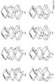
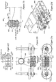
- Figures 1a and 1f provide examples of trucks 20 and 22 embodying an aspect of the invention.
- Trucks 20 and 22 of Figures 1a and 1f may have the same, or generally similar, features and similar construction, although they may differ in pendulum length, spring stiffness, wheelbase, window width and height, and damping arrangement. That is, truck 20 of Figure 1f may tend to have a longer wheelbase (from 73 inches to 86 inches, possibly between 80 - 84 inches for truck 20 , as opposed to a wheelbase of 63 - 73 inches for truck 22 ), may tend to have a main spring group having a softer vertical spring rate, and a four cornered damper group that may have different primary and secondary angles on the damper wedges.
- Truck 20 may have a 5 x 3 spring group arrangement, while truck 22 may have a 3 x3 arrangement. While either truck may be suitable for a variety of general purpose uses, truck 20 may be optimized for carrying relatively low density, high value lading, such as automobiles or consumer products, for example, whereas truck 22 may be optimized for carrying denser semi-finished industrial goods, such as might be carried in rail road freight cars for transporting rolls of paper.
- the various features of the two truck types may be interchanged, and are intended to be illustrative of a wide range of truck types. Notwithstanding possible differences in size, generally similar features are given the same part numbers.
- Trucks 20 and 22 are symmetrical about both their longitudinal and transverse, or lateral, centreline axes. In each case, where reference is made to a sideframe, it will be understood that the truck has first and second sideframes, first and second spring groups, and so on.
- Trucks 20 and 22 each have a truck bolster 24 and sideframes 26 .
- Each sideframe 26 has a generally rectangular window 28 that accommodates one of the ends 30 of the bolster 24 .
- the upper boundary of window 28 is defined by the sideframe arch, or compression member identified as top chord member 32, and the bottom of window 28 is defined by a tension member identified as bottom chord 34.
- the fore and aft vertical sides of window 28 are defined by sideframe columns 36.
- the ends of the tension member sweep up to meet the compression member.
- Each fitting 38 accommodates an upper fitting, which may be a rocker or a seat, as described and discussed below.
- Fitting 40 engages a mating fitting 42 of the upper surface of a bearing adapter 44.
- Bearing adapter 44 engages a bearing 46 mounted on one of the ends of one of the axles 48 of the truck adjacent one of the wheels 50.
- a fitting 40 is located in each of the fore and aft pedestal fittings 38, the fittings 40 being longitudinally aligned so the sideframe can swing sideways relative to the truck's rolling direction.
- the relationship of the mating fittings 40 and 42 is described at greater length below.
- the relationship of these fittings determines part of the overall relationship between an end of one of the axles of one of the wheelsets and the sideframe pedestal. That is, in determining the overall response, the degrees of freedom of the mounting of the axle end in the sideframe pedestal involve a dynamic interface across an assembly of parts, such as may be termed a wheelset to sideframe interface assembly, that may include the bearing, the bearing adapter, an elastomeric pad, if used, a rocker if used, and the pedestal seat mounted in the roof of the sideframe pedestal.
- a wheelset to sideframe interface assembly may include the bearing, the bearing adapter, an elastomeric pad, if used, a rocker if used, and the pedestal seat mounted in the roof of the sideframe pedestal.
- bearing 46 has a single degree of freedom, namely rotation about the wheelshaft axis
- analysis of the assembly can be focused on the bearing to pedestal seat interface assembly, or on the bearing adapter to pedestal seat interface assembly.
- items 40 and 42 are intended generically to represent the combination of features of a bearing adapter and pedestal seat assembly defining the interface between the roof of the sideframe pedestal and the bearing adapter, and the six degrees of freedom of motion at that interface, namely vertical, longitudinal and transverse translation (i.e., translation in the z, x, and y directions) and pitching, rolling, and yawing (i.e., rotational motion about the y, x, and z axes respectively) in response to dynamic inputs.
- vertical, longitudinal and transverse translation i.e., translation in the z, x, and y directions
- pitching, rolling, and yawing i.e., rotational motion about the y, x, and z axes respectively
- the bottom chord or tension member of sideframe 26 may have a basket plate, or lower spring seat 52 rigidly mounted thereto.
- trucks 22 may be free of unsprung lateral cross-bracing, whether in the nature of a transom or lateral rods, in the event that truck 22 is taken to represent a "swing motion" truck with a transom or other cross bracing
- the lower rocker platform of spring seat 52 may be mounted on a rocker, to permit lateral rocking relative to sideframe 26.
- Spring seat 52 may have retainers for engaging the springs 54 of a spring set, or spring group, 56, whether internal bosses, or a peripheral lip for discouraging the escape of the bottom ends of the springs.
- the spring group, or spring set 56 is captured between the distal end 30 of bolster 24 and spring seat 52, being placed under compression by the weight of the rail car body and lading that bears upon bolster 24 from above.
- Bolster 24 has double, inboard and outboard, bolster pockets 60, 62 on each face of the bolster at the outboard end (i.e., for a total of 8 bolster pockets per bolster, 4 at each end).
- Bolster pockets 60, 62 accommodate fore and aft pairs of first and second, laterally inboard and laterally outboard friction damper wedges 64, 66 and 68 , 70, respectively.
- Each bolster pocket 60, 62 has an inclined face, or damper seat 72, that mates with a similarly inclined hypotenuse face 74 of the damper wedge, 64, 66, 68 and 70 .
- wedges 64, 66 each sit over a first, inboard corner spring 76, 78, and wedges 68, 70 each sit over a second, outboard corner spring 80, 82 .
- Angled faces 74 of wedges 64, 66 and 68, 70 ride against the angled faces of respective seats 72.
- a middle end spring 96 bears on the underside of a land 98 located intermediate bolster pockets 60 and 62.
- the top ends of the central row of springs, 100 seat under the main central portion 102 of the end of bolster 24.
- each damper is individually sprung by one or another of the springs in the spring group.
- the static compression of the springs under the weight of the car body and lading tends to act as a spring loading to bias the damper to act along the slope of the bolster pocket to force the friction surface against the sideframe.
- Friction damping is provided when the vertical sliding faces 90 of the friction damper wedges 64, 66 and 68, 70 ride up and down on friction wear plates 92 mounted to the inwardly facing surfaces of sideframe columns 36.
- doubled dampers such as spaced apart pairs of dampers 64, 68 may tend to give a larger moment arm, as indicated by dimension "2M" in Figure 1d , for resisting parallelogram deformation of truck 22 more generally.
- Use of doubled dampers may yield a greater restorative "squaring" force to return the truck to a square orientation than for a single damper alone with the restorative bias, namely the squaring force, increasing with increasing deflection.
- the differential compression of one diagonal pair of springs e.g., inboard spring 76 and outboard spring 82 may be more pronouncedly compressed
- the other diagonal pair of springs e.g., inboard spring 78 and outboard spring 80 may be less pronouncedly compressed than springs 76 and 82
- This moment couple tends to rotate the sideframe in a direction to square the truck, (that is, in a position in which the bolster is perpendicular, or "square", to the sideframes).
- the truck is able to flex, and when it flexes the dampers co-operate in acting as biased members working between the bolster and the side frames to resist parallelogram, or lozenging, deformation of the side frame relative to the truck bolster and to urge the truck back to the non-deflected position.
- M R 4 k c Tan( ⁇ )Tan( ⁇ ) L , where ⁇ is the primary angle of the damper (generally illustrated as ⁇ herein), and k c is the vertical spring constant of the coil upon which the damper sits and is biased.
- dampers may be mounted over each of four corner positions.
- the portion of spring force acting under the damper wedges may be in the 25 - 50 % range for springs of equal stiffness. If not of equal stiffness, the portion of spring force acting under the dampers may be in the range of perhaps 20 % to 35 %.
- the coil groups can be of unequal stiffness if inner coils are used in some springs and not in others, or if springs of differing spring constant are used.
- an enhanced tendency to encourage squareness at the bolster to sideframe interface may tend to reduce reliance on squareness at the pedestal to wheelset axle interface.
- This may tend to provide an opportunity to employ a torsionally compliant (about the vertical axis) axle to pedestal interface assembly, and to permit a measure of self steering.
- the bearing plate namely wear plate 92 ( Figure 1a ) is significantly wider than the through thickness of the sideframes more generally, as measured, for example, at the pedestals, and may tend to be wider than has been conventionally common.
- This additional width corresponds to the additional overall damper span width measured fully across the damper pairs, plus lateral travel as noted above, typically allowing 1 1 ⁇ 2 (+/-) inches of lateral travel of the bolster relative to the sideframe to either side of the undeflected central position. That is, rather than having the width of one coil, plus allowance for travel, plate 92 may have the width of three coils, plus allowance to accommodate 1 1 ⁇ 2 (+/-) inches of travel to either side for a total, double amplitude travel of 3" (+/-).
- Bolster 24 has inboard and outboard gibs 106, 108 respectively, that bound the lateral motion of bolster 24 relative to sideframe columns 36.
- This motion allowance may be in the range of +/-1 1 ⁇ 8 to 1 3 ⁇ 4 in., and may be in the range of 1 3/16 to 1 9/16 in., and can be set, for example, at 1 1 ⁇ 2 in. or 1 1 ⁇ 4 in. of lateral travel to either side of a neutral, or centered, position when the sideframe is undeflected.
- truck 22 employs a spring group in a 3 x 3 arrangement, this is intended to be generic, and to represent a range of variations. They may represent 3 x 5, 2 x 4, 3:2:3 or 2:3:2 arrangement, or some other, and may include a hydraulic snubber, or such other arrangement of springs may be appropriate for the given service for the railcar for which the truck is intended.
- the rocking interface surface of the bearing adapter might have a crown, or a concave curvature, like a swing motion truck, by which a rolling contact on the rocker permits lateral swinging of the side frame.
- the bearing adapter to pedestal seat interface might also have a fore-and-aft curvature, whether a crown or a depression, and that, for a given vertical load, this crown or depression might tend to present a more or less linear resistance to deflection in the longitudinal direction, much as a spring or elastomeric pad might do.
- the vertical stiffness may be approximated as infinite (i.e. very large as compared to other stiffnesses); the longitudinal stiffness in translation at the point of contact can also be taken as infinite, the assumption being that the surfaces do not slip; the lateral stiffness in translation at the point of contact can be taken as infinite, again, provided the surfaces do not slip.
- the rotational stiffness about the vertical axis may be taken as zero or approximately zero.
- the angular stiffnesses about the longitudinal and transverse axes are non-trivial. The lateral angular stiffnesses may tend to determine the equivalent pendulum stiffnesses for the sideframe more generally.
- the stiffness of a pendulum is directly proportional to the weight on the pendulum.
- the drag on a rail car wheel, and the wear to the underlying track structure is a function of the weight borne by the wheel. For this reason, the desirability of self steering may be greatest for a fully laden car, and a pendulum may tend to maintain a general proportionality between the weight borne by the wheel and the stiffness of the self-steering mechanism as the lading increases.
- Truck performance may vary with the friction characteristics of the damper surfaces. Dampers have been used that have tended to employ dampers in which the dynamic and static coefficients of friction may have been significantly different, yielding a stick-slip phenomenon that may not have been entirely advantageous. It may be advantageous to combine the feature of a self-steering capability with dampers that have a reduced tendency to stick-slip operation.
- bearing adapters may be formed of relatively low cost materials, such as cast iron, in some embodiments an insert of a different material may be used for the rocker. Further it may be advantageous to employ a member that may tend to center the rocker on installation, and that may tend to perform an auxiliary centering function to tend to urge the rocker to operate from a desired minimum energy position.
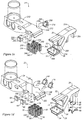
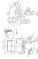
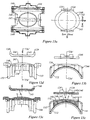
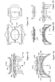
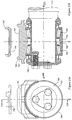
- FIGS 2a - 2g show an embodiment of bearing adapter and pedestal seat assembly.
- Bearing adapter 44 has a lower portion 112 that is formed to accommodate, and to seat upon, bearing 46, that is itself mounted on the end of a shaft, namely an end of axle 48.
- Bearing adapter 44 has an upper portion 114 that has a centrally located, upwardly protruding fitting in the nature of a male bearing adapter interface portion 116.
- a mating fitting, in the nature of a female rocker seat interface portion 118 is rigidly mounted within the roof 120 of the sideframe pedestal. To that end, laterally extending lugs 122 are mounted centrally with respect to pedestal roof 120.
- the upper fitting 40 has a body that may be in the form of a plate 126 having, along its longitudinally extending, lateral margins a set of upwardly extending lugs or ears, or tangs 124 separated by a notch, that bracket, and tightly engage lugs 122, thereby locating upper fitting 40 in position, with the back of the plate 126 of fitting 40 abutting the flat, load transfer face of roof 120.
- Upper fitting 40 may be a pedestal seat fitting with a hollowed out female bearing surface, namely portion 118.
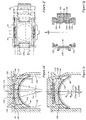
- Male portion 116 ( Figure 2d ) has been formed to have a generally upwardly facing surface 142 that has both a first curvature r 1 to permit rocking in the longitudinal direction, and a second curvature r 2 ( Figure 2c ) to permit rocking (i.e., swing motion of the sideframe) in the transverse direction.
- female portion 118 has a surface having a first radius of curvature R 1 in the longitudinal direction, and a second radius of curvature R 2 in the transverse direction. The engagement of r 1 with R 1 may tend to permit a rocking motion in the longitudinal direction, with resistance to rocking displacement being proportional to the weight on the wheel.
- the resistance to angular deflection is proportional to weight rather than being a fixed spring constant. This may tend to yield passive self-steering in both the light car and fully laden conditions.
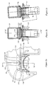
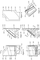
- Figures 2d and 2e show the centered, or at rest, non-deflected position of the longitudinal rocking elements.
- Figure 2e shows the rocking elements at their condition of maximum longitudinal deflection.
- Figure 2d represents a local, minimum potential energy condition for the system.
- Figure 2e represents a system in which the potential energy has been increased by virtue of the work done by force F acting longitudinally in the horizontal plane through the center of the axle and bearing, C B ., which will tend to yield an incremental increase in the height of the pedestal.
- the rocking motion may tend to raise the car, and thereby to increase its potential energy.
- the limit of travel in the longitudinal direction is reached when the end face 134 of bearing adapter 44 extending between corner abutments 132 , contacts one or another of travel limiting abutment faces 136 of the thrust blocks of jaws 130.
- the deflection may be measured either by the angular displacement of the axle centreline, ⁇ 1 , or by the angular displacement of the rocker contact point on radius r 1 , shown as ⁇ 2 .
- End face 134 of bearing adapter 44 is planar, and is relieved, or inclined, at an angle ⁇ from the vertical.
- abutment face 136 may have a round, cylindrical arc, with the major axis of the cylinder extending vertically.
- a typical maximum radius R 3 for this surface is 34 inches.
- end face 134 is intended to meet abutment face 136 in line contact.
- jaws 130 constrain the arcuate deflection of bearing adapter 44 to a limited range.
- a typical range for ⁇ might be about 3 degrees of arc.
- a typical maximum value of ⁇ long may be about +/- 3/16" to either side of the vertical, at rest, center line.
- FIG. 2b shows a centered, at rest, minimum potential energy position of the lateral rocking system.
- Figure 2c shows the same system in a laterally deflected condition.
- ⁇ 2 is roughly (L pendulum - r 2 )Sin ⁇ , where, for small angles Sin ⁇ is approximately equal to ⁇ .
- L pendulum may be taken as the at rest difference in height between the center of the bottom spring seat, 52, and the contact interface between the male and female portions 116 and 118.
- This bearing adapter to pedestal seat interface assembly is biased by gravity acting on the pendulum toward a central, or "at rest” position, where there is a local minimum of the potential energy in the system.
- the fully deflected position shown in Figure 2c may correspond to a deflection from vertical of the order of less than 10 degrees (and preferably less than 5 degrees) to either side of center, the actual maximum being determined by the spacing of gibbs 106 and 108 relative to plate 104.
- R 1 and R 2 may differ, so the female surface is an outside section of a torus, it may be desirable, for R 1 and R 2 to be the same, i.e., so that the bearing surface of the female fitting is formed as a portion of a spherical surface, having neither a major nor a minor axis, but merely being formed on a spherical radius.
- R 1 and R 2 give a self-centering tendency. That tendency may be quite gentle.
- the smallest of R 1 and R 2 may be equal to or larger than the largest of r 1 and r 2 .
- the contact point may have little, if any, ability to transmit torsion acting about an axis normal to the rocking surfaces at the point of contact, so the lateral and longitudinal rocking motions may tend to be torsionally de-coupled, and hence it may be said that relative to this degree of freedom (rotation about the vertical, or substantially vertical axis normal to the rocking contact interface surfaces) the interface is torsionally compliant (that is, the resistance to torsional deflection about the axis through the surfaces at the point of contact may tend to be much smaller than, for example, resistance to lateral angular deflection).
- r 1 and r 2 may be the same, such that the crowned surface of the bearing adapter (or the pedestal seat, if the relationship is inverted) is a portion of a spherical surface, in the general case r 1 and r 2 may be different, with r 1 perhaps tending to be larger, possibly significantly larger, than r 2 . In general, whether or not r 1 and r 2 are equal, R 1 and R 2 may be the same or different.
- rocker geometry may be considered.
- the radius of curvature of the male longitudinal rocker, r 1 may be less than 60 inches, and may lie in the range of 5 to 50 inches, may lie in the range of 8 to 40 inches, and may be about 15 inches.
- R 1 may be infinite, or may be less than 100 inches, and may be in the range of 10 to 60 inches, or in the narrower range of 12 to 40 inches, and may be in the range of 11/10 to 4 times the size of r 1 .
- the radius of curvature of the male lateral rocker, r 2 may be between 30 and 50 inches.
- r 2 may be less than about 25 or 30 in., and may lie in the range of about 5 to 20 inches.
- r 2 may lie in the range of about 8 to 16 inches, and may be about 10 inches.
- r 2 may perhaps be somewhat smaller than otherwise, perhaps in the range of 3 to 10 inches, and perhaps being about 5 inches.
- R 2 may be less than 60 inches, and may be less than about 25 or 30 inches, then being less than half the 60 inch crown radius noted above. Alternatively, R 2 may lie in the range of 6 to 40 inches, and may lie in the range of 5 to 15 inches in the case of rolling line contact. R 2 may be between 1 1 ⁇ 2 to 4 times as large as r 2 . In one embodiment R 2 may be roughly twice as large as r 2 , (+/- 20 %). Where line contact is employed, R2 may be in the range of 5 to 20 inches, or more narrowly, 8 to 14 inches.
- the male radius may be in the range of 8 - 13 in., and may be about 9 in.; the female radius may be in the range of 11 - 16 in., and may be about 12 in.
- the lateral male radius may be about 7 in.
- the longitudinal male radius may be about 10 inches
- the lateral female radius may be about 12 in.
- the longitudinal female radius may be about 15 in.
- the male radius of curvature may be in the range of about 20 to about 50 in., and may lie in the narrower range of 30 to 40 in.
- mating male and female rocker surfaces may tend to be chosen to yield a physically reasonable pairing in terms of expected loading, anticipated load history, and operational life. These may vary.
- the rocker surfaces herein may tend to be formed of a relatively hard material, which may be a metal or metal alloy material, such as a steel or a material of comparable hardness and toughness. Such materials may have elastic deformation at the location of rocking contact in a manner analogous to that of journal or ball bearings. Nonetheless, the rockers may be taken as approximating the ideal rolling point or line contact (as may be) of infinitely stiff members. This is to be distinguished from materials in which deflection of an elastomeric element be it a pad, or block, of whatever shape, may be intended to determine a characteristic of the dynamic or static response of the element.
- the lateral rocking constant for a light car may be in the range of about 48,000 to 130,000 in-lbs per radian of angular deflection of the side frame pendulum, or, 260,000 to 700,000 in-lbs per radian for a fully laded car, or more generically, about 0.95 to 2.6 in-lbs per radian per pound of weight borne by the pendulum.
- the stiffness of the pendulum may be in the range 3,200 to 15,000 lbs per inch, and 22,000 to 61,000 lbs per inch for a fully laden 110 ton truck, or, more generically, in the range of 0.06 to 0.160 lbs per inch of lateral deflection per pound weight borne by the pendulum, as measured at the bottom spring seat.
- the male and female surfaces may be inverted, such that the female engagement surface is formed on the bearing adapter, and the male engagement surface is formed on the pedestal seat.
- the seat may be assumed to be the part that has the larger radius, and which is usually thought of as being the stationary reference, while the rocker is taken to be the part with the smaller radius, that "rocks" on the stationary seat. However, this is not always so.
- the relationship is of mating parts, whether male or female, and there is relative motion between the parts, or fittings, whether the fittings are called a "seat” or a "rocker". The fittings mate at a force transfer interface.
- the force transfer interface moves as the parts that co-operate to define the rocking interface rock on each other, whichever part may be, nominally, the male part or the female part.
- One of the mating parts or surfaces is part of the bearing adapter, and another is part of the pedestal. There may be only two mating surfaces, or there may be more than two mating surfaces in the overall assembly defining the dynamic interface between the bearing adapter and the pedestal fitting, or pedestal seat, however it may be called.
- Both female radii R 1 and R 2 may not be on the same fitting, and both male radii r 1 and r 2 may not be on the same fitting. That is, they may be combined to form saddle shaped fittings in which the bearing adapter has an upper surface that has a male fitting in the nature of a longitudinally extending crown with a laterally extending axis of rotation, having the radius of curvature is r 1 , and a female fitting in the nature of a longitudinally extending trough having a lateral radius of curvature R 2 .
- the pedestal seat fitting may have a downwardly facing surface that has a transversely extending trough having a longitudinally oriented radius of curvature R 1 , for engagement with r 1 of the crown of the bearing adapter, and a longitudinally running, downwardly protruding crown having a transverse radius of curvature r 2 for engagement with R 2 of the trough of the bearing adapter.
- a saddle shaped surface is both a seat and a rocker, being a seat in one direction, and a rocker in the other.
- the essence is that there are two small radii, and two large (or possibly even infinite) radii, and the surfaces form a mating pair that engage in rolling contact in both the lateral and longitudinal directions, with a central local minimum potential energy position to which the assembly is biased to return.
- the saddle surfaces can be inverted such that the bearing adapter has r 2 and R 1 , and the pedestal seat fitting has r 1 and R 2 . In either case, the smallest of R 1 and R 2 may be larger than, or equal to, the largest of r 1 and r 2 , and the mating saddle surfaces may tend to be torsionally uncoupled as noted above.
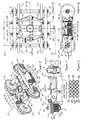
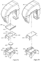
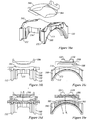
- Figure 3a shows an alternate embodiment of wheelset to sideframe interface assembly, indicated most generally as 150.
- the pedestal region of sideframe 151 as shown in Figure 3a , is substantially similar to those shown in the previous examples, and may be taken as being the same except insofar as may be noted.
- bearing 152 may be taken as representing the location of the end of a wheelset more generally, with the wheelset to sideframe interface assembly including those items, members or elements that are mounted between bearing 152 and sideframe 151.
- Bearing adapter 154 may be generally similar to bearing adapter 44 in terms of its lower structure for seating on bearing 152.
- the body of bearing adapter 154 may be a casting or a forging, or a machined part, and may be made of a material that may be a relatively low cost material, such as cast iron or steel, and may be made in generally the same manner as bearing adapters have been made heretofore.
- Bearing adapter 154 may have a bi-directional rocker 153 employing a compound curvature of first and second radii of curvature according to one or another of the possible combinations of male and female radii of curvature discussed herein.
- Bearing adapter 154 may differ from those described above in that the central body portion 155 of the adapter has been trimmed to be shorter longitudinally, and the inside spacing between the corner abutment portions has been widened somewhat, to accommodate the installation of an auxiliary centering device, or centering member, or centrally biased restoring member in the nature of, for example, elastomeric bumper pads, such as those identified as resilient pads, or members 156.
- Members 156 may be considered a form of restorative centering element, and may also be termed "snubbers" or "bumper” pads.
- a pedestal seat fitting having a mating rocking surface for permitting lateral and longitudinal rocking, is identified as 158.
- fitting 158 may be made of a hard metal material, which may be a grade of steel.
- the engagement of the rocking surfaces may, again, tend to have low resistance to torsion about predominantly vertical axis through the point of contact.
- a bearing adapter 160 is substantially similar to bearing adapter 154, but differs in having a central recess, socket, cavity or accommodation, indicated generally as 161 for receiving an insert identified as a first, or lower, rocker member 162.
- the main, or central portion of the body 159 of bearing adapter 160 may be of shorter longitudinal extent than might otherwise be the case, being truncated, or relieved, to accommodate resilient members 156.
- Accommodation 161 may have a plan view form whose periphery may include one or more keying, or indexing, features or fittings, of which cusps 163 may be representative.
- Cusps 163 may receive mating keying, or indexing, features or fittings of rocker member 162, of which lobes 164 may be taken as representative examples.
- Cusps 163 and lobes 164 may fix the angular orientation of the lower, or first, rocker member 162 such that the appropriate radii of curvature may be presented in each of the lateral and longitudinal directions.
- cusps 163 may be spaced unequally about the periphery of accommodation 161 (with lobes 164 being correspondingly spaced about the periphery of the insert member 162 ) in a specific spacing arrangement to prevent installation in an incorrect orientation, (such as 90 degrees out of phase).
- one cusp may be spaced 80 degrees of arc about the periphery from one neighbouring cusp, and 100 degrees of arc from another neighbouring cusp, and so on to form a rectangular pattern.
- lobes 164 being correspondingly spaced about the periphery of the insert member 162
- body 159 of bearing adapter 160 may be made of cast iron or steel
- the insert namely first rocker member 162
- the insert, member 162 may be made of a different material. That different material may present a hardened metal rocker surface such as may have been manufactured by a different process.
- the insert, member 162 may be made of a tool steel, or of a steel such as may be used in the manufacture of ball bearings.
- upper surface 165 of insert member 162, which includes that portion that is in rocking engagement with the mating pedestal seat 168, may be machined or otherwise formed to a high degree of smoothness, akin to a ball bearing surface, and may be heat treated, to give a finished bearing part.
- pedestal seat 168 may be made of a hardened material, such as a tool steel or a steel from which bearings are made, formed to a high level of smoothness, and heat treated as may be appropriate, having a surface formed to mate with surface 165 of rocker member 162.
- pedestal seat 168 may have an accommodation indicated as 167, and an insert member, identified as upper or second rocker member 166, analogous to accommodation 161 and insert member 162, with keying or indexing such as may tend to cause the parts to seat in the correct orientation.
- Member 166 may be formed of a hard material in a manner similar to member 162, and may have a downward facing rocking surface 157, which may be machined or otherwise formed to a high degree of smoothness, akin to a ball or roller bearing surface, and may be heat treated, to give a finished bearing part surface for mating, rocking engagement with surface 165.
- rocker member 162 has both male radii, and the female radii of curvature are both infinite such that the female surface is planar
- a wear member having a planar surface such as a spring clip may be mounted in a sprung interference fit in the pedestal roof in lieu of pedestal seat 168.
- the spring clip may be a clip on "Dyna-Clip" (t.m.) pedestal roof wear plate such as supplied by TransDyne Inc. Such a clip is shown in an isometric view in Figure 8a as item 354.
- FIG. 3e shows an alternate embodiment of wheelset to sideframe interface assembly, indicated generally as 170.
- Assembly 170 may include a bearing adapter 171, a pair of resilient members 156, a rocking assembly that may include a boot, resilient ring or retainer, 172, a first rocker member 173, and a second rocker member 174.
- a pedestal seat may be provided to mount in the roof of the pedestal as described above, or second rocker member 174 may mount directly in the pedestal roof.
- Bearing adapter 171 is generally similar to bearing adapter 44, or 154, in terms of its lower structure for seating on bearing 152.
- the body of bearing adapter 171 may be a casting or a forging, or a machined part, and may be made of a material that may be a relatively low cost material, such as cast iron or steel.
- Bearing adapter 171 may be provided with a central recess, socket, cavity or accommodation, indicated generally as 176, for receiving rocker member 173 and rocker member 174, and retainer 172.
- the ends of the main portion of the body of bearing adapter 171 may be of relatively short extent to accommodate resilient members 156.
- Accommodation 176 may have the form of a circular opening, that may have a radially inwardly extending flange 177, whose upwardly facing surface 178 defines a circumferential land upon which to seat first rocker member 173.
- Flange 177 may also include drain holes 178, such as may be 4 holes formed on 90 degree centers, for example.
- Rocker member 173 has a spherical engagement surface.
- First rocker member 173 may include a thickened central portion, and a thinner radially distant peripheral portion, having a lower radial edge, or margin, or land, for seating upon, and for transferring vertical loads into, flange 177.
- First rocker member 173 may be made of a different material from the material from which the body of bearing adapter 156 is made more generally. That is to say, rocker member 173 may be made of a hard, or hardened material, such as a tool steel or a steel such as might be used in a bearing, that may be finished to a generally higher level of precision, and to a finer degree of surface roughness than the body of bearing adapter 156 more generally. Such a material may be suitable for rolling contact operation under high contact pressures.
- Second rocker member 174 may be a disc of circular shape (in plan view) or other suitable shape having an upper surface for seating in pedestal seat 168, or, in the event a pedestal seat member is not used, then formed directly to mate with the pedestal roof having an integrally formed seat.
- First rocker member 173 may have an upper, or rocker surface 175, having a profile such as may give bi-directional lateral and longitudinal rocking motion when used in conjunction with the mating second, or upper rocker member, 174.
- Second rocker member 174 may be made of a different material from the material from which the body of bearing adapter 171, or the pedestal seat, is made more generally.
- Second rocker member 174 may be made of a hard, or hardened material, such as a tool steel or a steel such as might be used in a bearing, that may be finished to a generally higher level of precision, and to a finer degree of surface roughness than the body of sideframe 151 more generally.
- a material may be suitable for rolling contact operation under high contact pressures, particularly as when operated in conjunction with first rocker member 173.
- that material may tend to be rather more costly than the cast iron or relatively mild steel from which bearing adapters may otherwise tend to be made.
- an insert of this nature may be removed and replaced when worn, either on the basis of a scheduled rotation, or as the need may arise.
- Resilient member 172 may be made of a composite or polymeric material, such as a polyurethane. Resilient member 172 may also have apertures, or reliefs 179 such as may be placed in a position for co-operation with corresponding drain holes 178.
- the wall height of resilient member 172 may be sufficiently tall to engage the periphery of first rocker member 173. Further, a portion of the radially outwardly facing peripheral edge of the second, upper, rocking member 174, may also lie within, or may be partially overlapped by, and may possibly slightly stretchingly engage, the upper margin of resilient member 172 in a close, or interference, fit manner, such that a seal may tend to be formed to exclude dirt or moisture. In this way the assembly may tend to form a closed unit. In that regard, such space as may be formed between the first and second rockers 173, 174 inside the dirt exclusion member may be packed with a lubricant, such as a lithium or other suitable grease.
- resilient members 156 may have the general shape of a channel, having a central, or back, or transverse, or web portion 181, and a pair of left and right hand, flanking wing portions 182, 183.
- Wing portions 182 and 183 may tend to have downwardly and outwardly tending extremities that may tend to have an arcuate lower edge such as may seat over the bearing casing.
- the inside width of wing portions 182 and 183 may be such as to seat snugly about the sides of thrust blocks 180.
- a transversely extending lobate portion 185, running along the upper margin of web portion 181, may seat in a radiused rebate 184 between the upper margin of thrust blocks 180 and the end of pedestal seat 168.
- the inner lateral edge 186 of lobate portion 185 may tend to be chamfered, or relieved, to accommodate, and to seat next to, the end of pedestal seat 168.
- the rocking assembly at the wheelset to sideframe interface may tend to maintain itself in a centered condition.
- the torsionally de-coupled bi-directional rocker arrangements disclosed herein may tend to have rocking stiffnesses that are proportional to the weight placed upon the rocker.
- a longitudinal rocking surface is used to permit self-steering, and the truck is experiencing reduced wheel load, (such as may approach wheel lift), or where the car is operating in the light car condition
- an auxiliary restorative centering element may include a biasing element tending to urge the bearing adapter to a longitudinally centered position relative to the pedestal roof, and whose restorative tendency may be independent of the gravitational force experienced at the wheel. That is, when the bearing adapter is under less than full load, or is unloaded, it may be desirable to maintain a bias to a central position.
- Resilient members 156 described above may operate to urge such centering.
- Figures 3c and 3d illustrate the spatial relationship of the sandwich formed by (a) the bearing adapter, for example, bearing adapter 154; (b) the centering member, such as, for example, resilient members 156; and (c) the pedestal jaw thrust blocks, 180.
- Ancillary details such as, for example, drain holes or phantom lines to show hidden features have been omitted from Figures 3c and 3d for clarity.
- bearing adapter 154 (or 171, as may be); may tend to be centered relative to jaws 180.
- the snubber member 156
- the snubber may seat closely about the pedestal jaw thrust lug, and may seat next to the bearing adapter end wall and between the bearing adapter corner abutments in a slight interference fit.
- the snubber may be sandwiched between, and may establish the spaced relative position of, the thrust lug and the bearing adapter and may provide an initial central positioning of the mating rocker elements as well as providing a restorative bias.
- bearing adapter 154 may still rock relative to the sideframe, such rocking may tend to deform (typically, locally to compress) a portion of member 156, and, being elastic, member 156 may tend to urge bearing adapter 154 toward a central position, whether there is much weight on the rocking elements or not.
- Resilient member 156 may have a restorative force-deflection characteristic in the longitudinal direction that is substantially less stiff than the force deflection characteristic of the fully loaded longitudinal rocker (perhaps one to two orders of magnitude less), such that, in a fully loaded car condition, member 156 may tend not significantly to alter the rocking behaviour.
- member 156 may be made of a polyurethane having a Young's modulus of some 6,500 p.s.i. In another embodiment the Young's modulus may be about 13,000 p.s.i. The Young's modulus of the elastomeric material may be in the range of 4 to 20 k.p.s.i. The placement of resilient members 156 may tend to center the rocking elements during installation.
- the force to deflect one of the snubbers may be less than 20 % of the force to deflect the rocker a corresponding amount under the light car (i.e., unloaded) condition, and may, for small deflections, have an equivalent force/deflection curve slope that may be less than 10 % of the force deflection characteristic of the longitudinal rocker.
- Figure 5 shows an isometric view of an end portion of a truck bolster 210.
- bolster 210 is symmetrical about the central longitudinal vertical plane of the bolster (i.e., cross-wise relative to the truck generally) and symmetrical about the vertical mid-span section of the bolster (i.e., the longitudinal plane of symmetry of the truck generally, coinciding with the railcar longitudinal center line).
- Bolster 210 has a pair of spaced apart bolster pockets 212, 214 for receiving damper wedges 216, 218. Pocket 212 is laterally inboard of pocket 214 relative to the side frame of the truck more generally. Wear plate inserts 220, 222 are mounted in pockets 212, 214 along the angled wedge face.
- wedges 216, 218 have a primary angle, ⁇ as measured between vertical and the angled trailing vertex 228 of outboard face 230.
- primary angle ⁇ may tend to lie in the range of 35 - 55 degrees, possibly about 40 - 50 degrees.
- This same angle ⁇ is matched by the facing surface of the bolster pocket, be it 212 or 214.
- a secondary angle ⁇ gives the inboard, (or outboard), rake of the sloped surface 224, (or 226 ) of wedge 216 (or 218 ).
- the true rake angle can be seen by sighting along plane of the sloped face and measuring the angle between the sloped face and the planar outboard face 230.
- the rake angle is the complement of the angle so measured.
- the rake angle may tend to be greater than 5 degrees, may lie in the range of 5 to 20 degrees, and is preferably about 10 to 15 degrees. A modest rake angle may be desirable.
- the damper wedges may tend to work in their pockets.
- the rake angles yield a component of force tending to bias the outboard face 230 of outboard wedge 218 outboard against the opposing outboard face of bolster pocket 214.
- the inboard face of wedge 216 may tend to be biased toward the inboard planar face of inboard bolster pocket 212.
- These inboard and outboard faces of the bolster pockets may be lined with a low friction surface pad, indicated generally as 232.
- the left hand and right hand biases of the wedges may tend to keep them apart to yield the full moment arm distance intended, and, by keeping them against the planar facing walls, may tend to discourage twisting of the dampers in the respective pockets.
- Bolster 210 includes a middle land 234 between pockets 212, 214, against which another spring 236 may work.
- Middle land 234 is such as might be found in a spring group that is three (or more) coils wide. However, whether two, three, or more coils wide, and whether employing a central land or no central land, bolster pockets can have both primary and secondary angles as illustrated in the example embodiment of Figure 5a , with or without wear inserts.
- the opposing side frame column wear plates need not be monolithic. That is, two wear plate regions could be provided, one opposite each of the inboard and outboard dampers, presenting planar surfaces against which the dampers can bear. The normal vectors of those regions may be parallel, the surfaces may be co-planar and perpendicular to the long axis of the side frame, and may present a clear, un-interrupted surface to the friction faces of the dampers.
- Figure 1e shows an example of a three piece railroad car truck, shown generally as 250.
- Truck 250 has a truck bolster 252, and a pair of sideframes 254.
- the spring groups of truck 250 are indicated as 256.
- Spring groups 256 are spring groups having three springs 258 (inboard corner), 260 (center) and 262 (outboard corner) most closely adj acent to the sideframe columns 254.
- a motion calming, kinematic energy dissipating element, in the nature of a friction damper 264, 266 is mounted over each of central springs 260.
- Friction damper 264, 266 has a substantially planar friction face 268 mounted in facing, planar opposition to, and for engagement with, a side frame wear member in the nature of a wear plate 270 mounted to sideframe column 254.
- the base of damper 264, 266 defines a spring seat, or socket 272 into which the upper end of central spring 260 seats.
- Damper 264,266 has a third face, being an inclined slope or hypotenuse face 274 for mating engagement with a sloped face 276 inside sloped bolster pocket 278. Compression of spring 260 under an end of the truck bolster may tend to load damper 264 or 266, as may be, such that friction face 268 is biased against the opposing bearing face of the sideframe column, 280.
- Truck 250 also has wheelsets whose bearings are mounted in the pedestal 284 at either ends of the side frames 254. Each of these pedestals may accommodate one or another of the sideframe to bearing adapter interface assemblies described above and may thereby have a measure of self steering.
- vertcal face 268 of friction damper 264, 266 may have a bearing surface having a co-efficient of static friction, : s , and a co-efficient of dynamic or kinetic friction, : k , that may tend to exhibit little or no "stick-slip" behaviour when operating against the wear surface of wear plate 270.
- the coefficients of friction are within 10 % of each other.
- the coefficients of friction are substantially equal and may be substantially free of stick-slip behaviour.
- the coefficients of friction when dry, may be in the range of 0.10 to 0.45, may be in the narrower range of 0.15 to 0.35, and may be about 0.30.
- Friction damper 264, 266 may have a friction face coating, or bonded pad 286 having these friction properties, and corresponding to those inserts or pads described in the context of Figures 6a- 6c , and Figures 7a - 7h .
- Bonded pad 286 may be a polymeric pad or coating.
- a low friction, or controlled friction pad or coating 288 may also be employed on the sloped surface of the damper.
- coating or pad 288 may have coefficients of static and dynamic friction that are within 20 %, or, more narrowly, 10 % of each other.
- the coefficients of static and dynamic friction are substantially equal.
- the co-efficient of dynamic friction may be in the range of 0.10 to 0.30, and may be about 0.20.
- the bodies of the damper wedges themselves may be made from a relatively common material, such as a mild steel or cast iron.
- the wedges may then be given wear face members in the nature of shoes, wear inserts or other wear members, which may be intended to be consumable items.
- a damper wedge is shown generically as 300.
- the replaceable, friction modification consumable wear members are indicated as 302, 304.
- the wedges and wear members may have mating male and female mechanical interlink features, such as the cross-shaped relief 303 formed in the primary angled and vertical faces of wedge 300 for mating with the corresponding raised cross shaped features 305 of wear members 302, 304.
- Sliding wear member 302 may be made of a material having specified friction properties, and may be obtained from a supplier of such materials as, for example, brake and clutch linings and the like, such as Railway Friction Products.
- the materials may include materials that are referred to as being non-metallic, low friction materials, and may include UHMW polymers.
- Figures 6a and 6c show consumable inserts in the nature of wear plates, namely wear members 302, 304
- the entire bolster pocket may be made as a replaceable part. It may be a high precision casting, or may include a sintered powder metal assembly having suitable physical properties. The part so formed may then be welded into place in the end of the bolster.
- wedge 300 may have a seat, or socket 307, for engaging the top end of the spring coil, whichever spring it may be, spring 262 being shown as typically representative.
- Socket 307 serves to discourage the top end of the spring from wandering away from the intended generally central position under the wedge.
- a bottom seat, or boss, for discouraging lateral wandering of the bottom end of the spring is shown in Figure 1e as item 308. It may be noted that wedge 300 has a primary angle, but does not have a secondary rake angle.
- wedge 300 may be used as damper 264, 266 of truck 250 of Figure 1e , for example, and may provide friction damping with little or no "stick-slip" behaviour, but rather friction damping for which the coefficients of static and dynamic friction are equal, or only differ by a small (less than about 20%, perhaps less than 10%) difference.
- Wedge 300 may be used in truck 250 in conjunction with a bi-directional bearing adapter of any of the embodiments described herein. Wedge 300 may also be used in a four cornered damper arrangement, as in truck 22, for example, where wedges may be employed that may lack secondary angles.
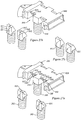
- a damper 310 is shown such as may be used in truck 22, or any of the other double damper trucks described herein, such as may have appropriately formed, mating bolster pockets. Damper 310 is similar to damper 300, but may include both primary and secondary angles. Damper 310 may, arbitrarily, be termed a right handed damper wedge. Figures 7a - 7e are intended to be generic such that it may be understood also to represent the left handed, mirror image of a mating damper with which damper 310 would form a matched pair.
- Wedge 310 has a body 312 that may be made by casting or by another suitable process.
- Body 312 may be made of steel or cast iron, and may be substantially hollow.
- Body 312 has a first, substantially planar platen portion 314 having a first face for placement in a generally vertical orientation in opposition to a sideframe bearing surface, for example, a wear plate mounted on a sideframe column.
- Platen portion 314 may have a rebate, or relief, or depression formed therein to receive a bearing surface wear member, indicated as member 316.
- Member 316 may be a material having specific friction properties when used in conjunction with the sideframe column wear plate material.
- member 316 may be formed of a brake lining material, and the column wear plate may be formed from a high hardness steel.
- Body 312 may include a base portion 318 that may extend rearwardly from and generally perpendicularly to, platen portion 314.
- Base portion 318 may have a relief 320 formed therein in a manner to form, roughly, the negative impression of an end of a spring coil, such as may receive a top end of a coil of a spring of a spring group, such as spring 262.
- Base portion 318 may join platen portion 314 at an intermediate height, such that a lower portion 321 of platen portion 314 may depend downwardly therebeyond in the manner of a skirt. That skirt portion may include a corner, or wrap around portion 322 formed to seat around a portion of the spring.
- Body 312 may also include a diagonal member in the nature of a sloped member 324.
- Sloped member 324 may have a first, or lower end extending from the distal end of base 318 and running upwardly and forwardly toward a junction with platen portion 314.
- An upper region 326 of platen portion 314 may extend upwardly beyond that point of junction, such that damper wedge 310 may have a footprint having a vertical extent somewhat greater than the vertical extent of sloped member 324.
- Sloped member 324 may also have a socket or seat in the nature of a relief or rebate 328 formed therein for receiving a sliding face member 330 for engagement with the bolster pocket wear plate of the bolster pocket into which wedge 310 may seat.
- sloped member 324 (and face member 330 ) are inclined at a primary angle ⁇ , and a secondary angle ⁇ .
- Sliding face member 330 may be an element of chosen, possibly relatively low, friction properties (when engaged with the bolster pocket wear plate), such as may include desired values of coefficients of static and dynamic friction.
- the coefficients of static and dynamic friction may be substantially equal, may be about 0.2 (+/- 20 %, or, more narrowly +/- 10%), and may be substantially free of stick-slip behaviour.
- a damper wedge 332 is similar to damper wedge 310, but, in addition to pads or inserts for providing modified or controlled friction properties on the friction face for engaging the sideframe column and on the face for engaging the slope of the bolster pocket, damper wedge 332 may have pads or inserts such as pad 334 on the side faces of the wedge for engaging the side faces of the bolster pockets. In this regard, it may be desirable for pad 334 to have low coefficients of friction, and to tend to be free of stick slip behaviour.
- the friction materials may be cast or bonded in place, and may include mechanical interlocking features, such as shown in Figure 6a , or bosses, grooves, splines, or the like such as may be used for the same purpose.
- a damper wedge 336 is provided in which the slope face insert or pad, and the side wall insert or pad form a continuous, or monolithic, element, indicated as 338.
- the material of the pad or insert may, again, be cast in place, and may include mechanical interlock features.
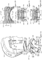
- Figures 8a - 8f show an alternate bearing adapter assembly to that of Figure 3a .
- the assembly indicated generally as 350, may differ from that of Figure 3a insofar as bearing adapter 344 may have an upper surface 346 that may be a load bearing interface surface of significant extent, that may be substantially planar and horizontal, such that it may act as a base upon which to seat a rocker element, 348.
- Rocker element 348 may have an upper, or rocker, surface 352 having a suitable profile, such as a compound curvatures having lateral and longitudinal radii of curvature, for mating with a corresponding rocker engagement surface of a pedestal seat liner 354.
- each of the two rocking engagement surface may have both lateral and longitudinal radii of curvature, such that there are mating lateral male and female radii, and mating longitudinal male and female radii.
- both the female radii may be infinite, such that the pedestal seat may have a planar engagement surface, and the pedestal seat liner may be a wear liner, or similar device.
- Rocker element 348 may also have a lower surface 356 for seating on, mating with, and for transferring loads into, upper surface 346 over a relatively large surface area, and may have a suitable through thickness for diffusing vertical loading from the zone of rolling contact to the larger area of the land (i.e., surface 346, or a portion thereof) upon which rocker element 348 sits.
- Lower surface 356 may also include a keying, or indexing feature 358 of suitable shape, and may include a centering feature 360, both to aid in installation, and to aid in re-centering rocker element 348 in the event that it should be tempted to migrate away from the central position during operation.
- Indexing feature 358 may also include an orienting element for discouraging misorientation of rocker element 348.
- Indexing feature 358 may be a cavity 362 of suitable shape to mate with an opposed button 364 formed on the upper surface 346 of bearing adapter 344. If this shape is non-circular, it may tend to admit of only one permissible orientation.
- the orienting element may be defined in the plan form shape of cavity 362 and button 364. Where the various radii of curvature of rocker element 348 differ in the lateral and longitudinal directions, it may be that two positions 180 degrees out of phase may be acceptable, whereas another orientation may not.
- cavity 362 and button 364 may be chosen from a large number of possibilities, and may have a cruciform or triangular shape, or may include more than one raised feature in an asymmetrical pattern, for example.
- the centering feature may be defined in the tapered, or sloped, flanks 368 and 370 of cavity 362 and 364 respectively, in that, once positioned such that flanks 368 and 370 begin to work against each other, a normal force acting downward on the interface may tend to cause the parts to center themselves.
- Rocker element 348 has an external periphery 372, defining a footprint.
- Resilient members 374 may be taken as being the same as resilient members 156, noted above, except insofar as resilient members 374 may have a depending end portion for nesting about the thrust block of a jaw of the pedestal, and also a predominantly horizontally extending portion 376 for overlying a substantial portion of the generally flat or horizontal upper region of bearing adapter 344.
- the outlying regions of surface 346 of bearing adapter 344 may tend to be generally flat, and may tend, due to the general thickness of rocker element 348, to be compelled to stand in a spaced apart relationship from the opposed, downwardly facing surface of the pedestal seat, such as may be, for example, the exposed surface of a wear liner such as item 354, or a seat such as item 168, or such other mating part as may be suitable.
- Portion 376 is of a thickness suitable for lying in the gaps so defined, and may tend to be thinner than the mean gap height so as not to interfere with operation of the rocker elements.
- Horizontally extending portion 376 may have the form of a skirt such as may include a pair of left and right hand arms or wings 378 and 380 having a profile, when seen in plan view, for embracing a portion of periphery 372.
- Resilient member 374 has a relief 382 defined in the inwardly facing edge. Where rocker member 348 has outwardly extending blisters, or cusps, akin to item 164, relief 382 may function as an indexing or orientation feature. A relatively coarse engagement of rocker element 348 may tend to result in wings 378 and 380 urging rocker element 348 to a generally centered position relative to bearing adapter 344.
- This coarse centering may tend to cause cavity 362 to pick up on button 364, such that rocker member 348 is then urged to the desired centered position by a fine centering feature, namely the chamfered flanks 368, 370.
- the root of portion 376 may be relieved by a radius 384 adjacent the juncture of surface 346 with the end wall 386 of bearing adapter 348 to discourage chaffing of resilient member 372, 374 at that location.
- rocker element 348 could, alternatively, be inverted so as to, seat in an accommodation formed in the pedestal roof, with a land facing toward the roof, and a rocking surface facing toward a mating bearing adapter, be it adapter 44 or some other.
- FIG 9a shows an alternative arrangement to that of Figure 3a or Figure 8a .
- bearing adapter 404 may be substantially similar to bearing adapter 344, and may have an upper surface 406 and a rocker element 408 that interact in the same manner as rocker element 348 interacts with surface 346. (Or, in the inverted case, the rocker element may be seated in the pedestal roof, and the bearing adapter may have a mating upwardly facing rocker surface).
- the rocker element may interact with a pedestal seat fitting 410 such as may be a wear liner seated in the pedestal roof.
- Rocker element 408 and the body of bearing adapter 404 may have mating indexing features as described in the context of Figures 8a to 8e .
- assembly 400 employs a single resilient member 412, such as may be a monolithic cast material, be it polyurethane or a suitable rubber or rubberlike material such as may be used, for example, in making an LC pad or a Pennsy pad.
- An LC pad is an elastomeric bearing adapter pad available from Lord Corporation of Erie Pennsylvania.
- An example of an LC pad may be identified as Standard Car Truck Part Number SCT 5578.
- resilient member 412 has first and second end portions 414, 416 for interposition between the thrust lugs of the jaws of the pedestal and the ends 418 and 420 of the bearing adapter.
- End portions 414, 416 may tend to be a bit undersize so that, once the roof liner is in place, they may slide vertically into place on the thrust lugs, possibly in a modest interference fit.
- the bearing adapter may slide into place thereafter, and again, may do so in a slight interference fit, carrying the rocker element 408 with it into place.
- Resilient member 412 may also have a central or medial portion 422 extending between end portions 414, 416. Medial portion 422 may extend generally horizontally inward to overlie substantial portions of the upper surface bearing adapter 404.
- Resilient member 412 may have an accommodation 424 formed therein, be it in the nature of an aperture, or through hole, having a periphery of suitable extent to admit rocker element 408, and so to permit rocker element 408 to extend at least partially through member 412 to engage the mating rocking element of the pedestal seat.
- resilient member 412 may be formed in the manner of a Pennsy Pad with a suitable central aperture formed therein.
- Figure 9b shows a Pennsy pad installation.
- a bearing adapter is indicated as 430
- an elastomeric member such as may be a Pennsy pad
- member 432 seats between the pedestal roof and the bearing adapter.
- One example of such a pad is illustrated in US Patent 5,562,045 of Rudibaugh et al., issued October 6, 1996 (and which is incorporated herein by reference).
- Figure 9b may include a pad 432 and bearing adapter of 430 the same, or similar, nature to those shown and described in the 5,562,045 patent.
- the Pennsy pad may tend to permit a measure of passive steering.
- the Pennsy pad installation of Figure 9b can be installed in the sideframe of Figure 1a , in combination with a four cornered damper arrangement, as indicated in Figures 1a - 1d .
- the truck may be a Barber S2HD truck, modified to carry a damper arrangement, such as a four-cornered damper arrangement, such as may have an enhanced restorative tendency in the face of non-square deformation of the truck, having dampers that may include friction surfaces as described herein.
- FIG 10a shows a further alternate embodiment of wheelset to sideframe interface assembly to that of Figure 3a or Figure 8a .
- bearing adapter 444 may have an upper rocker surface of any of the configurations discussed above, or may have a rocker element in the manner of bearing adapter 344.
- the underside of bearing adapter 444 may have not only a circumferentially extending medial groove, channel or rebate 446, having an apex lying on the transverse plane of symmetry of bearing adapter 444, but also a laterally extending underside rebate 448 such as may tend to lie parallel to the underlying longitudinal axis of the wheelset shaft and bearing centreline (i.e., the axial direction) such that the underside of bearing adapter 444 has four corner lands or pads 450 arranged in an array for seating on the casing of the bearing.
- each of the pads, or lands may be formed on a curved surface having a radius conforming to a body of revolution such as the outer shell of the bearing.
- Rebate 448 may tend to lie along the apex of the arch of the underside of bearing adapter 444, with the intersection of rebates 446 and 448. Rebate 448 may be relatively shallow, and may be gently radiused into the surrounding bearing adapter body.
- the body of bearing adapter 444 is more or less symmetrical about both its longitudinal central vertical plane (i.e., on installation, that plane lying vertical and parallel to, if not coincident with, the longitudinal vertical central plane of the sideframe), and also about its transverse central plane (i.e., on installation, that plane extending vertically radially from the center line of the axis of rotation of the bearing and of the wheelset shaft).
- axial rebate 448 may tend to lie at the section of minimum cross-sectional area of bearing adapter 444.
- rebates 446 and 448 may tend to divide, and spread, the vertical load carried through the rocker element over a larger area of the casing of the bearing, and hence to more evenly distribute the load into the elements of the bearing than might otherwise be the case. It is thought that this may tend to encourage longer bearing life.
- bearing adapter 444 may have an upper surface having a crown to permit self-steering, or may be formed to accommodate a self-steering apparatus such as an elastomeric pad, such as a Pennsy Pad or other pad.
- a self-steering apparatus such as an elastomeric pad, such as a Pennsy Pad or other pad.
- a rocker surface is employed, whether by way of a separable insert, or a disc, or is integrally formed in the body of the bearing adapter, the location of the contact of the rocker in the resting position may tend to lie directly above the center of the bearing adapter, and hence above the intersection of the axial and circumferential rebates in the underside of bearing adapter 444.
- FIGS 11a - 11f show views of a bearing adapter 452, a pedestal seat insert 454 and elastomeric bumper pad members 456, as an assembly for insertion between bearing 46 and sideframe 26.
- Bearing adapter 452 and pad members 456 are generally similar to bearing adapter 171 and members 156, respectively. They differ, however, insofar as bearing adapter 452 has thrust block standoff elements 460, 462 located at either end thereof, and the lower corners of bumpers 456 have been truncated accordingly. It may be that for a certain range of deflection, an elastomeric response is desired, and may be sufficient to accommodate a high percentage of in-service performance.
- Standoff elements 460, 462 may act as limiting stops to bound that range of motion.
- Standoff elements 460, 462 may have the form of shelves, or abutments, or stops 466, 468 mounted to, and standing proud of, the laterally inwardly facing faces of the corner abutment portions 470, 472 of bearing adapter 452 more generally.
- stops 466, 468 underlie toes 474, 476 of members 456.
- toes 474, 476 have a truncated appearance as compared to the toes of member 356 in order to stand clear of stops 466, 468 on installation.
- stops 466, 468 may tend to stand clear of the pedestal jaw thrust blocks by some gap distance.
- the thrust lug may tend to bottom against stop 466 or 468, as the case may be.
- the sheltering width of stops 466, 468 i.e., the distance by which they stand proud of the inner face of corner abutment portions 470, 472 ) may tend to provide a reserve compression zone for wings 475, 477 and may thereby tend to prevent them from being unduly squeezed or pinched.
- Pedestal seat insert 454 may be generally similar to liner 354, but may include radiused bulges 480, 482, and a thicker central portion 484.
- Bearing adapter 452 may include a central bi-directional rocker portion 486 for mating rocking engagement with the downwardly facing rocking surface of central portion 484. The mating surfaces may conform to any of the combinations of bi-directional rocking radii discussed herein.
- Rocker portion 486 may be trimmed laterally as at longitudinally running side shoulders 488, 490 to accommodate bulges 480, 482.
- Bearing adapter 452 may also have different underside grooving, 492 in the nature of a pair of laterally extending tapered lobate depressions, cavities, or reliefs 494, 496 separated by a central bridge region 498 having a deeper section and flanks that taper into reliefs 494, 496.
- Reliefs 494, 496 may have a major axis that runs laterally with respect to the bearing adapter itself, but, as installed, runs axially with respect to the axis of rotation of the underlying bearing.
- reliefs 494, 496 may tend to leave a generally H-shaped footprint on the circumferential surface 500 that seats upon the outside of bearing 46, in which the two side regions, or legs, of the H form lands or pads 502, 504 joined by a relatively narrow waist, namely bridge region 498.
- reliefs 494, 496 may tend to run, or extend, predominantly along the apex of the profile, between the pads, or lands, that lie to either side. This configuration may tend to spread the rocker rolling contact point load into pads 502, 504 and thence into bearing 46.
- Bearing life may be a function of peak load in the rollers.
- Reliefs 494, 496 may tend to prevent the vertical load being passed in a concentrated manner predominantly into the top rollers in the bearing. Instead, it may be advantageous to spread the load between several rollers in each race. This may tend to be encouraged by employing spaced apart pads or lands, such as pads 502, 504, that seat upon the bearing casing.
- Central bridge region 498 may seat above a section of the bearing casing under which there is no race, rather than directly over one of the races. Bridge region 498 may act as a central circumferential ligature, or tension member, intermediate bearing adapter end arches 506, 508 such as may tend to discourage splaying or separation of pads 502, 504 away from each other as vertical load is applied.
- Figures 12a to 12d show an alternate assembly to that of Figure 11a , indicated generally as 510 for seating in a sideframe 512.
- Bearing 46 and bearing adapter 452 may be as before.
- Assembly 510 may include an upper rocker fitting identified as pedestal seat member 514, and resilient members 516.
- Sideframe 512 may be such that the upper rocker fitting, namely pedestal seat member 514 may have a greater through thickness, t s , than otherwise.
- This thickness, t s may be greater than 10 % of the magnitude of the width W s of the pedestal seat member, and may be about 20 (+/-5) % of the width. In one embodiment the thickness may be roughly the same as the thickness of and 'LC pad' such as may be obtained from Lord Corporation.
- Pedestal seat member 514 may tend to have a greater thickness for enhancing the spreading of the rocker contact load into sideframe 512. It may also be used as part of a retro-fit installation in sideframes such as may formerly have been made to accommodate LC pads.
- Pedestal seat member 514 may have a generally planar body 518 having upturned lateral margins 520 for bracketing, and seating about, the lower edges of the sideframe pedestal roof member 522. The major portion of the upper surface of body 518 may tend to mate in planar contact with the downwardly facing surface of roof member 522.
- Seat member 514 may have protruding end potions 524 that extend longitudinally from the main, planar portion of body 518. End portions 524 may include a deeper nose section 526, that may stand downwardly proud of two wings 528, 530. The depth of nose section 526 may correspond to the general through thickness depth of member 514.
- the lower, downwardly facing surface 532 of member 518 may be formed to mate with the upper surface of the bearing adapter, such that a bi-directional rocking interface is achieved, with a combination of male and female rocking radii as described herein.
- the female rocking surface may be planar.
- Resilient members 516 may be formed to engage protruding portions 524. That is, resilient member 516 may have the generally channel shaped for of resilient member 156, having a lateral web 534 standing between a pair of wings 536, 538. However, in this embodiment, web 534 may extend, when installed, to a level below the level of stops 466, 468, and the respective base faces 540, 542 of wings 536, 538 are positioned to sit above stops 466, 468. A superior lateral wall, or bulge, 544 surmounts the upper margin of web 534, and extends longitudinally, such as may permit it to overhang the top of the sideframe jaw thrust lug 546.
- the upper surface of bulge 544 may be trimmed, or flattened to accommodate nose section 526.
- the upper extremities of wings 536, 538 terminate in knobs, or prongs, or horns 548, 550 that stand upwardly proud of the flattened surface 552 of bulge 544. As installed, the upper ends of horns 548, 550 underlie the downwardly facing surfaces of wings 536, 538.
- the height of horns 548, 550 is sufficient to prevent the rocker surface of bearing adapter 452 from engaging sideframe roof member 522. That is, the height of the highest portion of the crown of the rocker surface 552 of the bearing adapter is less than the height of the ends of horns 548, 550 when horns 548, 550 are in contact with stops 466, 468.
- nose section 526 is located between wings 536, 538, and wings 536, 538 are captured above horns 548, 550. In this way, resilient members 514, and in particular horns 548, 550, act as installation error detection elements, or damage prevention elements.
- the steps of installation may include the step of removing an existing bearing adapter, removing an existing elastomeric pad, such as an LC pad, installing pedestal seat fitting 514 in engagement with roof 522; seating of resilient members 514 above each of thrust lugs 546; and sliding bearing adapter 452 between resilient pad members 514.
- Resilient pad members 514 then serve to locate other elements on assembly, to retain those elements in service, and to provide a centering bias to the mating rocker elements, as discussed above.
- Figures 13a to 13g show and alternate bearing adapter 144 and pedestal seat 146 pair.
- Bearing adapter 144 is substantially the same as bearing adapter 44, except insofar as bearing adapter 44 has a fully curved top surface 142, whereas bearing adapter 144 has an upper surface that has a flat central portion 148 between somewhat elevated side portions 149.
- the male bearing surface portion 147 is located centrally on flat central portion 148, and extends upwardly therefrom.
- bearing adapter 144 has first and second radii r 1 and r 2 , formed in the longitudinal and transverse directions respectively, such that the upwardly protruding surface so formed is a toroidal surface.
- Pedestal seat 146 is substantially similar to pedestal seat fitting 38.
- Pedestal seat 146 has a body having an upper surface 145 that seats in planar abutment against the downwardly facing surface of pedestal roof 120, and upwardly extending tangs 124 that engage lugs 122 as before. While in the general sense, the female engagement fitting portion, namely the hollow depression formed in the lower face of seat 146, is formed on longitudinal and lateral radii R 1 and R 2 , as above, when these two radii are equal a spherical surface 143 is formed, giving the circular plan view of Figure 13a .
- Figures 13f and 13g serve to illustrate that the male and female surfaces may be inverted, such that the female engagement surface 560 is formed on bearing adapter 562, and the male engagement surface 564 on seat 566.
- Figures 14a - 14e show enlarged views of bearing adapter 44 and pedestal seat fitting 38.
- the compound curve of upwardly facing surface 142 runs fully to terminate at the end faces 134, and the side faces 570 of bearing adapter 44.
- the side faces show the circularly downwardly arched lower walls margins 572 of side faces 570 that seat about bearings 46.
- bearing adapter 44 can be taken as being the same as bearing adapter 144.
- Figures 15a - 15c show a conceptually similar bearing adapter and pedestal seat combination to that of Figures 13a to 13g , but rather than having the interface portions standing proud of the remainder of the bearing adapter, the male portion 574 is sunken into the top of the bearing adapter, and the surrounding surface 576 is raised up.
- the mating female portion 578 while retaining its hollowed out shape, stands proud of the surrounding structure of the seat to provide a corresponding mating surface.
- the longitudinally extending phantom lines indicate drain ports to discourage the collection of water.
- a bearing adapter 580 is of substantially the same construction as bearing adapters 44 and 144, except insofar as bearing adapter 580 has an upper surface 592 that has a male fitting in the nature of a longitudinally extending crown 582 with a laterally extending axis of rotation, for which the radius of curvature is r 1 , and a female fitting in the nature of a longitudinally extending trough 584 having a lateral radius of curvature R 2 .
- pedestal fitting 586 mounted in roof 120 has a generally downwardly facing surface 594 that has a transversely extending trough 588 having a longitudinally oriented radius of curvature R 1 , for engagement with r 1 of crown 582, and a longitudinally running, downwardly protruding crown 590 having a transverse radius of curvature r 2 for engagement with R 2 of trough 584.
- the saddle surfaces are inverted such that whereas bearing adapter 580 has r 1 and R 2 , bearing adapter 596 has r 2 and R 1 .
- pedestal fitting 586 has r 2 and R 1
- pedestal fitting 598 has r 1 and R 2 .
- the smallest of R 1 and R 2 may be larger than, or equal to, the largest of r 1 and r 2 , and the mating opposed saddle surfaces, over the desired range of motion, may tend to be torsionally decoupled as in bearing adapters 44 and 144.
- a pedestal seat to bearing adapter interface assembly having line contact rocker interfaces is represented by Figures 17a to 17d .
- a bearing adapter 600 has a hollowed out transverse cylindrical upper surface 602, acting as a female engagement fitting portion formed on radius R 1 .
- Surface 602 may be a round cylindrical section, or it may be parabolic, or other cylindrical section.
- the corresponding pedestal seat fitting 604 may have a longitudinally extending female fitting, or trough, 606 having a cylindrical surface 608 formed on radius r 1 .
- fitting 604 is cylindrical, and may be a round cylindrical section although, alternatively, it could be parabolic, elliptic, or some other shape for producing a rocking motion.
- Trapped between bearing adapter 600 and pedestal seat fitting 604 is a rocker member 610.
- Rocker member 610 has a first, or lower portion 612 having a protruding male cylindrical rocker surface 614 formed on a radius r 1 for line contact engagement of surface 602 of bearing adapter 600 formed on radius R 1 , r 1 being smaller than R 1 , and thus permitting longitudinal rocking to obtain passive self steering.
- Lower portion 612 also has an upper relief 616 that may be machined to a high level of flatness.
- Lower portion 612 also has a centrally located, integrally formed upwardly extending cylindrical stub 618 that stands perpendicularly proud of surface 616.
- a bushing 620 which may be a press fit bushing, mounts on stub 618.
- Rocker member 600 also has an upper portion 622 that has a second protruding male cylindrical rocker surface 624 formed on a radius r 2 for line contact engagement with the cylindrical surface 608 of trough 606, formed on radius R 2 , thus permitting lateral rocking of sideframe 26.
- Upper portion 622 may have a lower relief 626 for placement in opposition to relief 616.
- Upper portion 622 has a centrally located blind bore 628 of a size for tight fitting engagement of bushing 620, such that a close tolerance, pivoting connection is obtained that is largely compliant to pivotal motion about the vertical, or z, axis of upper portion 622 with respect to lower portion 612.
- bearing 630 may be installed about stub 618 and bushing 620 and is placed between opposed surfaces 606 and 616 to encourage relative rotational motion therebetween.
- stub 618 could be formed in upper portion 622, and bore 618 formed in lower portion 612, or, alternatively, bores 628 could be formed in both upper portion 612 and lower portion 622, and a freely floating stub 618 and bushing 620 could be captured between them. It may be noted that the angular displacement about the z axis of upper portions 622 relative to lower portion 612 may be quite small - of the order of 1 degree, and may tend not to be even that large overly frequently.
- Bearing adapter 600 may have longitudinally extending raised lateral abutment side walls 632 to discourage lateral migration, or escape of lower portion 612.
- Lower portion 612 may have non-galling, relatively low co-efficient of friction side wear shim stock members 634 trapped between the end faces of lower portion 612 and side walls 632.
- Bearing adapter 600 may also have a drain hole formed therein, possibly centrally, or placed at an angle.
- pedestal seat fitting 604 may have laterally extending depending end abutment walls 636 to discourage longitudinal migration, or escape, of upper portion 622.
- non-galling, relatively low co-efficient of friction end wear shim stock members 638 may be mounted between the end faces of upper portion 622 and end abutment walls 636.
- the longitudinal cylindrical trough could be formed on the bearing adapter, and the lateral cylindrical trough could be formed in the pedestal seat, with corresponding changes in the entrapped rocker element.
- the male cylindrical portions be part of the entrapped rocker element. Rather, one of those male portions could be on the bearing adapter, and one of those male portions could be on the pedestal seat, with the corresponding female portions being formed on the entrapped rocker element.
- the rocker element could include one male element, and one female element, having the male element formed on r 1 (or r 2 ) being located on the bearing adapter, and the female element formed on R 1 (or R 2 ) being on the underside of the entrapped rocker element, and the male element formed on r 2 (or r 1 ) being formed on the upper surface of the entrapped rocker element, and the respective mating female element formed on radius R 2 (or R 1 ) being formed on the lower face of the pedestal seat.
- the rocker element could include one male element, and one female element, having the male element formed on r 1 (or r2 ) being located on the pedestal seat, and the female element formed on R 1 (or R 2 ) being on the upper surface of the entrapped rocker element, and the male element formed on r 2 (or r 1 ) being formed on the lower surface of the entrapped rocker element, and the respective mating female element formed on radius R 2 (or R 1 ) being formed on the upper face of the bearing adapter.
- the embodiment of Figures 17a - 17d may tend to yield line contact at the force transfer interfaces, and yet rock in both the longitudinal and lateral directions, with compliance to torsion about the vertical axis. That is, the bearing adapter to pedestal seat interface assembly may tend to permit rotation about the longitudinal axis to give lateral rocking motion of the side frame; rotation about a transverse axis to give longitudinal rocking motion; and compliance to torsion about the vertical axis. It may tend to discourage lateral translation, and may tend to retain high stiffness in the vertical direction.
- Figures 18a and 18b is substantially similar to the embodiment of Figures 17a to 17d .
- a rocker element 644 is captured between bearing adapter 600 and pedestal seat 604.
- Rocker element 644 has a torsional compliance element made of a resilient material, identified as elastomeric member 646 bonded between the opposed faces of the upper 647 and lower 645 portions of rocker element 644.
- Figures 18a and 18b show the laterally extending trough in bearing adapter 600, and the longitudinal trough in pedestal seat 604, the same permutations of Figure 7e may be made.
- the torsional element may be between the two cylindrical elements in a manner tending torsionally to decouple them, it may be that the elastomeric pad need not necessarily be installed between the two cylindrical members.
- the rocker element 644 may be solid, and an elastomeric element may be installed beneath the top surface of bearing adapter 600, or above the pedestal seat element, such that a torsionally compliant element is placed in series with the two rockers.
- the top of the bearing adapter could be pivotally mounted to the body of the bearing adapter more generally, or the pedestal seat could be pivotally mounted to the pedestal roof, such that a torsionally compliant element would be in series with the two rockers.
- the torsionally compliant element may be between the two rockers, such that they may tend to be torsionally de-coupled from each other.
- the male portion of the bearing adapter to pedestal seat interface may be on either the bearing adapter or on the pedestal seat, and the mating female portion (with the larger radius of curvature) may be on the other part, whichever it may be.
- the mating female portion may be on the other part, whichever it may be.
- Figures 19a to 19c show the combination of a bearing adapter 650 with an elastomeric bearing adapter pad 652 and a rocker 654 and pedestal seat 656 to permit lateral rocking of the sideframe.
- Bearing adapter 650 shown in three additional views in Figures 20a - 20c is substantially similar to bearing adapter 44 (or 144 ) to the extent of its geometric features for engaging a bearing, but differs therefrom in having a more or less conventional upper surface.
- Upper surface 658 may be flat, or may have a large (roughly 60") radius crown 660, such as might have been used for engaging a planar pedestal seat surface.
- Crown 660 is split into two fore-and-aft portions, with a laterally extending central flat portion between them.
- bearing adapter 650 has a pair of laterally proud, outwardly facing lateral lands, 662 and 664, and, amidst those lands, lateral lugs 666 that extend further still proud beyond lands 662 and 664.
- Bearing adapter pad 652 may be a commercially available assembly such as may be manufactured by Lord Corporation of Erie Pennsylvania, or such as may be identified as Standard Car Truck Part Number SCT 5844.
- Bearing adapter pad 652 has a bearing adapter engagement member in the nature of a lower plate 668 whose bottom surface 670 is relieved to seat over crown 660 in non-rocking engagement. Lateral and longitudinal translation of bearing adapter pad 652 is inhibited by an array of downwardly bent securement locating lugs, or fingers, or claws, in the nature of indexing members or tangs 672, two per side in pairs located to reach downwardly and bracket lugs 666 in close fitting engagement.
- the bracketing condition with respect to lugs 666 inhibits longitudinal motion between bearing adapter pad 652 and bearing adapter 650.
- the laterally inside faces of tangs 672 closely oppose the laterally outwardly facing surfaces of lands 662 and 664, tending thereby to inhibit lateral relative motion of bearing adapter pad 652 relative to bearing adapter 650.
- the vertical, lateral, and longitudinal position relative to bearing adapter 650 can be taken as fixed.
- Bearing adapter pad 652 also has an upper plate, 674, that, in the case of a retro-fit installation of rocker 654 and seat 656, may have been used as a pedestal seat engagement member.
- upper plate 674 has the general shape of a longitudinally extending channel member, with a central, or back, portion, 676 and upwardly extending left and right hand leg portions 678, 680 adjoining the lateral margins of back portion 676.
- Leg portions 678 may have a size and shape such as might have been suitable for mounting directly to the sideframe pedestal.
- bearing adapter pad 652 has a bonded resilient sandwich 680 that may include a first resilient layer, indicated as lower elastomeric layer 682 mounted directly to the upper surface of lower plate 668, an intermediate stiffener shear plate 684 bonded or molded to the upper surface of layer 682, and an upper resilient layer, indicated as upper elastomeric layer 686 bonded atop plate 684.
- the upper surface of layer 686 may be bonded or molded to the lower surface of upper plate 674.
- the resultant sandwich may tend to have comparatively high vertical stiffness, comparatively high resistance to torsion about the longitudinal (x) and lateral (y) axes, comparatively low resistance to torsion about the vertical (z) axis (given the small angular displacements in any case), and non-trivial, roughly equal resistance to shear in the x or y directions that may be in the range of 20,000 to 40,000 lbs per inch, or more narrowly, about 30,000 lbs per inch for small deflections.
- Bearing adapter pad 652 may tend to permit a measure of self steering to be obtained when the elastomeric elements are subjected to longitudinal shear forces.
- Rocker 654 (seen in additional views 21e, 21f and 21g ) has a body of substantially constant cross-section, having a lower surface 690 formed to sit in substantially flat, non-rocking engagement upon the upper surface of plate 674 of bearing adapterpad 652, and an upper surface 692 formed to define a male rocker surface.
- Upper surface 692 may have a continuously radius central portion 694 lying between adjacent tangential portions 696 lying at a constant slope angle.
- the central portion may describe 4 - 6 degrees of arc to either side of a central position, and may, in one embodiment have about 4-1 ⁇ 2 to 5 degrees. In the terminology used above, this radius is " r 2 ", the male radius of a lateral rocker for permitting lateral swinging motion of side frame 26.
- the radius of rocker 654 is less than the radius of the crown, perhaps less than half the crown radius, and possibly being less than 1/3 of the crown radius. It may be formed on a radius of between 5 and 20 inches, or, more narrowly, on a radius of between 8 and 15 inches. Surface 692 could also be formed on a parabolic profile, an elliptic or hyperbolic profile, or some other profile to yield lateral rocking.
- Pedestal seat 656 (seen in Figures 21a to 21d ) has a body having a major portion 700 that is substantially rectangular in plan view. When viewed from one end in the longitudinal direction, pedestal seat 656 has a generally channel shaped cross-section, in which major portion 700 forms the back 702 and two longitudinally running legs 704, 706 extend upwardly and laterally outwardly from the lateral margins of major portion 700. Legs 704 and 706 have an inner, or proximal portion 708 that extends upwardly and outwardly at an angle from the lateral margins of main portion 700, and an outer, or distal portion, or toe 710 that extends from the end of proximal portion 708 in a substantially vertical direction.
- the breadth between the opposed fingers of the channel section corresponds to the width of the sideframe pedestal roof 712, as shown in the cross-section of Figure 19b , with which legs 704 and 706 sit in close fitting, bracketing engagement.
- Legs 704 and 706 have longitudinally centrally located cut-outs, reliefs, rebates, or indexing features, identified as notches 714.
- Notches 714 seat in close fitting engagement about T-shaped lugs 716 ( Figure 19b ) that are welded to the sideframe on either side of the pedestal roof. This engagement establishes the lateral and longitudinal position of pedestal seat 656 with respect to sideframe 26.
- Pedestal seat 656 also has four laterally projecting corner lugs, or abutment fittings 718, whose longitudinally inwardly facing surfaces oppose the laterally extending end-face surfaces of the upturned legs 678 of upper plate 674 of bearing adapter pad 652. That is, the corner abutment fittings 718 on either lateral side of pedestal seat 656 bracket the ends of the upturned legs 678 of adapter pad 652 in close fitting engagement. This relationship fixes the longitudinal position of pedestal seat 656 relative to the upper plate of bearing adapter pad 652.
- Major portion 700 of pedestal seat 656 has a downwardly facing surface 700 that is hollowed out to form a depression defining a female rocking engagement surface 702.
- This surface is formed on a female radius (identified as R 2 in concordance with terminology used herein above) that is quite substantially larger than the radius of central portion 694 ( Figure 21f ) of rocker 654, such that rocker 654 and pedestal seat 656 meet in rolling line contact engagement and permit sideframe 26 to swing laterally in a lateral rocking relationship on rocker 654.
- the arcuate profile of female rocking engagement surface 702 may be such as to encourage lateral self centering of rocker 654, and may have a radius of curvature that varies from a central region to adjacent regions, which may be tangential planar regions.
- the radius of curvature of the pedestal seat may tend to be less than or equal to the crown radius.
- the central radius of curvature R 2 of surface 702, or the radius of curvature generally if constant, may be in the range of 6 to 60 inches, is preferably greater than 10 inches and less than 40 inches. It may be between 11/10 to 4 times as large as the rocker radius of curvature r 2 .
- the pedestal seat need not have the female rocker surface, and the rocker need not have the male rocker surface, but rather, these surfaces could be reversed, so that the male surface is on the pedestal seat, and the female surface is on the rocker.
- the resultant assembly may provide a generally increased softness in the lateral direction, while permitting a measure of self steering.
- the example of Figure 19a may be provided as an original installation, or may be provided as a retrofit installation.
- rocker 654 and pedestal seat 656 may be installed between an existing elastomeric pad and an existing pedestal seat, or may be installed in addition to a replacement elastomeric pad of lesser through-thickness, such that the overall height of the bearing adapter to pedestal seat interface may remain roughly the same as it was before the retrofit.
- Figures 19e and 19f represent alternate embodiments of combinations of elastomeric pads and rockers. While the embodiment of Figure 19a showed an elastomeric sandwich that had roughly equivalent response to shear in the lateral and longitudinal directions, this need not be the general case.
- elastomeric bearing adapter pad assemblies 720 and 731 have respective resilient elastomeric laminates sandwiches, indicated generally as 722 and 723 in which the stiffeners 726, 727 have longitudinally extending corrugations, or waves. In the longitudinal direction, the sandwich may tend to react in nearly pure shear, as before in the example of Figure 19a .
- an elastomeric bearing adapter pad assembly 721 has a base plate 734 having a lower surface for seating in non-rocking relationship on a bearing adapter, in the same manner as bearing adapter pad assembly 652 sits upon bearing adapter 650.
- the upper surface 735 of base plate 734 has a corrugated or wavy contour, the corrugations running lengthwise, as discussed above.
- An elastomeric laminate of a first resilient layer 736, an internal stiffener plate 737, and a second resilient layer 738 are located between base plate 734 and a correspondingly wavy undersurface of upper plate 740.
- upper plate 740 has an upper surface 742 having an integrally formed rocker contour corresponding to that of the upper surface of rocker 654.
- Pedestal seat 744 then mounts directly to, and in lateral rocking relationship with upper plate 740, without need for a separate rocker part.
- the combination of bearing adapter pad 721 and pedestal seat 742 may have interconnecting abutments 747 to prevent longitudinal migration of rocker surface 742 relative to the contoured downwardly facing surface 748 of pedestal seat 744.
- Figures 22a to 22c show a bearing 750 mounted on one of the end of an axle 752.
- Bearing 750 has an integrally formed arcuate rolling contact surface 754 for mating rolling point contact with a mating rolling contact surface 756 of a pedestal seat fitting 758.
- the general geometry of the rolling relationship is as described above in terms of the possible relationships of r 1 , R 1 and L , and, as noted above, the male and female rolling contact surfaces can be reversed, such that the male surface is on the pedestal seat, and the female surface is on the bearing, or further still, in the case of a compound curvature, the surfaces made be saddle shaped, as described above.
- the bearing illustrations of Figures 22b and 23b are based on the bearing cross-section illustration shown on page 812 of the 1997 Car and Locomotive Cyclopedia . That illustration was provided to the Cyclopedia courtesy of Brenco Inc., of Orlando, Virginia.
- bearing 750 is an assembly of parts including an inner ring 760, a pair of tapered roller assemblies 762 whose inner ring engages axle 752, and an outer ring member 764 whose inner frustoconical bearing surfaces engage the rollers of assemblies 762.
- the entire assembly, including seals, spacers, and backing ring is held in place by an end cap 766 mounted to the end of axle 752.
- ring member 764 is made with an upper portion 770 having the same general shape and function as bearing adapter 44 or 144, including tapered end walls 768 for rocking motion travel limiting abutment against the surfaces of the pedestal jaws 130 as described above.
- upper portion 770 includes corner abutments 774 for bracketing jaws 130, again, as described above.
- a bearing is provided with an integrally formed rocking surface.
- the rocking surface is permanently fixed with relation to the remainder of the underlying bearing assembly. In this way, an assembly is provided in which rotation of the bearing housing is inhibited relative to the rocking surface.
- an integrated bearing and bearing adapter rocker assembly, or wheelset to pedestal interface assembly is indicated as modified bearing 790.
- the outer ring 792 has been formed in the shape of a laterally extending, cylindrical rocker surface 794, such as a male surface (although it could be female as discussed above), for engaging the mating female (although, as discussed, it could be male) laterally rocker surface 796 of pedestal seat 798, such as may tend to provide weight-proportional self steering, as discussed above.
- the embodiments of Figures 22a and 23a both show a sideframe pedestal to axle bearing interface assembly for a three piece rail road car truck.
- the assembly of the embodiment of Figure 22a has fittings that are operable to rock both laterally and longitudinally.
- Both embodiments include bearing assemblies having one of the rocking surface fittings, whether male or female, of saddle shape, formed as an integral portion of the outer ring of the bearing, such that the location of the rolling contact surface is rigidly located relative to the bearing (because, in this instance, it is part of the bearing).
- the integrally firmed surface is a compound surface
- the rolling contact surface is a cylindrical surface, which may be formed on an arc of constant radius of curvature.
- the possible permutations of surface types include those indicated above in terms of a two element interface (i.e., the rocking surface on the top of the bearing, and the mating rocking surface on the pedestal seat) or a three element interface, in which an intermediate rocking member is mounted between (a) the surface rigidly located with respect to the bearing races, and (b) the surface of the pedestal seat.
- one or another of the surfaces may be formed on a spherical arc portion such that the fittings are torsionally compliant, or, put alternatively, torsionally de-coupled with respect to rotation about the vertical axis.
- the permutations may also include the use of resilient pads such as members 156, 374, 412, or 456, as may be appropriate.
- Each of the assemblies of Figures 22a and 23a has a bearing for mounting to one end of an axle of a wheelset of a three-piece railroad car truck.
- the bearing has an outer member mounted in a position to permit the end of the axle to rotate relative thereto, inasmuch as the inner ring is intended to rotate with respect to the outer ring.
- the bearing has an axis of rotation, about which its rings and bearings are concentric that, when installed, may tend to be coincident with the longitudinal axis of the axis of the axle of the wheelset.
- the outer member has a rocking surface formed thereon for engaging a mating rolling contact surface of a pedestal seat member of a sideframe of the three piece truck.
- the rolling contact surface of the bearing has a local minimum energy condition when centered under the corresponding seat, and it is preferred that the mating rolling contact surface be given a radius that may tend to encourage self centering of the male rolling contact element. That is to say, displacement from the minimum energy position (preferably the centered position) may tend to cause the vertical separation distance between the centerline of the wheelset axis (and hence the centreline of the axis of rotation of the bearing) to become more distantly spaced from the sideframe pedestal roof, since the rocking action may tend marginally to raise the end of the sideframe, thus increasing the stored potential energy in the system.
- the long axis of the wheelset axle may be considered as the axial direction.
- the radial distance as a function of circumferential angle ⁇ will increase to either side of the location of minimum radius (or, put alternatively, the location of minimum radial distance from the axis of rotation of the bearing lies between regions of greater radial distance).
- the slope of the function r( ⁇ ), namely dr/d ⁇ is zero at the minimum point, and is such that r increases at an angular displacement away from the minimum point to either side of the location of minimum potential energy.
- both dr/d ⁇ and dr/dL are zero at the minimum point, and are such that r increases to either side of the location of minimum energy to all sides of the location of minimum energy, and zero at that location.
- the curvature of the rolling contact surface may be spherical, ellipsoidal, toroidal, paraboloid, parabolic or cylindrical.
- the rolling contact surface has a radius of curvature, or radii of curvature, if a compound curvature is employed, that is, or are, larger than the distance from the location of minimum distance from the axis of rotation, and the rolling contact surfaces are not concentric with the axis of rotation of the bearing.
- a first distance, L is defined between the axis of rotation, and that nearest location.
- the surface of the bearing and the surface of the pedestal seat each have a radius of curvature and mate in a male and female relationship, one radius of curvature being a male radius of curvature r 1 , the other radius of curvature being a female radius of curvature, R 2 , (whichever it may be).
- r 1 is greater than L
- R 2 is greater than r 1
- L, r 1 and R 2 conform to the formula L -1 - ( r 1 -1 - R 2 -1 ) > 0, the rocker surfaces being co-operable to permit self steering.
- Figures 24a to 24e relate to a three piece truck 200.
- Truck 200 has three major elements, those elements being a truck bolster 192, that is symmetrical about the truck longitudinal centreline, and a pair of first and second side frames, indicated as 194. Only one side frame is shown in Figure 14c given the symmetry of truck 200.
- Three piece truck 200 has a resilient suspension (a primary suspension) provided by a spring groups 195 trapped between each of the distal (i.e., transversely outboard) ends of truck bolster 192 and side frames 194.
- Truck bolster 192 is a rigid, fabricated beam having a first end for engaging one side frame assembly and a second end for engaging the other side frame assembly (both ends being indicated as 193 ).
- a center plate or center bowl 190 is located at the truck center.
- An upper flange 188 extends between the two ends 194, being narrow at a central waist and flaring to a wider transversely outboard termination at ends 194.
- Truck bolster 192 also has a lower flange 189 and two fabricated webs 191 extending between upper flange 188 and lower flange 189 to form an irregular, closed section box beam. Additional webs 197 are mounted between the distal portions of flanges 188 and 189 where bolster 192 engages one of the spring groups 195.
- the transversely distal region of truck bolster 192 also has friction damper seats 196, 198 for accommodating friction damper wedges.
- Side frame 194 may be a casting having pedestal fittings 40 into which bearing adapters 44, bearings 46, and a pair of axles 48 and wheels 50 mount.
- Side frame 194 also has a compression member, or top chord member 32, a tension member, or bottom chord member 34, and vertical side columns 36 and 36, each lying to one side of a vertical transverse plane bisecting truck 200 at the longitudinal station of the truck center.
- a generally rectangular opening is defined by the co-operation of the upper and lower beam members 32, 34 and vertical sideframe columns 36, into which end 193 of truck bolster 192 can be introduced. The distal end of truck bolster 192 can then move up and down relative to the side frame within this opening.
- Lower beam member 34 has a bottom or lower spring seat 52 upon which spring group 195 can seat.
- an upper spring seat 199 is provided by the underside of the distal portion of bolster 192 which engages the upper end of spring group 195. As such, vertical movement of truck bolster 192 will tend to increase or decrease the compression of the springs in spring group 195.
- spring group 195 has two rows of springs 193, a transversely inboard row and a transversely outboard row.
- each row may have four large (8 inch +/-) diameter coil springs giving vertical bounce spring rate constant, k, for group 195 of less than 10,000 lbs. / inch.
- this spring rate constant may be in the range of 6000 to 10,000 lbs. / in., and may be in the range of 7000 to 9500 lbs. / in, giving an overall vertical bounce spring rate for the truck of double these values, perhaps in the range of 14,000 to 18,500 lbs. / in for the truck.
- the spring array may include nested coils of outer springs, inner springs, and inner-inner springs depending on the overall spring rate desired for the group, and the apportionment of that stiffness.
- the number of springs, the number of inner and outer coils, and the spring rate of the various springs can be varied.
- the spring rates of the coils of the spring group add to give the spring rate constant of the group, typically being suited for the loading for which the truck is designed.
- Each side frame assembly also has four friction damper wedges arranged in first and second pairs of transversely inboard and transversely outboard wedges 204, 205, 206 and 207 that engage the sockets, or seats 196, 198 in a four-cornered arrangement.
- the corner springs in spring group 195 bear upon a friction damper wedge 204, 205, 206 or 207.
- Each vertical column 36 has a friction wear plate 92 having transversely inboard and transversely outboard regions against which the friction faces of wedges 204, 205, 206 and 207 can bear, respectively.
- Bolster gibs 106 and 108 lie inboard and outboard of wear plate 92 respectively.
- the damper seats are shown as being segregated by a partition 208. If a longitudinal vertical plane is drawn through truck 200 through the center of partition 208, it can be seen that the inboard dampers lie to one side of plane 209, and the outboard dampers lie to the outboard side of the plane. In hunting then, the normal force from the damper working against the hunting will tend to act in a couple in which the force on the friction bearing surface of the inboard pad will always be fully inboard of the plane on one end, and fully outboard on the other diagonal friction face.
- the size of the spring group embodiment of Figure 24b may yield a side frame window opening having a width between the vertical columns 36 of side frame 194 of roughly 33 inches. This is relatively large compared to existing spring groups, being more than 25 % greater in width.
- truck 20 may also have an abnormally wide sideframe window to accommodate 5 coils each of 5 1 ⁇ 2" dia.
- Truck 200 may have a correspondingly greater wheelbase length, indicated as WB. WB may be greater than 73 inches, or, taken as a ratio to the track gauge width, may be greater than 1.30 time the track gauge width.
- the spring seat may have lengthened dimensions to correspond to the width of the side frame window, and a transverse width of 15 1 ⁇ 2 - 17" or more.
- Truck 800 has a bolster 808, side frame 807 and damper 801, 802 installation that employs constant force inboard and outboard, fore and aft pairs of friction dampers 801, 802 independently sprung on horizontally acting springs 803, 804 housed in side-by-side pockets 805, 806 mounted in the ends of truck bolster 808. While only two dampers 801, 802 are shown, a pair of such dampers faces toward each of the opposed side frame columns. Dampers 801, 802 may each include a block 809 and a consumable wear member 810 mounted to the face of block 809. The block and wear member have mating male and female indexing features 812 to maintain their relative position.
- a removable grub screw fitting 814 is provided in the spring housing to permit the spring to be pre-loaded and held in place during installation.
- Spring s 803, 804 urge, or bias, friction dampers 801, 802 against the corresponding friction surfaces of the sideframe columns. The deflection of springs 803, 804 does not depend on compression of the main spring group 816, but rather is a function of an initial pre-load.
- FIGs 26a and 26b show a partial isometric view of a truck bolster 820 that is generally similar to truck bolster 402 of Figure 14a , except insofar as bolster pocket 822 does not have a central partition like web 452, but rather has a continuous bay extending across the width of the underlying spring group, such as spring group 436.
- a single wide damper wedge is indicated as 824. Damper 824 is of a width to be supported by, and to be acted upon, by two springs 825, 826 of the underlying spring group.
- one side of wedge 824 may tend to be squeezed more tightly than the other, giving wedge 824 a tendency to twist in the pocket about an axis of rotation perpendicular to the angled face (i.e., the hypotenuse face) of the wedge.
- This twisting tendency may also tend to cause differential compression in springs 825, 826, yielding a restoring moment both to the twisting of wedge 824 and to the non-square displacement of truck bolster 820 relative to the truck side frame.
- Figure 26b shows an alternate pair of damper wedges 827, 828.
- This dual wedge configuration can similarly seat in bolster pocket 822, and, in this case, each wedge 827, 828 sits over a separate spring.
- Wedges 827, 828 are slidable relative to each other along the primary angle of the face of bolster pocket 822.
- differential displacement of wedges 827, 828 may tend to result in differential compression of their associated springs, e.g., 825, 826 resulting in a restoring moment.
- the bolster pockets may have wear liners 494, and the pockets themselves may be part of prefabricated inserts 506 to be welded to the end of the bolster, either at original manufacture or retro-fit, such as might include installation of wider sideframe columns, and a different spring group selection such as might accompany a retrofit conversion from a single damper to a double damper (i.e., four cornered) arrangement.
- Figure 27a shows a bolster 830 that is similar to bolster 210 except insofar as bolster pockets 831, 832 each accommodate a pair of split wedges 833, 834.
- Pockets 831, 832 each have a pair of bearing surfaces 835, 836 that are inclined at both a primary angle ⁇ and a secondary angle ⁇ , the secondary angles of surfaces 835 and 836 being of opposite hand to yield the damper separating forces discussed above.
- Surfaces 835 and 836 are also provided with linings in the nature of relatively low friction wear plates 837, 838. Each pair of split wedges seats over a single spring.
- Figure 27b shows a combination of a bolster 840 and biased split wedges 841, 842.
- Bolster pockets 843, 844 are stepped pockets in which the steps, e.g., items 845, 846, have the same primary angle ⁇ , and the same secondary angle ⁇ , and are both biased in the same direction, unlike the symmetrical faces of the split wedges in Figure 27a , which are left and right handed.
- the outboard pair of split wedges 842 has first and second members 847, 848 each having primary angle ⁇ and secondary angle ⁇ of the same hand, both members being biased in the outboard direction.
- the inboard pair of split wedges 841 has first and second members 849, 850 having primary angle ⁇ , and secondary angle ⁇ , except that the sense of secondary angle ⁇ is such that members 849 and 850 tend to be driven in the inboard direction.
- a single stepped wedge 851, 852 may be used in place of the pair of split wedges e.g., members 847, 848 or 849, 850.
- a corresponding wedge of opposite hand is used in the other bolster pocket.
- a truck bolster 860 has welded bolster pocket inserts 861, 862 of opposite hands welded into accommodations in its end. Each bolster pocket has inboard and outboard portions 863, 864 that share the same primary angle ⁇ , but have secondary angles ⁇ that are of opposite hand. Respective inboard and outboard wedges are indicated as 865, 866, each seating over a vertically oriented spring 867, 868.
- bolster 860 is similar to bolster 820 of Figure 26a , to the extent that there is no land separating the inner and outer portions of the bolster pocket.
- Bolster 860 is also similar to bolster 210 of Figure 5 , except that the bolster pockets of opposite hand are merged without an intervening land.
- split wedge pairs 869, 870 (inboard) and 871, 872 (outboard) are employed in place of the single inboard and outboard wedges 865 and 866.
- rockers shown and described herein may employ rocking elements that define compound pendulums - that is, pendulums for which the male rocker radius is non-zero, and there is an assumption of rolling (as opposed to sliding) engagement with the female rocker.
- the embodiment of Figure 2a shows a bi-directional compound pendulum. The performance of these pendulums may affect both lateral stiffness and self-steering on the longitudinal rocker.
- the lateral stiffness of the suspension may tend to reflect the stiffness of (a) the sideframe between (i) the bearing adapter and (ii) the bottom spring seat (that is, the sideframes swing laterally); (b) the lateral deflection of the springs between (i) the lower spring seat and (ii) the upper spring seat mounting against the truck bolster, and (c) the moment between (i) the spring seat in the sideframe and (ii) the upper spring mounting against the truck bolster.
- the lateral stiffness of the spring groups may be approximately 1 ⁇ 2 of the vertical spring stiffness.
- vertical spring group stiffness might be 25 - 30,000 Lbs./in., assuming two groups per truck, and two trucks per car, giving a lateral spring stiffness of 13 - 16,000 Lbs./in.
- the second component of stiffness relates to the lateral rocking deflection of the sideframe.
- the height between the bottom spring seat and the crown of the bearing adapter might be about 15 inches (+/-).
- the pedestal seat may have a flat surface in line contact on a 60 inch radius bearing adapter crown.
- the apparent stiffness of the sideframe due to this second component may be 18,000 - 25,000 Lbs./in, measured at the bottom spring seat.
- Stiffness due to the third component, unequal compression of the springs, is additive to sideframe stiffness. It may be of the order of 3000 - 3500 Lbs./in per spring group, depending on the stiffness of the springs and the layout of the group.
- the total lateral stiffness for one sideframe for an S2HD 110 Ton truck may be about 9200 Lbs./inch per side frame.
- the sideframe may act more like a pendulum.
- the bearing adapter has a female rocker, of perhaps 10 in. radius.
- a mating male rocker mounted in the pedestal roof may have a radius of perhaps 5 in. Depending on the geometry, this may yield a sideframe resistance to lateral deflection in the order of 1 ⁇ 4 (or less) to about 1 ⁇ 2 of what might otherwise be typical. If combined with the spring group stiffness, the relative softness of the pendulum may be dominant. Lateral stiffness may then be less governed by vertical spring stiffness.
- rocking lower spring seat may reduce, or eliminate, lateral stiffness due to unequal spring compression.
- Swing motion trucks have used transoms to link the side frames, and to lock them against non-square deformation.
- Other substantially rigid truck stiffening devices such as lateral unsprung rods or a "frame brace" of diagonal unsprung bracing have been used.
- Lateral unsprung bracing may increase resistance to rotation of the sideframes about the long axis of the truck bolster. This may not necessarily enhance wheel load equalisation or discourage wheel lift.
- R 1 is greater than r 1
- (1 / L ) is greater than [(1 / r 1 ) - (1 / R 1 )]] and, as shown in the illustrations, L is smaller than either r 1 or R 1 .
- the length L from the center of the axle to apex of the surface of the bearing adapter, at the central rest position may typically be about 5 - 3 ⁇ 4 to 6 inches (+/-), and may be in the range of 5 - 7 inches.
- Bearing adapters, pedestals, side frames, and bolsters are typically made from steel. The present inventor is of the view that the rolling contact surface may preferably be made of a tool steel, or a similar material.
- the sideframe pendulum may have a vertical length measured (when undeflected) from the rolling contact interface at the upper rocker seat to the bottom spring seat of between 12 and 20 inches, perhaps between 14 and 18 inches.
- the equivalent length L eq may be in the range of greater than 4 inches and less than 15 inches, and, more narrowly, 5 inches and 12 inches, depending on truck size and rocker geometry.
- truck 20 or 22 may be a 70 ton special, a 70 ton, 100 ton, 110 ton, or 125 ton truck, truck 20 or 22 may be a truck size having 33 inch diameter, or 36 or 38 inch diameter wheels.
- the ratio of male rocker radius R Rocker to pendulum length, L pend may be a truck size having 33 inch diameter, or 36 or 38 inch diameter wheels.
- the lateral stiffness of the lateral rocker pendulum calculated at the maximum truck capacity, or the GWR limit for the railcar more generally, may be less than the lateral shear stiffness of the associated spring group.
- the truck may be free of lateral unsprung bracing, whether in terms of a transom, laterally extending parallel rods, or diagonally criss-crossing frame bracing or other unsprung stiffeners.
- the trucks may have four cornered damper groups driven by each spring group.
- the equivalent lateral stiffness of the sideframe being the ratio of force to lateral deflection, measured at the bottom spring seat, may be less than the horizontal shear stiffness of the springs.
- the equivalent lateral stiffness of the sideframe k sideframe may be less than 6000 lbs./in.
- a 2 x 4 spring group has 8 inch diameter springs having a total vertical stiffness of 9600 lbs./ in. per spring group and a corresponding lateral shear stiffness k spring shear of 8200 lbs./in.
- the sideframe has a rigidly mounted lower spring seat. It may be used in a truck with 36 inch wheels.
- a 3 x 5 group of 5 1 ⁇ 2 inch diameter springs is used, also having a vertical stiffness of about 9600 lbs./in., in a truck with 36 inch wheels.
- the vertical spring stiffness per spring group lies in the range of less than 30,000 lbs./in., that it may be in the range of less than 20,000 lbs./in and that it may perhaps be in the range of 4,000 to 12000 lbs./in, and may be about 6000 to 10,000 lbs./in.
- the twisting of the springs may have a stiffness in the range of 750 to 1200 lbs./in. and a vertical shear stiffness in the range of 3500 to 5500 lbs./in. with an overall sideframe stiffness in the range of 2000 to 3500 lbs./in.
- the truck may have a portion of stiffness, attributable to unequal compression of the springs equivalent to 600 to 1200 lbs./in. of lateral deflection, when the lateral deflection is measured at the bottom of the spring seat on the sideframe. This value may be less than 1000 lbs./in., and may be less than 900 lbs./in. The portion of restoring force attributable to unequal compression of the springs may tend to be greater for a light car as opposed to a fully laden car.
- Some embodiments may have one or more features, namely that, in the lateral swinging direction r/R. ⁇ 0.7; 3 ⁇ r ⁇ 30, or more narrowly, 4 ⁇ r ⁇ 20; and 5 ⁇ R ⁇ 45, or more narrowly, 8 ⁇ R ⁇ 30, and in lateral stiffness, 2,000 lbs/in ⁇ k pendulum ⁇ 10,000 lbs/in, or expressed differently, the lateral pendulum stiffness in pounds per inch of lateral deflection at the bottom spring seat where vertical loads are passed into the sideframe, per pound of weight carried by the pendulum, may be in the range of 0.08 and 0.2, or, more narrowly, in the range of 0.1 to 0.16.
- Dynamic response may be quite subtle. It is advantageous to reduce resistance to curving, and self steering may help in this regard. It is advantageous to reduce the tendency for wheel lift to occur. A reduction in stick-slip behaviour in the dampers may improve performance in this regard. Employment of dampers having roughly equal upward and downward friction forces may discourage wheel lift. Wheel lift may be sensitive to a reduction in torsional linkage between the sideframes, as when a transom or frame brace is removed.
- Lateral rocking in the swing motion manner may also function better where the dampers have a reduced tendency to stick slip behaviour. Lateral rocking in the swing motion manner may tend to work better where the dampers are mounted in a four cornered arrangement.
- truck hunting may not worsen significantly when the rigidly locked relationship of a transom or frame brace is replaced by four cornered dampers (apparently making the truck softer, rather than stiffer), and where the dampers are less prone to stick slip behaviour.
- the combined effect of these features may be surprisingly interlinked.
- a friction damping interface between the bolster and the sideframes.
- Either the sideframe columns or the damper (or both) may have a low or controlled friction bearing surface, that may include a hardened wear plate, that may be replaceable if worn or broken, or that may include a consumable coating or shoe, or pad.
- That bearing face of the motion calming, friction damping element may be obtained by treating the surface to yield desired co-efficients of static and dynamic friction whether by application of a surface coating, and insert, a pad, a brake shoe or brake lining, or other treatment.
- Shoes and linings may be obtained from clutch and brake lining suppliers, of which one is Railway Friction Products.
- Such a shoe or lining may have a polymer based or composite matrix, loaded with a mixture of metal or other particles of materials to yield a specified friction performance.
- That friction surface may, when employed in combination with the opposed bearing surface, have a co-efficient of static friction, : s , and a co-efficient of dynamic or kinetic friction, : k .
- the coefficients may vary with environmental conditions. For the purposes of this description, the friction coefficients will be taken as being considered on a dry day condition at 70 F. In one embodiment, when dry, the coefficients of friction may be in the range of 0.15 to 0.45, may be in the narrower range of 0.20 to 0.35, and, in one embodiment, may be about 0.30.
- coating, or pad may, when employed in combination with the opposed bearing surface of the sideframe column, result in coefficients of static and dynamic friction at the friction interface that are within 20%, or, more narrowly, within 10 % of each other. In another embodiment, the coefficients of static and dynamic friction are substantially equal.
- a generally low friction, or controlled friction pad or coating may also be employed on the sloped surface of the damper that engages the wear plate (if such is employed) of the bolster pocket where there may be a partially sliding, partially rocking dynamic interaction.
- the present inventors consider the use of a controlled friction interface between the slope face of the wedge and the inclined face of the bolster pocket, in which the combination of wear plate and friction member may tend to yield coefficients of friction of known properties, to be advantageous. In some embodiments those coefficients may be the same, or nearly the same, and may have little or no tendency to exhibit stick-slip behaviour, or may have a reduced stick-slip tendency as compared to cast iron on steel.
- the coating, or pad, or lining may be a polymeric element, or an element having a polymeric or composite matrix loaded with suitable friction materials. It may be obtained from a brake or clutch lining manufacturer, or the like.
- One such firm that may be able to provide such friction materials is Railway Friction Products of 13601 Laurinburg Maxton Ai, Maxton NC; another may be Quadrant EPP USA Inc., of 2120 Fairmont Ave., Reading PA.
- the material may be the same as that employed by the Standard Car Truck Company in the "Barber Twin Guard" (t.m.) damper wedge with polymer covers.
- the material may be such that a coating, or pad, may, when employed with the opposed bearing surface of the sideframe column, result in coefficients of static and dynamic friction at the friction interface that are within 20%, or more narrowly, within 10 % of each other.
- the coefficients of static and dynamic friction are substantially equal.
- the co-efficient of dynamic friction may be in the range of 0.15 to 0.30, and in one embodiment may be about 0.20.
- a damper may be provided with a friction specific treatment, whether by coating, pad or lining, on both the vertical friction face and the slope face.
- the coefficients of friction on the slope face need not be the same as on the friction face, although they may be. In one embodiment it may be that the coefficients of static and dynamic friction on the friction face may be about 0.3, and may be about equal to each other, while the coefficients of static and dynamic friction on the slope face may be about 0.2, and may be about equal to each other. In either case, whether on the vertical bearing face against the sideframe column, or on the sloped face in the bolster pocket, the present inventors consider it to be advantageous to avoid surface pairings that may tend to lead to galling, and stick-slip behaviour.
- the main spring groups may have a variety of spring layouts.
- various double damper embodiments of spring layout are the following: X 1 D 1 X 1 D 3 D 1 D 3 D 1 D 3 D 1 X 1 X 2 X 3 D 3 D 1 X 1 X 2 D 3 X 1 X 2 X 2 X 3 X 4 X 2 X 3 X 4 X 5 X 6 X 7 X 8 D 2 X 3 X 4 D 4 X 4 X 3 D 2 X 5 D 4 D 2 D 4 D 2 D 4 D 2 X 9 X 10 X 11 D 4 3 x 3 3:2:3 2:3:2 3 x 5 2 x 4
- D i represents a damper spring
- X i represents a non-damper spring
- ⁇ wedge may tend to lie in the range of 30 to 60 degrees. In other embodiments ⁇ wedge may lie in the range of 35 - 55 degrees, and in still other embodiments may tend to lie in the narrower range of 40 to 50 degrees.
- Frictional forces at the dampers may differ depending on whether the damper is being loaded or unloaded.
- the angle of the wedge, the coefficients of friction, and the springing under the wedges can be varied.
- a damper is being “loaded” when the bolster is moving downward in the sideframe window, since the spring force is increasing, and hence the force on the damper is increasing.
- a damper is being “unloaded” when the bolster is moving upward toward the top of the sideframe window, since the force in the springs is decreasing.
- each spring group may have a first combination of springs that have a free length of at least a first height, and a second group of springs of which each spring has a free length that is less than a second height, the second height being less than the first height by a distance ⁇ 1 , such that the first group of springs will have a range of compression between the first and second heights in which the spring rate of the group has a first value, namely the sum of the spring rates of the first group of springs, and a second range in which the spring rate of the group is greater, namely that of the first group plus the spring rate of at least one of the springs whose free height is less than the second height.
- the different spring rate regimes may yield corresponding different damping regimes.
- a car having a dead sprung weight i.e., the weight of the car body with no lading excluding the unsprung weight below the main spring such as the sideframes and wheelsets
- a dead sprung weight i.e., the weight of the car body with no lading excluding the unsprung weight below the main spring such as the sideframes and wheelsets
- the first height may, for example be in the range of about 9 - 3 ⁇ 4 to 10 - 1 ⁇ 4 inches.
- That first portion of springs may tend to determine the dynamic response of the car in the vertical bounce, pitch-and-bounce, and side-to-side rocking, and may influence truck hunting behaviour.
- the spring rate in that first regime may be of the order of 12,000 to 22,000 lbs/ in., and may be in the range of 15,000 to 20,000 lbs/in.
- the springs When the car is more heavily laden, as for example when the combination of dead and live sprung weight exceeds a threshold amount, which may correspond to a per car amount in the range of perhaps 60,000 to 100,000 lbs, (that is, 15,000 to 25,000 lbs per spring group for symmetrical loading, at rest) the springs may compress to, or past, a second height. That second height may be in the range of perhaps 8-1 ⁇ 2 to 9-3/4 inches, for example.
- the sprung weight is sufficient to begin to deflect another portion of the springs in the overall spring group, which may be some or all of the remaining springs, and the spring rate constant of the combined group of the now compressed springs in this second regime may tend to be different, and larger than, the spring rate in the first regime.
- this larger spring rate may be in the range of about 20,000 - 30,000 lbs/in., and may be intended to provide a dynamic response when the sum of the dead and live loads exceed the regime change threshold amount.
- This second regime may range from the threshold amount to some greater amount, perhaps tending toward an upper limit, in the case of a 110 Ton truck, of as great as about 130,000 or 135,000 lbs per truck. For a 100 Ton truck this amount may be 115,000 or 120,000 lbs per truck.
- Table 1 gives a tabulation of a number of spring groups that may be employed in a 100 or 110 Ton truck, in symmetrical 3 x 3 spring layouts and that include dampers in four-cornered groups.
- the last entry in Table 1 is a symmetrical 2:3:2 layout of springs.
- side spring refers to the spring, or combination of springs, under each of the individually sprung dampers, and the term “main spring” referring to the spring, or combination of springs, of each of the main coil groups:
- NSC-1, NSC-2, D8, D8A and D6B refer to springs of non-standard size proposed by the present inventors.
- the properties of these springs are given in Table 2a (main springs) and 2b (side springs), along with the properties of the other springs of Table 1.
- Table 3 provides a listing of truck parameters for a number of known trucks, and for trucks proposed by the present inventors.
- the truck embodiment identified as No. 1 may be taken to employ damper wedges in a four-cornered arrangement in which the primary wedge angle is 45 degrees (+/-) and the damper wedges have steel bearing surfaces.
- the truck embodiment identified as No. 2 may be taken to employ damper wedges in a four-cornered arrangement in which the primary wedge angle is 40 degrees (+/-), and the damper wedges have non-metallic bearing surfaces.
- Table 3 Truck Parameters NACO Swing Motion Barber S-2-E Barber S-2-HD ASF Super Service RideMaster ASF Motion Control No. 1 No. 2 No.
- the Main Spring entry has the format of the quantity of springs, followed by the type of spring.
- the ASF Super Service Ride Master in one embodiment, has 7 springs of the D5 Outer type, 7 springs of the D5 Inner type, nested inside the D5 Outers, and 2 springs of the D6A Inner-Inner type, nested within the D5 Inners of the middle row (i.e, the row along the bolster centerline). It also has 2 side springs of the 5052 Outer type, and 2 springs of the 5063 Inner type nested inside the 5062 Outers. The side springs would be the middle elements of the side rows underneath centrally mounted damper wedges.
- the resilient interface between each sideframe and the end of the truck bolster associated therewith may include a four cornered damper arrangement and a 3 x 3 spring group having one of the spring groupings set forth in Table 1.
- Those groupings may have wedges having primary angles lying in the range of 30 to 60 degrees, or more narrowly in the range of 35 to 55 degrees, more narrowly still in the range 40 to 50 degrees, or may be chosen from the set of angles of 32, 36, 40 or 45 degrees.
- the wedges may have steel surfaces, or may have friction modified surfaces, such as non-metallic surfaces.
- the combination of wedges and side springs may be such as to give a spring rate under the side springs that is 20 % or more of the total spring rate of the spring groups. It may be in the range of 20 to 30 % of the total spring rate. In some embodiments the combination of wedges and side springs may be such as to give a total friction force for the dampers in the group, for a fully laden car, when the bolster is moving downward, that is less than 3000 lbs. In other embodiments the arithmetic sum of the upward and downward friction forces of the dampers in the group is less than 5500 lbs.
- the sum of the magnitudes of the upward and downward friction forces may be in the range of 4000 to 5000 lbs.
- the magnitude of the friction force when the bolster is moving upward may be in the range of 2/3 to 3/2 of the magnitude of the friction force when the bolster is moving downward.
- the ratio of Fd(Up)/Fd (Down) may lie in the range of 3/4 to 5/4. In some embodiments the ratio of Fd(Up)/Fd(Down) may lie in the range of 4/5 to 6/5, and in some embodiments the magnitudes may be substantially equal.
- the sum of the magnitudes of the upward and downward friction force may be in the range of 4000 to 5500 lbs.
- the magnitude of the friction force when the bolster is moving up, Fd(Up), to the magnitude of the friction force when the bolster is moving down, Fd(Down) may be in the range of 3 / 4 to 5/4, may be in the range of 0.85 to 1.15.
- those wedges may employ a secondary angle, and the secondary angle may be in the range of about 5 to 15 degrees.
- No. 1 may employ with steel on steel damper wedges and sideframe columns.
- No. 2 may employ non-metallic friction surfaces, that may tend not to exhibit stick-slip behaviour, for which the resultant static and dynamic friction coefficients are substantially equal.
- the friction coefficients of the friction face on the sideframe column may be about 0.3.
- the slope surfaces of the wedges may also work on a non-metallic bearing surface and may also tend not to exhibit stick slip behaviour.
- the coefficients of static and dynamic friction on the slope face may also be substantially equal, and may be about 0.2.
- Those wedges may have a secondary angle, and that secondary angle may be about 10 degrees.
- damper springs may be located in a four cornered arrangement in which each pair of damper springs is not separated by an intermediate main spring coil, and may sit side-by-side, whether the dampers are cheek-to-cheek or separated by a partition or intervening block.
- the springs may be non-standard springs, and may include outer, inner, and inner-inner springs identified respectively as D51-O, D61-I, and D61-A in Tables 1, 2 and 3 above.
- 3 layout may include wedges that have a steel-on-steel friction interface in which the kinematic friction co-efficient on the vertical face may be in the range of 0.30 to 0.40, and may be about 0.38, and the kinematic friction co-efficient on the slope face may be in the range of 0.12 to 0.20, and may be about 0.15.
- the wedge angle may be in the range of 45 to 60 degrees, and may be about 50 to 55 degrees.
- the upward and downward friction forces may be about equal (i.e., within about 10 % of the mean), and may have a sum in the range of about 4600 to about 4800 lbs, which sum may be about 4700 lbs (+/- 50).
- the upward and downward friction forces may again be substantially equal (within 10 % of the mean), and may have a sum on the range of 3700 to 4100 Lbs, which sum may be about 3850 - 3900 lbs.
- non-metallic wedges may be employed.
- Those wedges may have a vertical face to sideframe column co-efficient of kinematic friction in the range of 0.25 to 0.35, and which may be about 0.30.
- the slope face co-efficient of kinematic friction may be in the range of 0.08 to 0.15, and may be about 0.10.
- a wedge angle of between about 35 and about 50 degrees may be employed. It may be that the wedge angles lie in the range of about 40 to about 45 degrees.
- the upward and downward kinematic friction forces may have magnitudes that are each within about 20 % of their average value, and whose sum may lie in the range of about 5400 to about 5800 lbs, and which may be about 5600 lbs (+/- 100).
- the magnitudes of each of the upward and downward forces of kinematic friction may be within 20 % of their averaged value, and whose sum may lie in the range of about 440 to about 4800 lbs, and may be about 4600 lbs (+/- 100).
- dampers and bearing adapter arrangements recites many examples of dampers and bearing adapter arrangements. Not all of the features need be present at one time, and various optional combinations can be made. As such, the features of the embodiments of several of the various figures may be mixed and matched, without departing from the spirit or scope of the invention. For the purpose of avoiding redundant description, it will be understood that the various damper configurations can be used with spring groups of a 2 X 4, 3 X 3, 3:2:3, 2:3:2, 3 X 5 or other arrangement. Similarly, several variations of bearing to pedestal seat adapter interface arrangements have been described and illustrated. There are a large number of possible combinations and permutations of damper arrangements and bearing adapter arrangements. In that light, it may be understood that the various features can be combined, without further multiplication of drawings and description.
- the various embodiments described herein may employ self-steering apparatus in combination with dampers that may tend to exhibit little or no stick-slip. They may employ a "Pennsy" pad, or other elastomeric pad arrangement, for providing self-steering. Alternatively, they may employ a bi-directional rocking apparatus, which may include a rocker having a bearing surface formed on a compound curve of which several examples have been illustrated and described herein. Further still, the various embodiments described herein may employ a four cornered damper wedge arrangement, which may include bearing surfaces of a non-stick-slip nature, in combination with a self steering apparatus, and in particular a bi-directional rocking self-steering apparatus, such as a compound curved rocker.
- the gibs may be shown mounted to the bolster inboard and outboard of the wear plates on the side frame columns.
- the clearance between the gibs and the side plates is desirably sufficient to permit a motion allowance of at least 3 ⁇ 4" of lateral travel of the truck bolster relative to the wheels to either side of neutral, advantageously permits greater than 1 inch of travel to either side of neutral, and may permit travel in the range of about 1 or 1 - 1/8" to about 1 - 5/8 or 1 - 9/16" inches to either side of neutral.
- the inventors presently favour embodiments having a combination of a bi-directional compound curvature rocker surface, a four cornered damper arrangement in which the dampers are provided with friction linings that may tend to exhibit little or no stick-slip behaviour, and may have a slope face with a relatively low friction bearing surface.
- a self draining geometry may be preferable over one in which a hollow is formed and for which a drain hole may be required.
- the overall ride quality may depend on the interrelation of the spring group layout and physical properties, or the damper layout and properties, or both, in combination with the dynamic properties of the bearing adapter to pedestal seat interface assembly. It may be advantageous for the lateral stiffness of the sideframe acting as a pendulum to be less than the lateral stiffness of the spring group in shear. In rail road cars having 110 ton trucks, one embodiment may employ trucks having vertical spring group stiffnesses in the range of 16,000 lbs/inch to 36,000 lbs/inch in combination with an embodiment of bi-directional bearing adapter to pedestal seat interface assemblies as shown and described herein. In another embodiment, the vertical stiffness of the spring group may be less than 12,000 lbs./in per spring group, with a horizontal shear stiffness of less than 6000 lbs./in.
- the double damper arrangements shown above can also be varied to include any of the four types of damper installation indicated at page 715 in the 1997 Car and Locomotive Cyclopedia , whose information is incorporated herein by reference, with appropriate structural changes for doubled dampers, with each damper being sprung on an individual spring. That is, while inclined surface bolster pockets and inclined wedges seated on the main springs have been shown and described, the friction blocks could be in a horizontal, spring biased installation in a pocket in the bolster itself, and seated on independent springs rather than the main springs. Alternatively, it is possible to mount friction wedges in the sideframes, in either an upward orientation or a downward orientation.
- Truck performance can vary significantly based on the loading expected, the wheelbase, spring stiffnesses, spring layout, pendulum geometry, damper layout and damper geometry.
Landscapes
- Engineering & Computer Science (AREA)
- Mechanical Engineering (AREA)
- Vehicle Body Suspensions (AREA)
- Vibration Prevention Devices (AREA)
- Springs (AREA)
- Platform Screen Doors And Railroad Systems (AREA)
- Bearings For Parts Moving Linearly (AREA)
- Handcart (AREA)
- Vibration Dampers (AREA)
- Rolling Contact Bearings (AREA)
- Support Of The Bearing (AREA)
Claims (25)
- Selbstlenkende Rollkontaktschwenkeinrichtungseinpassung (514), die Teil einer Seitenrahmenfußgestellhalterung für eine Achslagerschnittstellenbaugruppe ist, die zwischen einem Radsatz und einem Seitenrahmen (26) eines Schienenautofrachtförderzeugs (250) eingebaut werden soll, wobei die Rollkontaktschwenkeinrichtungseinpassung eine Rollkontaktschwenkfläche (754, 756) aufweist, die eine Krümmung in longitudinaler Richtung aufweist, wenn sie eingebaut ist, um dadurch die Rollkontaktschwenkeinrichtungseinpassung betätigen zu können, um bezogen auf den Seitenrahmen in Längsrichtung zu schwenken.
- Eines von:(a) einem Lageradapter eines Schienenautoförderzeugs, der die Rollkontaktschwenkeinrichtungseinpassung nach Anspruch 1 beinhaltet, wobei der Lageradapter die Rollkontaktschwenkfläche in Schwenkeingriff mit einer zusammenpassenden Fläche einer Fußgestellhalterung eines Seitenrahmens eines Schienenautoförderzeugs (250) aufweist, wobei die Schwenkfläche eine zusammengesetzte Krümmung aufweist, die sowohl in Längsrichtung als auch in Querrichtung schwenkt; und(b) eine Fußgestellhalterung eines Schienenautoförderzeugs, welche die selbstlenkende Rollkontaktschwenkeinrichtungseinpassung nach Anspruch 1 beinhaltet, wobei die Fußgestellhalterung die Rollkontaktschwenkfläche in Schwenkeingriff mit einer zusammenpassenden Fläche eines Lageradapters eines Schienenautoförderzeugs (250) aufweist, wobei die Schwenkfläche eine zusammengesetzte Krümmung aufweist, die sowohl in Längsrichtung als auch in Querrichtung schwenkt.
- Kombination, umfassend eines von:(a) dem Lageradapter nach Anspruch 2 und einer zusammenpassenden Fußgestellhalterung (168); und(b) der Fußgestellhalterung nach Anspruch 2 und einem zusammenpassenden Lageradapter (44).
- Kombination, umfassend sowohl einen Lageradapter aus (a) von Anspruch 2 und eine Fußgestellhalterung aus (b) von Anspruch 2, wobei der Lageradapter und die Fußgestellhalterung im Rollkontakt miteinander in Eingriff gebracht werden können.
- Gegenstand von Anspruch 1 und zusammenpassendes Element in Schwenkeingriff damit, wobei die Schwenkfläche eine erste Fläche ist, wobei das zusammenpassende Element eine zweite Fläche aufweist und die erste und zweite Fläche aus dem Satz von Schwenkflächen ausgewählt sind, der aus solchen besteht, für die Folgendes gilt:(a) zumindest ein Abschnitt der ersten Fläche ist kugelförmig;(b) zumindest ein Abschnitt der zweiten Fläche ist kugelförmig;(c) zumindest ein Abschnitt der zweiten Fläche ist flach;(d) die erste und zweite Fläche sind Flächen einer zusammengesetzten Krümmung; und(e) die erste und zweite Fläche sind schwenkend zusammenpassbare sattelförmige Flächen;(f) die erste Fläche weist einen longitudinalen Krümmungsradius und einen lateralen Krümmungsradius auf und die Radien unterscheiden sich voneinander; und(g) die zweite Fläche weist einen longitudinalen Krümmungsradius und einen lateralen Krümmungsradius auf und die Radien unterscheiden sich voneinander.
- Seitenrahmenfußgestellhalterung für eine Achslagerschnittstellenbaugruppe eines dreiteiligen Schienenautoförderzeugs (250), wobei die Schnittstellenbaugruppe Rollkontaktfußgestelleinpassungen aufweist, die betätigt werden können, um sowohl lateral als auch longitudinal zu schwenken, wobei die Einpassungen den Gegenstand nach einem der Ansprüche 1 bis 5 beinhalten.
- Seitenrahmenfußgestellhalterung für eine Achslagerschnittstellenbaugruppe nach Anspruch 6, wobei die Baugruppe zumindest ein Schwenkelement (348) und ein zusammenpassendes Element beinhaltet, wobei das Schwenkelement (348) die Schwenkfläche beinhaltet, wobei das Schwenk- und zusammenpassende Element in Rollpunktkontakt mit dem zusammenpassenden Element stehen.
- Radsatz-Seitenrahmen-Schnittstellenbaugruppe (150) eines Schienenautoförderzeugs, wobei die Schnittstellenbaugruppe Folgendes umfasst:einen Lageradapter und ein elastisches Element (172);wobei der Lageradapter ein erstes Ende und ein zweites Ende aufweist, wobei jedes von dem ersten und zweiten Ende eine Stirnwand aufweist, die durch ein Paar von Eckanschlägen (132) eingeklammert ist, wobei die Stirnwand und die Eckanschläge (132) zusammenwirken, um einen Kanal zu definieren, der an eine entsprechende Schublasche eines Seitenrahmenfußgestells des Schienenautoförderzeugseitenrahmens passt, um dadurch den Lageradapter zwischen einem Paar von Schublaschen eines Seitenrahmenfußgestells einzuschieben;wobei der Lageradapter ein erstes Schwenkteil aufweist;wobei das Fußgestell ein zweites Schwenkteil aufweist, das in das erste Schwenkteil eingreift;wobei eines von dem ersten und zweiten Schwenkteil die selbstlenkende Rollkontaktschwenkeinrichtungseinpassung von Anspruch 1 ist;wobei das erste und zweite Schwenkteil in Eingriff stehen, um bezogen auf einen Seitenrahmen longitudinal zu schwenken, um es dadurch dem Schienenautoförderzeug (250) zu ermöglichen, zu lenken;wobei das elastische Teil (172) einen ersten Endabschnitt aufweist, der in Zwischenlage zwischen dem ersten Ende des Lageradapters und einer ersten der Fußgestellbackenschublasche in das erste Ende des Lageradapters eingreift;wobei das elastische Teil (172) einen zweiten Endabschnitt aufweist, der in Zwischenlage zwischen dem zweiten Ende des Lageradapters und einer zweiten Fußgestellbackenschublasche in das zweite Ende des Lageradapters eingreift;wobei das elastische Teil (172) einen mittleren Abschnitt aufweist, der zwischen dem ersten und zweiten Endabschnitt liegt; undwobei der mittlere Abschnitt einen zusammenpassenden Schwenkeingriff des ersten und zweiten Schwenkteils ermöglicht.
- Seitenrahmenfußgestellhalterung für eine Achslagerschnittstellenbaugruppe nach einem der Ansprüche 5 bis 7, wobei die Schnittstellenbaugruppe ein zusätzliches Zentrierelement beinhaltet, das die Einpassungen in einen zentrierten Zustand drückt.
- Seitenrahmenfußgestellhalterung für eine Achslagerschnittstellenbaugruppe nach einem der Ansprüche 5 bis 7, wobei die Schnittstellenbaugruppe ein elastomeres Teil (412) beinhaltet, wobei der Lageradapter eine erste und zweite Stirnwand aufweist (134, 418, 420);
wobei das elastomere Teil einen ersten Abschnitt (414) der benachbart zu der ersten Stirnwand gestützt ist (134, 418), und einen zweiten Abschnitt aufweist (416), der den Lageradapter (404) zumindest teilweise überlagert;
und wobei der zweite Abschnitt (416) des elastomeren Teils ein Relief (424) aufweist, das darin gebildet ist und einen Schwenkeingriff des Lageradapters in den Fußgestellträger ermöglicht. - Seitenrahmenfußgestellhalterung für eine Achslagerschnittstellenbaugruppe nach einem der Ansprüche 5 bis 7, 9 und 10, wobei die Schnittstellenbaugruppen jeweils einen Lageradapter beinhalten, der auf einem Rollenlager gestützt wird, das eine erste und zweite axial beabstandete Rolllagerlaufbahn aufweist, die in einem Gehäuse umschlossen sind;
wobei der Lageradapter eine Unterseite und einen ersten und zweiten Bogen aufweist, die in eine erste und zweite Endregion des Lagergehäuses eingreifen;
wobei die Unterseite einen Scheitel und eine Flächenanordnung aufweist, die in das Gehäuse eingreift, wobei sich die Flächenanordnung zwischen den Bögen erstreckt und an Stellen entlang des Scheitels entlastet wird, die Stellen der Lagerlaufbahnen entsprechen. - Schienenautoförderzeug (250), umfassend:eine sich lateral erstreckende Förderzeugverstärkung (192);ein Paar von sich longitudinal erstreckenden Seitenrahmen, an dem die Förderzeugverstärkung (192) federnd gelagert ist, wobei die Seitenrahmen Seitenrahmenfußhalterungen aufweisen;Radsätze, an denen die Seitenrahmen an den Seitenrahmenfußhalterungen gelagert sind;und wobei die Seitenrahmenfußgestellhalterung für eine Achslagerschnittstellenbaugruppe nach einem der Ansprüche 5 bis 7 und 9 bis 11 zwischen den Radsätzen und den Seitenrahmenfußgestellhalterungen gelagert sind.
- Dreiteiliges Schienenautoförderzeug (250) nach Anspruch 12, wobei das Förderzeug frei von ungefederten lateralen Querelementen zwischen den Seitenrahmen ist.
- Schienenautoförderzeug (250) nach einem der Ansprüche 12 und 13, wobei die Seitenrahmen einen ersten und zweiten Seitenrahmen beinhalten und die Verstärkung (192) ein erstes und zweites Ende aufweist, die an dem ersten und zweiten Seitenrahmen gelagert sind;
wobei das Förderzeug eine erste und zweite Gruppe von Dämpfern aufweist, die gelagert sind, um jeweils zwischen der Verstärkung (192) und dem ersten und zweiten Seitenrahmen zu wirken;
wobei die erste Gruppe einen ersten Dämpfer und einen zweiten Dämpfer beinhaltet und der zweite Dämpfer weiter lateral nach außen gelagert ist als der erste Dämpfer. - Schienenautoförderzeug (250) nach Anspruch 14, wobei die Dämpfer einen Koeffizienten der statischen Reibung und dynamischen Reibung aufweisen und wobei die Koeffizienten innerhalb von 20 % voneinander liegen und wobei zumindest einer der Dämpfer einen Koeffizienten der statischen Reibung und der dynamischen Reibung aufweist und beide dieser Koeffizienten im Bereich von 0,1 bis 0,4 liegen.
- Schienenautoförderzeug (250) nach einem der Ansprüche 12 bis 14, wobei:die Verstärkung (192) ein erstes Ende und ein zweites Ende aufweist;das Paar von Seitenrahmen einen ersten Seitenrahmen und einen zweiten Seitenrahmen beinhaltet;das erste Ende der Verstärkung (192) an dem ersten Seitenrahmen an einer ersten Hauptfedergruppe gelagert ist;das zweite Ende der Verstärkung (192) an dem zweiten Seitenrahmen an einer zweiten Hauptfedergruppe gelagert ist;eine erste Gruppe von vier Dämpfern gelagert ist, um zwischen dem ersten Ende der Verstärkung (192) und dem ersten Seitenrahmen zu wirken, wobei die Dämpfer ein erster, zweiter, dritter und vierter Dämpfer sind;eine zweite Gruppe von vier Dämpfern gelagert ist, um zwischen dem zweiten Ende der Verstärkung (192) und dem zweiten Seitenrahmen zu wirken;die erste Hauptfedergruppe eine erste, zweite, dritte und vierte Eckfeder beinhaltet;und der erste, zweite, dritte und vierte Dämpfer jeweils über der ersten, zweiten, dritten und vierten Eckfeder der ersten Hauptfedergruppe gelagert sind.
- Schienenautoförderzeug (250) nach Anspruch 16, wobei die erste Hauptfedergruppe eine vertikale Gesamtfederkonstante kspring group aufweist und die Federn, die unter dem ersten, zweiten, dritten und vierten Dämpfer gelagert sind, eine vertikale Gesamtfederkonstante kdamper springs aufweisen und kdamper springs größer als 20 % von kspring group ist und wobei der erste, zweite, dritte und vierte Dämpfer Dämpferkeile beinhalten und die Dämpferkeile primäre Dämpfungswinkel von über 35 Grad aufweisen.
- Schienenautoförderzeug (250) nach einem der Ansprüche 12 bis 17, wobei das Förderzeug (250) eine Nennlast aufweist, wobei die Seitenrahmen Förderzeug gelagert sind einen Widerstand gegenüber lateralen Störungen aufweist, die eine erste Eigenschaft ksideframe , die einem lateralen Schwingen der Seitenrahmen zugeordnet ist, und eine zweite Eigenschaft kspring shear aufweisen, die einer lateralen Scherung der Hauptfedergruppen zugeordnet ist;
und bei der Nennlast ksideframe weicher ist als kspring shear . - Schienenautoförderzeug (250) nach einem der Ansprüche 12 bis 18, wobei die Verstärkung (192) einen Bereich der Seitenverschiebung bezogen auf die Verstärkung (192) und Griffleisten aufweist, die den Bereich begrenzen, wobei der Bereich zumindest 3/4 Zoll zu jeder Seite einer neutralen Position ist.
- Schienenautoförderzeug (250) nach einem der Ansprüche 12 bis 19, wobei das Förderzeug (250) Dämpfer aufweist, die gelagert sind, um zwischen der Verstärkung (192) und den Seitenrahmen zu wirken, und die Dämpfer eine erste Reibungskraft FD ausüben, wenn sich die Verstärkung (192) in einer Richtung nach unten bezogen auf die Seitenrahmen bewegt, und eine zweite Reibungskraft Fu ausübt, wenn sich die Verstärkung (192) in eine Richtung nach oben bezogen auf die Seitenrahmen bewegt;
und ein Verhältnis von FD: FU vom Betrag her im Bereich zwischen 2:3 und 3:2 liegt. - Zumindest eine selbstlenkende Vorrichtungseinpassung einer Radlagerung einer Seitenrahmen-Fußgestell-Schnittstellenkombination eines Schienenautoförderzeugs (250) nach Anspruch 1, wobei die selbstlenkende Vorrichtungseinpassung zumindest eines von Folgenden umfasst:(a) einen Lageradapter, der an einem Lager eines Radsatzes gelagert ist, wobei der Lageradapter mit anderen Einpassungen der selbstlenkenden Vorrichtung kombiniert ist, wobei die anderen Einpassungen zumindest eine Fußgestellhalterung beinhaltet;
wobei der Lageradapter die gekrümmte Rollkontakteingriffsfläche aufweist, wobei die Fläche von dem Radsatz abgewandt ist, wenn sie eingebaut ist; und(b) eine Fußgestellhalterung, die in einem Fußgestell eines Seitenrahmens des Schienenautoförderzeugs (250) gelagert ist, wobei die Fußgestellhalterung mit anderen Einpassungen der selbstlenkenden Vorrichtung kombiniert ist, wobei die anderen Einpassungen zumindest einen Lageradapter beinhalten;
wobei die Fußgestellhalterung die gekrümmte Rollkontakteingriffsfläche aufweist, wobei die Fläche in Richtung des Radsatzes ausgerichtet ist; und
zumindest eine von (a) der Rollkontakteingriffsfläche des Lageradapters;
und (b) der Rollkontakteingriffsfläche der Fußgestellhalterung ein longitudinal bogenförmiges Profil aufweist, um dadurch das Radsatzlager bezogen auf den Seitenrahmen in Längsrichtung zu schwenken. - Zumindest eine Vorrichtungseinpassung nach Anspruch 1, wobei die Einpassung eines von Folgenden ist:(i) ein Lageradapter eines Schienenautoförderzeugs (250), wobei der Lageradapter ein Paar von Bögen aufweist, die an dem Gehäuse eines Lagers gestützt werden, wobei die Bögen an einer Achse und der Rollkontakteingriffsfläche beabstandet sind, wobei die Fläche eine nach oben gerichtete Rollkontaktfläche ist, die in ein zusammenpassendes Rollkontaktschwenkelement eingreift, wobei die Rollkontaktfläche eine Krümmung aufweist, die eines von (a) kugelförmigen;
und (b) um eine Achse eines Rotationskörpers gebildet ist, wobei der Rotationskörper eine zu der Achse der Bögen parallele Rotationsachse aufweist; und(ii) eine Fußgestellhalterung, die in einem Seitenrahmenfußgestell eines Seitenrahmens eines Schienenautoförderzeugs gelagert ist, wobei der Seitenrahmen eine lange Abmessung aufweist, die eine longitudinale Achse definiert, wobei die Fußgestellhalterung die Rollkontakteingriffsfläche aufweist, wobei die Fläche eine Rollkontaktfläche ist, die in ein zusammenpassendes Rollkontaktelement eingreift, wobei die Rollkontaktfläche eine Krümmung aufweist, die eines von (a) kreisförmig;
und (b) um eine Achse eines Rotationskörpers gebildet ist, wobei der Rotationskörper eine zu der longitudinalen Achse quergestellte Rotationsachse aufweist. - Lageradapter nach Teil (i) von Anspruch 23 in Kombination mit einem Radsatzlager eines Schienenautoförderzeugs (250), wobei das Lager ein Paar von axial beabstandeten, sich in Umfangsrichtung erstreckenden Laufbahnen aufweist, die in einem Gehäuse enthalten sind, und der Lageradapter zumindest ein Unterseitenrelief aufweist, das darin gebildet ist, wobei der Lageradapter im Gebrauch mit dem Gehäuse zusammenpasst, wobei das Relief einen oberen Totpunkt von zumindest einer der Lagerlaufbahnen überlagert.
- Kombination aus einem Lageradapter, einer Fußgestellhalterung und einem elastischen Polsterelement zur Verwendung mit dem Lageradapter;
wobei zumindest eines von (a) dem Lageradapter und (b) der Fußgestellhalterung die Einpassung nach Anspruch 1 beinhaltet, wobei der Lageradapter und die Fußgestellhalterung entsprechende ineinander eingreifende Rollkontaktflächen aufweisen, wobei das elastische Polster einen ersten Abschnitt, der in ein erstes Ende des Lageradapters eingreift, einen zweiten Abschnitt, der in ein zweites Ende des Lageradapters eingreift, und einen mittleren Abschnitt zwischen dem ersten und zweiten Endabschnitt aufweist, wobei der mittlere Abschnitt einen zusammenpassenden Eingriff der Schwenkeinrichtungsteile ermöglicht. - Lageradapter, beinhaltend die Einpassung nach Anspruch 1, wobei der Lageradapter einen Körper, der auf einem Lager gestützt wird, und ein zweites Element aufweist, das an dem Körper gelagert ist, wobei das zweite Element die Schwenkeinrichtungseinpassung beinhaltet und das zweite Element aus einem anderen Material als der Körper des Lageradapters gefertigt ist.
Applications Claiming Priority (5)
| Application Number | Priority Date | Filing Date | Title |
|---|---|---|---|
| CA2434603 | 2003-07-08 | ||
| CA2436327 | 2003-07-31 | ||
| CA2454472A CA2454472C (en) | 2003-12-24 | 2003-12-24 | Rail road car truck |
| PCT/CA2004/000995 WO2005005219A2 (en) | 2003-07-08 | 2004-07-08 | Rail road car truck and members thereof |
| EP04737932.6A EP1651498B1 (de) | 2003-07-08 | 2004-07-08 | Drehgestell eines waggons und seine bestandteile |
Related Parent Applications (3)
| Application Number | Title | Priority Date | Filing Date |
|---|---|---|---|
| EP04737932.6 Division | 2004-07-08 | ||
| EP04737932.6A Division EP1651498B1 (de) | 2003-07-08 | 2004-07-08 | Drehgestell eines waggons und seine bestandteile |
| EP04737932.6A Division-Into EP1651498B1 (de) | 2003-07-08 | 2004-07-08 | Drehgestell eines waggons und seine bestandteile |
Publications (3)
| Publication Number | Publication Date |
|---|---|
| EP1964749A2 EP1964749A2 (de) | 2008-09-03 |
| EP1964749A3 EP1964749A3 (de) | 2010-08-11 |
| EP1964749B1 true EP1964749B1 (de) | 2020-04-08 |
Family
ID=34068588
Family Applications (6)
| Application Number | Title | Priority Date | Filing Date |
|---|---|---|---|
| EP10176999.0A Expired - Lifetime EP2272732B1 (de) | 2003-07-08 | 2004-07-08 | Entlasteter lageradapter |
| EP04737932.6A Expired - Lifetime EP1651498B1 (de) | 2003-07-08 | 2004-07-08 | Drehgestell eines waggons und seine bestandteile |
| EP08153704A Withdrawn EP1944214A3 (de) | 2003-07-08 | 2004-07-08 | Schienenautoförderzeug und Teile davon |
| EP08153660A Withdrawn EP1997708A3 (de) | 2003-07-08 | 2004-07-08 | Schienenautoförderzug und Teile davon |
| EP08153663A Expired - Lifetime EP2058207B1 (de) | 2003-07-08 | 2004-07-08 | Schienenautoförderzug und Teile davon |
| EP08153749.0A Expired - Lifetime EP1964749B1 (de) | 2003-07-08 | 2004-07-08 | Schienenautoförderzug und Teile davon |
Family Applications Before (5)
| Application Number | Title | Priority Date | Filing Date |
|---|---|---|---|
| EP10176999.0A Expired - Lifetime EP2272732B1 (de) | 2003-07-08 | 2004-07-08 | Entlasteter lageradapter |
| EP04737932.6A Expired - Lifetime EP1651498B1 (de) | 2003-07-08 | 2004-07-08 | Drehgestell eines waggons und seine bestandteile |
| EP08153704A Withdrawn EP1944214A3 (de) | 2003-07-08 | 2004-07-08 | Schienenautoförderzeug und Teile davon |
| EP08153660A Withdrawn EP1997708A3 (de) | 2003-07-08 | 2004-07-08 | Schienenautoförderzug und Teile davon |
| EP08153663A Expired - Lifetime EP2058207B1 (de) | 2003-07-08 | 2004-07-08 | Schienenautoförderzug und Teile davon |
Country Status (13)
| Country | Link |
|---|---|
| US (11) | US7143700B2 (de) |
| EP (6) | EP2272732B1 (de) |
| KR (4) | KR101159128B1 (de) |
| CN (3) | CN102765403B (de) |
| AU (3) | AU2004255283B2 (de) |
| BR (3) | BRPI0419218B1 (de) |
| CA (2) | CA2473264C (de) |
| EA (2) | EA010048B1 (de) |
| GB (1) | GB2421936B (de) |
| MX (1) | MXPA06000308A (de) |
| PL (3) | PL2058207T3 (de) |
| WO (1) | WO2005005219A2 (de) |
| ZA (1) | ZA200809211B (de) |
Families Citing this family (117)
| Publication number | Priority date | Publication date | Assignee | Title |
|---|---|---|---|---|
| PL2058207T3 (pl) | 2003-07-08 | 2013-09-30 | Nat Steel Car Ltd | Wózek kolejowy i jego komponenty |
| US7823513B2 (en) | 2003-07-08 | 2010-11-02 | National Steel Car Limited | Rail road car truck |
| US7387074B2 (en) * | 2005-10-14 | 2008-06-17 | Asf-Keystone, Inc. | Railway truck bearing adapter |
| PL207920B1 (pl) * | 2005-11-29 | 2011-02-28 | Wagony Świdnica Społka Akcyjna | Układ zawieszenia pojazdu kolejowego, zwłaszcza dwuosiowego wagonu towarowego |
| EP2164741B1 (de) * | 2007-06-05 | 2014-08-27 | Restruck Technologies Inc. | Eisenbahndrehgestell mit gelenkter achse |
| US8302988B2 (en) | 2008-03-10 | 2012-11-06 | Hendrickson Usa, L.L.C. | Suspension assembly with tie-plate |
| WO2010083614A1 (en) * | 2009-01-26 | 2010-07-29 | Restruck Technologies Inc. | Friction damping system for a railway truck |
| US20100248884A1 (en) * | 2009-03-31 | 2010-09-30 | Richard Tremblay | Transmission for an Electrically Powered Vehicle |
| US7708509B1 (en) | 2009-05-08 | 2010-05-04 | Bennett Bruce A | Locking retainer for threaded fasteners |
| US8529174B1 (en) * | 2009-08-11 | 2013-09-10 | Transportation Technology Services, Inc. | Large tower railroad transportation system and method |
| US8136456B2 (en) * | 2009-08-13 | 2012-03-20 | Wabtec Corporation | Friction wedge for railroad car truck |
| US9216450B2 (en) | 2011-05-17 | 2015-12-22 | Nevis Industries Llc | Side frame and bolster for a railway truck and method for manufacturing same |
| US9637143B2 (en) | 2013-12-30 | 2017-05-02 | Nevis Industries Llc | Railcar truck roller bearing adapter pad systems |
| US20110209091A1 (en) * | 2010-02-24 | 2011-08-25 | Visteon Global Technologies, Inc. | System and method to measure bandwidth in human to machine interfaces |
| USD672287S1 (en) | 2010-09-05 | 2012-12-11 | Hendrickson Usa, L.L.C. | Frame-hanger-to-frame-hanger tie-plate |
| USD672286S1 (en) | 2010-09-05 | 2012-12-11 | Hendrickson Usa, L.L.C. | Suspension assembly |
| US7966946B1 (en) * | 2010-10-21 | 2011-06-28 | Amsted Rail Company, Inc. | Railway truck pedestal bearing adapter |
| RU2461480C2 (ru) * | 2010-12-13 | 2012-09-20 | Николай Васильевич Бурмистров | Амортизирующее устройство для тележки железнодорожного вагона |
| US8567320B2 (en) * | 2011-01-24 | 2013-10-29 | Pennsy Corporation | Resilient pad for railroad vehicle |
| US8695508B2 (en) * | 2011-03-14 | 2014-04-15 | Pennsy Corporation | Malleable resilient pedestal wear plate |
| MX346711B (es) * | 2011-04-15 | 2017-03-29 | Wabtec Holding Corp | Componentes de carro de ferrocarril de alta fricción, con insertos modificadores de fricción. |
| US8869954B2 (en) | 2011-04-15 | 2014-10-28 | Standard Car Truck Company | Lubricating insert for railroad brake head assembly |
| US9233416B2 (en) | 2011-05-17 | 2016-01-12 | Nevis Industries Llc | Side frame and bolster for a railway truck and method for manufacturing same |
| US9346098B2 (en) | 2011-05-17 | 2016-05-24 | Nevis Industries Llc | Side frame and bolster for a railway truck and method for manufacturing same |
| US8262112B1 (en) | 2011-07-08 | 2012-09-11 | Hendrickson Usa, L.L.C. | Vehicle suspension and improved method of assembly |
| US9004512B2 (en) | 2011-07-08 | 2015-04-14 | Hendrickson Usa, L.L.C. | Shear spring useful for vehicle suspension |
| EP2729316B1 (de) | 2011-07-08 | 2016-02-03 | Hendrickson USA, L.L.C. | Fahrzeugaufhängung und verbessertes montageverfahren dafür |
| US8869709B2 (en) | 2011-08-10 | 2014-10-28 | Standard Car Truck Company | High friction railroad car components with friction modifying inserts |
| US8336464B1 (en) * | 2011-08-30 | 2012-12-25 | Qiqihar Railway Rolling Stock Co., Ltd. | Freight car bogie and freight car |
| JP5708469B2 (ja) * | 2011-12-19 | 2015-04-30 | 新日鐵住金株式会社 | 鉄道車両用操舵台車 |
| US8661988B2 (en) * | 2012-02-29 | 2014-03-04 | Electromotive-Diesel, Inc. | Railway truck having axle-pinned equalizer |
| USD700112S1 (en) | 2012-07-06 | 2014-02-25 | Hendrickson Usa, L.L.C. | Progressive rate spring for a suspension |
| USD700113S1 (en) | 2012-07-06 | 2014-02-25 | Hendrickson Usa, L.L.C. | Suspension assembly |
| USD699637S1 (en) | 2012-07-06 | 2014-02-18 | Hendrickson Usa, L.L.C. | Shear spring for a suspension |
| US9221475B2 (en) | 2012-07-11 | 2015-12-29 | Roller Bearing Company Of America, Inc. | Self lubricated spherical transom bearing |
| US8893626B2 (en) | 2012-08-31 | 2014-11-25 | Strato, Inc. | Wheelset to side frame interconnection for a railway car truck |
| US8474383B1 (en) | 2012-08-31 | 2013-07-02 | Strato, Inc. | Transom for a railway car truck |
| CN102900799A (zh) * | 2012-09-26 | 2013-01-30 | 上海电气电站设备有限公司 | 一种1000mw核电机组凝汽器弹簧支座 |
| US9114814B2 (en) * | 2012-10-17 | 2015-08-25 | Nevis Industries Llc | Split wedge and method for making same |
| CA2902956A1 (en) * | 2013-03-01 | 2014-09-04 | National Steel Car Limited | Truck and sideframe therefor |
| US8991318B2 (en) * | 2013-03-15 | 2015-03-31 | Amsted Rail Company, Inc. | Stabilized railway freight car truck |
| US9085212B2 (en) | 2013-03-15 | 2015-07-21 | Hendrickson Usa, L.L.C. | Vehicle suspension |
| AT514373B1 (de) | 2013-05-02 | 2019-03-15 | Siemens Ag Oesterreich | Radsatzlagerung für den Radsatz eines Schienenfahrzeugs mit innengelagertem Drehgestell |
| US9150071B2 (en) | 2013-07-25 | 2015-10-06 | Hendrickson Usa, L.L.C. | Frame hanger for vehicle suspension |
| JP6111187B2 (ja) * | 2013-12-05 | 2017-04-05 | 川崎重工業株式会社 | 鉄道車両用軸箱支持装置 |
| US9758181B2 (en) | 2013-12-30 | 2017-09-12 | Nevis Industries Llc | Railcar truck roller bearing adapter pad systems |
| US10358151B2 (en) * | 2013-12-30 | 2019-07-23 | Nevis Industries Llc | Railcar truck roller bearing adapter-pad systems |
| US10569790B2 (en) | 2013-12-30 | 2020-02-25 | Nevis Industries Llc | Railcar truck roller bearing adapter-pad systems |
| US12291247B2 (en) | 2013-12-30 | 2025-05-06 | Nevis Industries Llc | Railcar truck roller bearing adapter-pad systems |
| US9180893B2 (en) * | 2014-04-11 | 2015-11-10 | Gunderson Llc | Protective structure for tank top fittings |
| US9446774B2 (en) * | 2014-09-02 | 2016-09-20 | Amsted Rail Company, Inc. | Railway car truck with friction damping |
| USD753544S1 (en) * | 2014-12-05 | 2016-04-12 | Nevis Industries Llc | Adapter pad for railcar truck |
| USD762521S1 (en) * | 2014-12-05 | 2016-08-02 | Nevis Industries Llc | Adapter for railcar truck |
| USD753022S1 (en) * | 2014-12-05 | 2016-04-05 | Nevis Industries Llc | Adapter pad for railcar truck |
| USD762520S1 (en) * | 2014-12-05 | 2016-08-02 | Nevis Industries Llc | Adapter pad for railcar truck |
| USD753545S1 (en) * | 2014-12-05 | 2016-04-12 | Nevis Industries Llc | Adapter pad for railcar truck |
| US9956968B2 (en) * | 2014-12-19 | 2018-05-01 | Strato, Inc. | Bearing adapter side frame interface for a railway car truck |
| CN104724134A (zh) * | 2015-04-09 | 2015-06-24 | 齐齐哈尔轨道交通装备有限责任公司 | 一种铁路货车的转向架 |
| USD753546S1 (en) * | 2015-05-13 | 2016-04-12 | Nevis Industries Llc | Adapter pad for railcar truck |
| USD753547S1 (en) * | 2015-05-13 | 2016-04-12 | Nevis Industries Llc | Adapter pad for railcar truck |
| US10421468B2 (en) | 2015-11-05 | 2019-09-24 | Standard Car Truck Company | Railroad car roller bearing adapter assembly |
| EP3168107B1 (de) * | 2015-11-13 | 2018-08-29 | Aktiebolaget SKF | Schienenfahrzeugadapter zum verbinden eines schienenfahrzeugkörpers mit einem lager |
| EP3326883B1 (de) | 2015-11-13 | 2019-09-18 | Aktiebolaget SKF | Schienenfahrzeugadapter zum verbinden eines schienenfahrzeugkörpers mit einem lager |
| EP3168105B1 (de) | 2015-11-13 | 2020-05-06 | Aktiebolaget SKF | Schienenfahrzeugadapter zum verbinden eines schienenfahrzeugkörpers mit einem lager |
| JP6595904B2 (ja) * | 2015-12-25 | 2019-10-23 | 川崎重工業株式会社 | 鉄道車両用軸箱及びその製造方法 |
| US10232862B2 (en) | 2016-01-26 | 2019-03-19 | Bnsf Logistics, Llc | Saddle system for use in the rail transport of large towers |
| RU2631781C1 (ru) * | 2016-12-19 | 2017-09-26 | Федеральное государственное автономное образовательное учреждение высшего образования "Национальный исследовательский технологический университет "МИСиС" | Способ термической обработки крупногабаритных литых деталей тележек грузовых вагонов |
| US10272928B2 (en) * | 2016-12-21 | 2019-04-30 | Caterpillar Inc. | Adjustable weight transfer system for bogie |
| RU2656006C1 (ru) * | 2017-02-15 | 2018-05-30 | Федеральное государственное бюджетное образовательное учреждение высшего образования "Елецкий государственный университет им. И.А. Бунина" | Бесчелюстная тележка локомотива |
| US10597051B2 (en) | 2017-03-08 | 2020-03-24 | Amsted Rail Company, Inc. | Railway car truck friction shoe |
| RU173147U1 (ru) * | 2017-06-22 | 2017-08-14 | РЕЙЛ 1520 АйПи ЛТД | Надрессорная балка тележки грузового вагона |
| RU183704U1 (ru) * | 2017-10-20 | 2018-10-01 | Общество с ограниченной ответственностью Управляющая Компания "РэйлТрансХолдинг" (ООО УК "РТХ") | Рессорное подвешивание двухосной тележки грузового вагона |
| UA126506C2 (uk) | 2017-11-17 | 2022-10-19 | Нешнл Стіл Кар Лімітед | Надресорна балка візка залізничного вагона |
| US11104359B2 (en) | 2017-12-19 | 2021-08-31 | Standard Car Truck Company | Railroad car truck articulated split friction wedge assembly |
| US11479276B2 (en) | 2018-05-24 | 2022-10-25 | Transportation Ip Holdings, Llc | Railroad car truck side frame |
| US10974742B2 (en) | 2018-05-31 | 2021-04-13 | Aktiebolaget Skf | Railcar adapter for connecting a railcar body to a bearing |
| US10960903B2 (en) * | 2018-05-31 | 2021-03-30 | Aktiebolaget Skf | Railcar adapter for connecting a railcar body to a bearing |
| US10974740B2 (en) * | 2018-05-31 | 2021-04-13 | Aktiebolaget Skf | Railcar adapter for connecting a railcar body to a bearing |
| US10960904B2 (en) | 2018-05-31 | 2021-03-30 | Aktiebolaget Skf | Railcar adapter for connecting a railcar body to a bearing |
| US11052928B2 (en) * | 2018-05-31 | 2021-07-06 | Aktiebolaget Skf | Railcar adapter for connecting a railcar body to a bearing |
| CN110580364B (zh) * | 2018-06-07 | 2023-04-07 | 中车大同电力机车有限公司 | 多模块铰接式低地板城轨车辆曲线几何偏移量的计算方法 |
| RU185157U1 (ru) * | 2018-08-20 | 2018-11-22 | Игорь Борисович Лысенко | Устройство сопряжения боковой рамы тележки грузового вагона с подшипниковым узлом |
| RU2698261C1 (ru) * | 2018-09-04 | 2019-08-23 | Александр Александрович Андреев | Скользун опорный |
| CN109109896A (zh) * | 2018-09-07 | 2019-01-01 | 中车山东机车车辆有限公司 | 一种地铁工程车新型转向架 |
| CN109204359B (zh) * | 2018-09-27 | 2024-02-27 | 长沙开元仪器有限公司 | 一种轨道车辆及其转向轮结构 |
| MX2021007741A (es) * | 2018-12-31 | 2021-09-21 | Nevis Ind Llc | Cu?a de friccion con caracteristicas de adherencia mejoradas. |
| RU188249U1 (ru) * | 2019-01-14 | 2019-04-04 | Общество с ограниченной ответственностью "Уральское конструкторское бюро вагоностроения" | Рессорное подвешивание двухосной тележки грузового вагона |
| RU188187U1 (ru) * | 2019-01-14 | 2019-04-02 | Общество с ограниченной ответственностью "Уральское конструкторское бюро вагоностроения" | Пружина сжатия для рессорного подвешивания |
| CN109532917B (zh) * | 2019-01-25 | 2023-09-29 | 西南交通大学 | 一种轨道车辆一系悬挂结构 |
| CN109591839B (zh) * | 2019-01-25 | 2023-09-29 | 西南交通大学 | 一种转向架一系悬挂定位装置 |
| RU190776U1 (ru) * | 2019-03-04 | 2019-07-11 | Закрытое акционерное общество "Белорецкий завод рессор и пружин" (ЗАО "БЗРП") | Рессорное подвешивание тележки грузового вагона |
| RU189479U1 (ru) * | 2019-03-11 | 2019-05-23 | Общество с ограниченной ответственностью "Уральское конструкторское бюро вагоностроения" | Клин фрикционного гасителя колебаний тележки железнодорожного вагона |
| RU198381U1 (ru) * | 2019-09-02 | 2020-07-02 | Компания Грейкросс Лимитед | Полукорпус фрикционного клина |
| US11414107B2 (en) * | 2019-10-22 | 2022-08-16 | National Steel Car Limited | Railroad car truck damper wedge fittings |
| CN114845922B (zh) * | 2019-10-22 | 2024-07-26 | 全国钢车有限公司 | 铁路车辆转向架阻尼器楔块配件 |
| RU196157U1 (ru) * | 2019-10-25 | 2020-02-18 | Федеральное государственное бюджетное образовательное учреждение высшего образования "Петербургский государственный университет путей сообщения Императора Александра I" | Соединения буксового подшипника с боковой рамой тележки грузового вагона |
| US11498470B2 (en) | 2019-10-25 | 2022-11-15 | Caterpillar Inc. | Rocker support assembly |
| CN110626360B (zh) * | 2019-10-31 | 2024-09-24 | 中铁二院工程集团有限责任公司 | 适用于大坡度的悬挂单轨交通系统 |
| RU196135U1 (ru) * | 2019-11-15 | 2020-02-18 | Акционерное общество Алтайского вагоностроения (АО "Алтайвагон") | Буксовый узел тележки грузового вагона |
| RU195534U1 (ru) * | 2019-11-22 | 2020-01-30 | Акционерное общество Алтайского вагоностроения (АО "Алтайвагон") | Буксовый узел тележки грузового вагона |
| RU2723451C1 (ru) * | 2019-12-25 | 2020-06-11 | Акционерное общество Алтайского вагоностроения (АО "Алтайвагон") | Буксовый узел тележки грузового вагона |
| US20210253143A1 (en) * | 2020-02-19 | 2021-08-19 | Standard Car Truck Company | System for a rocker assembly |
| JP7388955B2 (ja) * | 2020-03-12 | 2023-11-29 | 株式会社ダイフク | フローティングユニット |
| US11807282B2 (en) | 2020-11-09 | 2023-11-07 | National Steel Car Limited | Railroad car truck damper wedge fittings |
| CN112918502B (zh) * | 2021-03-29 | 2025-02-07 | 中车齐齐哈尔车辆有限公司 | 轴箱悬挂装置、转向架及铁路货车 |
| RU2768423C1 (ru) * | 2021-07-26 | 2022-03-24 | Публичное акционерное общество "Уральский завод авто-текстильных изделий" (ПАО "УралАТИ") | Фрикционный гаситель колебаний тележки железнодорожного вагона |
| CN113581239B (zh) * | 2021-08-11 | 2023-03-31 | 郑州铁路职业技术学院 | 一种用于铁路轨道车的多功能转向架构架装置 |
| RU2768418C1 (ru) * | 2021-08-31 | 2022-03-24 | Публичное акционерное общество "Уральский завод авто-текстильных изделий" (ПАО "УралАТИ") | Фрикционный гаситель колебаний тележки железнодорожного вагона |
| RU209429U1 (ru) * | 2021-11-16 | 2022-03-16 | Общество с ограниченной ответственностью "Алтайский сталелитейный завод" | Фрикционный клин тележки железнодорожного вагона |
| CN114199155B (zh) * | 2021-12-09 | 2023-11-14 | 湖北文理学院 | 一种基于机器视觉的机车构架拉杆座形变测量平台及方法 |
| RU210828U1 (ru) * | 2021-12-17 | 2022-05-06 | Акционерное общество "Научно-производственная корпорация"Уралвагонзавод" им. Ф.Э. Дзержинского" | Боковая рама тележки железнодорожного вагона |
| US11753083B2 (en) | 2022-01-11 | 2023-09-12 | Custom Truck One Source, Inc. | Apparatus and system for controlling separation of a subframe from a chassis frame rail |
| WO2023225725A1 (pt) * | 2022-05-25 | 2023-11-30 | Lima Neto Manoel | Truque ferroviário radial esterçante passivo por longeirões e travessas móveis, roletes, trilhos de roletes, rótula estabilizadora, rodeiros com roda livre e flange livre |
| CN114919416A (zh) * | 2022-06-24 | 2022-08-19 | 北京中车赛德铁道电气科技有限公司 | 一种带有缓冲机构的弓头 |
| US12570334B2 (en) | 2022-09-28 | 2026-03-10 | National Steel Car Limited | Multi-unit railroad car and railroad car trucks therefor |
| CN117284340A (zh) * | 2023-11-14 | 2023-12-26 | 中车长江车辆有限公司 | 摆动装置、转向架及铁路货车 |
| US11998503B1 (en) | 2023-11-23 | 2024-06-04 | Jordan Bonev | Sexual stimulation devices |
Family Cites Families (322)
| Publication number | Priority date | Publication date | Assignee | Title |
|---|---|---|---|---|
| US90795A (en) * | 1869-06-01 | Improved railway-car truck | ||
| CA714822A (en) | 1965-08-03 | A. Shafer James | Railway car truck | |
| US477767A (en) * | 1892-06-28 | Car-truck | ||
| DE473036C (de) | 1929-03-08 | Schweizerische Lokomotiv | Vorrichtung zur Einstellung der Triebgestelle von Schienenfahrzeugen, insbesondere soelektrischem Antriebe | |
| US26502A (en) * | 1859-12-20 | bullock | ||
| US378926A (en) * | 1888-03-06 | Car-truck | ||
| US1316553A (en) * | 1919-09-23 | Planoqraci | ||
| US931658A (en) * | 1909-08-17 | Nat Malleable Castings Co | Axle-bearing device for cars. | |
| US2071A (en) * | 1841-05-04 | Manner op constructing railroad-carriages so as to ease the lateral | ||
| US692086A (en) * | 1900-08-20 | 1902-01-28 | Nat Malleable Castings Co | Car-axle box. |
| US692068A (en) * | 1901-06-04 | 1902-01-28 | James F Howie | Combined lock and latch. |
| US740617A (en) * | 1903-06-01 | 1903-10-06 | William P Bettendorf | Car-truck. |
| US972921A (en) * | 1904-02-20 | 1910-10-18 | Gilbert P Ritter | Car-truck. |
| US792943A (en) * | 1905-01-26 | 1905-06-20 | Nat Malleable Castings Co | Journal-box. |
| US895157A (en) * | 1907-04-25 | 1908-08-04 | Samuel Prescott Bush | Car-truck. |
| US1060370A (en) * | 1912-08-02 | 1913-04-29 | Commw Steel | Car-truck. |
| DE371475C (de) | 1919-05-01 | 1923-03-16 | Ezechiel Weintraub Dr | Mikrophon |
| DE329987C (de) | 1920-04-21 | 1920-12-06 | Richard Vogt | Selbsttaetig arbeitendes Getriebe |
| US1452529A (en) * | 1921-11-04 | 1923-04-24 | American Car & Foundry Co | Car truck |
| US1535799A (en) | 1924-05-27 | 1925-04-28 | J G Brill Co | Articulated car |
| US1823554A (en) | 1925-12-26 | 1931-09-15 | Consumers Tobacco Company Inc | Process for treating tobacco material and apparatus therefor |
| US1717648A (en) * | 1927-03-08 | 1929-06-18 | Donald S Barrows | Car truck |
| US1695085A (en) * | 1927-08-31 | 1928-12-11 | James R Cardwell | Railway-car truck |
| US1727715A (en) * | 1927-10-19 | 1929-09-10 | American Car & Foundry Co | Railway truck |
| US1745321A (en) * | 1928-03-21 | 1930-01-28 | Gen Motors Corp | Journal box and car-frame support |
| US1745322A (en) * | 1928-04-03 | 1930-01-28 | Gen Motors Corp | Journal box and car-frame support |
| US1823884A (en) * | 1928-05-28 | 1931-09-22 | Gen Motors Corp | Car frame support and journal box |
| US1744277A (en) * | 1929-02-01 | 1930-01-21 | Lee W Melcher | Car truck |
| US1902823A (en) * | 1929-03-22 | 1933-03-28 | American Steel Foundries | Truck frame mounting |
| US1855903A (en) * | 1929-10-12 | 1932-04-26 | Gen Motors Corp | Journal box and truck construction |
| US1859265A (en) * | 1930-02-14 | 1932-05-17 | Gen Motors Corp | Car frame support and journal box |
| US1865220A (en) * | 1930-03-14 | 1932-06-28 | George F Starbuck | Railroad truck |
| US1953103A (en) * | 1930-06-07 | 1934-04-03 | Timken Roller Bearing Co | Car truck |
| US2053990A (en) * | 1930-09-13 | 1936-09-08 | Standard Coupler Co | Anti-oscillating device |
| US1891674A (en) * | 1930-10-10 | 1932-12-20 | Glascodine Richard Thomson | Rolling stock |
| US2034125A (en) | 1930-10-28 | 1936-03-17 | Caterpillar Tractor Co | Tractor |
| GB377395A (en) | 1931-06-26 | 1932-07-28 | Brush Electrical Eng | Improved means for use in the suspension of trucks for tramway and other vehicles |
| DE688777C (de) | 1931-10-11 | 1940-03-01 | Christoph & Unmack Akt Ges | Eisenbahnzug |
| DE664933C (de) | 1931-10-11 | 1938-09-10 | Christoph & Unmack Akt Ges | Eisenbahnzug |
| US2009771A (en) * | 1932-03-30 | 1935-07-30 | Standard Coupler Co | Car stabilizer |
| US1967808A (en) * | 1933-05-18 | 1934-07-24 | Timken Reller Bearing Company | Truck |
| US2106345A (en) * | 1933-10-11 | 1938-01-25 | Gen Steel Castings Corp | Axle structure |
| US2100004A (en) | 1934-06-14 | 1937-11-23 | Manville Jenckes Corp | Binding machine |
| US2132001A (en) * | 1934-08-20 | 1938-10-04 | Budd Edward G Mfg Co | Rail car truck |
| US2141767A (en) * | 1934-12-31 | 1938-12-27 | Cardwell Westinghouse Co | Railway truck |
| US2129408A (en) | 1936-07-02 | 1938-09-06 | Arthur C Davidson | Truck stabilizer |
| US2155615A (en) * | 1936-11-07 | 1939-04-25 | Rice Charles De Los | Articulated train |
| US2257109A (en) | 1938-08-23 | 1941-09-30 | Arthur C Davidson | Truck stabilizer |
| US2191613A (en) | 1939-01-03 | 1940-02-27 | Eric W Ericsson | Doorknob spindle |
| US2301726A (en) * | 1940-05-11 | 1942-11-10 | Allied Railway Equipment Compa | Swing motion truck |
| US2324267A (en) * | 1940-12-20 | 1943-07-13 | American Steel Foundries | Truck |
| US2333921A (en) * | 1941-01-30 | 1943-11-09 | American Steel Foundries | Car truck |
| US2352693A (en) | 1941-06-07 | 1944-07-04 | Arthur C Davidson | Railway truck |
| US2367510A (en) * | 1941-12-01 | 1945-01-16 | American Steel Foundries | Car truck |
| US2408866A (en) * | 1943-05-29 | 1946-10-08 | Miner Inc W H | Railway car truck |
| US2424936A (en) | 1943-09-23 | 1947-07-29 | American Steel Foundries | Car truck |
| US2434838A (en) * | 1944-04-21 | 1948-01-20 | American Steel Foundries | Car truck |
| US2404278A (en) * | 1944-05-26 | 1946-07-16 | Miner Inc W H | Railway car truck |
| US2389840A (en) | 1944-06-01 | 1945-11-27 | American Locomotive Co | Snubber |
| US2434583A (en) * | 1944-10-02 | 1948-01-13 | Raymond C Pierce | Snubbed quick wheel change truck |
| US2483858A (en) * | 1944-12-11 | 1949-10-04 | Chrysler Corp | Truck hanger suspension |
| US2551064A (en) * | 1945-03-29 | 1951-05-01 | Scullin Steel Co | Snubbed bolster truck |
| US2570159A (en) * | 1945-08-17 | 1951-10-02 | American Steel Foundries | Snubbed bolster truck |
| US2693152A (en) | 1946-01-19 | 1954-11-02 | American Steel Foundries | Railway truck damping device |
| US2432228A (en) * | 1946-02-25 | 1947-12-09 | Lano Sidney De | Automobile transporting vehicle |
| US2446506A (en) | 1946-08-08 | 1948-08-03 | Charles D Barrett | Snubbed bolster car truck |
| US2497460A (en) * | 1946-11-06 | 1950-02-14 | Standard Car Truck Co | Stabilized lateral motion truck for railway cars |
| US2697989A (en) | 1947-06-21 | 1954-12-28 | Nat Malleable & Steel Castings | Car truck |
| US2458210A (en) * | 1947-09-04 | 1949-01-04 | American Steel Foundries | Snubbed truck |
| US2528473A (en) | 1948-04-07 | 1950-10-31 | American Steel Foundries | Snubbed truck |
| US2650550A (en) * | 1948-07-08 | 1953-09-01 | American Steel Foundries | Snubbed bolster truck |
| US2668505A (en) * | 1948-08-21 | 1954-02-09 | Chrysler Corp | Rocker block axle mounting |
| US2661702A (en) | 1948-10-08 | 1953-12-08 | American Steel Foundries | Snubbed truck |
| US2573159A (en) * | 1949-03-10 | 1951-10-30 | Fafnir Bearing Co | Journal bearing |
| US2687100A (en) | 1949-03-12 | 1954-08-24 | Miner Inc W H | Stabilizer for railway car trucks |
| US2613075A (en) * | 1949-04-21 | 1952-10-07 | Charles D Barrett | Bolster spring and snubber means for railway car trucks |
| US2717558A (en) | 1950-05-04 | 1955-09-13 | Nat Malieable And Steel Castin | Car truck |
| US2762317A (en) * | 1950-06-21 | 1956-09-11 | Skf Ind Inc | Rocking railway journal box |
| US2669943A (en) * | 1950-10-16 | 1954-02-23 | Scullin Steel Co | Railway truck bolster assembly |
| US2688938A (en) | 1950-10-20 | 1954-09-14 | American Steel Foundries | Snubbed truck |
| US2737907A (en) * | 1950-11-07 | 1956-03-13 | Chrysler Corp | Railway truck |
| US2751856A (en) | 1950-12-01 | 1956-06-26 | American Steel Foundries | Snubbed truck |
| US2727472A (en) | 1952-11-21 | 1955-12-20 | Miner Inc W H | Friction shock absorbing mechanism for railway car trucks |
| US2777400A (en) | 1953-03-02 | 1957-01-15 | Miner Inc W H | Friction shock absorbing means for railway car trucks |
| US2853958A (en) | 1955-01-20 | 1958-09-30 | American Steel Foundries | Snubbed truck |
| CH329987A (de) | 1955-04-19 | 1958-05-15 | Sig Schweiz Industrieges | Schienengelenkfahrzeug mit kardanischer Kupplung zweier benachbarter Wagenkasten |
| US2883944A (en) | 1955-11-30 | 1959-04-28 | Symington Wayne Corp | Snubbed railway trucks |
| US2827987A (en) * | 1956-03-05 | 1958-03-25 | Standard Car Truck Co | Friction wedge for stabilized car truck |
| US2911923A (en) | 1956-08-08 | 1959-11-10 | American Steel Foundries | Snubbed truck |
| US2931318A (en) | 1956-08-10 | 1960-04-05 | Gen Steel Castings Corp | Railway vehicle truck |
| US2913998A (en) | 1956-10-25 | 1959-11-24 | Gen Steel Castings Corp | Railway vehicle truck structure |
| US2968259A (en) | 1956-12-10 | 1961-01-17 | Gen Steel Castings Corp | Four wheel truck |
| DE1180392B (de) | 1957-02-23 | 1964-10-29 | Reichsbahn Vertreten Durch Das | Zwischenwagen fuer einen aus Zwischen- und Hauptteilen bestehenden Gliederzug |
| NL254387A (de) | 1959-07-30 | |||
| US3024743A (en) | 1960-12-05 | 1962-03-13 | Standard Car Truck Co | Self-aligning friction shoe for railway car stabilized trucks |
| GB934841A (en) * | 1961-01-16 | 1963-08-21 | Nat Castings Co | Improvements in or relating to railway bogie trucks |
| US3026819A (en) * | 1961-05-29 | 1962-03-27 | Symington Wayne Corp | Stabilized truck |
| US3120381A (en) * | 1961-12-04 | 1964-02-04 | Cons Kinetics Corp | Glass fiber pad construction |
| GB1015512A (en) * | 1962-08-20 | 1966-01-05 | Rolls Royce | Improvements in or relating to suspension systems for vehicles |
| US3218990A (en) | 1962-11-13 | 1965-11-23 | Midland Ross Corp | Car truck side frame with snubbing means |
| US3274955A (en) | 1963-09-03 | 1966-09-27 | Lord Corp | Resilient roller bearing adapter |
| US3285197A (en) | 1963-12-05 | 1966-11-15 | Amsted Ind Inc | Resiliently mounted car truck bolster |
| AT245610B (de) | 1964-04-13 | 1966-03-10 | Ernst Strommer | Schienengliederzug |
| US3358614A (en) | 1964-11-16 | 1967-12-19 | Standard Car Truck Co | Snubbed railroad car truck |
| US3381629A (en) * | 1965-07-01 | 1968-05-07 | Buckeye Steel Castings Co | Cushion mounted bearing adaptor for railway trucks |
| US3302589A (en) | 1965-12-17 | 1967-02-07 | Standard Car Truck Co | Lateral motion axle bearing adaptor for railway car truck |
| US3461815A (en) | 1966-08-01 | 1969-08-19 | Midland Ross Corp | Snubbed railway truck bolster |
| US3517620A (en) * | 1966-11-16 | 1970-06-30 | Midland Ross Corp | Railway car truck with friction dampened axles |
| US3461814A (en) * | 1967-03-07 | 1969-08-19 | Midland Ross Corp | Dampened railway car truck bolster |
| US5000097A (en) | 1974-01-31 | 1991-03-19 | Railway Engineering Associates, Inc. | Self-steering railway truck |
| US5174218A (en) | 1967-11-02 | 1992-12-29 | Railway Engineering Associates, Inc. | Self-steering trucks with side bearings supporting the entire weight of the vehicle |
| US3575117A (en) | 1968-06-12 | 1971-04-13 | Amsted Ind Inc | Railway truck bolster snubber |
| US3559589A (en) | 1968-09-06 | 1971-02-02 | Standard Car Truck Co | Bolster-dampened freight car truck |
| BE754299A (fr) | 1969-08-04 | 1971-01-18 | Midland Ross Corp | Boggie de wagon de chemin de fer |
| US3995720A (en) | 1969-08-22 | 1976-12-07 | A. Stuck Co. | Truck damping |
| US3638582A (en) * | 1969-12-03 | 1972-02-01 | Buckeye Steel Castings Co | Resilient bearing mounting |
| US3699897A (en) | 1970-11-25 | 1972-10-24 | Lord Corp | Resilient bearing adapters for railway trucks |
| US3687086A (en) | 1971-02-04 | 1972-08-29 | Standard Car Truck Co | Dampened railway truck bolster |
| US3714905A (en) | 1971-02-16 | 1973-02-06 | Standard Car Truck Co | Dampened railway car truck |
| USRE31008E (en) * | 1971-02-16 | 1982-08-10 | Standard Car Truck Company | Dampened railway car truck |
| US3785298A (en) * | 1972-02-16 | 1974-01-15 | Buckeye Steel Castings Co | Cushion mounting bearing adaptor for railway trucks |
| GB1429308A (en) | 1972-04-17 | 1976-03-24 | Dunlop Ltd | Railway vehicles |
| US3802353A (en) | 1972-06-22 | 1974-04-09 | Amsted Ind Inc | Friction dampened railway truck bolster |
| US3857341A (en) | 1972-10-10 | 1974-12-31 | Amsted Ind Inc | Snubbed bolster |
| US3834320A (en) | 1973-01-05 | 1974-09-10 | Transdyne Inc | Sprung mounted snubber wear plate |
| US3885942A (en) * | 1973-02-16 | 1975-05-27 | Owens Illinois Inc | Method of making a reinforced heat exchanger matrix |
| DE2318369A1 (de) | 1973-04-12 | 1974-10-31 | Wegmann & Co | Schienengliederzug, insbesondere strassenbahnzug |
| FR2227163B1 (de) * | 1973-04-27 | 1975-08-22 | Frangeco A N F | |
| US3901163A (en) | 1973-06-04 | 1975-08-26 | Amsted Ind Inc | Snubbed truck bolster |
| US3844226A (en) | 1973-06-11 | 1974-10-29 | R Brodeur | Railway car truck |
| US3905305A (en) | 1973-07-30 | 1975-09-16 | Dresser Ind | Snubbed railway truck bolster |
| US3855942A (en) | 1973-09-28 | 1974-12-24 | Amsted Ind Inc | Snubbed railway truck bolster |
| US4244297A (en) | 1973-10-23 | 1981-01-13 | Monselle Dale E | Articulated railway car trucks |
| US3880089A (en) * | 1974-03-29 | 1975-04-29 | Diversified Ind Inc A K A Scul | Railway truck side frame and wear plate construction |
| US4109934A (en) | 1974-04-03 | 1978-08-29 | Hamilton Neil King Paton | Self-contained frictionally damped resilient suspension system |
| SE393071B (sv) | 1974-04-05 | 1977-05-02 | South African Inventions | Jernvegsvagn |
| US3897736A (en) | 1974-06-27 | 1975-08-05 | Transdyne Inc | Pedestal wear plate |
| US3965825A (en) | 1974-10-08 | 1976-06-29 | Lord Corporation | Resilient truck axle bearing mounting |
| CH587738A5 (de) * | 1975-01-14 | 1977-05-13 | Schweizerische Lokomotiv | |
| US4128062A (en) | 1975-06-02 | 1978-12-05 | Buckeye International, Inc. | Center brace member |
| CA1036187A (en) | 1975-06-25 | 1978-08-08 | Robert L. Bullock | Railroad car friction casting structures |
| US4003318A (en) * | 1975-06-25 | 1977-01-18 | Standard Car Truck Company | Reinforced bolster pocket wall |
| US3977332A (en) | 1975-06-25 | 1976-08-31 | Standard Car Truck Company | Variably damped truck |
| US4151801A (en) * | 1975-07-08 | 1979-05-01 | South African Inventions Development Corporation | Self-steering railway truck |
| US4136620A (en) | 1975-07-14 | 1979-01-30 | South African Inventions Development Corporation | Self steering railway truck |
| US4034681A (en) | 1975-08-04 | 1977-07-12 | Amsted Industries Incorporated | Pedestal roof wear liner |
| US4938152A (en) | 1975-08-28 | 1990-07-03 | Railway Engineering Associates, Inc. | Flexible railway car truck |
| US4483253A (en) * | 1982-02-16 | 1984-11-20 | List Harold A | Flexible railway car truck |
| US4316417A (en) | 1976-01-14 | 1982-02-23 | Dresser Industries, Inc. | Welded side frame column wear plate |
| US4111131A (en) | 1976-01-19 | 1978-09-05 | Standard Car Truck Company | Resilient railroad car truck |
| GB1532495A (en) | 1976-02-20 | 1978-11-15 | British Steel Corp | Railway wagon suspension unit |
| US4072112A (en) * | 1976-05-24 | 1978-02-07 | A. Stucki Company | Resiliently biasing truck pedestal-bearing retention assembly |
| US4179995A (en) * | 1976-06-04 | 1979-12-25 | Amsted Industries Incorporated | Snubbed railroad car truck |
| US4109585A (en) | 1976-12-23 | 1978-08-29 | Amsted Industries Incorporated | Frictionally snubbed railway car truck |
| US4103623A (en) | 1976-12-23 | 1978-08-01 | Amsted Industries Incorporated | Squaring frictionally snubbed railway car truck |
| US4196672A (en) * | 1977-02-07 | 1980-04-08 | Standard Car Truck Company | Reinforced bolster |
| BE854441A (fr) * | 1977-05-10 | 1977-11-10 | Henricot Usines Emile Sa | Dispositif de liaison pour le montage d'un palier d'essieu sur un vehicule ferroviaire |
| GB1600682A (en) | 1977-05-10 | 1981-10-21 | Henricot Usines Emile Sa | Linking device for fitting an axle bearing to a railway vehicle |
| USRE31784E (en) * | 1977-10-10 | 1985-01-01 | A. Stucki Company | Railway truck bolster friction assembly |
| US4167907A (en) | 1977-10-25 | 1979-09-18 | Amsted Industries Incorporated | Railway car truck friction damper assembly |
| US4356775A (en) | 1978-01-18 | 1982-11-02 | H. Neil Paton | Damped railway car suspension |
| US4148469A (en) | 1978-01-23 | 1979-04-10 | Standard Car Truck Company | Dual rate spring with elastic spring coupling |
| US4192240A (en) | 1978-04-12 | 1980-03-11 | Amsted Industries Incorporated | Pedestal roof wear liner |
| GB1580620A (en) | 1978-05-26 | 1980-12-03 | British Railways Boards | Railway vehicles and bogies |
| US4186914A (en) | 1978-06-16 | 1980-02-05 | Amsted Industries Incorporated | Dual rate spring device for railroad car trucks |
| US4230047A (en) | 1978-10-20 | 1980-10-28 | A. Stucki Company | Railway truck bolster friction assembly |
| US4276833A (en) | 1978-11-08 | 1981-07-07 | Standard Car Truck Company | Railway truck friction stabilizing assembly |
| GB2035238B (en) | 1978-11-14 | 1983-03-23 | British Steel Corp | Railway wagon suspension units |
| US4236457A (en) | 1978-11-27 | 1980-12-02 | Dresser Industries, Inc. | Steerable railway truck adapter pad centering means |
| JPS5839558Y2 (ja) | 1978-12-25 | 1983-09-06 | 東京磁気印刷株式会社 | 磁気記録媒体 |
| US4333403A (en) | 1979-04-09 | 1982-06-08 | Transdyne, Inc. | Retainer railway car truck bolster spring |
| US4244298A (en) | 1979-04-11 | 1981-01-13 | Railroad Dynamics, Inc. | Freight car truck assembly |
| US4239007A (en) | 1979-04-13 | 1980-12-16 | Dayco Corporation | Railway truck pedestal liner |
| US4237793A (en) | 1979-04-13 | 1980-12-09 | Dayco Corporation | Railway truck pedestal liner |
| US4242966A (en) | 1979-04-26 | 1981-01-06 | Acf Industries, Incorporated | Railway car truck transom including a tubular bearing assembly |
| US4936226A (en) | 1979-05-21 | 1990-06-26 | A. Stucki Company | Railway truck snubber |
| US4274339A (en) | 1979-05-29 | 1981-06-23 | Dresser Industries, Inc. | Radially steering railway truck assembly |
| US4265182A (en) | 1979-07-02 | 1981-05-05 | Acf Industries, Inc. | Damping railway car truck |
| US4413569A (en) | 1979-07-02 | 1983-11-08 | Amsted Industries Incorporated | Steering railroad truck |
| US4256041A (en) * | 1979-07-16 | 1981-03-17 | Amsted Industries Incorporated | Damping railway truck friction shoe |
| US4274340A (en) | 1979-10-15 | 1981-06-23 | Amsted Industries Incorporated | Railway car truck frictional snubbing arrangement |
| US4254712A (en) | 1979-10-22 | 1981-03-10 | Amsted Industries Incorporated | Railway truck side frame wear plate mounting |
| US4254713A (en) * | 1979-11-21 | 1981-03-10 | Amsted Industries Incorporated | Damping railway truck friction shoe |
| US4351242A (en) | 1980-02-19 | 1982-09-28 | E. I. Du Pont De Nemours And Company | Railway car truck side frame |
| US4311098A (en) | 1980-02-19 | 1982-01-19 | E. I. Dupont De Nemours And Company | Railway car truck bolster |
| US4295429A (en) | 1980-03-24 | 1981-10-20 | A. Stucki Company | Railway truck bolster friction assembly |
| USRE31988E (en) * | 1980-03-24 | 1985-09-24 | A. Stucki Company | Railway truck bolster friction assembly |
| US4336758A (en) | 1980-06-13 | 1982-06-29 | Amsted Industries Incorporated | Railroad car sill-articulating device member connection |
| US4342266A (en) | 1980-07-28 | 1982-08-03 | Standard Car Truck Co. | Railroad car truck bolster |
| US4373446A (en) * | 1980-07-28 | 1983-02-15 | Dresser Industries, Inc. | Bearing adapter for railroad trucks having steering arms |
| US4357880A (en) * | 1980-08-25 | 1982-11-09 | Midland-Ross Corporation | Bolster for a railroad car truck |
| US4363278A (en) | 1980-09-11 | 1982-12-14 | Amsted Industries Incorporated | Resilient railway truck bearing adaptor |
| US4363276A (en) | 1980-09-15 | 1982-12-14 | Amsted Industries Incorporated | Railroad car truck side frame - bolster connection |
| US4416203A (en) | 1980-10-10 | 1983-11-22 | Lord Corporation | Railway vehicle laminated mount suspension |
| US4370933A (en) * | 1981-04-06 | 1983-02-01 | Amsted Industries Incorporated | Railway car truck bolster assembly |
| US4915031A (en) * | 1981-06-29 | 1990-04-10 | Hansen, Inc. | Railway truck damping assembly |
| US4444122A (en) * | 1981-08-27 | 1984-04-24 | The Budd Company | Primary suspension system for a railway car |
| JPS5839558A (ja) | 1981-09-02 | 1983-03-08 | 株式会社日立製作所 | 鉄道車両用連接車 |
| US4428303A (en) * | 1981-09-28 | 1984-01-31 | Transdyne, Inc. | Pedestal wear plate |
| US4426934A (en) | 1982-01-20 | 1984-01-24 | Standard Car Truck Company | Friction casting bolster pocket wear plate having a plurality of sides |
| US4434720A (en) | 1982-02-18 | 1984-03-06 | Amsted Industries Incorporated | Multi-rate side bearing for a railway truck |
| US4491075A (en) * | 1982-05-14 | 1985-01-01 | Amsted Industries Incorporated | Snubbed railway car truck |
| US4512261A (en) * | 1982-06-21 | 1985-04-23 | A. Stucki Company | Self-steering railway truck |
| US4537138A (en) | 1983-07-05 | 1985-08-27 | Standard Car Truck Company | Radial trucks |
| US4526109A (en) | 1983-09-06 | 1985-07-02 | The Budd Company | Laterally damped railway car |
| US4590864A (en) | 1983-11-18 | 1986-05-27 | Pullman Standard Inc. | Single axle truck suspension for railway flat car |
| US4552074A (en) | 1983-11-21 | 1985-11-12 | Amsted Industries Incorporated | Primary suspension for railroad car truck |
| US4676172A (en) | 1983-12-02 | 1987-06-30 | Standard Research And Design Corp. | Frameless radial truck |
| US4574708A (en) | 1984-01-03 | 1986-03-11 | Buckeye International, Inc. | Damping mechanism for a truck assembly |
| US4660476A (en) | 1984-03-29 | 1987-04-28 | Franz Philip M | Self-steering rail truck |
| US4765251A (en) | 1984-07-23 | 1988-08-23 | Kaser Associates, Inc. | Railway car truck with multiple effective spring rates |
| US4554875A (en) | 1984-07-23 | 1985-11-26 | Lukens General Industries, Inc. | Pedestal tie bar arrangement |
| DE3439616A1 (de) | 1984-10-30 | 1986-04-30 | Wegmann & Co GmbH, 3500 Kassel | Drehgestell fuer schienenfahrzeuge |
| US4637319A (en) * | 1984-12-03 | 1987-01-20 | Amsted Industries Incorporated | Bolster friction shoe pocket |
| US4674412A (en) | 1985-12-19 | 1987-06-23 | Amsted Industries Incorporated | Elastomeric bearing pad with unlike threaded fasteners |
| US4751882A (en) | 1986-03-06 | 1988-06-21 | Canadian National Railway Company | Articulated lightweight piggyback railcar |
| US4773335A (en) | 1986-10-20 | 1988-09-27 | Thrall Car Manufacturing Company | Train of highway trailers using improved railroad truck suspension |
| JPH0784172B2 (ja) | 1987-02-23 | 1995-09-13 | 株式会社日立製作所 | 連節車両 |
| US4825775A (en) * | 1987-04-20 | 1989-05-02 | Amsted Industries Incorporated | Railcar truck bolster with preassembled friction shoes |
| US4785740A (en) | 1987-05-19 | 1988-11-22 | General Standard Company | Dual purpose wear plate |
| US4825776A (en) | 1987-08-10 | 1989-05-02 | Amsted Industries Incorporated | Railway truck friction shoe with resilient pads |
| US4813359A (en) | 1987-09-24 | 1989-03-21 | Thrall Car Manufacturing Company | Single axle railroad truck with frame improvements |
| US4870914A (en) | 1988-01-22 | 1989-10-03 | Amsted Industries Incorporated | Diagonally braced railway truck |
| FR2631917B1 (fr) | 1988-05-24 | 1990-08-10 | Alsthom | Articulation d'accouplement de deux vehicules ferroviaires |
| CA1330279C (fr) | 1988-06-17 | 1994-06-21 | Jerome Charles Durand | Bogie ferroviaire a stabilite et comportement en courbe ameliores |
| FR2632916A1 (de) | 1988-06-17 | 1989-12-22 | Durand Charles | |
| US4974521A (en) * | 1988-06-20 | 1990-12-04 | Standard Car Truck Company | Friction casting for a bolster pocket |
| US5046431A (en) | 1988-12-15 | 1991-09-10 | A. Stucki Company | Railway truck |
| US5001989A (en) * | 1989-02-21 | 1991-03-26 | Amsted Industries Incorporated | Single axle suspension system for railway car truck |
| FR2644743A1 (fr) | 1989-03-24 | 1990-09-28 | Sambre & Meuse Usines | Bogie a chassis deformable |
| US4986192A (en) * | 1989-04-11 | 1991-01-22 | A. Stucki Company Division Of Hansen Inc. | Railway truck bolster friction assembly |
| US5009521A (en) | 1989-07-14 | 1991-04-23 | A. Stucki Company Division Of Hansen, Inc. | Railway truck and bearing adapter therefor, and method for controlling relative motion between truck components |
| US4953471A (en) | 1989-08-04 | 1990-09-04 | Amsted Industries Incorporated | Friction shoe assembly for repair of worn railway truck |
| US5027716A (en) | 1989-12-07 | 1991-07-02 | National Castings, Inc. | Stabilized swing-motion truck for railway cars |
| US5037255A (en) | 1990-02-26 | 1991-08-06 | Standard Car Truck Company | Wheel chock for a motor vehicle container |
| US5081935A (en) * | 1990-04-09 | 1992-01-21 | Transit America, Inc. | Railroad car vertical isolator pad |
| US5138954A (en) | 1990-09-14 | 1992-08-18 | Amsted Industries Inc. | Freight railcar truck and bolster for outboard support of car body with side bearings located entirely outside of the sideframes for receiving the entire vehicle weight |
| US5107773A (en) * | 1990-09-27 | 1992-04-28 | Dofasco Inc. | Railway trucks |
| JPH04143161A (ja) | 1990-10-02 | 1992-05-18 | Nippon Sharyo Seizo Kaisha Ltd | 自動車輸送用車両 |
| US5086708A (en) | 1990-11-01 | 1992-02-11 | Amsted Industries Incorporated | Railcar truck bolster with immobilized friction shoes |
| US5095823A (en) * | 1990-12-17 | 1992-03-17 | Amsted Industries Incorporated | Friction shoe for railcar truck |
| US5111753A (en) | 1990-12-21 | 1992-05-12 | Amsted Industries Incorporated | Light weight fatigue resistant railcar truck bolster |
| ES2089035T3 (es) | 1991-01-04 | 1996-10-01 | Breda Cost Ferroviarie | Sistema de acoplamiento y transformacion de semirremolques bimodales carretera-ferrocarril. |
| US5176083A (en) * | 1991-04-23 | 1993-01-05 | Standard Car Truck Company | Railroad car truck damping member with open cavity and support rib construction |
| FR2676416B1 (fr) * | 1991-05-15 | 1996-10-04 | Sambre & Meuse Usines | Bogie ferroviaire avec chassis a deformabilite selective. |
| US5237933A (en) | 1991-07-25 | 1993-08-24 | Lord Corporation | Service-life, low-profile, retrofittable, elastomeric mounting for three-piece, railroad-car trucks |
| US5404826A (en) * | 1991-08-08 | 1995-04-11 | Pennsy Corporation | Bearing adapter for railway trucks having downward depending ends on adapter plate for protecting the adapter thrust lugs |
| US5249530A (en) * | 1992-05-26 | 1993-10-05 | Westinghouse Electric Corp. | Forced steering railroad truck system with central transverse pivoted shaft |
| US5241913A (en) | 1992-06-15 | 1993-09-07 | National Castings, Inc. | Reinforced bolster for a railroad car truck |
| US5226369A (en) | 1992-06-15 | 1993-07-13 | National Castings Inc. | Sideframe for a railroad car truck |
| US5327837A (en) | 1992-06-15 | 1994-07-12 | National Castings Inc. | Bolster of a railroad car truck with varying cross-sectional shape to provide less torsional rigidity at ends |
| US5239932A (en) | 1992-06-15 | 1993-08-31 | National Castings Inc. | Force dampening mechanism of a railroad car truck |
| US5271511A (en) | 1992-08-04 | 1993-12-21 | Westinghouse Air Brake Company | Removable shaft member engageable in a ball portion of articulated bearing assembly |
| US5392717A (en) | 1992-09-11 | 1995-02-28 | Trinity Industries, Inc. | Railway car |
| SE503959C2 (sv) | 1992-09-25 | 1996-10-07 | Asea Brown Boveri | Enaxlig självstyrande boggi för spårburet fordon |
| US5316421A (en) | 1992-10-29 | 1994-05-31 | Standard Car Truck Company | User friendly wheel chock system |
| US5331902A (en) | 1993-07-06 | 1994-07-26 | Amsted Industries Incorporated | Truck boltser with laterally wider friction show pocket and mechanism for lateral travel of the friction shoe |
| US5410968A (en) | 1993-10-04 | 1995-05-02 | Amsted Industries Incorporated | Lightweight fatigue resistant railcar truck sideframe with tapering I-beam construction |
| US5438934A (en) | 1993-10-15 | 1995-08-08 | Amsted Industries Incorporated | Lightweight, improved performance truck |
| US5450799A (en) | 1994-01-11 | 1995-09-19 | Amsted Industries Incorporated | Truck pedestal design |
| US5452665A (en) | 1994-04-06 | 1995-09-26 | Amsted Industries Incorporated | Bolster friction shoe pocket with relieved outer wall |
| US5463964A (en) | 1994-05-12 | 1995-11-07 | National Castings Incorporated | Rocker seat connection |
| US5511489A (en) | 1994-05-17 | 1996-04-30 | Standard Car Truck Company | Dual face friction wedge |
| US5555817A (en) | 1994-07-01 | 1996-09-17 | Standard Car Truck Company | Pad of substantially rigid synthetic resin for a friction wedge in a bolster pocket |
| US5524551A (en) | 1994-08-23 | 1996-06-11 | Amsted Industries Incorporated | Spring-pack assembly for a railway truck bolster assembly |
| US5503084A (en) * | 1994-10-17 | 1996-04-02 | Amsted Industries Incorporated | Device for improving warp stiffness of a railcar truck |
| US5481986A (en) | 1994-11-09 | 1996-01-09 | Amsted Industries Incoporated | Lightweight truck sideframe |
| US5509358A (en) | 1994-12-08 | 1996-04-23 | Amsted Industries Incorporated | Railcar truck bearing adapter construction |
| US5572931A (en) | 1994-12-08 | 1996-11-12 | Amsted Industries Incorporated | Railcar truck bearing adapter construction |
| US5746137A (en) * | 1994-12-08 | 1998-05-05 | Amsted Industries Incorporated | Railcar truck bearing adapter construction |
| US5918547A (en) | 1994-12-28 | 1999-07-06 | Standard Car Truck Company | Roller bearing adapter stabilizer bar |
| CN1129181A (zh) * | 1994-12-28 | 1996-08-21 | 标准汽车公司 | 货车转向架 |
| US5730578A (en) | 1995-02-15 | 1998-03-24 | Wabash National Corporation | Lifting mechanism for a deck system |
| US5544591A (en) | 1995-02-24 | 1996-08-13 | Standard Car Truck Company | Stabilized roller bearing adapter |
| US5562045A (en) | 1995-04-05 | 1996-10-08 | Pennsy Corporation | Bearing adapter and adapter pad for railway trucks |
| US5613445A (en) | 1995-06-06 | 1997-03-25 | Plymouth Locomotive International, Inc. | Locomotive |
| US5560589A (en) | 1995-07-12 | 1996-10-01 | Northrop Grumman Corporation | Active vibration damping arrangement for transportation vehicles |
| US5632208A (en) * | 1995-11-13 | 1997-05-27 | National Castings Incorporated | Multi-axle railroad car truck |
| US5666885A (en) | 1995-11-20 | 1997-09-16 | Transportation Investors Service Corporation | Linear steering truck |
| US5722327A (en) * | 1995-11-20 | 1998-03-03 | Amsted Industries Incorporated | Device for improving warp stiffness of a railcar truck |
| US5647283A (en) | 1996-02-09 | 1997-07-15 | Hansen Inc. | Railway truck and steering apparatus therefor |
| US5875721A (en) | 1996-05-28 | 1999-03-02 | Hansen Inc. | Railway car truck and method and apparatus for velocity-dependent friction damping |
| US5749301A (en) * | 1996-09-13 | 1998-05-12 | Amsted Industries Incorporated | Multi-rate vertical load support for an outboard bearing railway truck |
| US5799582A (en) | 1996-12-19 | 1998-09-01 | Pennsy Corporation | Bearing adapter and adapter pad for railway trucks |
| US5752564A (en) | 1997-01-08 | 1998-05-19 | Amsted Industries Incorporated | Railway truck castings and method and cores for making castings |
| US5794538A (en) | 1997-04-01 | 1998-08-18 | Amsted Industries Incorporated | Railcar truck bearing adapter construction |
| US5921186A (en) | 1997-05-02 | 1999-07-13 | Amsted Industries Incorporated | Bolster land arrangement for a railcar truck |
| US5992330A (en) | 1997-05-19 | 1999-11-30 | Buckeye Steel Castings Co. | Railway vehicle suspension aligned truck |
| US5802982A (en) | 1997-08-22 | 1998-09-08 | Naco, Inc. | Roll control mechanism for swing motion truck |
| US5943961A (en) | 1997-10-03 | 1999-08-31 | Pennsy Corporation | Split wedge bolster pocket insert |
| US5850795A (en) | 1997-12-15 | 1998-12-22 | Standard Car Truck Company | Rail car truck damping system |
| CN1094852C (zh) | 1998-01-30 | 2002-11-27 | 巴克伊铸钢公司 | 轻型转向架承梁 |
| US5924366A (en) | 1998-03-27 | 1999-07-20 | Buckeye Steel Castings | Side frame pedestal roof with rocker seats |
| JP4143161B2 (ja) | 1998-04-01 | 2008-09-03 | キヤノン株式会社 | 部材の分離装置 |
| US6142081A (en) * | 1998-05-07 | 2000-11-07 | Naco, Inc. | Pedestal rocker seat for providing passive axle steering to a rigid railway truck |
| US6125767A (en) | 1998-06-26 | 2000-10-03 | Amsted Industries Incorporated | Railway truck sideframe with reinforced columns |
| US6173655B1 (en) | 1998-08-20 | 2001-01-16 | Amsted Industries Incorporated | Side frame-bolster interface for railcar truck assembly |
| US6227122B1 (en) | 1998-08-20 | 2001-05-08 | Amsted Industries Incorporated | Side frame-bolster interface for railcar truck assembly |
| US6186075B1 (en) | 1998-08-20 | 2001-02-13 | Amsted Industries Incorporated | Side frame-bolster interface for railcar truck assembly |
| FR2782687B1 (fr) | 1998-09-02 | 2003-01-10 | Alstom Technology | Bogie a longerons composites |
| WO2000013954A1 (en) * | 1998-09-04 | 2000-03-16 | Herbert Scheffel | 3-piece rail bogie |
| US6276283B1 (en) | 1999-04-07 | 2001-08-21 | Amsted Industries Incorporated | Railway truck wear plate |
| US6269752B1 (en) * | 1999-05-06 | 2001-08-07 | Standard Car Truck Company | Friction wedge design optimized for high warp friction moment and low damping force |
| CN2388083Y (zh) * | 1999-09-29 | 2000-07-19 | 齐齐哈尔铁路车辆(集团)有限责任公司 | 一种铁路货车转向架 |
| US6371033B1 (en) | 1999-10-05 | 2002-04-16 | Trn Business Trust | High capacity integrated railway car truck |
| US6374749B1 (en) | 1999-10-07 | 2002-04-23 | Naco, Inc. | Friction wedge for a railroad car truck having a replaceable wear member |
| DE29919069U1 (de) | 1999-10-29 | 2001-03-08 | Deutsche Sisi-Werke Gmbh & Co. Betriebs Kg, 69214 Eppelheim | Wiederverschließbarer Trinkhalm |
| US6178894B1 (en) * | 2000-01-07 | 2001-01-30 | Charles J. Leingang | Lateral control mount |
| US6551039B1 (en) | 2000-09-11 | 2003-04-22 | National Steel Car Limited | Auto rack rail road car with reduced slack |
| US6631685B2 (en) | 2000-09-11 | 2003-10-14 | Meridian Rail Information Systems Corp. | Dual friction wear plate assembly for a railcar side frame saddle |
| US6422155B1 (en) | 2000-10-03 | 2002-07-23 | Standard Car Truck Company | Rail car truck pedestal shear pad |
| US6425334B1 (en) | 2000-12-20 | 2002-07-30 | Amsted Industries Incorporated | Friction shoe for freight car truck |
| US6672224B2 (en) * | 2001-03-21 | 2004-01-06 | Asf-Keystone, Inc. | Railway car truck with a rocker seat |
| US7255048B2 (en) * | 2001-08-01 | 2007-08-14 | Forbes James W | Rail road car truck with rocking sideframe |
| US6659016B2 (en) * | 2001-08-01 | 2003-12-09 | National Steel Car Limited | Rail road freight car with resilient suspension |
| US6895866B2 (en) * | 2001-08-01 | 2005-05-24 | National Steel Car Limited | Rail road freight car with damped suspension |
| CA2797275C (en) * | 2001-08-01 | 2015-02-17 | National Steel Car Limited | Rail road car truck with rocking sideframe |
| US6591759B2 (en) * | 2001-11-28 | 2003-07-15 | Standard Car Truck Company | Pedestal shear pad |
| CN2513855Y (zh) | 2001-12-30 | 2002-10-02 | 齐齐哈尔铁路车辆(集团)有限责任公司 | 一种摇动式铁路货车转向架 |
| US6701850B2 (en) * | 2002-08-07 | 2004-03-09 | Westinghouse Air Brake Technologies Corporation | Friction wedge liner with backing plate |
| PL2058207T3 (pl) | 2003-07-08 | 2013-09-30 | Nat Steel Car Ltd | Wózek kolejowy i jego komponenty |
| TWI590249B (zh) | 2010-12-03 | 2017-07-01 | 半導體能源研究所股份有限公司 | 積體電路,其驅動方法,及半導體裝置 |
-
2004
- 2004-07-08 PL PL08153663T patent/PL2058207T3/pl unknown
- 2004-07-08 PL PL04737932T patent/PL1651498T3/pl unknown
- 2004-07-08 KR KR1020117018750A patent/KR101159128B1/ko not_active Expired - Fee Related
- 2004-07-08 EP EP10176999.0A patent/EP2272732B1/de not_active Expired - Lifetime
- 2004-07-08 CN CN201210176624.XA patent/CN102765403B/zh not_active Expired - Lifetime
- 2004-07-08 BR BRPI0419218-4A patent/BRPI0419218B1/pt active IP Right Grant
- 2004-07-08 CA CA2473264A patent/CA2473264C/en not_active Expired - Lifetime
- 2004-07-08 CN CN201210176634.3A patent/CN102774394B/zh not_active Expired - Lifetime
- 2004-07-08 US US10/888,788 patent/US7143700B2/en not_active Expired - Lifetime
- 2004-07-08 US US10/564,044 patent/US7845288B2/en active Active
- 2004-07-08 EP EP04737932.6A patent/EP1651498B1/de not_active Expired - Lifetime
- 2004-07-08 EP EP08153704A patent/EP1944214A3/de not_active Withdrawn
- 2004-07-08 EA EA200600243A patent/EA010048B1/ru not_active IP Right Cessation
- 2004-07-08 GB GB0600163A patent/GB2421936B/en not_active Expired - Lifetime
- 2004-07-08 CN CN201210176649.XA patent/CN102700560B/zh not_active Expired - Lifetime
- 2004-07-08 BR BRPI0411955-0B1A patent/BRPI0411955B1/pt not_active IP Right Cessation
- 2004-07-08 EP EP08153660A patent/EP1997708A3/de not_active Withdrawn
- 2004-07-08 BR BRPI0419217-6B1A patent/BRPI0419217B1/pt not_active IP Right Cessation
- 2004-07-08 EP EP08153663A patent/EP2058207B1/de not_active Expired - Lifetime
- 2004-07-08 EP EP08153749.0A patent/EP1964749B1/de not_active Expired - Lifetime
- 2004-07-08 EA EA200600220A patent/EA010229B1/ru not_active IP Right Cessation
- 2004-07-08 MX MXPA06000308A patent/MXPA06000308A/es active IP Right Grant
- 2004-07-08 KR KR1020117018745A patent/KR101159127B1/ko not_active Expired - Fee Related
- 2004-07-08 PL PL10176999T patent/PL2272732T3/pl unknown
- 2004-07-08 KR KR1020117018747A patent/KR20110110306A/ko not_active Ceased
- 2004-07-08 KR KR1020067000551A patent/KR20060034280A/ko not_active Ceased
- 2004-07-08 AU AU2004255283A patent/AU2004255283B2/en not_active Expired
- 2004-07-08 CA CA2933228A patent/CA2933228C/en not_active Expired - Lifetime
- 2004-07-08 WO PCT/CA2004/000995 patent/WO2005005219A2/en not_active Ceased
-
2006
- 2006-12-04 US US11/566,421 patent/US7497169B2/en not_active Expired - Lifetime
-
2007
- 2007-10-31 US US11/931,095 patent/US20080271633A1/en not_active Abandoned
-
2008
- 2008-10-27 ZA ZA2008/09211A patent/ZA200809211B/en unknown
-
2009
- 2009-03-03 US US12/397,104 patent/US8746151B2/en not_active Expired - Lifetime
-
2010
- 2010-09-15 AU AU2010221780A patent/AU2010221780C1/en not_active Expired
- 2010-09-15 AU AU2010221781A patent/AU2010221781B2/en not_active Expired
- 2010-12-07 US US12/962,482 patent/US8272333B2/en not_active Expired - Fee Related
-
2012
- 2012-09-15 US US13/620,958 patent/US8726812B2/en not_active Expired - Lifetime
- 2012-09-15 US US13/620,968 patent/US8720347B2/en not_active Expired - Lifetime
-
2013
- 2013-12-31 US US14/145,061 patent/US9475508B2/en not_active Expired - Lifetime
-
2014
- 2014-05-12 US US14/275,168 patent/US9278700B2/en not_active Expired - Lifetime
-
2016
- 2016-03-08 US US15/063,858 patent/US10286932B2/en not_active Expired - Lifetime
Non-Patent Citations (1)
| Title |
|---|
| None * |
Also Published As
Similar Documents
| Publication | Publication Date | Title |
|---|---|---|
| EP1651498B1 (de) | Drehgestell eines waggons und seine bestandteile | |
| US8113126B2 (en) | Rail road car truck and bolster therefor | |
| ZA200809212B (en) | Rail road car truck and members thereof | |
| GB2434132A (en) | Rail wagon bogie | |
| CA2488960C (en) | Rail road car truck and bolster therefor | |
| GB2434133A (en) | Rail wagon bogie | |
| GB2430923A (en) | Railway vehicle bogie | |
| GB2434134A (en) | Rail wagon bogie | |
| GB2438998A (en) | Railway freight wagon bogie |
Legal Events
| Date | Code | Title | Description |
|---|---|---|---|
| PUAI | Public reference made under article 153(3) epc to a published international application that has entered the european phase |
Free format text: ORIGINAL CODE: 0009012 |
|
| AC | Divisional application: reference to earlier application |
Ref document number: 1651498 Country of ref document: EP Kind code of ref document: P |
|
| AK | Designated contracting states |
Kind code of ref document: A2 Designated state(s): AT BE BG CH CY CZ DE DK EE ES FI FR GB GR HU IE IT LI LU MC NL PL PT RO SE SI SK TR |
|
| AX | Request for extension of the european patent |
Extension state: LT LV |
|
| RIN1 | Information on inventor provided before grant (corrected) |
Inventor name: HEMATIAN, JAMAL Inventor name: FORBES, JAMES |
|
| RIN1 | Information on inventor provided before grant (corrected) |
Inventor name: HEMATIAN, JAMAL Inventor name: FORBES, JAMES |
|
| PUAL | Search report despatched |
Free format text: ORIGINAL CODE: 0009013 |
|
| RIC1 | Information provided on ipc code assigned before grant |
Ipc: B61F 5/30 20060101ALI20100630BHEP Ipc: B61F 5/26 20060101AFI20080730BHEP |
|
| AK | Designated contracting states |
Kind code of ref document: A3 Designated state(s): AT BE BG CH CY CZ DE DK EE ES FI FR GB GR HU IE IT LI LU MC NL PL PT RO SE SI SK TR |
|
| AX | Request for extension of the european patent |
Extension state: LT LV |
|
| 17P | Request for examination filed |
Effective date: 20110211 |
|
| AKX | Designation fees paid |
Designated state(s): AT BE BG CH CY CZ DE DK EE ES FI FR GB GR HU IE IT LI LU MC NL PL PT RO SE SI SK TR |
|
| 17Q | First examination report despatched |
Effective date: 20130522 |
|
| STAA | Information on the status of an ep patent application or granted ep patent |
Free format text: STATUS: EXAMINATION IS IN PROGRESS |
|
| GRAP | Despatch of communication of intention to grant a patent |
Free format text: ORIGINAL CODE: EPIDOSNIGR1 |
|
| STAA | Information on the status of an ep patent application or granted ep patent |
Free format text: STATUS: GRANT OF PATENT IS INTENDED |
|
| INTG | Intention to grant announced |
Effective date: 20191107 |
|
| RIN1 | Information on inventor provided before grant (corrected) |
Inventor name: FORBES, JAMES Inventor name: HEMATIAN, JAMAL |
|
| GRAS | Grant fee paid |
Free format text: ORIGINAL CODE: EPIDOSNIGR3 |
|
| GRAA | (expected) grant |
Free format text: ORIGINAL CODE: 0009210 |
|
| STAA | Information on the status of an ep patent application or granted ep patent |
Free format text: STATUS: THE PATENT HAS BEEN GRANTED |
|
| AC | Divisional application: reference to earlier application |
Ref document number: 1651498 Country of ref document: EP Kind code of ref document: P |
|
| AK | Designated contracting states |
Kind code of ref document: B1 Designated state(s): AT BE BG CH CY CZ DE DK EE ES FI FR GB GR HU IE IT LI LU MC NL PL PT RO SE SI SK TR |
|
| REG | Reference to a national code |
Ref country code: GB Ref legal event code: FG4D |
|
| REG | Reference to a national code |
Ref country code: AT Ref legal event code: REF Ref document number: 1254002 Country of ref document: AT Kind code of ref document: T Effective date: 20200415 Ref country code: CH Ref legal event code: EP |
|
| REG | Reference to a national code |
Ref country code: DE Ref legal event code: R096 Ref document number: 602004054599 Country of ref document: DE |
|
| REG | Reference to a national code |
Ref country code: IE Ref legal event code: FG4D |
|
| REG | Reference to a national code |
Ref country code: NL Ref legal event code: MP Effective date: 20200408 |
|
| PG25 | Lapsed in a contracting state [announced via postgrant information from national office to epo] |
Ref country code: SE Free format text: LAPSE BECAUSE OF FAILURE TO SUBMIT A TRANSLATION OF THE DESCRIPTION OR TO PAY THE FEE WITHIN THE PRESCRIBED TIME-LIMIT Effective date: 20200408 Ref country code: PT Free format text: LAPSE BECAUSE OF FAILURE TO SUBMIT A TRANSLATION OF THE DESCRIPTION OR TO PAY THE FEE WITHIN THE PRESCRIBED TIME-LIMIT Effective date: 20200817 Ref country code: FI Free format text: LAPSE BECAUSE OF FAILURE TO SUBMIT A TRANSLATION OF THE DESCRIPTION OR TO PAY THE FEE WITHIN THE PRESCRIBED TIME-LIMIT Effective date: 20200408 Ref country code: GR Free format text: LAPSE BECAUSE OF FAILURE TO SUBMIT A TRANSLATION OF THE DESCRIPTION OR TO PAY THE FEE WITHIN THE PRESCRIBED TIME-LIMIT Effective date: 20200709 Ref country code: NL Free format text: LAPSE BECAUSE OF FAILURE TO SUBMIT A TRANSLATION OF THE DESCRIPTION OR TO PAY THE FEE WITHIN THE PRESCRIBED TIME-LIMIT Effective date: 20200408 |
|
| REG | Reference to a national code |
Ref country code: AT Ref legal event code: MK05 Ref document number: 1254002 Country of ref document: AT Kind code of ref document: T Effective date: 20200408 |
|
| PG25 | Lapsed in a contracting state [announced via postgrant information from national office to epo] |
Ref country code: BG Free format text: LAPSE BECAUSE OF FAILURE TO SUBMIT A TRANSLATION OF THE DESCRIPTION OR TO PAY THE FEE WITHIN THE PRESCRIBED TIME-LIMIT Effective date: 20200708 |
|
| REG | Reference to a national code |
Ref country code: DE Ref legal event code: R097 Ref document number: 602004054599 Country of ref document: DE |
|
| PG25 | Lapsed in a contracting state [announced via postgrant information from national office to epo] |
Ref country code: DK Free format text: LAPSE BECAUSE OF FAILURE TO SUBMIT A TRANSLATION OF THE DESCRIPTION OR TO PAY THE FEE WITHIN THE PRESCRIBED TIME-LIMIT Effective date: 20200408 Ref country code: IT Free format text: LAPSE BECAUSE OF FAILURE TO SUBMIT A TRANSLATION OF THE DESCRIPTION OR TO PAY THE FEE WITHIN THE PRESCRIBED TIME-LIMIT Effective date: 20200408 Ref country code: AT Free format text: LAPSE BECAUSE OF FAILURE TO SUBMIT A TRANSLATION OF THE DESCRIPTION OR TO PAY THE FEE WITHIN THE PRESCRIBED TIME-LIMIT Effective date: 20200408 Ref country code: CZ Free format text: LAPSE BECAUSE OF FAILURE TO SUBMIT A TRANSLATION OF THE DESCRIPTION OR TO PAY THE FEE WITHIN THE PRESCRIBED TIME-LIMIT Effective date: 20200408 Ref country code: ES Free format text: LAPSE BECAUSE OF FAILURE TO SUBMIT A TRANSLATION OF THE DESCRIPTION OR TO PAY THE FEE WITHIN THE PRESCRIBED TIME-LIMIT Effective date: 20200408 Ref country code: RO Free format text: LAPSE BECAUSE OF FAILURE TO SUBMIT A TRANSLATION OF THE DESCRIPTION OR TO PAY THE FEE WITHIN THE PRESCRIBED TIME-LIMIT Effective date: 20200408 Ref country code: EE Free format text: LAPSE BECAUSE OF FAILURE TO SUBMIT A TRANSLATION OF THE DESCRIPTION OR TO PAY THE FEE WITHIN THE PRESCRIBED TIME-LIMIT Effective date: 20200408 |
|
| PLBE | No opposition filed within time limit |
Free format text: ORIGINAL CODE: 0009261 |
|
| STAA | Information on the status of an ep patent application or granted ep patent |
Free format text: STATUS: NO OPPOSITION FILED WITHIN TIME LIMIT |
|
| PG25 | Lapsed in a contracting state [announced via postgrant information from national office to epo] |
Ref country code: MC Free format text: LAPSE BECAUSE OF FAILURE TO SUBMIT A TRANSLATION OF THE DESCRIPTION OR TO PAY THE FEE WITHIN THE PRESCRIBED TIME-LIMIT Effective date: 20200408 Ref country code: SK Free format text: LAPSE BECAUSE OF FAILURE TO SUBMIT A TRANSLATION OF THE DESCRIPTION OR TO PAY THE FEE WITHIN THE PRESCRIBED TIME-LIMIT Effective date: 20200408 Ref country code: PL Free format text: LAPSE BECAUSE OF FAILURE TO SUBMIT A TRANSLATION OF THE DESCRIPTION OR TO PAY THE FEE WITHIN THE PRESCRIBED TIME-LIMIT Effective date: 20200408 |
|
| REG | Reference to a national code |
Ref country code: CH Ref legal event code: PL |
|
| 26N | No opposition filed |
Effective date: 20210112 |
|
| REG | Reference to a national code |
Ref country code: BE Ref legal event code: MM Effective date: 20200731 |
|
| PG25 | Lapsed in a contracting state [announced via postgrant information from national office to epo] |
Ref country code: LI Free format text: LAPSE BECAUSE OF NON-PAYMENT OF DUE FEES Effective date: 20200731 Ref country code: CH Free format text: LAPSE BECAUSE OF NON-PAYMENT OF DUE FEES Effective date: 20200731 Ref country code: LU Free format text: LAPSE BECAUSE OF NON-PAYMENT OF DUE FEES Effective date: 20200708 |
|
| PG25 | Lapsed in a contracting state [announced via postgrant information from national office to epo] |
Ref country code: SI Free format text: LAPSE BECAUSE OF FAILURE TO SUBMIT A TRANSLATION OF THE DESCRIPTION OR TO PAY THE FEE WITHIN THE PRESCRIBED TIME-LIMIT Effective date: 20200408 Ref country code: BE Free format text: LAPSE BECAUSE OF NON-PAYMENT OF DUE FEES Effective date: 20200731 |
|
| PG25 | Lapsed in a contracting state [announced via postgrant information from national office to epo] |
Ref country code: IE Free format text: LAPSE BECAUSE OF NON-PAYMENT OF DUE FEES Effective date: 20200708 |
|
| PG25 | Lapsed in a contracting state [announced via postgrant information from national office to epo] |
Ref country code: TR Free format text: LAPSE BECAUSE OF FAILURE TO SUBMIT A TRANSLATION OF THE DESCRIPTION OR TO PAY THE FEE WITHIN THE PRESCRIBED TIME-LIMIT Effective date: 20200408 Ref country code: CY Free format text: LAPSE BECAUSE OF FAILURE TO SUBMIT A TRANSLATION OF THE DESCRIPTION OR TO PAY THE FEE WITHIN THE PRESCRIBED TIME-LIMIT Effective date: 20200408 |
|
| PGFP | Annual fee paid to national office [announced via postgrant information from national office to epo] |
Ref country code: GB Payment date: 20230725 Year of fee payment: 20 |
|
| PGFP | Annual fee paid to national office [announced via postgrant information from national office to epo] |
Ref country code: FR Payment date: 20230725 Year of fee payment: 20 Ref country code: DE Payment date: 20230726 Year of fee payment: 20 |
|
| REG | Reference to a national code |
Ref country code: DE Ref legal event code: R071 Ref document number: 602004054599 Country of ref document: DE |
|
| REG | Reference to a national code |
Ref country code: GB Ref legal event code: PE20 Expiry date: 20240707 |
|
| PG25 | Lapsed in a contracting state [announced via postgrant information from national office to epo] |
Ref country code: GB Free format text: LAPSE BECAUSE OF EXPIRATION OF PROTECTION Effective date: 20240707 |
|
| PG25 | Lapsed in a contracting state [announced via postgrant information from national office to epo] |
Ref country code: GB Free format text: LAPSE BECAUSE OF EXPIRATION OF PROTECTION Effective date: 20240707 |