EP1963771B1 - Plaque de transfert de chaleur pour échangeur de chaleur sous forme de plaques présentant une répartition uniforme de charge dans les zones à orifice - Google Patents
Plaque de transfert de chaleur pour échangeur de chaleur sous forme de plaques présentant une répartition uniforme de charge dans les zones à orifice Download PDFInfo
- Publication number
- EP1963771B1 EP1963771B1 EP06835884.5A EP06835884A EP1963771B1 EP 1963771 B1 EP1963771 B1 EP 1963771B1 EP 06835884 A EP06835884 A EP 06835884A EP 1963771 B1 EP1963771 B1 EP 1963771B1
- Authority
- EP
- European Patent Office
- Prior art keywords
- plate
- heat transfer
- ridges
- valley
- ridge
- Prior art date
- Legal status (The legal status is an assumption and is not a legal conclusion. Google has not performed a legal analysis and makes no representation as to the accuracy of the status listed.)
- Active
Links
- 238000009826 distribution Methods 0.000 title description 3
- 230000001747 exhibiting effect Effects 0.000 claims 1
- 239000011888 foil Substances 0.000 description 5
- 229910000679 solder Inorganic materials 0.000 description 5
- 238000005476 soldering Methods 0.000 description 4
- 238000000034 method Methods 0.000 description 3
- 230000015572 biosynthetic process Effects 0.000 description 2
- 239000000853 adhesive Substances 0.000 description 1
- 230000001070 adhesive effect Effects 0.000 description 1
- 230000002411 adverse Effects 0.000 description 1
- 238000010276 construction Methods 0.000 description 1
- 238000005336 cracking Methods 0.000 description 1
- 230000000694 effects Effects 0.000 description 1
- 238000003780 insertion Methods 0.000 description 1
- 230000037431 insertion Effects 0.000 description 1
- 238000004519 manufacturing process Methods 0.000 description 1
- 238000003825 pressing Methods 0.000 description 1
- 238000003466 welding Methods 0.000 description 1
Images


Classifications
-
- F—MECHANICAL ENGINEERING; LIGHTING; HEATING; WEAPONS; BLASTING
- F28—HEAT EXCHANGE IN GENERAL
- F28F—DETAILS OF HEAT-EXCHANGE AND HEAT-TRANSFER APPARATUS, OF GENERAL APPLICATION
- F28F3/00—Plate-like or laminated elements; Assemblies of plate-like or laminated elements
- F28F3/08—Elements constructed for building-up into stacks, e.g. capable of being taken apart for cleaning
-
- F—MECHANICAL ENGINEERING; LIGHTING; HEATING; WEAPONS; BLASTING
- F28—HEAT EXCHANGE IN GENERAL
- F28D—HEAT-EXCHANGE APPARATUS, NOT PROVIDED FOR IN ANOTHER SUBCLASS, IN WHICH THE HEAT-EXCHANGE MEDIA DO NOT COME INTO DIRECT CONTACT
- F28D9/00—Heat-exchange apparatus having stationary plate-like or laminated conduit assemblies for both heat-exchange media, the media being in contact with different sides of a conduit wall
- F28D9/0031—Heat-exchange apparatus having stationary plate-like or laminated conduit assemblies for both heat-exchange media, the media being in contact with different sides of a conduit wall the conduits for one heat-exchange medium being formed by paired plates touching each other
- F28D9/0043—Heat-exchange apparatus having stationary plate-like or laminated conduit assemblies for both heat-exchange media, the media being in contact with different sides of a conduit wall the conduits for one heat-exchange medium being formed by paired plates touching each other the plates having openings therein for circulation of at least one heat-exchange medium from one conduit to another
- F28D9/005—Heat-exchange apparatus having stationary plate-like or laminated conduit assemblies for both heat-exchange media, the media being in contact with different sides of a conduit wall the conduits for one heat-exchange medium being formed by paired plates touching each other the plates having openings therein for circulation of at least one heat-exchange medium from one conduit to another the plates having openings therein for both heat-exchange media
-
- F—MECHANICAL ENGINEERING; LIGHTING; HEATING; WEAPONS; BLASTING
- F28—HEAT EXCHANGE IN GENERAL
- F28D—HEAT-EXCHANGE APPARATUS, NOT PROVIDED FOR IN ANOTHER SUBCLASS, IN WHICH THE HEAT-EXCHANGE MEDIA DO NOT COME INTO DIRECT CONTACT
- F28D9/00—Heat-exchange apparatus having stationary plate-like or laminated conduit assemblies for both heat-exchange media, the media being in contact with different sides of a conduit wall
-
- F—MECHANICAL ENGINEERING; LIGHTING; HEATING; WEAPONS; BLASTING
- F28—HEAT EXCHANGE IN GENERAL
- F28F—DETAILS OF HEAT-EXCHANGE AND HEAT-TRANSFER APPARATUS, OF GENERAL APPLICATION
- F28F3/00—Plate-like or laminated elements; Assemblies of plate-like or laminated elements
- F28F3/02—Elements or assemblies thereof with means for increasing heat-transfer area, e.g. with fins, with recesses, with corrugations
- F28F3/04—Elements or assemblies thereof with means for increasing heat-transfer area, e.g. with fins, with recesses, with corrugations the means being integral with the element
- F28F3/042—Elements or assemblies thereof with means for increasing heat-transfer area, e.g. with fins, with recesses, with corrugations the means being integral with the element in the form of local deformations of the element
- F28F3/046—Elements or assemblies thereof with means for increasing heat-transfer area, e.g. with fins, with recesses, with corrugations the means being integral with the element in the form of local deformations of the element the deformations being linear, e.g. corrugations
-
- F—MECHANICAL ENGINEERING; LIGHTING; HEATING; WEAPONS; BLASTING
- F28—HEAT EXCHANGE IN GENERAL
- F28F—DETAILS OF HEAT-EXCHANGE AND HEAT-TRANSFER APPARATUS, OF GENERAL APPLICATION
- F28F9/00—Casings; Header boxes; Auxiliary supports for elements; Auxiliary members within casings
- F28F9/02—Header boxes; End plates
Definitions
- the present invention relates to a heat transfer plate according to the preamble of claim 1. Furthermore, the invention relates to a plate heat exchanger comprising a heat transfer plate of the invention.
- WO 00/46564 A1 discloses a heat exchanger comprising a heat transfer plate according to the preamble of claim 1.
- Japanese patent specification JP 2002-081883 describes a heat exchanger comprising heat transfer plates with similar heat transfer plates.
- the term "heat transfer plate” is synonymous with the term "plate”.
- the plates exhibit a pattern of ridges and valleys extending diagonally across the heat transfer plate.
- Stacking to form a plate stack entails the plates being placed on one another in such a way that the ridges and valleys of a plate are connected to the ridges and valleys of an adjacent plate via contact points.
- the mutual orientation of the plates is such that there is mutual divergence of the extent of the ridges and valleys of adjacent plates upon their mutual abutment at said contact points.
- Mutually adjacent plates are connected via said contact points to form a permanently connected plate stack.
- a problem of heat exchangers comprising plates configured according to said patent specification JP 2005-081883 is that the contact points round the port regions have a tendency to snap.
- the term "snap" means the permanent connection between two mutually adjacent plates parting at a contact point. Factors inter alia which influence the degree of risk of a contact point parting are the position of the contact point on the plate and its proximity to other contact points.
- Round the port regions in the embodiment according to patent specification JP 2005-081883 and on many conventional plates, contact points are provided round each port region at different distances from the centre of the port region. The result is that the stresses acting at the respective contact points round the port differ because some of the contact points are situated closer to certain contact points than to other contact points.
- a known technique for creating contact points round a port is to press a number of nibs in the region round the port. Said nibs are situated at the same radial distance from the centre of the port.
- a disadvantage of such an embodiment is that the respective nibs require a large surface to enable them to be pressed in the plate. This means that the plate's heat transfer surface is reduced by the surface devoted to pressing said nibs, with consequent reduction in the heat transfer via said plate.
- a heat exchanger comprises a permanently connected plate stack.
- the plate stack comprises a number of similar plates stacked on one another.
- the plates comprise edge portions, port portions and heat transfer surface.
- the heat transfer surface exhibits a pattern of ridges and valleys. Every second plate in the plate stack is rotated 180° in a plane parallel with the heat transfer surface so that two mutually adjacent plates turned relative to one another do in principle abut against one another via crests of ridges and undersides of valleys. Contact points are thus formed upon abutment between mutually adjacent crests and valleys, which are connected permanently to one another, e.g. by soldering.
- An object of the present invention is to create a plate which can be stacked and connected to a similar plate, which plates form contact points round the port regions via their mutually adjacent patterns, said contact points being in principle situated at the same distance from the centre of the port region.
- a further object of the invention is to create a plate which comprises between the port regions a distribution surface which is flexurally rigid.
- An advantage which is achieved with a plate according to the characterising part of claim 1 is that since the contact points round the respective port region are in principle at the same radial distance from the centre of the respective port region there is even distribution of stresses and loads between said contact points.
- a further advantage which is achieved with a plate according to the characterising part of claim 1 is that since the ridges have a continuous extent from the port regions to opposite edge regions the result is a plate which is flexurally and torsionally rigid.
- a further advantage which is achieved with a plate according to the characterising part of claim 1 is that each valley which communicates with the respective port region is in the same plane as the inner edge of said port region, which edge defines the port recess, resulting in a uniform flow path for the medium from the port region and along said valley.
- the contact points situated on the end portions of the respective ridges, which end portions adjoin said port region are so positioned that they are adjacent to or are intersected by the extent of a circular arc, the centre of which is situated within the area of the port portion.
- the port region is defined within the circular arc and a port ridge, which port ridge extends approximately 180° round the portion of the port region which is adjacent to the corner portion of the plate. Since each contact point is in principle situated at the same radial distance from the centre of the port region and since mutually adjacent contact points along the extent of the circular arc are in principle situated at the same distance from one another, no contact point will be subject to greater stress than any other contact point. This is because the loads at a contact point are distributed to adjacent contact points round the port region, thereby preventing high stress concentrations at a single contact point.
- the heat transfer plate has a central axis parallel with the respective short sides and is symmetrical with respect to the central axis in such a way that substantially every ridge and valley pressed in the heat transfer plate correspond in shape and position to a ridge and valley on the other side of the central axis.
- the central axis and the respective short sides are in separate planes in the plate.
- the planes form a right angle with the respective long sides and with a plane parallel with the heat transfer surface.
- the extent of the central axis differs from the extent of the respective short sides in that the central axis extends across the heat transfer surface from a level at one long side to a different level at the other long side.
- each ridge has a first centreline which divides the extent of the ridge into two equal portions, which first centreline in the respective ridge is in principle parallel with the first centrelines of the respective ridges on the respective sides of the central axis.
- Each ridge has a crest portion. The centreline extends in a plane through the crest portion and the ridge, dividing the extent of the crest portion and the ridge into two equal halves.
- each valley comprises a second centreline which divides the extent of the valley into two equal portions, whereby the respective second centreline in the respective valley is in principle parallel with the second centrelines of the respective valleys on the respective sides of the central axis.
- Said second centreline extends in a plane in the valley to an extent which divides the valley into two equal portions.
- the first and second centrelines in the plate on the respective sides of the central axis are parallel with one another.
- two mutually adjacent ridges form between them a valley and the latter's volume per unit width between the ridges varies along its extent.
- a medium flowing between two ports endeavours to take the shortest path.
- By varying the width of the valley through which the medium flows and making the valley wider it is possible to guide the medium to regions which are difficult to cause the medium to act upon.
- the result is utilisation of portions of the heat transfer surface which in the case of a conventional plate are difficult for the medium to reach, e.g. regions which do not constitute the shortest path between two ports which have medium contact with one another.
- the ridges comprise a crest portion and, on each side of the centreline, a side portion, which side portions connect the crest portion and the valley to one another, said crest portion being connected to the respective side portions by an arcuate edge portion which has a radius which varies along the extent of the ridge in a manner related to the width of the crest portion so that the smaller the width of the crest portion the smaller the radius.
- the edge portion between the crest and the side portion being arcuate reduces the risk that solder foil applied between mutually adjacent plates might crack.
- a specific problem in soldering two plates together with solder foil is that the crests and valleys of the pattern are too angular, resulting in cracking of the solder foil. This may lead not only to regions between the plates not being soldered to one another through lack of solder foil but also the possibility of some of the solder foil being trapped in the production machine.
- a first ridge and a second ridge form between them a second valley, said first ridge extending between the two port regions and said valley extending from one port region at one long side to the opposite other long side.
- a continuous ridge extends between the port regions on the respective sides of the central axis and connects said port regions to one another.
- Said ridge extends in the plate from the first port portion, which is situated at the same level as the crest portions of the ridges, to the second port portion, which is at the same level as the valleys.
- the second port portion of the first plate connects with the port portion of an underlying second plate.
- the second ridge is connected to a third ridge by a first connection whereby a third valley is formed between said second and third ridges, which third valley has an open end and a closed end.
- the second valley extends along both the second ridge and the third ridge. Said second valley is thus formed.
- the underside of the second ridge is therefore connected by soldering to the crest portions of the second, third and fourth ridges via contact points, which crest portions are adjacent to said first port region. It thus becomes possible for contact points on the respective ridges to be in principle distributed evenly round the respective port region.
- the plate comprises a first connection as mentioned above which connects two ridges to one another, thereby forming a valley which has an open end and a closed end.
- the open end communicates with the first port region.
- the two ridges are adjacent to a valley which itself is also adjacent to the second port region.
- the plate comprises a second and a third connection.
- the second and third connections connect two mutually adjacent ridges to one another.
- the distance between the first connection and the central axis is greater than the distance of the second and third connections from the same central axis.
- the second connection is situated closer to the second long side than the first and third connections.
- the third connection is situated closer to the first long side than the first and second connections.
- the distance from the first short side to the respective connection is shorter than the distance from the central axis to the respective connection.
- the major portion of the first connection is situated closer to one of the two long sides.
- the first connection is situated closer to the second connection than the third connection.
- the second and third connections are situated on the heat transfer surface, since they constitute so-called support surfaces.
- the support surfaces are used for releasing the plate from the tool in which the plate is pressed.
- One object is therefore that said support surfaces be situated in such a way on the heat transfer surface that they have the least possible adverse effect on the total heat transfer through the plate.
- the invention further relates to a plate heat exchanger made up of any of the previously disclosed heat transfer plates.
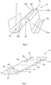
- Fig. 1 depicts a heat exchanger (3) comprising a plate stack (2) and at least one means (25).
- the heat exchanger (3) is provided with a number of inlet and outlet ports with port recesses (32-35) for a medium.
- the plate stack (2) comprises a number of plates (1) permanently connected to one another by a known connection method.
- Known connection methods are, inter alia, soldering, welding, adhesive and bonding.
- Fig. 2 depicts a plate (1) according to the invention.
- the plate (1) comprises first and second long sides (4 and 5), first and second short sides (6 and 7), a heat transfer surface (8) with a pattern (9) comprising ridges (10a-d) and valleys (11a-e).
- a first corner portion (14) is formed at the connection between the first short side (6) and the first long side (4).
- a second corner portion (15) is situated at the connection between the first short side (6) and the second long side (5).
- a first port region (12) is situated in the first corner portion (14).
- a second port region (13) is formed in the second corner portion (15).
- a central axis (18) extends transversely across the plate (1) between and perpendicular to the two long sides (4 and 5).
- the central axis (18) divides the plate (1) into two equal halves.
- the halves are mirror images to one another in shape, pattern and contour. This means that the plate (1) comprises in all four corner portions, four port regions, etc.
- this description refers only to said technical features pertaining to one half of the plate.
- the plate (1) is stacked in a plate stack (2, see Fig. 1 ) with similar plates (1). Every second plate (1) in said plate stack (2) is rotated 180° in a plane parallel with the heat transfer surface (8). Each plate (1) comprises an upper side and a lower side. All the plates (1) in the plate stack (2) are placed on one another with their respective undersides facing the same direction. Such stacking results in the top side of the pattern (9) of a first plate (1) abutting against the pattern (9) on the underside of a rotated similar second plate (1).
- the first port region (12) communicates with a number of ridges (10a-d) and valleys (11a-e).
- the ridges (10a-d) and valleys (11a-e) on the plate (1) on the respective sides of the central axis (18) are all in principle parallel with one another.
- a contact point (16a-d) is formed on the end portion of each of the respective ridges (10a-d) which are adjacent to the first port region (12). Said contact points (16a-d) are in principle situated at the same radial distance from the centre of the first port region (12). The contact points (16a-d) follow the extent of a circular arc (17) round the port region (12). The centre of the circular arc (17) is within the area of the first port region (12).
- Stacking two mutually adjacent plates (1) in said plate stack (2, see Fig. 1 ) will result in a first contact point (16a) on a first plate (1) abutting against the underside of a first valley (11a) on a rotated similar second plate (1) placed on said first plate (1).
- Second, third and fourth contact points (16b-d) will correspondingly abut against the underside of a second valley (11b) of the same plates (1) as in the case of the first contact point (16a) and the first valley (11a).
- a second ridge (10b) is connected to a third ridge (10c) by a first connection (24).
- the second valley (11b) is adjacent to the second ridge (10b), the third ridge (10c), the first ridge (10a) and the second port region (13).
- the second ridge (10b) extends between said first connection (24) and the first port region (12). The result is the formation of said second valley (11b) which not only runs round part of the second port region (13) but is also adjacent to the heat transfer surface (8) of the plate (1).
- the second valley (11b) follows initially the second ridge (10b) from the first port region (12) to the first connection (24).
- the valley (11b) is compelled to change direction in order thereafter to follow the third ridge (10c) to the second long side (5).
- the fact that the second valley (11b) runs round part of the second port region (13) results in the formation on its underside of an elongate area round part of said second port region (13).
- Said region (13) connects to the second, third and fourth contact points (16b-d).
- the ridges (10a-d) can be parallel with one another and said contact points can be situated on the ridges (10b-d) at in principle the same radial distance from the centre of the first port region (12). This makes it possible for there to be uneven stressing at respective contact points (16a-d) round the first port region (12).
- Fig. 3 depicts part of a pattern (9) in a plate (1, see Fig. 2 ) according to the invention.
- Fig. 3 depicts only one ridge (10) and one valley (11), whereas the plate (1) according to the invention comprises a number of ridges and valleys.
- the ridge (10) comprises a crest portion (21) and two side portions (22a, b).
- the respective side portions (22a, b) are connected to the crest portion (21).
- the valley (11) is connected to the crest portion (21) by the side portions (22a, b).
- the crest portion (21) has the same extent as the ridge (10) and the valley (11).
- Each ridge (10) varies in width along its extent so that the smaller the width of the ridge (10) the smaller the width of the crest portion (21).
- the radius of the arcuate edge portion (23a, b) varies correspondingly so that the smaller the width of the crest portion (21) the smaller the radius.
- the width of the respective valley (11) varies along its extent in a similar manner to the ridge (10) and its crest portion (21).
- each ridge (10) and valley (11) are parallel with one another on their respective sides of the central axis (18, see Fig. 2 ).
- the ridges (10) and the valleys (11) vary in width and hence in volume per unit width makes it possible to lead a medium to parts of the heat-transmitting surface of the plate (1) which in conventional plates are difficult to cause the medium to act upon.
- the fact that the volume per unit width is increased in the regions which are difficult to cause the medium to act upon makes it possible to utilise a larger surface on a plate (1) for heat transfer.
- Fig. 4 depicts a means (25).
- the means (25) has correspondingly the same outer periphery as a plate (1, see Fig. 1 ) stacked on similar plates (1) in a plate stack (2).
- the means (25) comprises a first surface (26), a second surface (27, not shown in the drawings) and port recesses (32-35).
- a first protrusion (28) and a second protrusion (29) are pressed in the first surface (26) on the respective sides of a second central axis (36).
- the position of this second central axis (36) corresponds to the central axis (18) of a plate (1, see Fig. 2 ) according to the invention.
- the respective protrusions (28, 29) stick out from the second surface (27, not shown in the drawings).
- the means (25) is placed on the first and/or the last plate (1) in the plate stack (2, see Fig. 1 ).
- the protrusions (28, 29) in the second surface (27, not shown in the drawings) are shaped to fit into the pattern (9, see Fig. 2 ) on an adjacent plate (1).
- the first protrusion (28) is inserted in the second valley (11b) in the plate (1).
- the second protrusion (29) is inserted in the fifth valley (11e). Both the second valley (11b) and the fifth valley (11e) communicate with the first port region (12).
- a plate stack (2) it is desirable to be able to reduce the amount of medium which accumulates during operation between the means (25) and the adjacent plate (1).
- the insertion of said protrusions (28, 29) in a number of the valleys (11b, 11e) which communicate with the first port region (12) prevents flow of medium in these valleys (11b, 11e) from said port region (12) to the second long side (5).
- the result is optimisation of the total heat transfer in the heat exchanger (3) in that medium which does not contribute to heat transfer is reduced.
Landscapes
- Engineering & Computer Science (AREA)
- Physics & Mathematics (AREA)
- Thermal Sciences (AREA)
- Mechanical Engineering (AREA)
- General Engineering & Computer Science (AREA)
- Heat-Exchange Devices With Radiators And Conduit Assemblies (AREA)
- Cooling Or The Like Of Semiconductors Or Solid State Devices (AREA)
Claims (5)
- Plaque de transfert de chaleur (1) destinée à constituer, avec d'autres plaques de transfert de chaleur similaires, une pile de plaques (2) avec des plaques connectées en permanence pour un échangeur de chaleur (3), ladite plaque de transfert de chaleur (1) comprenant un premier côté long (4) et un second côté long opposé (5), un premier côté court (6) et un second côté court opposé (7), une surface de transfert de chaleur (8) présentant un motif (9) d'arêtes (10) et de vallées (11), des première et seconde régions d'orifices (12 et 13), ladite première région d'orifice (12) étant située dans une première partie d'angle (14) formée à la réunion entre le premier côté long (4) et le premier côté court (6), ladite seconde région d'orifice (13) étant située dans une seconde partie d'angle (15) formée à la réunion entre le second côté long (5) et le premier côté court (6), et ladite première région d'orifice (12) étant raccordée à un certain nombre d'arêtes (10a à d) et de vallées (11a à e), lesdites arêtes (10a à d) et vallées (11a à e) présentent une ampleur continue depuis ladite première région d'orifice (12) en diagonale vers le second côté long (5), dans laquelle, lorsqu'une plaque adjacente similaire dans la pile de plaques est tournée de 180° dans un plan parallèle à la surface de transfert de chaleur, la plaque de transfert de chaleur (1) et la plaque adjacente tournées l'une par rapport à l'autre viennent en butée l'une contre l'autre par le biais de crêtes des arêtes et des parties inférieures des vallées, en formant donc des points de contact (16a à d) lors de la mise en butée des crêtes et vallées réciproquement adjacentes, formées lors de la butée entre des crêtes et vallées réciproquement adjacentes de plaques empilées sont situées sur lesdites arêtes (10a à d) à proximité directe de la première région d'orifice (12), lesdits points de contact (16a à d) sont ainsi positionnés de sorte qu'au moins un point de contact (16b, c) vienne joindre deux points de contact (16a, c, et 16b, d, respectivement), lesdits points de contact (16a à d) étant à la même distance radiale du centre de ladite première région d'orifice (12), dans laquelle, chaque arête (10a à d) présente une première ligne centrale (30) divisant l'ampleur des arêtes (10a à d) en deux parties égales, dans lequel chaque vallée (11a à e) présente une seconde ligne centrale (31) divisant l'ampleur des valeurs (lia à e) en deux parties égales, dans lequel la seconde vallée (11b) desdites vallées (lia à e) s'étend le long de la deuxième arête (10b) et de la troisième arête (10c), caractérisé en ce que deux arêtes adjacentes (10a à d) forment entre elles une vallée (11a à e) dont la largeur entre les arêtes (10a à d) varie le long de l'ampleur de ladite vallée (10a à d), dans lequel la plaque de transfert de chaleur (1) présente un axe central (18) parallèle aux côtés courts respectifs (6, 7) et est symétrique relativement à l'axe central (18) de sorte que chaque arête (10a à d) et vallée (lia à e) comprimée dans la plaque de transfert de chaleur (1) corresponde en forme et en position à une arête et à une vallée de l'autre côté de l'axe central (18), dans lequel les premières lignes centrales (30) dans les arêtes respectives du même côté de l'axe central (18) sont parallèles les unes par rapport aux autres, dans lequel les secondes lignes centrales respectives (31) dans les vallées respectives sont parallèles aux secondes lignes centrales des vallées respectives du même côté de l'axe central (18), la partie de crête (21) étant raccordée à chaque partie latérale (22a, b) par une partie de bord arqué (23a, b), dont le rayon varie le long de l'ampleur des arêtes (10a à d) d'une manière associée à la largeur de la partie de crête (21), de sorte que plus la largeur de la partie de crête est petite (21), plus le rayon est petit.
- Plaque de transfert de chaleur (1) selon la revendication 1, caractérisée en ce que les points de contact (16a à d) situés sur les parties d'extrémité des arêtes respectives (10a à d), lesdites parties d'extrémité (10a à d) joignent ladite région d'orifice (12), sont positionnées de telle sorte que les points de contact respectifs (16a à d) sont adjacents à, ou coupés par, l'ampleur d'un arc circulaire (17).
- Plaque de transfert de chaleur (1) selon la revendication 1, caractérisée en ce qu'une première arête (10a) et une deuxième arête (10b) forment entre elles une seconde vallée (11b), ladite première arête (10a) s'étendant entre les deux régions d'orifice (12 et 13) et ladite vallée (11b) s'étendant d'une région d'orifice (12) sur un long côté (4) au second long côté opposé (5).
- Plaque de transfert de chaleur (1) selon la revendication 3, caractérisée en ce que la deuxième arête (10b) est raccordée à une troisième arête (10c) par une première connexion (24), moyennant quoi une troisième vallée (11c) est formée entre lesdites deuxième et troisième arêtes (10b et c), ladite troisième vallée (11c) présente une extrémité ouverte et une extrémité fermée.
- Échangeur de chaleur à plaque comprenant des plaques de transfert de chaleur similaires jointes de manière permanente selon l'une quelconque des revendications 1 à 4.
Priority Applications (1)
| Application Number | Priority Date | Filing Date | Title |
|---|---|---|---|
| SI200632342T SI1963771T1 (sl) | 2005-12-22 | 2006-12-21 | Plošča za prenos toplote ploščnega toplotnega izmenjevalnika, ki zagotavlja enako porazdelitev bremena v priključnih območjih |
Applications Claiming Priority (2)
| Application Number | Priority Date | Filing Date | Title |
|---|---|---|---|
| SE0502877A SE531472C2 (sv) | 2005-12-22 | 2005-12-22 | Värmeväxlare med värmeöverföringsplatta med jämn lastfördelning på kontaktpunkter vid portområden |
| PCT/SE2006/001469 WO2007073304A1 (fr) | 2005-12-22 | 2006-12-21 | Plaque de transfert de chaleur pour echangeur de chaleur sous forme de plaques presentant une repartition uniforme de charge dans les zones a orifice |
Publications (3)
| Publication Number | Publication Date |
|---|---|
| EP1963771A1 EP1963771A1 (fr) | 2008-09-03 |
| EP1963771A4 EP1963771A4 (fr) | 2013-05-29 |
| EP1963771B1 true EP1963771B1 (fr) | 2019-07-10 |
Family
ID=38188934
Family Applications (2)
| Application Number | Title | Priority Date | Filing Date |
|---|---|---|---|
| EP06824534.9A Active EP1963770B1 (fr) | 2005-12-22 | 2006-12-21 | Moyens associés a un échangeur de chaleur sous forme de plaques |
| EP06835884.5A Active EP1963771B1 (fr) | 2005-12-22 | 2006-12-21 | Plaque de transfert de chaleur pour échangeur de chaleur sous forme de plaques présentant une répartition uniforme de charge dans les zones à orifice |
Family Applications Before (1)
| Application Number | Title | Priority Date | Filing Date |
|---|---|---|---|
| EP06824534.9A Active EP1963770B1 (fr) | 2005-12-22 | 2006-12-21 | Moyens associés a un échangeur de chaleur sous forme de plaques |
Country Status (14)
| Country | Link |
|---|---|
| US (2) | US20090008073A1 (fr) |
| EP (2) | EP1963770B1 (fr) |
| JP (2) | JP5037524B2 (fr) |
| KR (2) | KR101249174B1 (fr) |
| CN (2) | CN101346598B (fr) |
| AU (2) | AU2006327322B2 (fr) |
| BR (2) | BRPI0620443A2 (fr) |
| CA (2) | CA2634318A1 (fr) |
| DK (2) | DK1963770T3 (fr) |
| ES (2) | ES2744813T3 (fr) |
| RU (2) | RU2411436C2 (fr) |
| SE (1) | SE531472C2 (fr) |
| SI (2) | SI1963770T1 (fr) |
| WO (2) | WO2007073305A1 (fr) |
Cited By (2)
| Publication number | Priority date | Publication date | Assignee | Title |
|---|---|---|---|---|
| US11226163B2 (en) | 2017-04-26 | 2022-01-18 | Alfa Laval Corporate Ab | Heat transfer plate and heat exchanger comprising a plurality of such heat transfer plates |
| US11774191B2 (en) | 2017-10-05 | 2023-10-03 | Alfa Laval Corporate Ab | Heat transfer plate and a plate pack for a heat exchanger comprising a plurality of such heat transfer plates |
Families Citing this family (18)
| Publication number | Priority date | Publication date | Assignee | Title |
|---|---|---|---|---|
| SE533310C2 (sv) * | 2008-11-12 | 2010-08-24 | Alfa Laval Corp Ab | Värmeväxlarplatta och värmeväxlare innefattande värmeväxlarplattor |
| SE533205C2 (sv) | 2008-12-03 | 2010-07-20 | Alfa Laval Corp Ab | Värmeväxlare |
| DE102009058676A1 (de) * | 2009-12-16 | 2011-06-22 | Behr GmbH & Co. KG, 70469 | Wärmetauscher |
| JP5932777B2 (ja) * | 2011-04-18 | 2016-06-08 | 三菱電機株式会社 | プレート式熱交換器及びヒートポンプ装置 |
| EP2741041B1 (fr) | 2011-07-13 | 2019-09-11 | Mitsubishi Electric Corporation | Échangeur de chaleur de type à plaques et dispositif de pompe à chaleur |
| ES2749507T3 (es) * | 2012-06-14 | 2020-03-20 | Alfa Laval Corp Ab | Un intercambiador de calor de placas con medios de inyección |
| US20150034285A1 (en) * | 2013-08-01 | 2015-02-05 | Hamilton Sundstrand Corporation | High-pressure plate heat exchanger |
| SI3062949T2 (sl) * | 2013-10-29 | 2023-08-31 | Swep International Ab | Postopek trdega lotanja ploščatega izmenjevalnika toplote s pomočjo s sitotiskom nanešenega lota |
| EP3080541B1 (fr) * | 2013-12-10 | 2019-05-08 | SWEP International AB | Échangeur thermique avec écoulement amélioré |
| EP3078929B1 (fr) * | 2015-04-07 | 2018-01-31 | Alfa Laval Corporate AB | Procédé pour la production d'un échangeur de chaleur à plaques |
| EP3093602B1 (fr) | 2015-05-11 | 2020-04-15 | Alfa Laval Corporate AB | Plaque d'échangeur de chaleur et échangeur de chaleur à plaques |
| EP3527320B1 (fr) * | 2016-03-31 | 2020-12-23 | Alfa Laval Corporate AB | Procédé d'assemblage de plaques de transfert de chaleur d'un échangeur de chaleur à plaques |
| US20180100706A1 (en) * | 2016-10-11 | 2018-04-12 | Climate Master, Inc. | Enhanced heat exchanger |
| SI3800422T1 (sl) * | 2017-03-10 | 2023-12-29 | Alfa Laval Corporate Ab | Plošča za napravo za izmenjevanje toplote |
| US10591220B2 (en) | 2017-08-31 | 2020-03-17 | Dana Canada Corporation | Multi-fluid heat exchanger |
| JP7001413B2 (ja) * | 2017-09-28 | 2022-01-19 | 株式会社日阪製作所 | プレート式熱交換器 |
| EP3587984B1 (fr) * | 2018-06-28 | 2020-11-11 | Alfa Laval Corporate AB | Plaque et joint de transfert de chaleur |
| SE544426C2 (en) | 2019-04-03 | 2022-05-24 | Alfa Laval Corp Ab | A heat exchanger plate, and a plate heat exchanger |
Family Cites Families (56)
| Publication number | Priority date | Publication date | Assignee | Title |
|---|---|---|---|---|
| US55149A (en) * | 1866-05-29 | Improvement in surface-condensers | ||
| US1826344A (en) * | 1930-09-23 | 1931-10-06 | Res & Dev Corp | Heat exchange element |
| DE1601216B2 (de) * | 1967-11-03 | 1971-06-16 | Linde Ag, 6200 Wiesbaden | Blechtafel fuer platten waermetauscher mit einem stapel solcher blechtafeln |
| US3537165A (en) * | 1968-06-26 | 1970-11-03 | Air Preheater | Method of making a plate-type heat exchanger |
| US3661203A (en) * | 1969-11-21 | 1972-05-09 | Parkson Corp | Plates for directing the flow of fluids |
| GB1298240A (en) * | 1970-10-21 | 1972-11-29 | Apv Co Ltd | Improvements in or relating to plate heat exchangers |
| IT1055235B (it) * | 1976-02-12 | 1981-12-21 | Fischer H | Scambiatore di calore a piastre formato da piastre aventi forme diverse |
| SE7601607L (sv) * | 1976-02-12 | 1977-08-13 | Atomenergi Ab | Plattvermevexlare |
| SE423750B (sv) | 1977-01-14 | 1982-05-24 | Munters Ab Carl | Anordning vid vermevexlare for sensibel och/eller latent vermeoverforing |
| SE415928B (sv) * | 1979-01-17 | 1980-11-10 | Alfa Laval Ab | Plattvermevexlare |
| US4249597A (en) | 1979-05-07 | 1981-02-10 | General Motors Corporation | Plate type heat exchanger |
| SE431793B (sv) * | 1980-01-09 | 1984-02-27 | Alfa Laval Ab | Plattvermevexlare med korrugerade plattor |
| US4442886A (en) * | 1982-04-19 | 1984-04-17 | North Atlantic Technologies, Inc. | Floating plate heat exchanger |
| JPS59195389U (ja) * | 1983-06-07 | 1984-12-25 | 東洋ラジエーター株式会社 | 熱交換器の放熱体 |
| DE3622316C1 (de) * | 1986-07-03 | 1988-01-28 | Schmidt W Gmbh Co Kg | Plattenwaermeaustauscher |
| JPH0326231A (ja) * | 1989-06-23 | 1991-02-04 | Fukuda Denshi Co Ltd | レコーダ制御方法 |
| US5056590A (en) * | 1990-03-30 | 1991-10-15 | The Cherry-Burrell Corporation | Plate heat exchanger |
| RU1800255C (ru) | 1990-04-09 | 1993-03-07 | Одесский институт низкотемпературной техники и энергетики | Матричный теплообменник |
| SE505225C2 (sv) * | 1993-02-19 | 1997-07-21 | Alfa Laval Thermal Ab | Plattvärmeväxlare och platta härför |
| IT1263611B (it) * | 1993-02-19 | 1996-08-27 | Giannoni Srl | Scambiatore di calore a piastre |
| US5462113A (en) * | 1994-06-20 | 1995-10-31 | Flatplate, Inc. | Three-circuit stacked plate heat exchanger |
| SE9502135D0 (sv) * | 1995-06-13 | 1995-06-13 | Tetra Laval Holdings & Finance | Plattvärmeväxlare |
| SE504868C2 (sv) | 1995-10-23 | 1997-05-20 | Swep International Ab | Plattvärmeväxlare med ändplatta med pressat mönster |
| JP3302869B2 (ja) * | 1995-11-15 | 2002-07-15 | 株式会社荏原製作所 | プレート式熱交換器及びその製造方法 |
| SE9504586D0 (sv) * | 1995-12-21 | 1995-12-21 | Tetra Laval Holdings & Finance | Plattvärmeväxlare |
| JP3026231U (ja) | 1995-12-22 | 1996-07-02 | 東洋ラジエーター株式会社 | オイルクーラ |
| US5964280A (en) * | 1996-07-16 | 1999-10-12 | Modine Manufacturing Company | Multiple fluid path plate heat exchanger |
| AT407920B (de) * | 1997-03-25 | 2001-07-25 | Ktm Kuehler Gmbh | Plattenwärmetauscher, insbesondere ölkühler |
| JP3292128B2 (ja) * | 1998-02-27 | 2002-06-17 | ダイキン工業株式会社 | プレート型熱交換器 |
| JPH11287582A (ja) * | 1998-03-31 | 1999-10-19 | Hisaka Works Ltd | プレート式熱交換器 |
| CA2260890A1 (fr) * | 1999-02-05 | 2000-08-05 | Long Manufacturing Ltd. | Echangeurs de chaleur fermes |
| DE19959780B4 (de) * | 1999-04-12 | 2004-11-25 | Rehberg, Peter, Dipl.-Ing. | Plattenwärmeübertrager |
| FR2795167B1 (fr) * | 1999-06-21 | 2001-09-14 | Valeo Thermique Moteur Sa | Echangeur de chaleur a plaques, notamment pour refroidir une huile d'un vehicule automobile |
| DE19948222C2 (de) * | 1999-10-07 | 2002-11-07 | Xcellsis Gmbh | Plattenwärmetauscher |
| FR2803025B1 (fr) * | 1999-12-22 | 2002-05-03 | Mer Joseph Le | Echangeur thermique a plaques, a clapet de decharge integre |
| SE515467C2 (sv) * | 1999-12-23 | 2001-08-13 | Alfa Laval Ab | Plattvärmeväxlare med minst en platta försedd med ett trågformat parti för bildande av ett avtätat utrymme. |
| JP2001248996A (ja) * | 2000-03-08 | 2001-09-14 | Hitachi Ltd | プレート式熱交換器 |
| DE10024888B4 (de) * | 2000-05-16 | 2008-10-16 | Gea Wtt Gmbh | Plattenwärmeübertrager mit Kältemittelverteiler |
| JP3448265B2 (ja) * | 2000-07-27 | 2003-09-22 | 昭 藤山 | チタン製プレート式熱交換器の製造方法 |
| JP2002081883A (ja) * | 2000-09-08 | 2002-03-22 | Hitachi Ltd | プレート式熱交換器およびそれを用いた吸収式冷凍機 |
| CN1333229C (zh) * | 2000-12-28 | 2007-08-22 | 昭和电工株式会社 | 层状热交换器 |
| SE518248C2 (sv) * | 2001-01-31 | 2002-09-17 | Alfa Laval Ab | Plattvärmeväxlare |
| CN2554586Y (zh) * | 2002-07-29 | 2003-06-04 | 北京海淀永大机电设备制造有限责任公司 | 大截面板式换热器 |
| DE10304733A1 (de) * | 2003-02-06 | 2004-08-19 | Modine Manufacturing Co., Racine | Plattenwärmetauscher |
| JP2005009828A (ja) * | 2003-06-20 | 2005-01-13 | Calsonic Kansei Corp | 熱交換器 |
| BRPI0413194B1 (pt) * | 2003-08-01 | 2019-04-30 | Behr Gmbh & Co. Kg | Trocador de calor, especialmente radiador para óleo de veículos automotores |
| JP4210185B2 (ja) | 2003-09-05 | 2009-01-14 | スズキ株式会社 | シートベルト装置 |
| DE102004003790A1 (de) * | 2004-01-23 | 2005-08-11 | Behr Gmbh & Co. Kg | Wärmetauscher, insbesondere Öl-/Kühlmittel-Kühler |
| WO2005088223A1 (fr) * | 2004-03-11 | 2005-09-22 | Behr Gmbh & Co. Kg | Echangeur thermique a empilement de disques |
| SE526831C2 (sv) * | 2004-03-12 | 2005-11-08 | Alfa Laval Corp Ab | Värmeväxlarplatta och plattpaket |
| JP2005291671A (ja) * | 2004-04-05 | 2005-10-20 | Calsonic Kansei Corp | 積層型熱交換器 |
| SE527716C2 (sv) * | 2004-04-08 | 2006-05-23 | Swep Int Ab | Plattvärmeväxlare |
| SE528275C2 (sv) * | 2005-02-15 | 2006-10-10 | Alfa Laval Corp Ab | Värmeöverföringsplatta med styrorgan samt värmeväxlare som innefattar sådana plattor |
| SE528886C2 (sv) * | 2005-08-26 | 2007-03-06 | Swep Int Ab | Ändplatta |
| SE530011C2 (sv) * | 2006-06-05 | 2008-02-05 | Alfa Laval Corp Ab | Värmeväxlarplatta och plattvärmeväxlare |
| EP2054679A4 (fr) * | 2006-08-23 | 2013-01-23 | Alfa Laval Corp Ab | Échangeur de chaleur à plaques et installation d'échangeur de chaleur |
-
2005
- 2005-12-22 SE SE0502877A patent/SE531472C2/sv unknown
-
2006
- 2006-12-21 JP JP2008547170A patent/JP5037524B2/ja active Active
- 2006-12-21 BR BRPI0620443-0A patent/BRPI0620443A2/pt not_active IP Right Cessation
- 2006-12-21 US US12/097,656 patent/US20090008073A1/en not_active Abandoned
- 2006-12-21 CA CA002634318A patent/CA2634318A1/fr not_active Abandoned
- 2006-12-21 AU AU2006327322A patent/AU2006327322B2/en active Active
- 2006-12-21 WO PCT/SE2006/001470 patent/WO2007073305A1/fr active Application Filing
- 2006-12-21 ES ES06835884T patent/ES2744813T3/es active Active
- 2006-12-21 EP EP06824534.9A patent/EP1963770B1/fr active Active
- 2006-12-21 KR KR1020087017737A patent/KR101249174B1/ko active IP Right Grant
- 2006-12-21 AU AU2006327321A patent/AU2006327321B2/en active Active
- 2006-12-21 RU RU2008130127/06A patent/RU2411436C2/ru active
- 2006-12-21 DK DK06824534.9T patent/DK1963770T3/en active
- 2006-12-21 ES ES06824534.9T patent/ES2687198T3/es active Active
- 2006-12-21 SI SI200632274T patent/SI1963770T1/sl unknown
- 2006-12-21 CN CN2006800487463A patent/CN101346598B/zh active Active
- 2006-12-21 CA CA2634314A patent/CA2634314C/fr active Active
- 2006-12-21 EP EP06835884.5A patent/EP1963771B1/fr active Active
- 2006-12-21 US US12/097,597 patent/US8109326B2/en active Active
- 2006-12-21 RU RU2008130129/06A patent/RU2413916C2/ru active
- 2006-12-21 JP JP2008547171A patent/JP4981063B2/ja active Active
- 2006-12-21 SI SI200632342T patent/SI1963771T1/sl unknown
- 2006-12-21 BR BRPI0619643A patent/BRPI0619643B1/pt active IP Right Grant
- 2006-12-21 DK DK06835884.5T patent/DK1963771T3/da active
- 2006-12-21 KR KR1020087017738A patent/KR101300946B1/ko active IP Right Grant
- 2006-12-21 CN CN2006800486761A patent/CN101346597B/zh active Active
- 2006-12-21 WO PCT/SE2006/001469 patent/WO2007073304A1/fr active Application Filing
Non-Patent Citations (1)
| Title |
|---|
| None * |
Cited By (2)
| Publication number | Priority date | Publication date | Assignee | Title |
|---|---|---|---|---|
| US11226163B2 (en) | 2017-04-26 | 2022-01-18 | Alfa Laval Corporate Ab | Heat transfer plate and heat exchanger comprising a plurality of such heat transfer plates |
| US11774191B2 (en) | 2017-10-05 | 2023-10-03 | Alfa Laval Corporate Ab | Heat transfer plate and a plate pack for a heat exchanger comprising a plurality of such heat transfer plates |
Also Published As
Similar Documents
| Publication | Publication Date | Title |
|---|---|---|
| EP1963771B1 (fr) | Plaque de transfert de chaleur pour échangeur de chaleur sous forme de plaques présentant une répartition uniforme de charge dans les zones à orifice | |
| KR101445474B1 (ko) | 열교환판과 판형 열교환기 | |
| EP2084481B1 (fr) | Échangeur de chaleur à plaque | |
| JP4584524B2 (ja) | 熱伝達プレートおよびプレート型熱交換器に用いるプレート充填体 | |
| US4423772A (en) | Plate heat exchanger | |
| WO2007004939A1 (fr) | Plaque d’échange thermique, paire de deux plaques d’échange thermique et ensemble de plaques pour échangeur thermique à plaques | |
| EP1723376A1 (fr) | Plaque d'echangeur thermique et bloc de plaques | |
| EP1456595B1 (fr) | Plaque d'echangeur thermique, groupe de plaques et echangeur thermique a plaques | |
| EP4089359A1 (fr) | Plaque pour un échangeur de chaleur à plaques avec des ondulations asymétriques | |
| EP1456594B1 (fr) | Plaque d'echangeur thermique | |
| JP2006317029A (ja) | 熱交換ユニット | |
| CN108700388B (zh) | 用于板式热交换器的热交换器板和板式热交换器 | |
| EP1813901A2 (fr) | Plaque d'échange de chaleur | |
| JP2001280887A (ja) | プレート式熱交換器 |
Legal Events
| Date | Code | Title | Description |
|---|---|---|---|
| PUAI | Public reference made under article 153(3) epc to a published international application that has entered the european phase |
Free format text: ORIGINAL CODE: 0009012 |
|
| 17P | Request for examination filed |
Effective date: 20080526 |
|
| AK | Designated contracting states |
Kind code of ref document: A1 Designated state(s): AT BE BG CH CY CZ DE DK EE ES FI FR GB GR HU IE IS IT LI LT LU LV MC NL PL PT RO SE SI SK TR |
|
| DAX | Request for extension of the european patent (deleted) | ||
| RIC1 | Information provided on ipc code assigned before grant |
Ipc: F28F 3/08 20060101AFI20130418BHEP Ipc: F28D 9/00 20060101ALI20130418BHEP Ipc: F28F 9/02 20060101ALI20130418BHEP Ipc: F28F 3/04 20060101ALI20130418BHEP |
|
| A4 | Supplementary search report drawn up and despatched |
Effective date: 20130426 |
|
| RIC1 | Information provided on ipc code assigned before grant |
Ipc: F28F 3/04 20060101ALI20130422BHEP Ipc: F28D 9/00 20060101ALI20130422BHEP Ipc: F28F 9/02 20060101ALI20130422BHEP Ipc: F28F 3/08 20060101AFI20130422BHEP |
|
| 17Q | First examination report despatched |
Effective date: 20150309 |
|
| STAA | Information on the status of an ep patent application or granted ep patent |
Free format text: STATUS: EXAMINATION IS IN PROGRESS |
|
| GRAP | Despatch of communication of intention to grant a patent |
Free format text: ORIGINAL CODE: EPIDOSNIGR1 |
|
| STAA | Information on the status of an ep patent application or granted ep patent |
Free format text: STATUS: GRANT OF PATENT IS INTENDED |
|
| INTG | Intention to grant announced |
Effective date: 20190312 |
|
| GRAS | Grant fee paid |
Free format text: ORIGINAL CODE: EPIDOSNIGR3 |
|
| GRAA | (expected) grant |
Free format text: ORIGINAL CODE: 0009210 |
|
| STAA | Information on the status of an ep patent application or granted ep patent |
Free format text: STATUS: THE PATENT HAS BEEN GRANTED |
|
| AK | Designated contracting states |
Kind code of ref document: B1 Designated state(s): AT BE BG CH CY CZ DE DK EE ES FI FR GB GR HU IE IS IT LI LT LU LV MC NL PL PT RO SE SI SK TR |
|
| REG | Reference to a national code |
Ref country code: GB Ref legal event code: FG4D |
|
| RIN1 | Information on inventor provided before grant (corrected) |
Inventor name: GUDMUNDSSON, THORD Inventor name: LARSSON, HAKAN Inventor name: DRAKARVE, KERSTIN |
|
| REG | Reference to a national code |
Ref country code: CH Ref legal event code: EP Ref country code: AT Ref legal event code: REF Ref document number: 1154042 Country of ref document: AT Kind code of ref document: T Effective date: 20190715 |
|
| REG | Reference to a national code |
Ref country code: DE Ref legal event code: R096 Ref document number: 602006058305 Country of ref document: DE |
|
| REG | Reference to a national code |
Ref country code: IE Ref legal event code: FG4D |
|
| REG | Reference to a national code |
Ref country code: DK Ref legal event code: T3 Effective date: 20191011 |
|
| REG | Reference to a national code |
Ref country code: SE Ref legal event code: TRGR |
|
| REG | Reference to a national code |
Ref country code: SK Ref legal event code: T3 Ref document number: E 31993 Country of ref document: SK |
|
| REG | Reference to a national code |
Ref country code: NL Ref legal event code: MP Effective date: 20190710 |
|
| REG | Reference to a national code |
Ref country code: LT Ref legal event code: MG4D |
|
| REG | Reference to a national code |
Ref country code: AT Ref legal event code: MK05 Ref document number: 1154042 Country of ref document: AT Kind code of ref document: T Effective date: 20190710 |
|
| PG25 | Lapsed in a contracting state [announced via postgrant information from national office to epo] |
Ref country code: FI Free format text: LAPSE BECAUSE OF FAILURE TO SUBMIT A TRANSLATION OF THE DESCRIPTION OR TO PAY THE FEE WITHIN THE PRESCRIBED TIME-LIMIT Effective date: 20190710 Ref country code: NL Free format text: LAPSE BECAUSE OF FAILURE TO SUBMIT A TRANSLATION OF THE DESCRIPTION OR TO PAY THE FEE WITHIN THE PRESCRIBED TIME-LIMIT Effective date: 20190710 Ref country code: AT Free format text: LAPSE BECAUSE OF FAILURE TO SUBMIT A TRANSLATION OF THE DESCRIPTION OR TO PAY THE FEE WITHIN THE PRESCRIBED TIME-LIMIT Effective date: 20190710 Ref country code: LT Free format text: LAPSE BECAUSE OF FAILURE TO SUBMIT A TRANSLATION OF THE DESCRIPTION OR TO PAY THE FEE WITHIN THE PRESCRIBED TIME-LIMIT Effective date: 20190710 Ref country code: BG Free format text: LAPSE BECAUSE OF FAILURE TO SUBMIT A TRANSLATION OF THE DESCRIPTION OR TO PAY THE FEE WITHIN THE PRESCRIBED TIME-LIMIT Effective date: 20191010 Ref country code: PT Free format text: LAPSE BECAUSE OF FAILURE TO SUBMIT A TRANSLATION OF THE DESCRIPTION OR TO PAY THE FEE WITHIN THE PRESCRIBED TIME-LIMIT Effective date: 20191111 |
|
| REG | Reference to a national code |
Ref country code: ES Ref legal event code: FG2A Ref document number: 2744813 Country of ref document: ES Kind code of ref document: T3 Effective date: 20200226 |
|
| PG25 | Lapsed in a contracting state [announced via postgrant information from national office to epo] |
Ref country code: GR Free format text: LAPSE BECAUSE OF FAILURE TO SUBMIT A TRANSLATION OF THE DESCRIPTION OR TO PAY THE FEE WITHIN THE PRESCRIBED TIME-LIMIT Effective date: 20191011 Ref country code: LV Free format text: LAPSE BECAUSE OF FAILURE TO SUBMIT A TRANSLATION OF THE DESCRIPTION OR TO PAY THE FEE WITHIN THE PRESCRIBED TIME-LIMIT Effective date: 20190710 Ref country code: IS Free format text: LAPSE BECAUSE OF FAILURE TO SUBMIT A TRANSLATION OF THE DESCRIPTION OR TO PAY THE FEE WITHIN THE PRESCRIBED TIME-LIMIT Effective date: 20191110 |
|
| PG25 | Lapsed in a contracting state [announced via postgrant information from national office to epo] |
Ref country code: TR Free format text: LAPSE BECAUSE OF FAILURE TO SUBMIT A TRANSLATION OF THE DESCRIPTION OR TO PAY THE FEE WITHIN THE PRESCRIBED TIME-LIMIT Effective date: 20190710 |
|
| PG25 | Lapsed in a contracting state [announced via postgrant information from national office to epo] |
Ref country code: PL Free format text: LAPSE BECAUSE OF FAILURE TO SUBMIT A TRANSLATION OF THE DESCRIPTION OR TO PAY THE FEE WITHIN THE PRESCRIBED TIME-LIMIT Effective date: 20190710 Ref country code: EE Free format text: LAPSE BECAUSE OF FAILURE TO SUBMIT A TRANSLATION OF THE DESCRIPTION OR TO PAY THE FEE WITHIN THE PRESCRIBED TIME-LIMIT Effective date: 20190710 Ref country code: RO Free format text: LAPSE BECAUSE OF FAILURE TO SUBMIT A TRANSLATION OF THE DESCRIPTION OR TO PAY THE FEE WITHIN THE PRESCRIBED TIME-LIMIT Effective date: 20190710 |
|
| PG25 | Lapsed in a contracting state [announced via postgrant information from national office to epo] |
Ref country code: CZ Free format text: LAPSE BECAUSE OF FAILURE TO SUBMIT A TRANSLATION OF THE DESCRIPTION OR TO PAY THE FEE WITHIN THE PRESCRIBED TIME-LIMIT Effective date: 20190710 Ref country code: IS Free format text: LAPSE BECAUSE OF FAILURE TO SUBMIT A TRANSLATION OF THE DESCRIPTION OR TO PAY THE FEE WITHIN THE PRESCRIBED TIME-LIMIT Effective date: 20200224 |
|
| REG | Reference to a national code |
Ref country code: DE Ref legal event code: R097 Ref document number: 602006058305 Country of ref document: DE |
|
| PLBE | No opposition filed within time limit |
Free format text: ORIGINAL CODE: 0009261 |
|
| STAA | Information on the status of an ep patent application or granted ep patent |
Free format text: STATUS: NO OPPOSITION FILED WITHIN TIME LIMIT |
|
| PG2D | Information on lapse in contracting state deleted |
Ref country code: IS |
|
| REG | Reference to a national code |
Ref country code: CH Ref legal event code: PL |
|
| 26N | No opposition filed |
Effective date: 20200603 |
|
| REG | Reference to a national code |
Ref country code: BE Ref legal event code: MM Effective date: 20191231 |
|
| PG25 | Lapsed in a contracting state [announced via postgrant information from national office to epo] |
Ref country code: MC Free format text: LAPSE BECAUSE OF FAILURE TO SUBMIT A TRANSLATION OF THE DESCRIPTION OR TO PAY THE FEE WITHIN THE PRESCRIBED TIME-LIMIT Effective date: 20190710 |
|
| PG25 | Lapsed in a contracting state [announced via postgrant information from national office to epo] |
Ref country code: LU Free format text: LAPSE BECAUSE OF NON-PAYMENT OF DUE FEES Effective date: 20191221 Ref country code: IE Free format text: LAPSE BECAUSE OF NON-PAYMENT OF DUE FEES Effective date: 20191221 |
|
| PG25 | Lapsed in a contracting state [announced via postgrant information from national office to epo] |
Ref country code: LI Free format text: LAPSE BECAUSE OF NON-PAYMENT OF DUE FEES Effective date: 20191231 Ref country code: BE Free format text: LAPSE BECAUSE OF NON-PAYMENT OF DUE FEES Effective date: 20191231 Ref country code: CH Free format text: LAPSE BECAUSE OF NON-PAYMENT OF DUE FEES Effective date: 20191231 |
|
| PG25 | Lapsed in a contracting state [announced via postgrant information from national office to epo] |
Ref country code: CY Free format text: LAPSE BECAUSE OF FAILURE TO SUBMIT A TRANSLATION OF THE DESCRIPTION OR TO PAY THE FEE WITHIN THE PRESCRIBED TIME-LIMIT Effective date: 20190710 |
|
| PG25 | Lapsed in a contracting state [announced via postgrant information from national office to epo] |
Ref country code: HU Free format text: LAPSE BECAUSE OF FAILURE TO SUBMIT A TRANSLATION OF THE DESCRIPTION OR TO PAY THE FEE WITHIN THE PRESCRIBED TIME-LIMIT; INVALID AB INITIO Effective date: 20061221 |
|
| P01 | Opt-out of the competence of the unified patent court (upc) registered |
Effective date: 20230412 |
|
| PGFP | Annual fee paid to national office [announced via postgrant information from national office to epo] |
Ref country code: SK Payment date: 20231113 Year of fee payment: 18 |
|
| PGFP | Annual fee paid to national office [announced via postgrant information from national office to epo] |
Ref country code: GB Payment date: 20231102 Year of fee payment: 18 |
|
| PGFP | Annual fee paid to national office [announced via postgrant information from national office to epo] |
Ref country code: SI Payment date: 20231025 Year of fee payment: 18 Ref country code: SE Payment date: 20231110 Year of fee payment: 18 Ref country code: IT Payment date: 20231110 Year of fee payment: 18 Ref country code: FR Payment date: 20231108 Year of fee payment: 18 Ref country code: DK Payment date: 20231215 Year of fee payment: 18 Ref country code: DE Payment date: 20231024 Year of fee payment: 18 |
|
| PGFP | Annual fee paid to national office [announced via postgrant information from national office to epo] |
Ref country code: ES Payment date: 20240112 Year of fee payment: 18 |