EP1961616A2 - Befestigungsvorrichtung - Google Patents
Befestigungsvorrichtung Download PDFInfo
- Publication number
- EP1961616A2 EP1961616A2 EP08001204A EP08001204A EP1961616A2 EP 1961616 A2 EP1961616 A2 EP 1961616A2 EP 08001204 A EP08001204 A EP 08001204A EP 08001204 A EP08001204 A EP 08001204A EP 1961616 A2 EP1961616 A2 EP 1961616A2
- Authority
- EP
- European Patent Office
- Prior art keywords
- fastening
- fastening device
- module carrier
- head part
- pin
- Prior art date
- Legal status (The legal status is an assumption and is not a legal conclusion. Google has not performed a legal analysis and makes no representation as to the accuracy of the status listed.)
- Granted
Links
- 238000007789 sealing Methods 0.000 claims description 6
- 230000002093 peripheral effect Effects 0.000 claims description 2
- 230000004308 accommodation Effects 0.000 abstract 1
- 239000000969 carrier Substances 0.000 description 2
- 238000009434 installation Methods 0.000 description 2
- 208000012886 Vertigo Diseases 0.000 description 1
- AZDRQVAHHNSJOQ-UHFFFAOYSA-N alumane Chemical group [AlH3] AZDRQVAHHNSJOQ-UHFFFAOYSA-N 0.000 description 1
- 230000001066 destructive effect Effects 0.000 description 1
- 238000001746 injection moulding Methods 0.000 description 1
- 238000004519 manufacturing process Methods 0.000 description 1
- 229910052751 metal Inorganic materials 0.000 description 1
- 239000002184 metal Substances 0.000 description 1
Images


Classifications
-
- F—MECHANICAL ENGINEERING; LIGHTING; HEATING; WEAPONS; BLASTING
- F16—ENGINEERING ELEMENTS AND UNITS; GENERAL MEASURES FOR PRODUCING AND MAINTAINING EFFECTIVE FUNCTIONING OF MACHINES OR INSTALLATIONS; THERMAL INSULATION IN GENERAL
- F16B—DEVICES FOR FASTENING OR SECURING CONSTRUCTIONAL ELEMENTS OR MACHINE PARTS TOGETHER, e.g. NAILS, BOLTS, CIRCLIPS, CLAMPS, CLIPS OR WEDGES; JOINTS OR JOINTING
- F16B19/00—Bolts without screw-thread; Pins, including deformable elements; Rivets
- F16B19/04—Rivets; Spigots or the like fastened by riveting
- F16B19/08—Hollow rivets; Multi-part rivets
- F16B19/10—Hollow rivets; Multi-part rivets fastened by expanding mechanically
- F16B19/1027—Multi-part rivets
- F16B19/1036—Blind rivets
- F16B19/1081—Blind rivets fastened by a drive-pin
-
- B—PERFORMING OPERATIONS; TRANSPORTING
- B60—VEHICLES IN GENERAL
- B60R—VEHICLES, VEHICLE FITTINGS, OR VEHICLE PARTS, NOT OTHERWISE PROVIDED FOR
- B60R11/00—Arrangements for holding or mounting articles, not otherwise provided for
-
- B—PERFORMING OPERATIONS; TRANSPORTING
- B60—VEHICLES IN GENERAL
- B60R—VEHICLES, VEHICLE FITTINGS, OR VEHICLE PARTS, NOT OTHERWISE PROVIDED FOR
- B60R11/00—Arrangements for holding or mounting articles, not otherwise provided for
- B60R11/02—Arrangements for holding or mounting articles, not otherwise provided for for radio sets, television sets, telephones, or the like; Arrangement of controls thereof
-
- B—PERFORMING OPERATIONS; TRANSPORTING
- B60—VEHICLES IN GENERAL
- B60R—VEHICLES, VEHICLE FITTINGS, OR VEHICLE PARTS, NOT OTHERWISE PROVIDED FOR
- B60R13/00—Elements for body-finishing, identifying, or decorating; Arrangements or adaptations for advertising purposes
- B60R13/02—Internal Trim mouldings ; Internal Ledges; Wall liners for passenger compartments; Roof liners
- B60R13/0206—Arrangements of fasteners and clips specially adapted for attaching inner vehicle liners or mouldings
-
- B—PERFORMING OPERATIONS; TRANSPORTING
- B60—VEHICLES IN GENERAL
- B60R—VEHICLES, VEHICLE FITTINGS, OR VEHICLE PARTS, NOT OTHERWISE PROVIDED FOR
- B60R13/00—Elements for body-finishing, identifying, or decorating; Arrangements or adaptations for advertising purposes
- B60R13/06—Sealing strips
-
- F—MECHANICAL ENGINEERING; LIGHTING; HEATING; WEAPONS; BLASTING
- F16—ENGINEERING ELEMENTS AND UNITS; GENERAL MEASURES FOR PRODUCING AND MAINTAINING EFFECTIVE FUNCTIONING OF MACHINES OR INSTALLATIONS; THERMAL INSULATION IN GENERAL
- F16B—DEVICES FOR FASTENING OR SECURING CONSTRUCTIONAL ELEMENTS OR MACHINE PARTS TOGETHER, e.g. NAILS, BOLTS, CIRCLIPS, CLAMPS, CLIPS OR WEDGES; JOINTS OR JOINTING
- F16B2/00—Friction-grip releasable fastenings
- F16B2/20—Clips, i.e. with gripping action effected solely by the inherent resistance to deformation of the material of the fastening
-
- F—MECHANICAL ENGINEERING; LIGHTING; HEATING; WEAPONS; BLASTING
- F16—ENGINEERING ELEMENTS AND UNITS; GENERAL MEASURES FOR PRODUCING AND MAINTAINING EFFECTIVE FUNCTIONING OF MACHINES OR INSTALLATIONS; THERMAL INSULATION IN GENERAL
- F16B—DEVICES FOR FASTENING OR SECURING CONSTRUCTIONAL ELEMENTS OR MACHINE PARTS TOGETHER, e.g. NAILS, BOLTS, CIRCLIPS, CLAMPS, CLIPS OR WEDGES; JOINTS OR JOINTING
- F16B21/00—Means for preventing relative axial movement of a pin, spigot, shaft or the like and a member surrounding it; Stud-and-socket releasable fastenings
- F16B21/02—Releasable fastening devices locking by rotation
-
- F—MECHANICAL ENGINEERING; LIGHTING; HEATING; WEAPONS; BLASTING
- F16—ENGINEERING ELEMENTS AND UNITS; GENERAL MEASURES FOR PRODUCING AND MAINTAINING EFFECTIVE FUNCTIONING OF MACHINES OR INSTALLATIONS; THERMAL INSULATION IN GENERAL
- F16B—DEVICES FOR FASTENING OR SECURING CONSTRUCTIONAL ELEMENTS OR MACHINE PARTS TOGETHER, e.g. NAILS, BOLTS, CIRCLIPS, CLAMPS, CLIPS OR WEDGES; JOINTS OR JOINTING
- F16B5/00—Joining sheets or plates, e.g. panels, to one another or to strips or bars parallel to them
- F16B5/06—Joining sheets or plates, e.g. panels, to one another or to strips or bars parallel to them by means of clamps or clips
- F16B5/0607—Joining sheets or plates, e.g. panels, to one another or to strips or bars parallel to them by means of clamps or clips joining sheets or plates to each other
- F16B5/0621—Joining sheets or plates, e.g. panels, to one another or to strips or bars parallel to them by means of clamps or clips joining sheets or plates to each other in parallel relationship
- F16B5/0642—Joining sheets or plates, e.g. panels, to one another or to strips or bars parallel to them by means of clamps or clips joining sheets or plates to each other in parallel relationship the plates being arranged one on top of the other and in full close contact with each other
-
- B—PERFORMING OPERATIONS; TRANSPORTING
- B60—VEHICLES IN GENERAL
- B60R—VEHICLES, VEHICLE FITTINGS, OR VEHICLE PARTS, NOT OTHERWISE PROVIDED FOR
- B60R11/00—Arrangements for holding or mounting articles, not otherwise provided for
- B60R2011/0042—Arrangements for holding or mounting articles, not otherwise provided for characterised by mounting means
- B60R2011/0049—Arrangements for holding or mounting articles, not otherwise provided for characterised by mounting means for non integrated articles
- B60R2011/005—Connection with the vehicle part
- B60R2011/0059—Connection with the vehicle part using clips, clamps, straps or the like
-
- B—PERFORMING OPERATIONS; TRANSPORTING
- B60—VEHICLES IN GENERAL
- B60R—VEHICLES, VEHICLE FITTINGS, OR VEHICLE PARTS, NOT OTHERWISE PROVIDED FOR
- B60R11/00—Arrangements for holding or mounting articles, not otherwise provided for
- B60R2011/0042—Arrangements for holding or mounting articles, not otherwise provided for characterised by mounting means
- B60R2011/0049—Arrangements for holding or mounting articles, not otherwise provided for characterised by mounting means for non integrated articles
- B60R2011/0064—Connection with the article
- B60R2011/0071—Connection with the article using latches, clips, clamps, straps or the like
-
- Y—GENERAL TAGGING OF NEW TECHNOLOGICAL DEVELOPMENTS; GENERAL TAGGING OF CROSS-SECTIONAL TECHNOLOGIES SPANNING OVER SEVERAL SECTIONS OF THE IPC; TECHNICAL SUBJECTS COVERED BY FORMER USPC CROSS-REFERENCE ART COLLECTIONS [XRACs] AND DIGESTS
- Y10—TECHNICAL SUBJECTS COVERED BY FORMER USPC
- Y10T—TECHNICAL SUBJECTS COVERED BY FORMER US CLASSIFICATION
- Y10T24/00—Buckles, buttons, clasps, etc.
- Y10T24/44—Clasp, clip, support-clamp, or required component thereof
- Y10T24/44017—Clasp, clip, support-clamp, or required component thereof with specific mounting means for attaching to rigid or semirigid supporting structure or structure-to-be-secured
- Y10T24/44026—Clasp, clip, support-clamp, or required component thereof with specific mounting means for attaching to rigid or semirigid supporting structure or structure-to-be-secured for cooperating with aperture in supporting structure or structure-to-be-secured
Definitions
- the invention relates to a fastening device, in particular for fastening a module carrier and a trim part to a shell component, for example a door panel, of a motor vehicle.
- Module carriers are usually used for fastening integrated in a motor vehicle door mechanical and / or electrical operating and control modules, such as window regulators.
- the module carriers currently used are aluminum parts fixed to the shell of the vehicle door with metal blind rivets. By this type of attachment, a ripple of the module carrier can arise, from which a leak can result.
- the attachment of the door inner panel on the shell component of the vehicle door is usually carried by attached to the trim panel fasteners that are detachably connected to the shell part such as a door panel.
- Object of the present invention is to provide a fastening device with which both the module carrier and the trim part are releasably secured together on the shell component and with the simplification of the steps in the attachment of the module carrier and the door inner lining assembly time and thus the installation costs are reduced can.
- the fastening device comprises a fastening clip and a module support part with an opening for receiving the fastening clip, wherein the fastening clip has a shaft and a head part which is formed on the shaft. On the shaft below the head part are locking elements provided, which engage in the opening of the module carrier part and fix the mounting clip on the module carrier part.
- the invention provides a multi-part fastening device which has locking elements for attachment to the vehicle body in the lower part of the fastening clip, in particular for receiving in a bore of a shell component of the vehicle body and a receiving bore in the head part of the fastening clip with further locking elements for a pin-shaped fastening element, that holds the door panel.
- the module carrier part may be formed from plastic.
- the locking elements may be formed by one or more projections protruding radially from the shaft. This allows a fast and secure fixing of the fastening clips on the module carrier part in the manner of a bayonet closure.
- the head part of the fastening clip preferably has a disc-shaped element with a circumferential seal for sealing the opening in the head part.
- the head part can have a receptacle for a fastening element of the trim part and / or a drive section with an outer edge.
- the opening in the module carrier part preferably corresponds with the shape of the locking elements on the shaft of the fastening clip. Furthermore, the module carrier part can have a stop for the locking elements. Furthermore, a flange for tight contact of the module carrier part may be provided on the shell part of the vehicle body.
- the fastening clip and the module carrier part preferably form a preassembled unit. As a result, the installation in the vehicle is much easier.
- the fastening element of the trim part preferably has a pin-shaped portion which engages in the receptacle of the head part.
- the shaft of the fastening clip can have a cavity corresponding to the receptacle in the head part, so that the pin-shaped section of the Fastening element engages in the cavity.
- the pin-shaped portion may include a locking ring, with which the pin-shaped portion is fixed in the receptacle in the head part.
- the pin-shaped portion may have a seal.
- the locking ring may comprise a sealing lip which seals the pin-shaped portion against the receptacle in the head part.
- the fastening clip and the module carrier part are preferably formed from plastic. This allows the simple and inexpensive production by injection molding.
- the fastening element for the trim part may finally have a head part with tolerance compensation means.
- FIGS. 1 to 9 is shown with reference to a preferred embodiment, the fastening device according to the invention on a fastening clip 12 and a module support member 14.
- a fastening clip 12 In the module carrier part 14, an opening 16 for receiving the fastening clip 12 is provided.
- the fastening clip 12 has a shaft 18 and a head part 20 integrally formed on the shaft. Below the head part 20, locking elements 22 are provided on the shaft 18, which engage in the opening 16 of the module carrier part 14 and fix the fastening clip 12 to the module carrier part 14 ( FIGS. 1 to 3 ).
- the locking elements 22 are preferably formed by one or more radially projecting from the shaft 18 projections.
- the head part 20 of the fastening clip 12 may further comprise a disc-shaped element 24 with a circumferential seal 26. In the assembled state, the opening 16 of the module carrier 14 with the disc-shaped element and the peripheral seal 26 is sealed.
- a receptacle 28 for a designated by the reference numeral 30 fastening element of a trim part (not shown) is formed.
- the head part has a drive section 32 with an outer edge, which in the embodiment shown is designed as an octagon.
- mounting clip 12 can be rotated and locked to the module carrier part 14.
- a stop 34 is preferably formed, which limits the rotation of the locking elements 22 and defines the position of the fastening clip 12 in the module carrier part 14.
- the mounting clip 12 is used with the module carrier part 14 as a preassembled unit in the bore 36 of a door panel 38.
- About locking elements 40 on the shaft 18 of the module carrier 14 is held with the mounting clip 12 in the bore 36 of the door panel 38.
- the module carrier 14 has a flange 42, with which it rests tightly against the door panel 38 in the mounted state.
- the fastening element 30 of the trim part comprises a pin-shaped portion 44, with which it engages in the receptacle 28 in the head part 20 of the fastening clip 12.
- the pin-shaped portion 44 of the fastener further includes a locking ring 48, with which the pin-shaped portion 44 is fixed in the receptacle 28 in the head part.
- the locking ring may additionally be provided with a sealing lip 50, which seals the pin-shaped portion 44 against the receptacle 28 in the head part 12.
- the pin-shaped portion 44 may have a sealing ring 52 in the form of an O-ring, which seals in the assembled state, the pin-shaped portion 44 to the opening 16 in the module carrier.
- the fastener 30 may have a head portion with tolerance compensation means 58 for Einlegevorbau the door panel out in Fig. 9 are provided with the reference numeral 58.
- FIG. 9 is denoted by the reference numeral 32, the drive portion of the head portion 20.
- the drive portion 32 is formed as octagonal and serves to mount the mounting clip 12 in the module carrier part 14.
- a stop in the mounting clip 12 is provided with the reference numeral 54.
- the locking of the fastener 30 in the mounting clip 12 is provided with the reference numeral 56.
- the expected pull-out force after the locking of the fastening element 30 is about 130 N.
- the seal on the fastening element 30, which seals the fastening element 30 to the fastening clip 12 in the installed state, is provided with the reference numeral 52.
- FIG. 9 Furthermore, the circumferential seal 26 of the fastening clip 12 is shown. In the assembled state, the seal 26 seals the fastening clip 12 to the module carrier part 14.
- the reference numeral 60 denotes the securing of the latching elements 40 by the fastening element 30 in the final assembly position.
- the expected pull-out force of the fastening clip 12 from the door panel 38 is greater than 250 N.
- the pull-out force of the fastening element 30 from the fastening clip 12 should be less than the pull-out force of the fastening clip 12 from the door panel 38.
Abstract
Description
- Die Erfindung betrifft eine Befestigungsvorrichtung, insbesondere zur Befestigung eines Modulträgers und eines Verkleidungsteils an einem Rohbauteil, beispielsweise einem Türblech, eines Kraftfahrzeugs.
- Modulträger dienen üblicherweise zur Befestigung von in einer Kraftfahrzeugtür integrierten mechanischen und/oder elektrischen Bedienungs- und Steuermodulen, wie beispielsweise von Fensterhebern. Die zur Zeit verwendeten Modulträger sind Aluminiumteile, die an dem Rohbauteil der Fahrzeugtür mit Metallblindnieten befestigt sind. Durch diese Art der Befestigung kann eine Welligkeit des Modulträgers entstehen, aus der eine Undichtigkeit resultieren kann.
- Die Befestigung der Türinnenverkleidung am Rohbauteil der Fahrzeugtür erfolgt üblicherweise durch am Verkleidungsteil angebrachte Befestigungselemente, die lösbar mit dem Rohbauteil wie einem Türblech verbunden werden.
- Aufgabe der vorliegenden Erfindung ist die Bereitstellung einer Befestigungsvorrichtung, mit der sowohl der Modulträger als auch das Verkleidungsteil gemeinsam am Rohbauteil lösbar befestigt werden und mit dem durch die Vereinfachung der Arbeitsschritte bei der Befestigung des Modulträgers und der Türinnenverkleidung die Montagezeit und damit auch die Montagekosten reduziert werden können.
- Die erfindungsgemäße Befestigungsvorrichtung umfaßt einen Befestigungsclip und ein Modulträgerteil mit einer Öffnung zur Aufnahme des Befestigungsclips, wobei der Befestigungsclip einen Schaft und ein an den Schaft angeformtes Kopfteil aufweist. Am Schaft unterhalb des Kopfteils sind Verriegelungselemente vorgesehen, die in die Öffnung des Modulträgerteils eingreifen und den Befestigungsclip an dem Modulträgerteil festlegen.
- In einer bevorzugten Ausführungsform stellt die Erfindung eine mehrteilige Befestigungsvorrichtung bereit, die Rastelemente zur Befestigung an der Fahrzeugkarosserie im Unterteil des Befestigungsclips, insbesondere zur Aufnahme in einer Bohrung eines Rohbauteils der Fahrzeugkarrosserie und eine Aufnahmebohrung im Kopfteil des Befestigungsclips mit weiteren Rastelementen für ein stiftförmiges Befestigungselement aufweist, das die Türverkleidung hält. Das Modulträgerteil kann aus Kunststoff gebildet sein. Die erfindungsgemäße Befestigungsvorrichtung ermöglicht eine mehrmalige zerstörungsfreie Demontierbarkeit. Ferner werden durch die Vereinfachung der Arbeitsschritte bei der Befestigung des Modulträgers und der Türverkleidung die Montagezeit und damit die Montagekosten reduziert.
- Vorteilhafte Ausgestaltungen der Erfindung sind in den Unteransprüchen angegeben. Insbesondere können die Verriegelungselemente durch einen oder mehrere radial vom Schaft vorstehende Vorsprünge gebildet sein. Dies ermöglicht eine schnelle und sichere Festlegung des Befestigungsclips am Modulträgerteil nach Art eines Bajonettverschlusses.
- Das Kopfteil des Befestigungsclips weist vorzugsweise ein scheibenförmiges Element mit einer umlaufenden Dichtung zur Abdichtung der Öffnung im Kopfteil auf. Außerdem kann das Kopfteil eine Aufnahme für ein Befestigungselement des Verkleidungsteils und/oder einen Antriebsabschnitt mit einem Außenkant aufweisen.
- Die Öffnung im Modulträgerteil korrespondiert vorzugsweise mit der Form der Verriegelungselemente am Schaft des Befestigungsclips. Ferner kann das Modulträgerteil einen Anschlag für die Verriegelungselemente aufweisen. Des weiteren kann ein Flansch zur dichten Anlage des Modulträgerteils an dem Rohbauteil der Fahrzeugkarosserie vorgesehen sein.
- Der Befestigungsclip und das Modulträgerteil bilden vorzugsweise eine vormontierte Einheit. Dadurch wird der Einbau im Fahrzeug wesentlich erleichtert.
- Das Befestigungselement des Verkleidungsteils weist vorzugsweise einen stiftförmigen Abschnitt auf, der in die Aufnahme des Kopfteils eingreift. Der Schaft des Befestigungsclips kann dabei einen mit der Aufnahme im Kopfteil korrespondierenden Hohlraum aufweisen, so daß der stiftförmige Abschnitt des Befestigungselementes in den Hohlraum eingreift. Ferner kann der stiftförmige Abschnitt einen Rastring umfassen, mit dem der stiftförmige Abschnitt in der Aufnahme im Kopfteil festgelegt ist.
- Zur Abdichtung des stiftförmigen Abschnitts gegen die Öffnung im Modulträger kann der stiftförmige Abschnitt eine Dichtung aufweisen. Darüber hinaus kann der Rastring eine Dichtlippe umfassen, die den stiftförmigen Abschnitt gegen die Aufnahme im Kopfteil abdichtet.
- Der Befestigungsclip und das Modulträgerteil sind vorzugsweise aus Kunststoff gebildet. Dies ermöglicht die einfache und kostengünstige Herstellung im Spritzgußverfahren. Das Befestigungselement für das Verkleidungsteil kann schließlich ein Kopfteil mit Toleranzausgleichsmitteln aufweisen.
- In den beigefügten Zeichnungen zeigen
-
Figur 1 den Befestigungsclip der erfindungsgemäßen Befestigungsvorrichtung sowie das stiftförmige Befestigungselement für die Türverkleidung; -
Figur 2a das Einführen des Befestigungsclips in die Öffnung des Modulträgers; -
Figur 2b eine Ansicht von der Unterseite des Modulträgers mit eingeführtem Befestigungsclip; -
Figur 3 die Verriegelung des Befestigungsclips am Modulträger durch Drehen des Befestigungsclips über einen Achtkant in der Öffnung um 90° im Uhrzeigersinn bis zu einem Anschlag; -
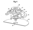
Figur 4 die Montage des Modulträgers mit dem Befestigungsclip in einer Öffnung im Türblech mittels Rastelementen; -
Figur 5 eine schematische Ansicht des vormontierten Modulträgers im Türblech; -
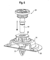
Figur 6 die Montage der Türverkleidung (nicht dargestellt) mit vormontiertem Befestigungselement (Pin) in den Modulträger; -
Figur 7 die Zentrierung des stiftförmigen Befestigungselements im Modulträger über die Aufnahme im Kopfteil des Befestigungsclips mit einer Fase; -
Figur 8 den Sitz des stiftförmigen Befestigungselements für die Türverkleidung im Modulträger und Türblech in einer schematischen Darstellung; -
Figur 9 eine Schnittansicht zur Funktionsbeschreibung einzelner Bestandteile der erfindungsgemäßen Befestigungsvorrichtung. - Wie in den beigefügten Zeichnungen,
Figuren 1 bis 9 , anhand einer bevorzugten Ausführungsform gezeigt ist, weist die erfindungsgemäße Befestigungsvorrichtung einen Befestigungsclip 12 und ein Modulträgerteil 14 auf. Im Modulträgerteil 14 ist eine Öffnung 16 zur Aufnahme des Befestigungsclips 12 vorgesehen. Der Befestigungsclip 12 weist einen Schaft 18 und ein an den Schaft angeformtes Kopfteil 20 auf. Unterhalb des Kopfteils 20 sind am Schaft 18 Verriegelungselemente 22 vorgesehen, die in die Öffnung 16 des Modulträgerteils 14 eingreifen und den Befestigungsclip 12 an dem Modulträgerteil 14 festlegen (Figuren 1 bis 3 ). - Die Verriegelungselemente 22 sind vorzugsweise durch einen oder mehrere radial vom Schaft 18 vorstehende Vorsprünge gebildet. Das Kopfteil 20 des Befestigungsclips 12 kann ferner ein scheibenförmiges Element 24 mit einer umlaufenden Dichtung 26 aufweisen. Im montierten Zustand wird die Öffnung 16 des Modulträgers 14 mit dem scheibenförmigen Element und der umlaufenden Dichtung 26 abgedichtet.
- Im Kopfteil 20 ist eine Aufnahme 28 für ein mit dem Bezugszeichen 30 bezeichnetes Befestigungselement eines Verkleidungsteils (nicht dargestellt) gebildet. Darüber hinaus weist das Kopfteil einen Antriebsabschnitt 32 mit einem Außenkant auf, der in der gezeigten Ausführungsform als Achtkant ausgestaltet ist. Über den Antriebsabschnitt kann der in das Modulträgerteil 14 eingebrachte Befestigungsclip 12 verdreht und am Modulträgerteil 14 verriegelt werden. An der Unterseite des Modulträgerteils 14 ist vorzugsweise ein Anschlag 34 gebildet, der die Verdrehung der Verriegelungselemente 22 begrenzt und die Position des Befestigungsclips 12 im Modulträgerteil 14 definiert.
- Wie in
Figur 4 dargestellt, wird der Befestigungsclip 12 mit dem Modulträgerteil 14 als vormontierte Einheit in die Bohrung 36 eines Türblechs 38 eingesetzt. Über Rastelemente 40 am Schaft 18 wird der Modulträger 14 mit dem Befestigungsclip 12 in der Bohrung 36 des Türblechs 38 gehalten. Der Modulträger 14 weist einen Flansch 42 auf, mit dem er im montierten Zustand dicht am Türblech 38 anliegt. - Das Befestigungselement 30 des Verkleidungsteils umfaßt einen stiftförmigen Abschnitt 44, mit dem es in die Aufnahme 28 im Kopfteil 20 des Befestigungsclips 12 eingreift. Über eine Fase 46 in der Aufnahme 28 erfolgt eine Zentrierung des Befestigungselements 30.
- Der stiftförmige Abschnitt 44 des Befestigungselements weist ferner einen Rastring 48 auf, mit dem der stiftförmige Abschnitt 44 in der Aufnahme 28 im Kopfteil festgelegt ist. Der Rastring kann zusätzlich mit einer Dichtlippe 50 versehen sein, die den stiftförmigen Abschnitt 44 gegen die Aufnahme 28 im Kopfteil 12 abdichtet. Des weiteren kann der stiftförmige Abschnitt 44 einen Dichtring 52 in Form eines O-Rings aufweisen, der im montierten Zustand den stiftförmigen Abschnitt 44 zur Öffnung 16 im Modulträger abdichtet.
- Schließlich kann das Befestigungselement 30 ein Kopfteil mit Toleranzausgleichsmitteln 58 zum Einlegevorbau der Türverkleidung hin aufweisen, die in
Fig. 9 mit dem Bezugszeichen 58 versehen sind. - In
Figur 9 ist mit dem Bezugszeichen 32 der Antriebsabschnitt des Kopfteils 20 bezeichnet. Der Antriebsabschnitt 32 ist als Achtkant ausgebildet und dient der Montage des Befestigungsclips 12 in dem Modulträgerteil 14. Ein Anschlag im Befestigungsclip 12 ist mit dem Bezugszeichen 54 versehen. - Die Verrastung des Befestigungselementes 30 im Befestigungsclip 12 ist mit dem Bezugszeichen 56 versehen. Die erwartete Auszugskraft nach der Verrastung des Befestigungselementes 30 beträgt etwa 130 N.
- Die Dichtung am Befestigungselement 30, die im montierten Zustand das Befestigungselement 30 zum Befestigungsclip 12 abdichtet, ist mit dem Bezugszeichen 52 versehen.
- In
Figur 9 ist ferner die umlaufende Dichtung 26 des Befestigungsclips 12 gezeigt. Die Dichtung 26 dichtet im montierten Zustand den Befestigungsclip 12 zum Modulträgerteil 14 ab. - Mit dem Bezugszeichen 60 ist die Sicherung der Rastelemente 40 durch das Befestigungselement 30 in der Endmontagestellung bezeichnet. Die erwartete Auszugskraft des Befestigungsclips 12 aus dem Türblech 38 ist größer als 250 N. Die Auszugskraft des Befestigungselementes 30 aus dem Befestigungsclip 12 sollte geringer sein, als die Auszugskraft des Befestigungsclips 12 aus dem Türblech 38.
Claims (17)
- Befestigungsvorrichtung, insbesondere zur Befestigung eines Modulträgers und eines Verkleidungsteils an einem Rohbauteil eines Kraftfahrzeugs, mit
einem Befestigungsclip und einem Modulträgerteil mit einer Öffnung zur Aufnahme des Befestigungsclips, wobei der Befestigungsclip einen Schaft und ein an den Schaft angeformtes Kopfteil aufweist und wobei Verriegelungselemente am Schaft unterhalb des Kopfteils vorgesehen sind, die in die Öffnung des Modulträgerteils eingreifen und den Befestigungsclip an dem Modulträgerteil festlegen. - Befestigungsvorrichtung nach Anspruch 1, dadurch gekennzeichnet, daß der Schaft ein oder mehrere Rastelemente zur Aufnahme in der Bohrung eines Rohbauteils aufweist.
- Befestigungsvorrichtung nach Anspruch 1 oder 2, dadurch gekennzeichnet, daß die Verriegelungselemente durch einen oder mehrere radial vom Schaft vorstehende Vorsprünge gebildet sind.
- Befestigungsvorrichtung nach einem der vorhergehenden Ansprüche, dadurch gekennzeichnet, daß das Kopfteil ein scheibenförmiges Element mit einer umlaufenden Dichtung zur Abdichtung der Öffnung im Kopfteil aufweist.
- Befestigungsvorrichtung nach einem der vorhergehenden Ansprüche, dadurch gekennzeichnet, daß das Kopfteil eine Aufnahme für ein Befestigungselement eines Verkleidungsteils aufweist.
- Befestigungsvorrichtung nach einem der vorhergehenden Ansprüche, dadurch gekennzeichnet, daß das Kopfteil einen Antriebsabschnitt mit einem Außenkant aufweist.
- Befestigungsvorrichtung nach einem der vorhergehenden Ansprüche, dadurch gekennzeichnet, daß das Modulträgerteil einen Anschlag für die Verriegelungselemente aufweist.
- Befestigungsvorrichtung nach einem der vorhergehenden Ansprüche, dadurch gekennzeichnet, daß das Modulträgerteil einen Flansch zur dichten Anlage an dem Rohbauteil aufweist.
- Befestigungsvorrichtung nach einem der vorhergehenden Ansprüche, dadurch gekennzeichnet, daß die Öffnung im Modulträgerteil mit der Form der Verriegelungselemente korrespondiert.
- Befestigungsvorrichtung nach einem der vorhergehenden Ansprüche, dadurch gekennzeichnet, daß der Befestigungsclip und das Modulträgerteil eine vormontierte Einheit bilden.
- Befestigungsvorrichtung nach einem der vorhergehenden Ansprüche 5 bis 10, dadurch gekennzeichnet, daß das Befestigungselement für das Verkleidungsteil einen stiftförmigen Abschnitt aufweist, der in die Aufnahme des Kopfteils eingreift.
- Befestigungsvorrichtung nach Anspruch 11, dadurch gekennzeichnet, daß der Schaft einen mit der Aufnahme im Kopfteil korrespondierenden Hohlraum aufweist und der stiftförmige Abschnitt des Befestigungselementes in den Hohlraum eingreift.
- Befestigungsvorrichtung nach einem der Ansprüche 11 oder 12, dadurch gekennzeichnet, daß der stiftförmige Abschnitt einen Rastring aufweist, mit dem der stiftförmige Abschnitt in der Aufnahme im Kopfteil festgelegt ist.
- Befestigungsvorrichtung nach einem der Ansprüche 11 bis 13, dadurch gekennzeichnet, daß der stiftförmige Abschnitt eine Dichtung aufweist, die den stiftförmigen Abschnitt zur Öffnung im Modulträger abdichtet.
- Befestigungsvorrichtung nach einem der Ansprüche 13 oder 14, dadurch gekennzeichnet, daß der Rastring eine Dichtlippe aufweist, die den stiftförmigen Abschnitt gegen die Aufnahme im Kopfteil abdichtet.
- Befestigungsvorrichtung nach einem der Ansprüche 5 bis 15, dadurch gekennzeichnet, daß der Befestigungsclip und das Modulträgerteil aus Kunststoff gebildet sind.
- Befestigungsvorrichtung nach einem der vorhergehenden Ansprüche, dadurch gekennzeichnet, daß das Befestigungselement für das Verkleidungsteil ein Kopfteil mit Toleranzausgleichsmitteln aufweist.
Applications Claiming Priority (1)
| Application Number | Priority Date | Filing Date | Title |
|---|---|---|---|
| DE202007002595U DE202007002595U1 (de) | 2007-02-22 | 2007-02-22 | Befestigungsvorrichtung |
Publications (3)
| Publication Number | Publication Date |
|---|---|
| EP1961616A2 true EP1961616A2 (de) | 2008-08-27 |
| EP1961616A3 EP1961616A3 (de) | 2009-01-07 |
| EP1961616B1 EP1961616B1 (de) | 2013-04-10 |
Family
ID=38460708
Family Applications (1)
| Application Number | Title | Priority Date | Filing Date |
|---|---|---|---|
| EP08001204.0A Not-in-force EP1961616B1 (de) | 2007-02-22 | 2008-01-23 | Befestigungsvorrichtung |
Country Status (7)
| Country | Link |
|---|---|
| US (1) | US20080201920A1 (de) |
| EP (1) | EP1961616B1 (de) |
| JP (1) | JP5280693B2 (de) |
| KR (1) | KR101470629B1 (de) |
| CN (1) | CN101251142B (de) |
| DE (1) | DE202007002595U1 (de) |
| ES (1) | ES2405656T3 (de) |
Families Citing this family (33)
| Publication number | Priority date | Publication date | Assignee | Title |
|---|---|---|---|---|
| US7748089B2 (en) * | 2008-01-15 | 2010-07-06 | Illinois Tool Works Inc. | Auger clip assembly |
| JP5061989B2 (ja) * | 2008-03-26 | 2012-10-31 | アイシン精機株式会社 | フレームガーニッシュの取付構造 |
| DE202008006958U1 (de) * | 2008-05-23 | 2008-10-02 | Trw Automotive Electronics & Components Gmbh | Verbindungsbaugruppe zur Befestigung eines Anbauelements auf einem Träger |
| JP5209534B2 (ja) * | 2009-02-23 | 2013-06-12 | アイシン精機株式会社 | フレームガーニッシュ取付構造 |
| EP2450582A4 (de) * | 2009-06-29 | 2014-01-08 | Nifco Inc | Klemme und klemmvorrichtung |
| DE102009042845B4 (de) * | 2009-09-24 | 2019-02-14 | Dr. Ing. H.C. F. Porsche Aktiengesellschaft | Halteclip |
| KR101023443B1 (ko) * | 2009-09-30 | 2011-03-25 | 대기오토모티브 주식회사 | 자동차용 잠금장치 |
| DE102009050085A1 (de) * | 2009-10-20 | 2011-04-21 | Johnson Controls Interiors Gmbh & Co. Kg | Befestigungsvorrichtung für ein Innenausstattungsteil an der Karosserie eines Kraftfahrzeuges |
| JP2011134541A (ja) * | 2009-12-24 | 2011-07-07 | Nifco Inc | 連結構造 |
| DE102010007041A1 (de) * | 2010-02-05 | 2011-08-11 | Audi Ag, 85057 | Befestigungssystem für flächige Innenverkleidungsteile eines Kraftfahrzeugs |
| DE102010020961A1 (de) * | 2010-04-30 | 2011-11-03 | Continental Automotive Gmbh | Verfahren und Befestigungsvorrichtung zur Befestigung einer Baugruppe in einer Öffnung einer Wand eines Fahrzeugs |
| DE102010024227B4 (de) * | 2010-06-18 | 2021-03-04 | Audi Ag | Montagevorrichtung und Verfahren zur Montage eines Bauteils an einem Trägerteil einer Fahrzeugkarosserie |
| DE102010030964A1 (de) | 2010-07-06 | 2012-01-12 | Bayerische Motoren Werke Aktiengesellschaft | Befestigungsanordnung zum Befestigen von Kraftfahrzeugbauteilen |
| DE202010008192U1 (de) * | 2010-07-30 | 2010-10-07 | Newfrey Llc, Newark | Befestigungselement und Befestigungsanordnung mit einem Befestigungselement |
| US9119327B2 (en) * | 2010-10-26 | 2015-08-25 | Tdk-Lambda Corporation | Thermal management system and method |
| FR2990165B1 (fr) * | 2012-05-04 | 2014-05-09 | Trw Automotive Electron & Comp | Clip de fixation |
| RU2605116C2 (ru) * | 2012-08-13 | 2016-12-20 | Бриджстоун Корпорейшн | Способ замены компонента оборудования пресс-формы для вулканизации шины |
| JP6054192B2 (ja) * | 2013-01-31 | 2016-12-27 | 大和化成工業株式会社 | クリップの装着構造 |
| DE102014224929A1 (de) * | 2014-12-04 | 2016-06-09 | Bayerische Motoren Werke Aktiengesellschaft | Clipwave System |
| JP6106655B2 (ja) * | 2014-12-05 | 2017-04-05 | 本田技研工業株式会社 | ロック装置 |
| US10024075B2 (en) * | 2015-04-23 | 2018-07-17 | Newpark Mats & Integrated Services Llc | Apparatus, system and methods for supporting one or more upright items from a support surface |
| EP3142207B1 (de) * | 2015-09-11 | 2018-06-06 | NKT HV Cables GmbH | Befestigungsvorrichtung für einen kabelabschluss und anordnung mit der befestigungsvorrichtung und dem kabelabschluss |
| DE102016107357A1 (de) | 2016-04-20 | 2017-10-26 | Witte Automotive Gmbh | Vorrichtung zum Ausgleichen von Toleranzen |
| DE202016104408U1 (de) * | 2016-08-10 | 2017-11-13 | Böllhoff Verbindungstechnik GmbH | Befestigungsclip |
| US10124742B2 (en) * | 2017-03-13 | 2018-11-13 | Honda Patents & Technologies North America, Llc. | Fastener apparatus, and methods of use and manufacture thereof |
| US11345220B2 (en) | 2018-02-26 | 2022-05-31 | Magna Closures Inc. | Isolated fixing system for actuators |
| FR3084118B1 (fr) * | 2018-07-19 | 2020-11-27 | A Raymond Et Cie | Dispositif de fixation de deux elements plans |
| DE102018214627A1 (de) * | 2018-08-29 | 2020-03-05 | Ford Global Technologies, Llc | Fahrzeugtür |
| US11511610B2 (en) | 2018-11-12 | 2022-11-29 | Shape Corp. | Vehicle door carrier with integrated edge seal and method of manufacture |
| DE102019110701A1 (de) * | 2019-04-25 | 2020-10-29 | Bayerische Motoren Werke Aktiengesellschaft | Halteelement zum halten eines zu befestigenden bauteils und haltesystem mit einem solchen |
| KR102273864B1 (ko) * | 2019-08-01 | 2021-07-06 | 주식회사 광진 | 자동차 도어용 결합장치 |
| DE102020204179A1 (de) | 2020-03-31 | 2021-09-30 | Witte Automotive Gmbh | Befestigungselement |
| CN114179731A (zh) * | 2022-01-19 | 2022-03-15 | 华晨鑫源重庆汽车有限公司 | 一种用于将内饰板固定在车身钣金上的卡扣 |
Citations (1)
| Publication number | Priority date | Publication date | Assignee | Title |
|---|---|---|---|---|
| DE19753678A1 (de) | 1997-12-03 | 1999-06-10 | United Carr Gmbh Trw | Verbindung zwischen einem Träger, insbesondere einem Karosserieteil eines Kraftfahrzeuges, und einem Plattenelement, insbesondere einer Türverkleidung |
Family Cites Families (15)
| Publication number | Priority date | Publication date | Assignee | Title |
|---|---|---|---|---|
| US3107454A (en) * | 1960-08-17 | 1963-10-22 | Anaconda American Brass Co | Sheet metal roofing |
| GB1136662A (en) * | 1966-04-23 | 1968-12-11 | Gkn Screws Fasteners Ltd | Improvements in or relating to quick release fasteners |
| US4732519A (en) * | 1986-12-24 | 1988-03-22 | Illinois Tool Works Inc. | Fastener assembly with axial play |
| JPH0743471Y2 (ja) * | 1990-02-28 | 1995-10-09 | 株式会社ニフコ | クリツプ |
| FR2670253B1 (fr) * | 1990-12-10 | 1993-07-16 | Itw De France | Ecrou en matiere plastique. |
| DE19806827A1 (de) * | 1998-02-18 | 1999-08-19 | Trw Automotive Electron & Comp | Verbindung zwischen einem Träger und einem Plattenelement |
| JP3749017B2 (ja) * | 1998-04-03 | 2006-02-22 | 株式会社パイオラックス | 固定クリップ |
| JP4630438B2 (ja) * | 2000-09-27 | 2011-02-09 | 株式会社ニフコ | クリップ |
| DE20017376U1 (de) * | 2000-10-10 | 2001-02-15 | Trw Automotive Electron & Comp | Vorrichtung zur Verbindung eines Trägers, insbesondere eines Karosserieteils eines Kraftfahrzeuges, mit einem Plattenelement, insbesondere einer Tür- oder Wandverkleidung |
| US6594870B1 (en) * | 2001-01-22 | 2003-07-22 | Johnson Controls Technology Company | Panel fastener |
| JP2004028244A (ja) * | 2002-06-27 | 2004-01-29 | Nippon Pop Rivets & Fasteners Ltd | クリップ及び部材連結装置 |
| JP2004116722A (ja) * | 2002-09-27 | 2004-04-15 | Nippon Pop Rivets & Fasteners Ltd | クリップ |
| JP4152829B2 (ja) * | 2003-07-31 | 2008-09-17 | ポップリベット・ファスナー株式会社 | カーテンシールドエアバッグ用クリップ |
| US20050220568A1 (en) * | 2004-03-31 | 2005-10-06 | Tokyo Electron Limited | Method and system for fastening components used in plasma processing |
| US7152281B2 (en) * | 2005-04-28 | 2006-12-26 | Illinois Tool Works Inc | Fastener and fastened assembly |
-
2007
- 2007-02-22 DE DE202007002595U patent/DE202007002595U1/de not_active Expired - Lifetime
-
2008
- 2008-01-23 ES ES08001204T patent/ES2405656T3/es active Active
- 2008-01-23 EP EP08001204.0A patent/EP1961616B1/de not_active Not-in-force
- 2008-01-30 JP JP2008018514A patent/JP5280693B2/ja not_active Expired - Fee Related
- 2008-02-20 US US12/070,612 patent/US20080201920A1/en not_active Abandoned
- 2008-02-21 KR KR1020080015821A patent/KR101470629B1/ko active IP Right Grant
- 2008-02-21 CN CN2008100814362A patent/CN101251142B/zh not_active Expired - Fee Related
Patent Citations (1)
| Publication number | Priority date | Publication date | Assignee | Title |
|---|---|---|---|---|
| DE19753678A1 (de) | 1997-12-03 | 1999-06-10 | United Carr Gmbh Trw | Verbindung zwischen einem Träger, insbesondere einem Karosserieteil eines Kraftfahrzeuges, und einem Plattenelement, insbesondere einer Türverkleidung |
Also Published As
| Publication number | Publication date |
|---|---|
| KR101470629B1 (ko) | 2014-12-08 |
| EP1961616A3 (de) | 2009-01-07 |
| DE202007002595U1 (de) | 2007-08-30 |
| CN101251142A (zh) | 2008-08-27 |
| ES2405656T3 (es) | 2013-05-31 |
| KR20080078575A (ko) | 2008-08-27 |
| US20080201920A1 (en) | 2008-08-28 |
| JP5280693B2 (ja) | 2013-09-04 |
| CN101251142B (zh) | 2011-05-18 |
| EP1961616B1 (de) | 2013-04-10 |
| JP2008202786A (ja) | 2008-09-04 |
Similar Documents
| Publication | Publication Date | Title |
|---|---|---|
| EP1961616B1 (de) | Befestigungsvorrichtung | |
| DE102005028870B4 (de) | Tüllen- und Verankerungsstruktur | |
| EP2463134A1 (de) | Dichtungsvorrichtung für eine Scheibeneinheit und dazugehöriges Herstellungsverfahren | |
| WO2021008728A1 (de) | Dachanbindungssystem und verfahren | |
| EP2305519A1 (de) | Montagesystem für die Befestigung einer Stoßfängerverkleidung | |
| DE202008012698U1 (de) | Befestigungsvorrichtung | |
| DE102015006838A1 (de) | Kraftfahrzeug | |
| DE102005055934A1 (de) | Trägerelement zur elastischen Verbindung zweier Bauteile sowie Verfahren zur Bereitstellung eines Trägerelementes | |
| EP3638524B1 (de) | Dichtungsanordnung zur führung und abdichtung einer vertikal bewegbaren fahrzeugfensterscheibe | |
| DE102019104398A1 (de) | Isoliertes Befestigungssystem für Stellglieder | |
| EP3334947B1 (de) | Anordnung und verfahren zur sicherung eines befestigungselementes | |
| DE202005013298U1 (de) | Kunststoffformteil, insbesondere für Kraftfahrzeuge, zur flüssigkeitsdichten Abdeckung einer fensterartigen Öffnung | |
| DE102004050674B4 (de) | Befestigungsanordnung für elektrische Komponenten in einem Fahrzeug | |
| DE102017100776B3 (de) | Verfahren zur Herstellung einer Scheibeneinheit sowie Scheibeneinheit | |
| DE202013101020U1 (de) | Vorrichtung zum Befestigen eines Trägerelements an der Karosseriestruktur eines Kraftfahrzeugs | |
| EP2305518A1 (de) | Vorrichtung für die Befestigung einer Stoßfängerverkleidung | |
| DE102009045338B4 (de) | Scheibenwischvorrichtung | |
| DE102016209731A1 (de) | Halbintegrierte Abdeckung für ein freiliegendes Befestigungselement | |
| DE102011051429A1 (de) | Befestigungseinrichtung | |
| EP1972424B1 (de) | Verbindung zweier Funktionselemente, nämlich einer Scheibe mit einem Verdeckelement und Verfahren zur Festlegung einer Scheibe an einem Verdeckelement | |
| DE202008006499U1 (de) | Trägerelement zum Einbau in ein Kraftfahrzeug | |
| DE10211660B4 (de) | Lösbare Abdeckung für eine Montageöffnung in einer Türinnenverkleidung eines Fahrzeugs | |
| DE19739555C2 (de) | Dichtungsanordnung für eine Tür eines Kraftfahrzeuges | |
| WO2022002747A1 (de) | Türbaugruppe einer fahrzeugtür | |
| EP3829908B1 (de) | Türbaugruppe mit befestigungselement und montageverfahren |
Legal Events
| Date | Code | Title | Description |
|---|---|---|---|
| PUAI | Public reference made under article 153(3) epc to a published international application that has entered the european phase |
Free format text: ORIGINAL CODE: 0009012 |
|
| AK | Designated contracting states |
Kind code of ref document: A2 Designated state(s): AT BE BG CH CY CZ DE DK EE ES FI FR GB GR HR HU IE IS IT LI LT LU LV MC MT NL NO PL PT RO SE SI SK TR |
|
| AX | Request for extension of the european patent |
Extension state: AL BA MK RS |
|
| RIN1 | Information on inventor provided before grant (corrected) |
Inventor name: JATZKE, STEFAN Inventor name: LOEWE, HUBERT Inventor name: HOFMANN, JUERGEN |
|
| PUAL | Search report despatched |
Free format text: ORIGINAL CODE: 0009013 |
|
| AK | Designated contracting states |
Kind code of ref document: A3 Designated state(s): AT BE BG CH CY CZ DE DK EE ES FI FR GB GR HR HU IE IS IT LI LT LU LV MC MT NL NO PL PT RO SE SI SK TR |
|
| AX | Request for extension of the european patent |
Extension state: AL BA MK RS |
|
| 17P | Request for examination filed |
Effective date: 20090630 |
|
| AKX | Designation fees paid |
Designated state(s): AT BE BG CH CY CZ DE DK EE ES FI FR GB GR HR HU IE IS IT LI LT LU LV MC MT NL NO PL PT RO SE SI SK TR |
|
| 17Q | First examination report despatched |
Effective date: 20090819 |
|
| REG | Reference to a national code |
Ref country code: DE Ref legal event code: R079 Ref document number: 502008009657 Country of ref document: DE Free format text: PREVIOUS MAIN CLASS: B60R0011000000 Ipc: B60R0013020000 |
|
| GRAP | Despatch of communication of intention to grant a patent |
Free format text: ORIGINAL CODE: EPIDOSNIGR1 |
|
| RIC1 | Information provided on ipc code assigned before grant |
Ipc: F16B 21/09 20060101ALI20121010BHEP Ipc: B60R 11/00 20060101ALI20121010BHEP Ipc: F16B 5/06 20060101ALI20121010BHEP Ipc: F16B 21/02 20060101ALI20121010BHEP Ipc: F16B 19/10 20060101ALI20121010BHEP Ipc: B60R 11/02 20060101ALI20121010BHEP Ipc: B60R 13/06 20060101ALI20121010BHEP Ipc: B60R 13/02 20060101AFI20121010BHEP |
|
| GRAS | Grant fee paid |
Free format text: ORIGINAL CODE: EPIDOSNIGR3 |
|
| GRAA | (expected) grant |
Free format text: ORIGINAL CODE: 0009210 |
|
| AK | Designated contracting states |
Kind code of ref document: B1 Designated state(s): AT BE BG CH CY CZ DE DK EE ES FI FR GB GR HR HU IE IS IT LI LT LU LV MC MT NL NO PL PT RO SE SI SK TR |
|
| REG | Reference to a national code |
Ref country code: GB Ref legal event code: FG4D Free format text: NOT ENGLISH |
|
| REG | Reference to a national code |
Ref country code: AT Ref legal event code: REF Ref document number: 605790 Country of ref document: AT Kind code of ref document: T Effective date: 20130415 Ref country code: CH Ref legal event code: EP |
|
| REG | Reference to a national code |
Ref country code: IE Ref legal event code: FG4D Free format text: LANGUAGE OF EP DOCUMENT: GERMAN |
|
| REG | Reference to a national code |
Ref country code: ES Ref legal event code: FG2A Ref document number: 2405656 Country of ref document: ES Kind code of ref document: T3 Effective date: 20130531 |
|
| REG | Reference to a national code |
Ref country code: DE Ref legal event code: R096 Ref document number: 502008009657 Country of ref document: DE Effective date: 20130606 |
|
| PG25 | Lapsed in a contracting state [announced via postgrant information from national office to epo] |
Ref country code: SI Free format text: LAPSE BECAUSE OF FAILURE TO SUBMIT A TRANSLATION OF THE DESCRIPTION OR TO PAY THE FEE WITHIN THE PRESCRIBED TIME-LIMIT Effective date: 20130410 |
|
| REG | Reference to a national code |
Ref country code: LT Ref legal event code: MG4D Ref country code: NL Ref legal event code: VDEP Effective date: 20130410 |
|
| PG25 | Lapsed in a contracting state [announced via postgrant information from national office to epo] |
Ref country code: SE Free format text: LAPSE BECAUSE OF FAILURE TO SUBMIT A TRANSLATION OF THE DESCRIPTION OR TO PAY THE FEE WITHIN THE PRESCRIBED TIME-LIMIT Effective date: 20130410 Ref country code: PT Free format text: LAPSE BECAUSE OF FAILURE TO SUBMIT A TRANSLATION OF THE DESCRIPTION OR TO PAY THE FEE WITHIN THE PRESCRIBED TIME-LIMIT Effective date: 20130812 Ref country code: IS Free format text: LAPSE BECAUSE OF FAILURE TO SUBMIT A TRANSLATION OF THE DESCRIPTION OR TO PAY THE FEE WITHIN THE PRESCRIBED TIME-LIMIT Effective date: 20130810 Ref country code: LT Free format text: LAPSE BECAUSE OF FAILURE TO SUBMIT A TRANSLATION OF THE DESCRIPTION OR TO PAY THE FEE WITHIN THE PRESCRIBED TIME-LIMIT Effective date: 20130410 Ref country code: GR Free format text: LAPSE BECAUSE OF FAILURE TO SUBMIT A TRANSLATION OF THE DESCRIPTION OR TO PAY THE FEE WITHIN THE PRESCRIBED TIME-LIMIT Effective date: 20130711 Ref country code: NL Free format text: LAPSE BECAUSE OF FAILURE TO SUBMIT A TRANSLATION OF THE DESCRIPTION OR TO PAY THE FEE WITHIN THE PRESCRIBED TIME-LIMIT Effective date: 20130410 Ref country code: NO Free format text: LAPSE BECAUSE OF FAILURE TO SUBMIT A TRANSLATION OF THE DESCRIPTION OR TO PAY THE FEE WITHIN THE PRESCRIBED TIME-LIMIT Effective date: 20130710 Ref country code: FI Free format text: LAPSE BECAUSE OF FAILURE TO SUBMIT A TRANSLATION OF THE DESCRIPTION OR TO PAY THE FEE WITHIN THE PRESCRIBED TIME-LIMIT Effective date: 20130410 |
|
| PG25 | Lapsed in a contracting state [announced via postgrant information from national office to epo] |
Ref country code: HR Free format text: LAPSE BECAUSE OF FAILURE TO SUBMIT A TRANSLATION OF THE DESCRIPTION OR TO PAY THE FEE WITHIN THE PRESCRIBED TIME-LIMIT Effective date: 20130410 Ref country code: CY Free format text: LAPSE BECAUSE OF FAILURE TO SUBMIT A TRANSLATION OF THE DESCRIPTION OR TO PAY THE FEE WITHIN THE PRESCRIBED TIME-LIMIT Effective date: 20130410 Ref country code: LV Free format text: LAPSE BECAUSE OF FAILURE TO SUBMIT A TRANSLATION OF THE DESCRIPTION OR TO PAY THE FEE WITHIN THE PRESCRIBED TIME-LIMIT Effective date: 20130410 Ref country code: PL Free format text: LAPSE BECAUSE OF FAILURE TO SUBMIT A TRANSLATION OF THE DESCRIPTION OR TO PAY THE FEE WITHIN THE PRESCRIBED TIME-LIMIT Effective date: 20130410 Ref country code: BG Free format text: LAPSE BECAUSE OF FAILURE TO SUBMIT A TRANSLATION OF THE DESCRIPTION OR TO PAY THE FEE WITHIN THE PRESCRIBED TIME-LIMIT Effective date: 20130710 |
|
| PG25 | Lapsed in a contracting state [announced via postgrant information from national office to epo] |
Ref country code: DK Free format text: LAPSE BECAUSE OF FAILURE TO SUBMIT A TRANSLATION OF THE DESCRIPTION OR TO PAY THE FEE WITHIN THE PRESCRIBED TIME-LIMIT Effective date: 20130410 Ref country code: SK Free format text: LAPSE BECAUSE OF FAILURE TO SUBMIT A TRANSLATION OF THE DESCRIPTION OR TO PAY THE FEE WITHIN THE PRESCRIBED TIME-LIMIT Effective date: 20130410 Ref country code: CZ Free format text: LAPSE BECAUSE OF FAILURE TO SUBMIT A TRANSLATION OF THE DESCRIPTION OR TO PAY THE FEE WITHIN THE PRESCRIBED TIME-LIMIT Effective date: 20130410 Ref country code: EE Free format text: LAPSE BECAUSE OF FAILURE TO SUBMIT A TRANSLATION OF THE DESCRIPTION OR TO PAY THE FEE WITHIN THE PRESCRIBED TIME-LIMIT Effective date: 20130410 |
|
| PLBE | No opposition filed within time limit |
Free format text: ORIGINAL CODE: 0009261 |
|
| STAA | Information on the status of an ep patent application or granted ep patent |
Free format text: STATUS: NO OPPOSITION FILED WITHIN TIME LIMIT |
|
| PG25 | Lapsed in a contracting state [announced via postgrant information from national office to epo] |
Ref country code: RO Free format text: LAPSE BECAUSE OF FAILURE TO SUBMIT A TRANSLATION OF THE DESCRIPTION OR TO PAY THE FEE WITHIN THE PRESCRIBED TIME-LIMIT Effective date: 20130410 |
|
| 26N | No opposition filed |
Effective date: 20140113 |
|
| REG | Reference to a national code |
Ref country code: DE Ref legal event code: R097 Ref document number: 502008009657 Country of ref document: DE Effective date: 20140113 |
|
| BERE | Be: lapsed |
Owner name: TRW AUTOMOTIVE ELECTRONICS & COMPONENTS G.M.B.H. Effective date: 20140131 |
|
| PG25 | Lapsed in a contracting state [announced via postgrant information from national office to epo] |
Ref country code: LU Free format text: LAPSE BECAUSE OF FAILURE TO SUBMIT A TRANSLATION OF THE DESCRIPTION OR TO PAY THE FEE WITHIN THE PRESCRIBED TIME-LIMIT Effective date: 20140123 Ref country code: MC Free format text: LAPSE BECAUSE OF FAILURE TO SUBMIT A TRANSLATION OF THE DESCRIPTION OR TO PAY THE FEE WITHIN THE PRESCRIBED TIME-LIMIT Effective date: 20130410 |
|
| REG | Reference to a national code |
Ref country code: CH Ref legal event code: PL |
|
| PG25 | Lapsed in a contracting state [announced via postgrant information from national office to epo] |
Ref country code: CH Free format text: LAPSE BECAUSE OF NON-PAYMENT OF DUE FEES Effective date: 20140131 Ref country code: LI Free format text: LAPSE BECAUSE OF NON-PAYMENT OF DUE FEES Effective date: 20140131 |
|
| REG | Reference to a national code |
Ref country code: IE Ref legal event code: MM4A |
|
| REG | Reference to a national code |
Ref country code: FR Ref legal event code: PLFP Year of fee payment: 8 |
|
| PG25 | Lapsed in a contracting state [announced via postgrant information from national office to epo] |
Ref country code: IE Free format text: LAPSE BECAUSE OF NON-PAYMENT OF DUE FEES Effective date: 20140123 Ref country code: BE Free format text: LAPSE BECAUSE OF NON-PAYMENT OF DUE FEES Effective date: 20140131 |
|
| REG | Reference to a national code |
Ref country code: AT Ref legal event code: MM01 Ref document number: 605790 Country of ref document: AT Kind code of ref document: T Effective date: 20140123 |
|
| PG25 | Lapsed in a contracting state [announced via postgrant information from national office to epo] |
Ref country code: AT Free format text: LAPSE BECAUSE OF NON-PAYMENT OF DUE FEES Effective date: 20140123 |
|
| REG | Reference to a national code |
Ref country code: FR Ref legal event code: PLFP Year of fee payment: 9 |
|
| PG25 | Lapsed in a contracting state [announced via postgrant information from national office to epo] |
Ref country code: MT Free format text: LAPSE BECAUSE OF FAILURE TO SUBMIT A TRANSLATION OF THE DESCRIPTION OR TO PAY THE FEE WITHIN THE PRESCRIBED TIME-LIMIT Effective date: 20130410 |
|
| PG25 | Lapsed in a contracting state [announced via postgrant information from national office to epo] |
Ref country code: HU Free format text: LAPSE BECAUSE OF FAILURE TO SUBMIT A TRANSLATION OF THE DESCRIPTION OR TO PAY THE FEE WITHIN THE PRESCRIBED TIME-LIMIT; INVALID AB INITIO Effective date: 20080123 Ref country code: TR Free format text: LAPSE BECAUSE OF FAILURE TO SUBMIT A TRANSLATION OF THE DESCRIPTION OR TO PAY THE FEE WITHIN THE PRESCRIBED TIME-LIMIT Effective date: 20130410 |
|
| REG | Reference to a national code |
Ref country code: GB Ref legal event code: 732E Free format text: REGISTERED BETWEEN 20160915 AND 20160921 |
|
| REG | Reference to a national code |
Ref country code: DE Ref legal event code: R082 Ref document number: 502008009657 Country of ref document: DE Representative=s name: MEISSNER BOLTE PATENTANWAELTE RECHTSANWAELTE P, DE Ref country code: DE Ref legal event code: R082 Ref document number: 502008009657 Country of ref document: DE Representative=s name: HGF EUROPE LLP, DE Ref country code: DE Ref legal event code: R082 Ref document number: 502008009657 Country of ref document: DE Representative=s name: HAUCK PATENTANWALTSPARTNERSCHAFT MBB, DE |
|
| REG | Reference to a national code |
Ref country code: FR Ref legal event code: PLFP Year of fee payment: 10 |
|
| PGFP | Annual fee paid to national office [announced via postgrant information from national office to epo] |
Ref country code: FR Payment date: 20170125 Year of fee payment: 10 |
|
| PGFP | Annual fee paid to national office [announced via postgrant information from national office to epo] |
Ref country code: GB Payment date: 20170127 Year of fee payment: 10 |
|
| PGFP | Annual fee paid to national office [announced via postgrant information from national office to epo] |
Ref country code: ES Payment date: 20170126 Year of fee payment: 10 Ref country code: IT Payment date: 20170124 Year of fee payment: 10 |
|
| REG | Reference to a national code |
Ref country code: DE Ref legal event code: R082 Ref document number: 502008009657 Country of ref document: DE Representative=s name: MEISSNER BOLTE PATENTANWAELTE RECHTSANWAELTE P, DE Ref country code: DE Ref legal event code: R082 Ref document number: 502008009657 Country of ref document: DE Representative=s name: HGF EUROPE LLP, DE Ref country code: DE Ref legal event code: R082 Ref document number: 502008009657 Country of ref document: DE Representative=s name: HAUCK PATENTANWALTSPARTNERSCHAFT MBB, DE Ref country code: DE Ref legal event code: R081 Ref document number: 502008009657 Country of ref document: DE Owner name: ILLINOIS TOOL WORKS INC. (N.D.GES.D. STAATES D, US Free format text: FORMER OWNER: TRW AUTOMOTIVE ELECTRONICS & COMPONENTS GMBH, 78315 RADOLFZELL, DE |
|
| REG | Reference to a national code |
Ref country code: GB Ref legal event code: 732E Free format text: REGISTERED BETWEEN 20170810 AND 20170816 |
|
| REG | Reference to a national code |
Ref country code: FR Ref legal event code: TP Owner name: ITW FASTENER PRODUCTS GMBH, DE Effective date: 20171002 |
|
| GBPC | Gb: european patent ceased through non-payment of renewal fee |
Effective date: 20180123 |
|
| PG25 | Lapsed in a contracting state [announced via postgrant information from national office to epo] |
Ref country code: FR Free format text: LAPSE BECAUSE OF NON-PAYMENT OF DUE FEES Effective date: 20180131 |
|
| REG | Reference to a national code |
Ref country code: FR Ref legal event code: ST Effective date: 20180928 |
|
| PG25 | Lapsed in a contracting state [announced via postgrant information from national office to epo] |
Ref country code: GB Free format text: LAPSE BECAUSE OF NON-PAYMENT OF DUE FEES Effective date: 20180123 |
|
| PG25 | Lapsed in a contracting state [announced via postgrant information from national office to epo] |
Ref country code: IT Free format text: LAPSE BECAUSE OF NON-PAYMENT OF DUE FEES Effective date: 20180123 |
|
| REG | Reference to a national code |
Ref country code: DE Ref legal event code: R082 Ref document number: 502008009657 Country of ref document: DE Representative=s name: MEISSNER BOLTE PATENTANWAELTE RECHTSANWAELTE P, DE Ref country code: DE Ref legal event code: R082 Ref document number: 502008009657 Country of ref document: DE Representative=s name: HGF EUROPE LLP, DE |
|
| PGFP | Annual fee paid to national office [announced via postgrant information from national office to epo] |
Ref country code: DE Payment date: 20190129 Year of fee payment: 12 |
|
| REG | Reference to a national code |
Ref country code: ES Ref legal event code: FD2A Effective date: 20190731 |
|
| REG | Reference to a national code |
Ref country code: DE Ref legal event code: R082 Ref document number: 502008009657 Country of ref document: DE Representative=s name: HGF EUROPE LLP, DE |
|
| PG25 | Lapsed in a contracting state [announced via postgrant information from national office to epo] |
Ref country code: ES Free format text: LAPSE BECAUSE OF NON-PAYMENT OF DUE FEES Effective date: 20180124 |
|
| REG | Reference to a national code |
Ref country code: DE Ref legal event code: R119 Ref document number: 502008009657 Country of ref document: DE |
|
| PG25 | Lapsed in a contracting state [announced via postgrant information from national office to epo] |
Ref country code: DE Free format text: LAPSE BECAUSE OF NON-PAYMENT OF DUE FEES Effective date: 20200801 |