EP1959091A1 - Nutenschneidvorrichtung mit durchmesseraufweitung und werkzeug mit aufweit-/zusammenziehmechanismus - Google Patents
Nutenschneidvorrichtung mit durchmesseraufweitung und werkzeug mit aufweit-/zusammenziehmechanismus Download PDFInfo
- Publication number
- EP1959091A1 EP1959091A1 EP06823327A EP06823327A EP1959091A1 EP 1959091 A1 EP1959091 A1 EP 1959091A1 EP 06823327 A EP06823327 A EP 06823327A EP 06823327 A EP06823327 A EP 06823327A EP 1959091 A1 EP1959091 A1 EP 1959091A1
- Authority
- EP
- European Patent Office
- Prior art keywords
- main body
- diametrically expanded
- expandable
- cutting apparatus
- diametrically
- Prior art date
- Legal status (The legal status is an assumption and is not a legal conclusion. Google has not performed a legal analysis and makes no representation as to the accuracy of the status listed.)
- Withdrawn
Links
- 230000007246 mechanism Effects 0.000 title claims abstract description 198
- 230000002093 peripheral effect Effects 0.000 claims abstract description 48
- 230000008878 coupling Effects 0.000 description 30
- 238000010168 coupling process Methods 0.000 description 30
- 238000005859 coupling reaction Methods 0.000 description 30
- 230000006835 compression Effects 0.000 description 11
- 238000007906 compression Methods 0.000 description 11
- 239000000843 powder Substances 0.000 description 9
- 238000003780 insertion Methods 0.000 description 8
- 230000037431 insertion Effects 0.000 description 8
- 238000000034 method Methods 0.000 description 8
- 239000000463 material Substances 0.000 description 7
- 230000007423 decrease Effects 0.000 description 6
- 238000010586 diagram Methods 0.000 description 4
- 230000000694 effects Effects 0.000 description 3
- 239000004593 Epoxy Substances 0.000 description 2
- 230000008602 contraction Effects 0.000 description 2
- 239000002184 metal Substances 0.000 description 1
- 239000007769 metal material Substances 0.000 description 1
Images


Classifications
-
- B—PERFORMING OPERATIONS; TRANSPORTING
- B28—WORKING CEMENT, CLAY, OR STONE
- B28D—WORKING STONE OR STONE-LIKE MATERIALS
- B28D1/00—Working stone or stone-like materials, e.g. brick, concrete or glass, not provided for elsewhere; Machines, devices, tools therefor
- B28D1/14—Working stone or stone-like materials, e.g. brick, concrete or glass, not provided for elsewhere; Machines, devices, tools therefor by boring or drilling
- B28D1/146—Tools therefor
-
- B—PERFORMING OPERATIONS; TRANSPORTING
- B23—MACHINE TOOLS; METAL-WORKING NOT OTHERWISE PROVIDED FOR
- B23B—TURNING; BORING
- B23B51/00—Tools for drilling machines
- B23B51/0018—Drills for enlarging a hole
- B23B51/0045—Drills for enlarging a hole by expanding or tilting the toolhead
-
- E—FIXED CONSTRUCTIONS
- E21—EARTH OR ROCK DRILLING; MINING
- E21D—SHAFTS; TUNNELS; GALLERIES; LARGE UNDERGROUND CHAMBERS
- E21D20/00—Setting anchoring-bolts
- E21D20/003—Machines for drilling anchor holes and setting anchor bolts
-
- B—PERFORMING OPERATIONS; TRANSPORTING
- B23—MACHINE TOOLS; METAL-WORKING NOT OTHERWISE PROVIDED FOR
- B23B—TURNING; BORING
- B23B2226/00—Materials of tools or workpieces not comprising a metal
- B23B2226/75—Stone, rock or concrete
-
- Y—GENERAL TAGGING OF NEW TECHNOLOGICAL DEVELOPMENTS; GENERAL TAGGING OF CROSS-SECTIONAL TECHNOLOGIES SPANNING OVER SEVERAL SECTIONS OF THE IPC; TECHNICAL SUBJECTS COVERED BY FORMER USPC CROSS-REFERENCE ART COLLECTIONS [XRACs] AND DIGESTS
- Y10—TECHNICAL SUBJECTS COVERED BY FORMER USPC
- Y10T—TECHNICAL SUBJECTS COVERED BY FORMER US CLASSIFICATION
- Y10T403/00—Joints and connections
- Y10T403/61—Side slide: elongated co-linear members
Definitions
- the present invention relates to a diametrically expanded groove cutting apparatus capable of cutting a plurality of diametrically expanded annular grooves on an inner peripheral wall of an anchor prepared hole for planting an anchor bar therein, and an expandable mechanism used in the diametrically expanded groove cutting apparatus.
- a diametrically expanded groove cutting apparatus 1 shown in Figs. 15(a) and 15 (b) can cut one diametrically expanded annular groove 3 on an inner peripheral wall of an anchor prepared hole 2 for planting an anchor bar therein.
- the anchor prepared hole 2 is cut on, for example, a concrete floor surface 4 using a prepared hole drill (not shown). Then, an expandable mechanism 5 of the diametrically expanded groove cutting apparatus 1 is inserted into the anchor prepared hole 2.
- a shank 1a is formed at an upper end of the diametrically expanded groove cutting apparatus 1, and is attached to a chuck of a rotation vibration electrical device (not shown).
- an operator drives the electrical device and presses against the bottom of the anchor prepared hole 2 a guide head 5a that is a tip end of the diametrically expanded groove cutting apparatus 1 attached to the electrical device.
- the diametrically expanded groove cutting apparatus 1 rotates in a predetermined direction and is applied with vibration for applying impact on the bottom of the anchor prepared hole 2.
- a pair of flexible portions 5b move downward against the spring force of a compression spring 6 and become a diametrically expanded state shown in Fig. 15(b) .
- slide portions 5c disposed on respective lower ends of the flexible portions 5b also move downward accordingly.
- the slide portions 5c move downward, the slide portions 5c are guided to respective inclined surfaces 7a of a guide head 5a formed at a lower end of a core body 7 and diametrically expand.
- the flexible portions 5b deform.
- the slide portions 5c include cutting blades 8 which project outwardly.
- one diametrically expanded annular groove 3 can be cut on the inner peripheral wall of the anchor prepared hole 2 by the diametrically expanded cutting blades 8 (see Fig. 15(b) ).
- An anchor bar (not shown), such as a bolt, can be planted by inserting the anchor bar into an anchor hole 9 thus cut, filling the anchor hole 9 with a bonding material, such as epoxy, and fixing the anchor bar.
- Patent Document 1 Japanese Utility Model Application Publication No. Hei. 3-29590
- the problem of the conventional diametrically expanded groove cutting apparatus 1 shown in Figs. 15(a) and 15(b) is that, for example, two diametrically expanded annular grooves 3 cannot be cut simultaneously on the inner peripheral wall of the anchor prepared hole 2.
- the reason why two diametrically expanded annular grooves 3 are cut is to increase a bonding strength between the anchor bar and the inner peripheral wall of the anchor hole 9 by the bonding material to obtain a high resistance to a pull-out force.
- a method for cutting two diametrically expanded annular grooves 3 on the inner peripheral wall of the anchor prepared hole 2 using the conventional diametrically expanded groove cutting apparatus 1 is, for example, as follows. First, a comparatively shallow first anchor prepared hole is cut using the prepared hole drill. Then, as shown in Figs. 15(a) and 15(b) , a first diametrically expanded annular groove 3 is cut on the inner peripheral wall of the first anchor prepared hole. Next, a second anchor prepared hole is cut on the bottom of the first anchor prepared hole further deeply using the prepared hole drill. Then, as shown in Figs. 15(a) and 15(b) , a second diametrically expanded annular groove 3 is cut on the inner peripheral wall of the second anchor prepared hole. Thus, the first and second diametrically expanded annular grooves 3 can be cut on the inner peripheral walls of the first and second anchor prepared holes 2, respectively.
- the present invention was made to solve the above problems, and an object of the present invention is to provide a diametrically expanded groove cutting apparatus which can simultaneously cut a plurality of diametrically expanded annular grooves on an inner peripheral wall of an anchor prepared hole for planting an anchor bar therein and which can be easily pulled out from the anchor hole with less time if the diametrically expanded groove cutting apparatus remains diametrically expanded and does not diametrically contract due to, for example, cutting powder, and to provide an expandable mechanism used in the diametrically expanded groove cutting apparatus.
- a diametrically expanded groove cutting apparatus includes: a main body portion including a shank to be coupled to a driving portion; and a plurality of expandable mechanisms disposed along an axial direction so as not to rotate with respect to the main body portion, the driving portion applying an axial rotation to the diametrically expanded groove cutting apparatus to cause the diametrically expanded groove cutting apparatus to be able to cut a plurality of diametrically expanded annular grooves on an inner peripheral wall of an anchor prepared hole for planting an anchor bar therein by using cutting blades disposed on the expandable mechanisms, wherein: the diametrically expanded groove cutting apparatus is extensible; and the cutting blades diametrically expand or contract by a retracting operation or an extending operation of the diametrically expanded groove cutting apparatus.
- the anchor prepared hole is cut on a concrete floor surface using a prepared hole drill. Then, the shank formed on an upper end of the diametrically expanded groove cutting apparatus is attached to a chuck of a rotation vibration driving portion, the plurality of expandable mechanisms are inserted into the anchor prepared hole, and the tip end portion of the diametrically expanded groove cutting apparatus is pressed against the bottom of the anchor prepared hole. Next, an operator drives the driving portion. Then, the diametrically expanded groove cutting apparatus rotates in a predetermined direction and is applied with vibration for applying impact on the bottom of the anchor prepared hole.
- the diametrically expanded groove cutting apparatus retracts. By this retraction, the cutting blades disposed on the expandable mechanisms become the diametrically expanded state. In a case where the cutting blades rotate in the diametrically expanded state, a plurality of diametrically expanded annular grooves can be cut on the inner peripheral wall of the anchor prepared hole by the diametrically expanded cutting blades.
- the anchor bar can be planted in the anchor hole by inserting the anchor bar into the anchor hole, filling the anchor hole with a bonding material and hardening the bonding material. In a case where the impact with respect to the bottom of the anchor prepared hole and the pressing force are not applied, the cutting blades move upward so as to diametrically contract. Therefore, the diametrically expanded groove cutting apparatus can be pulled out from the anchor hole.
- an intermediate expandable mechanism coupled between a tip end side expandable mechanism disposed on a tip end side of the diametrically expanded groove cutting apparatus and the main body portion may be removably attached to the tip end side expandable mechanism, the main body portion and the other intermediate expandable mechanism, and the intermediate expandable mechanism may include a stiff portion sandwiched between the tip end side expandable mechanism and the main body portion.
- the main body portion, one intermediate expandable mechanism and the tip end side expandable mechanism may be coupled to one another.
- a required number of the intermediate expandable mechanisms may be coupled to one another based on the number of the diametrically expanded annular grooves to be cut. Note that the tip end side expandable mechanism and the intermediate expandable mechanism can be fixedly attached to the main body portion by the stiff portion.
- the tip end side expandable mechanism may be removably attached to the main body portion.
- the tip end side expandable mechanism can be directly attached to the main body portion without attaching the intermediate expandable mechanism to the main body portion. Therefore, using this diametrically expanded groove cutting apparatus, one diametrically expanded annular groove can be cut on the inner peripheral wall of the anchor prepared hole.
- a diametrically expanded groove cutting apparatus capable of cutting one or a plurality of (a required number of) diametrically expanded annular grooves on the inner peripheral wall of the anchor prepared hole by directly attaching the tip end side expandable mechanism to the main body portion or by coupling a required number of the intermediate expandable mechanisms.
- each of the expandable mechanisms may include a core body which is coupled so as to be movable with respect to the main body portion in the axial direction within a predetermined range and is biased in an extending direction by biasing means, and a flexible portion having an elastic property; an expandable guiding portion may be formed at a tip end portion of the core body; the flexible portion may include at a tip end portion thereof a slide portion which is guided by the expandable guiding portion so as to diametrically expand or contract; and the cutting blade may be disposed on the slide portion.
- a plurality of expandable mechanisms are inserted into the anchor prepared hole, and the core body at the tip end of the diametrically expanded groove cutting apparatus is pressed against the bottom of the anchor prepared hole.
- the operator drives the driving portion, and the driving portion applies the rotations and the impact vibrations with respect to the diametrically expanded groove cutting apparatus.
- the slide portions of the flexible portions are guided by the expandable guiding portions of the core bodies, and diametrically expand while moving downward (here, the core body retracts).
- the cutting blades disposed on the slide portions diametrically expand.
- a plurality of diametrically expanded annular grooves can be cut simultaneously by the diametrically expanded cutting blades.
- the driving portion is stopped, or the pressing force by the operator with respect to the diametrically expanded groove cutting apparatus decreases
- the pressing force of the core body at the tip end of the diametrically expanded groove cutting apparatus with respect to the bottom of the anchor prepared hole decreases
- the core bodies are biased by biasing means and extend.
- the slide portions of the flexible portions are guided by the expandable guiding portions and diametrically contract while moving upward.
- the cutting blades disposed on the slide portions diametrically contract. Therefore, a plurality of expandable mechanisms can be pulled out from the anchor hole with the cutting blades diametrically contracted.
- an expandable mechanism is an expandable mechanism used in a diametrically expanded groove cutting apparatus capable of cutting a diametrically expanded annular groove on an inner peripheral wall of a preformed anchor prepared hole, wherein: the expandable mechanism is able to be detachably coupled to a main body portion included in the diametrically expanded groove cutting apparatus and the other expandable mechanism; the expandable mechanism includes a core body which is coupled so as to be movable with respect to the main body portion in an axial direction within a predetermined range, and a flexible portion having an elastic property; an expandable guiding portion is formed at a tip end portion of the core body; the flexible portion includes at a tip end portion thereof a slide portion which is guided by the expandable guiding portion so as to diametrically expand or contract; and a cutting blade is disposed on the slide portion.
- the diametrically expanded groove cutting apparatus is a diametrically expanded groove cutting apparatus comprising: a main body portion including a shank to be coupled to a driving portion; and an expandable mechanism disposed so as not to rotate with respect to the main body portion, the diametrically expanded groove cutting apparatus being able to cut a diametrically expanded annular groove on an inner peripheral wall of an anchor prepared hole for planting an anchor bar therein by causing a cutting blade formed on the expandable mechanism to rotate by applying an axial rotation to the main body portion using the driving portion,
- the expandable mechanism includes a core body; the core body is disposed so as to be extensible with respect to the main body portion; the cutting blade diametrically expands or contracts by a retracting operation or an extending operation of the core body; the main body portion includes a cotter hole or a cotter groove; and the cotter hole or the cotter groove is able to cause the core body to move with respect to the main body portion in an extending
- the anchor prepared hole is cut on the concrete floor surface using the prepared hole drill. Then, the shank formed on the upper end of the diametrically expanded groove cutting apparatus is attached to the chuck of the rotation vibration driving portion, the expandable mechanism is inserted into the anchor prepared hole, and the tip end portion (tip end portion of the core body) is pressed against the bottom of the anchor prepared hole. Next, the operator drives the driving portion. Then, the diametrically expanded groove cutting apparatus rotates in a predetermined direction and is applied with vibration for applying impact on the bottom of the anchor prepared hole.
- the diametrically expanded groove cutting apparatus retracts. By this retraction, the cutting blades become the diametrically expanded state.
- the diametrically expanded annular groove can be cut on the inner peripheral wall of the anchor prepared hole by the diametrically expanded cutting blades.
- the anchor bar can be planted in the cut anchor hole in the same manner as before. Since the cutting blades move upward so as to diametrically contract in a state in which the impact, etc. is not applied to the bottom of the anchor prepared hole, the diametrically expanded groove cutting apparatus can be pulled out from the anchor hole.
- the diametrically expanded cutting blades do not return to the diametrically contracted state due to clogging of the cutting powder in the expandable mechanism, and the diametrically expanded groove cutting apparatus cannot be pulled out from the anchor hole.
- the core body is caused to move with respect to the main body portion in the extending direction.
- the diametrically expanded groove cutting apparatus can be pulled out from the anchor hole.
- the diametrically expanded groove cutting apparatus may further includes: a main body side sleeve and a core body side sleeve disposed so as to be movable with respect to the main body portion in an axial direction; biasing means for biasing the main body side sleeve and the core body side sleeve in such a direction that the main body side sleeve and the core body side sleeve are separated from each other; and a stopper projection which is disposed on the main body portion to stop a movement of the main body side sleeve in such a direction that the main body side sleeve is separated from the core body side sleeve, wherein in a state in which the core body side sleeve is coupled to the core body, and the main body side sleeve and the core body side sleeve are in contact with each other, part of the cotter hole or the cotter groove may be covered by the main body side sleeve.
- the main body side sleeve and the core body side sleeve can be separated from each other by biasing means.
- the core body side sleeve and the core body coupled thereto can be biased with respect to the main body portion in the extending direction.
- the cutting blades diametrically contract.
- the cutting blades diametrically expand.
- a plurality of the expandable mechanisms may be included; among the plurality of the expandable mechanisms, an intermediate expandable mechanism coupled between a tip end side expandable mechanism disposed on a tip end side of the diametrically expanded groove cutting apparatus and the main body portion may be removably attached to the tip end side expandable mechanism and the main body portion; the intermediate expandable mechanism may include a stiff portion sandwiched between the tip end side expandable mechanism and the main body portion; and the tip end side expandable mechanism may be removably attached to the main body portion.
- the main body portion, one intermediate expandable mechanism and the tip end side expandable mechanism may be coupled to each other.
- the tip end side expandable mechanism may be directly coupled to the main body portion without coupling the intermediate expandable mechanism to the main body portion. Note that the tip end side expandable mechanism and the intermediate expandable mechanism can be fixedly attached to the main body portion by the stiff portion.
- the intermediate expandable mechanism may be removably attached to the other intermediate expandable mechanism.
- a required number of the intermediate expandable mechanisms may be coupled to one another based on the number of the diametrically expanded annular grooves to be cut.
- a plurality of (a required number of) diametrically expanded annular grooves can be cut.
- the expandable mechanism may include the core body which is coupled so as to be movable with respect to the main body portion in the axial direction within a predetermined range and is biased in the extending direction by the biasing means, and a flexible portion having an elastic property; an expandable guiding portion may be formed at a tip end portion of the core body; the flexible portion may include at a tip end portion thereof a slide portion which is guided by the expandable guiding portion so as to diametrically expand or contract; and the cutting blade may be disposed on the slide portion.
- the expandable mechanism is inserted into the anchor prepared hole, and the core body at the tip end of the diametrically expanded groove cutting apparatus is pressed against the bottom of the anchor prepared hole.
- the operator drives the driving portion, and the driving portion applies the rotations and the impact vibrations with respect to the diametrically expanded groove cutting apparatus.
- the slide portion of the flexible portion is guided by the expandable guiding portion disposed on the core body, and diametrically expands while moving downward (here, the core body retracts).
- the cutting blade disposed on the slide portion diametrically expands.
- the diametrically expanded annular groove can be cut by the diametrically expanded cutting blade.
- the pressing force of the core body at the tip end of the diametrically expanded groove cutting apparatus with respect to the bottom of the anchor prepared hole decreases, and the core body is biased by the biasing means and extends.
- the slide portion of the flexible portion is guided by the expandable guiding portion and diametrically contracts while moving upward.
- the cutting blade disposed on the slide portion diametrically contracts. Therefore, the expandable mechanism can be pulled out from the anchor hole with the cutting blade diametrically contracted.
- the diametrically expanded groove cutting apparatus is configured such that a plurality of expandable mechanisms are disposed along an axial direction, and cutting blades disposed on respective expandable mechanisms diametrically expand by a retracting operation of the diametrically expanded groove cutting apparatus. Therefore, by rotating the diametrically expanded groove cutting apparatus in this diametrically expanded state, a plurality of diametrically expanded annular grooves can be simultaneously cut on the inner peripheral wall of the anchor prepared hole. On this account, it is possible to cut an anchor hole by which the high resistance to the pull-out force can be obtained easily with less trouble and time than before.
- the diametrically expanded groove cutting apparatus is configured such that the diametrically expanded cutting blades can be diametrically contracted forcibly by hitting a cotter into a cotter hole or a cotter groove. Therefore, in a case where the diametrically expanded groove cutting apparatus cannot be pulled out from the anchor hole since the diametrically expanded cutting blades do not diametrically contract due to clogging of, for example, cutting powder in the expandable mechanism, it is possible to extremely easily and forcibly contract the diametrically expanded cutting blades with less time by hitting the cotter into the cotter hole or the like. Therefore, the diametrically expanded groove cutting apparatus can be easily pulled out from the anchor hole.
- a diametrically expanded groove cutting apparatus 11 can cut a desired number (one or two or more) of diametrically expanded annular grooves 3 on an inner peripheral wall of an anchor prepared hole 2 for planting an anchor bar 42 therein, and is made of a metallic material.
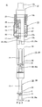
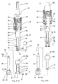
- the diametrically expanded groove cutting apparatus 11 shown in Figs. 1(a) and 1(b) includes a main body portion 12, an intermediate expandable mechanism 13 and a tip end side expandable mechanism 14, and a shank 1a formed at an upper portion of the main body portion 12 can be used by being attached to a chuck of an electrical device (driving portion, not shown).
- the electrical device applies, for example, rotations and impact vibrations to the diametrically expanded groove cutting apparatus 11.
- Fig. 1(a) is a partially cross sectional front view of the diametrically expanded groove cutting apparatus 11, showing a state where cutting blades 8 of the intermediate expandable mechanism 13 and the tip end side expandable mechanism 14 diametrically contract, and Fig.
- FIG. 1(b) is a partially cross sectional front view of the diametrically expanded groove cutting apparatus 11, showing a state where the cutting blades 8 diametrically expand.
- Fig. 2 is a partially cross sectional side view showing a diametrically contracted state of the diametrically expanded groove cutting apparatus 11 shown in Fig. 1(a) .
- the main body portion 12 is a rod-shaped body, a shank 1a is formed at its upper portion, and an attaching portion 12b is formed at its lower portion.
- the intermediate expandable mechanism 13 and a biasing mechanism 15 are attached to the attaching portion 12b.
- the attaching portion 12b has a short cylindrical shape, and has an insertion hole 16 which opens at a center of a lower end surface thereof and extends in an axial direction so as to have a predetermined depth.
- a base end portion 17a of a core body 17 of the intermediate expandable mechanism 13 is inserted into this insertion hole 16, and the core body 17 is slidable in a vertical direction along the insertion hole 16.
- the insertion hole 16 has such an inner diameter that the core body 17 can be held so as not to move unstably.
- the core body 17 inserted into the insertion hole 16 has a coupling hole 17b, and a coupling pin 18 is inserted through the coupling hole 17b.
- the coupling pin 18 is inserted through a pair of elongate holes 19 formed on a peripheral wall of the attaching portion 12b.
- the coupling pin 18 locks the core body 17 such that the core body 17 does not rotate with respect to the attaching portion 12b around a center axis, and can couple the core body 17 to the attaching portion 12b.
- the pair of elongate holes 19 are formed so as to extend along a depth direction (axial direction) of the insertion hole 16, and the length of the elongate hole 19 defines a range in which the core body 17 to be inserted into the insertion hole 16 moves in an axial direction of the attaching portion 12b.
- an engaging concave portion 22 is formed at a lower end opening edge of the attaching portion 12b.
- the engaging concave portion 22 engages with an engaging convex portion 23.
- the engaging convex portion 23 is formed at an upper edge of an exterior portion 24 included in the intermediate expandable mechanism 13, and is shaped so as to correspond to the engaging concave portion 22.
- the engaging concave portion 22 has a back portion 22a which is wider than an entrance portion of the engaging concave portion 22, and the engaging convex portion 23 has an upper end portion 23a which is wider in horizontal width than a base end portion of the engaging convex portion 23.
- the main body portion 12 and the exterior portion 24 can be coupled to each other such that their respective end portions are in close contact with each other, and they can engage with each other such that the exterior portion 24 does not rotate with respect to the main body portion 12 around the center axis.
- a biasing mechanism 15 is attached to the attaching portion 12b.
- the biasing mechanism 15 biases the core body 17 of the intermediate expandable mechanism 13 in a downward direction (extending direction), and includes a main body side sleeve 25.
- An internally threaded portion 25a is formed on an inner peripheral surface of an upper portion of the main body side sleeve 25, and the internally threaded portion 25a threadedly engages with an externally threaded portion 12c formed on an outer peripheral surface of the attaching portion 12b. With this engagement, the main body side sleeve 25 is fixedly attached to the main body portion 12.
- a tubular lower portion 25b of the main body side sleeve 25 is formed so as to be spaced apart from an outer peripheral surface of the main body portion 12, and an upper end portion of a compression spring 26 is accommodated in this space.
- a lower end portion of the compression spring 26 is accommodated in a tubular upper portion 27a of a core body side sleeve 27.
- the tubular upper portion 27a is formed so as to be larger in diameter than the tubular lower portion 25b of the main body side sleeve 25.
- the core body side sleeve 27 has coupling holes 27b which are located so as to be opposed to each other, and the coupling pin 18 is inserted through the coupling holes 27b.
- the core body side sleeve 27 is movable in an axial direction (vertical direction) along an outer peripheral surface of the attaching portion 12b.
- the biasing mechanism 15 can bias the core body side sleeve 27 in the downward direction by the compression spring 26.
- the coupling pin 18 attached to the core body side sleeve 27 contacts a lower edge of the elongate hole 19 and is stopped at this lower end position.
- the core body 17 of the intermediate expandable mechanism 13 and the core body 20 of the tip end side expandable mechanism 14 extend downward so as to be in the extended state, and the cutting blades 8 disposed on the flexible portions 21 become the diametrically contracted state.
- Fig. 1(a) the biasing mechanism 15 can bias the core body side sleeve 27 in the downward direction by the compression spring 26.
- the intermediate expandable mechanism 13 includes the exterior portion 24 and the core body 17.
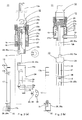
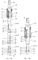
- Fig. 3(a) is a disassembled partially cross sectional front view of the intermediate expandable mechanism 13
- Fig. 3(b) is a disassembled partially cross sectional side view of the intermediate expandable mechanism 13.
- Fig. 4(a) is a partially cross sectional front view showing a state where the intermediate expandable mechanism 13 is attached to the main body portion 12, and Fig. 4(b) is its partially cross sectional side view.
- the exterior portion 24 includes a short cylindrical base end portion 24a, and the engaging convex portion 23 is formed at an upper edge of the base end portion 24a.
- One flexible portion 21 and one stiff portion 29 extending in the downward direction are formed at a lower portion of the base end portion 24a.
- the flexible portion 21 is formed by, for example, a plate-shaped metal having an elastic property, and is formed with a slide portion 30 at a lower end thereof.
- the slide portion 30 has the cutting blade 8 of a tip shape, and an edge portion of the cutting blade 8 project from an outer surface and lower end surface of the slide portion 30.
- An inner surface of the slide portion 30 which surface faces the core body 17 is formed as an inclined surface 30a so as to be inclined outward as it extends downward.
- the stiff portion 29 has a substantially semicircular shape in cross section and is formed so as to be longer than the flexible portion 21. As shown in Fig. 3(a) , each of inner surfaces of the flexible portion 21 and the stiff portion 29 is formed so as to have an arch shape in cross section such that a cylindrical portion of the core body 17 is slidably held.
- an engaging concave portion (that is an equivalent of the engaging concave portion 22 of the main body portion) 22 is formed at a lower edge of the stiff portion 29.
- the engaging convex portion 23 engages with the engaging concave portion 22.
- the engaging convex portion 23 (that is an equivalent of the engaging convex portion 23 formed at an upper edge of the intermediate expandable mechanism 13) is formed on an upper edge of an exterior portion 36 included in the tip end side expandable mechanism 14, and is shaped so as to correspond to the engaging concave portion 22.
- the core body 17 has the coupling hole 17b at its upper end portion and the expandable guiding portion 28 at its lower end portion, as described above.
- the expandable guiding portion 28 is formed as an inclined guiding groove for guiding the slide portion 30 in an expansion/contraction direction.
- a bottom surface 28a of the expandable guiding portion 28 widens outward in the downward direction, and the width of the bottom surface 28a has such a size as to be able to guide the slide portion 30 in the expansion/contraction direction without unstable movement.
- the bottom surface 28a has a projection 31.
- the projection 31 engages with an inner surface of the slide portion 30 such that the slide portion 30 is not displaced around the axis.
- the bottom surface 28a of the expandable guiding portion 28 is formed at such an angle that when the cutting blades 8 is in the diametrically expanded state, the bottom surface 28a is substantially in parallel with the inclined surface 30a formed on an inner surface of the slide portion 30 and contacts the substantially entire inclined surface 30a.
- the slide portion 30 is held so as not to be displaced with respect to the expandable guiding portion 28.
- a fitting hole 32 and a coupling hole 17c for coupling a lower end portion of the core body 17 and an upper end portion of the core body 20 of the tip end side expandable mechanism 14 are formed at the lower end portion of the core body 17.
- the upper end portion of the core body 20 fits in the fitting hole 32.
- the core body 17 and the core body 20 can be detachably coupled to each other by inserting a coupling pin 33 into the coupling hole 17c formed at the lower end portion of the core body 17 and a coupling hole 20a formed at the upper end portion of the core body 20 with the upper end portion of the core body 20 fitted in the fitting hole 32.
- a pin cover 34 shown in Figs. 1(a) and 6(a) is detachably attached to a lower end outer surface of the stiff portion 29.
- the tip end side expandable mechanism 14 includes the exterior portion 36 and the core body 20.
- Fig. 6(a) is a disassembled partially cross sectional front view of the tip end side expandable mechanism 14
- Fig. 6(b) is a disassembled partially cross sectional side view of the tip end side expandable mechanism 14.
- Fig. 7(a) is a partially cross sectional front view showing a state where the tip end side expandable mechanism 14 is attached to the intermediate expandable mechanism 13, and Fig. 7(b) is its partially cross sectional side view.
- Figs. 8(a) to 8(e) are diagrams showing the core body 20.
- the exterior portion 24 of the intermediate expandable mechanism 13 shown in Fig. 3(a) is configured to include one flexible portion 21 (the flexible portion 21 includes the slide portion 30 and the cutting blade 8) and one stiff portion 29 whereas the exterior portion 36 of the tip end side expandable mechanism 14 shown in Fig. 6(a) is configured to include two flexible portions 21 (each flexible portion 21 includes the slide portion 30 and the cutting blade 8) but not to include the stiff portion 29.
- an upper end portion where the coupling hole 17b is formed is formed so as to have the same diameter as a portion below this upper end portion.
- an upper end portion where the coupling hole 20a is formed is formed so as to be smaller in diameter than a portion below this upper end portion, and a step portion 37 is formed.
- the step portion 37 defines the fitting depth when the upper end of the core body 20 fits in the fitting hole 32 formed at the lower end of the core body 17.
- the core body 17 of the intermediate expandable mechanism 13 is configured to include the expandable guiding portion 28 on a left side of its lower end and the coupling hole 17c and the fitting hole 32 at the lower end portion.
- the core body 20 of the tip end side expandable mechanism 14 is configured to include two expandable guiding portions 28 on left and right sides of its lower end and a convex guide head 38 at the lower end portion but not to include the coupling hole 17c or the fitting hole 32.
- the guide head 38 has grooves 38a on its tip end surface. Except for these, the tip end side expandable mechanism 14 is the same as the intermediate expandable mechanism 13.
- the same reference numbers are used for the corresponding members, and explanations thereof are omitted.
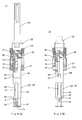
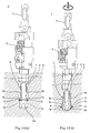
- a procedure of cutting two diametrically expanded annular grooves 3 on the inner peripheral wall of the anchor prepared hole 2 using the diametrically expanded groove cutting apparatus 11 shown in Figs. 1(a) and 1(b) configured as above will be explained with reference to Figs. 9 and 10 .
- the anchor prepared hole 2 is cut on the concrete floor surface 4 using a prepared hole drill 39, and the cutting powder 40 in the prepared hole 2 is discharged (cleaned).
- the shank 1a formed at the upper end of the diametrically expanded groove cutting apparatus 11 is attached to the chuck of the electrical device (rotation vibration driving portion), and as shown in Fig.
- the tip end side expandable mechanism 14 and the intermediate expandable mechanism 13 attached to the diametrically expanded groove cutting apparatus 11 are inserted into the anchor prepared hole 2.
- the guide head 38 that is a tip end portion of the diametrically expanded groove cutting apparatus 11 is pressed against the bottom of the anchor prepared hole 2.
- an operator drives the electrical device.
- the diametrically expanded groove cutting apparatus 11 rotates in a predetermined direction and is applied with vibration for applying impact on the bottom of the anchor prepared hole 2.
- the core bodies 17 and 20 coupled to each other are pushed upward against the spring force of the compression spring 26 (the exterior portions 24 and 36 are pressed downward).
- the diametrically expanded groove cutting apparatus 11 retracts.
- the pressing force of the tip end guide head 38 of the diametrically expanded groove cutting apparatus 11 with respect to the bottom of the anchor prepared hole 2 decreases, and the core bodies 17 and 20 are biased by the compression spring 26 so as to extend.
- the slide portions 30 disposed on the flexible portions 21 of the tip end side expandable mechanism 14 and the intermediate expandable mechanism 13 are guided by the expandable guiding portions 28 and diametrically contract while moving upward. With this, the cutting blades 8 disposed on the slide portions 30 diametrically contract. With the cutting blades 8 diametrically contracted, the tip end side expandable mechanism 14 and the intermediate expandable mechanism 13 can be pulled out from an anchor hole 41.
- the cutting powder 40 in the cut anchor hole 41 is discharged (cleaned).
- the anchor bar 42 such as a bolt
- a bonding material 43 such as epoxy
- the anchor bar 42 can be planted.
- the diametrically expanded groove cutting apparatus 11 the upper and lower diametrically expanded annular grooves 3 can be simultaneously cut on the inner peripheral wall of the anchor prepared hole 2. Therefore, it is possible to cut the anchor hole 41 allowing the high resistance to the pull-out force easily with less trouble and time.
- the intermediate expandable mechanism 13 of the diametrically expanded groove cutting apparatus 11 shown in Fig. 1(a) is detachably attached to the tip end side expandable mechanism 14 and the main body portion 12.
- the intermediate expandable mechanism 13 by detachably attaching the intermediate expandable mechanism 13 to another equivalent intermediate expandable mechanism 13, two intermediate expandable mechanisms 13 can be coupled to the lower portion of the main body portion 12, and the tip end side expandable mechanism 14 can be coupled to the lower portion of the intermediate expandable mechanism 13.
- three diametrically expanded annular grooves 3 can be cut simultaneously on the inner peripheral wall of the anchor prepared hole 2.
- a required number of the intermediate expandable mechanism 13 can be coupled to each other based on the number of the diametrically expanded annular grooves 3 to be cut.
- the step portion 37 is formed at the upper end of the core body 17 of the lower intermediate expandable mechanism 13, so that the tip end of the core body 17 is thin, as with the upper end of the core body 20 of the tip end side expandable mechanism 14 shown in Fig. 11(a) .
- the tip end side expandable mechanism 14 of the diametrically expanded groove cutting apparatus 11 shown in Fig. 1(a) can be configured to be detachably coupled to both the intermediate expandable mechanism 13 and the main body portion 12.
- the main body portion 12 can be directly coupled to the tip end side expandable mechanism 14 without being coupled to the intermediate expandable mechanism 13.
- one diametrically expanded annular groove 3 can be cut on the inner peripheral wall of the anchor prepared hole 2.
- the diametrically expanded groove cutting apparatus 11 which can cut one or a plurality of (a required number of) the diametrically expanded annular grooves 3 on the inner peripheral wall of the anchor prepared hole 2.
- the intermediate expandable mechanism shown in Fig. 3(a) has only one flexible portion 21, the cross-sectional area of the stiff portion 29 can be made large. Therefore, it is possible to improve the stiffness of the intermediate expandable mechanism 13. As above, in a case where the stiffness of the intermediate expandable mechanism 13 can be improved, the diameter of the intermediate expandable mechanism 13 can be comparatively made small, so that the diametrically expanded annular groove 3 can be cut on the anchor prepared hole 2 having a small diameter.
- the intermediate expandable mechanism 13 In a case where the diameter of the intermediate expandable mechanism 13 is comparatively made large, the cross-sectional area of the stiff portion 29 can be made large. Therefore, the intermediate expandable mechanism 13 can obtain a required strength. As a result, it is possible to provide the intermediate expandable mechanism configured to include a plurality of the flexible portions 21.
- the cutting blade 8 of the flexible portion 21 of the upper intermediate expandable mechanism 13 and the cutting blade 8 of the flexible portion 21 of the lower intermediate expandable mechanism 13 can be located so as to be opposed to each other with the core body 17 disposed therebetween. With this, the cutting resistance can be balanced, and the diametrically expanded annular grooves 3 can be cut stably.
- the main body portion 12, the exterior portion 24 of the intermediate expandable mechanism 13 and the exterior portion 36 of the tip end side expandable mechanism 14 shown in Fig. 1(a) are configured to be detachably coupled to one another. However, they may be fixedly coupled to one another.
- the core body 17 of the intermediate expandable mechanism and the core body 20 of the tip end side expandable mechanism 14 can be detachably coupled to each other. However, they may be fixedly coupled to each other.
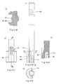
- Embodiment 2 of the diametrically expanded groove cutting apparatus according to the present invention will be explained with reference to Figs. 12 to 14 .
- a difference between the diametrically expanded groove cutting apparatus 11 of Embodiment 1 shown in Figs. 1(a) and 1(b) and a diametrically expanded groove cutting apparatus 111 of Embodiment 2 shown in Figs. 12(a) and 12(b) is a configuration in which in a case where the diametrically expanded cutting blades 8 do not return to the diametrically contracted state during cutting of the anchor hole 41, the diametrically expanded groove cutting apparatus inserted into the anchor hole 41 can be forcibly pulled out from the anchor hole 41.
- the diametrically expanded groove cutting apparatus 111 of Embodiment 2 is the same as the diametrically expanded groove cutting apparatus 11 of Embodiment 1.
- the same reference numbers are used for the corresponding members, and explanations thereof are omitted.
- the diametrically expanded groove cutting apparatus 11 of Embodiment 1 in a case where the diametrically expanded cutting blades 8 do not return to the diametrically contracted state during cutting of the anchor hole 41, the main body side sleeve 25 is rotated in a predetermined direction relatively with respect to the main body portion 12 using, for example, two wrenches.
- the cutting blades 8 it is possible to forcibly cause the cutting blades 8 to move upward and to diametrically contract. Therefore, the diametrically expanded groove cutting apparatus 11 inserted into the anchor hole 41 can be pulled out from the anchor hole 41.
- an inner peripheral surface of a main body side sleeve 125 disposed on the diametrically expanded groove cutting apparatus 111 of Embodiment 2 has a short cylindrical shape, and an outer peripheral surface of the main body portion 12 inserted into the main body side sleeve 125 also has a short cylindrical shape. Therefore, the main body side sleeve 125 is movable in the axial direction (vertical direction) along the main body portion 12. The upward movement of the main body side sleeve 125 is stopped at a position of a stopper projection 50 formed on the outer peripheral surface of the main body portion 12.
- the tubular upper portion 27a of the core body side sleeve 27 overlaps with the tubular lower portion 25b of the main body side sleeve 125 so as to cover the tubular lower portion 25b, and an upper edge of the tubular upper portion 27a contacts an engaging convex portion 51 of the main body side sleeve 125.
- the cotter hole 49 is an elongate hole which passes through the main body portion 12 and has a predetermined length, and formed to extend along the axial direction of the main body portion 12.
- the upper edge of the main body side sleeve 125 is in contact with the stopper projection 50, the lower portion of the cotter hole 49 is covered by the main body side sleeve 125, and the upper portion of the cotter hole 49 is open.
- the main body side sleeve 125 and the core body side sleeve 27 are in contact with each other, and the cutting blades 8 diametrically expand.
- the upper portion of the cotter hole 49 opens outside in the state of Fig. 14(a) . Therefore, by hitting the cotter 52 into the opening of the cotter hole 49, as shown in Fig. 14(b) , it is possible to cause the core bodies 17 and 20 to extend and to forcibly cause the diametrically expanded cutting blades 8 to diametrically contract.
- the diametrically expanded cutting blades 8 of the diametrically expanded groove cutting apparatus 111 do not return to the diametrically contracted state shown in Fig. 14(b) by the spring force of the compression spring 26, and the diametrically expanded groove cutting apparatus 111 cannot be pulled out from the anchor hole 41, forcibly causing the cutting blades 8 to diametrically contract and pulling out the diametrically expanded groove cutting apparatus 111 from the anchor hole 41 as shown in Fig. 14(b) .
- the reason why the diametrically expanded cutting blades 8 do not return to the diametrically contracted state by the spring force of the compression spring 26 may be because, for example, the cutting powder 40 clogs between the slide portions 30 and the expandable guiding portions 28.
- a tip end portion of the cotter 52 is hit into the upper portion of the cotter hole 49 which opens above the main body side sleeve 125.
- an upper edge 52a of the cotter 52 presses up the upper edge of the cotter hole 49 (the main body portion 12).
- a lower edge 52b of the cotter 52 contacts the upper edge of the main body side sleeve 125, so that the main body side sleeve 125 can remain at an original height position so as not to move upward.
- the slide portions 30 coupled to the main body portion 12 can be caused to move relatively upward along the expandable guiding portions 28.
- the diametrically expanded cutting blades 8 can be forcibly contracted extremely easily in a short period of time, and the diametrically expanded groove cutting apparatus 111 can be easily pulled out from the anchor hole 41.
- the cotter hole 49 is formed on the main body portion 12.
- a cotter groove having the same function as the cotter hole 49 may be formed on the main body portion 12.
- the diametrically expanded groove cutting apparatus and the expandable mechanism used therein have an excellent effect of being able to cut a plurality of diametrically expanded annular grooves simultaneously on the inner peripheral wall of the anchor prepared hole for planting the anchor bar therein and an excellent effect of being able to easily pull out from the anchor hole in a short period of time the diametrically expanded groove cutting apparatus which has diametrically expanded and does not diametrically contract by, for example, the cutting powder, and are suitable for being applied to such a diametrically expanded groove cutting apparatus and an expandable mechanism used therein.
Landscapes
- Engineering & Computer Science (AREA)
- Mining & Mineral Resources (AREA)
- Mechanical Engineering (AREA)
- Structural Engineering (AREA)
- Life Sciences & Earth Sciences (AREA)
- General Life Sciences & Earth Sciences (AREA)
- Geochemistry & Mineralogy (AREA)
- Geology (AREA)
- Processing Of Stones Or Stones Resemblance Materials (AREA)
- Earth Drilling (AREA)
Applications Claiming Priority (3)
| Application Number | Priority Date | Filing Date | Title |
|---|---|---|---|
| JP2005329288 | 2005-11-14 | ||
| JP2006064877 | 2006-03-09 | ||
| PCT/JP2006/322553 WO2007055353A1 (ja) | 2005-11-14 | 2006-11-13 | 拡径溝削成装置及び拡縮機構具 |
Publications (1)
| Publication Number | Publication Date |
|---|---|
| EP1959091A1 true EP1959091A1 (de) | 2008-08-20 |
Family
ID=38023345
Family Applications (1)
| Application Number | Title | Priority Date | Filing Date |
|---|---|---|---|
| EP06823327A Withdrawn EP1959091A1 (de) | 2005-11-14 | 2006-11-13 | Nutenschneidvorrichtung mit durchmesseraufweitung und werkzeug mit aufweit-/zusammenziehmechanismus |
Country Status (7)
| Country | Link |
|---|---|
| US (1) | US20090139772A1 (de) |
| EP (1) | EP1959091A1 (de) |
| JP (1) | JPWO2007055353A1 (de) |
| KR (1) | KR20080066738A (de) |
| AU (1) | AU2006312579A1 (de) |
| CA (1) | CA2623249A1 (de) |
| WO (1) | WO2007055353A1 (de) |
Cited By (4)
| Publication number | Priority date | Publication date | Assignee | Title |
|---|---|---|---|---|
| WO2010095137A1 (en) * | 2009-02-19 | 2010-08-26 | Y.D.E. Engineers Ltd. | Nibbling mechanism for construction material |
| FR2976512A1 (fr) * | 2011-06-20 | 2012-12-21 | Airbus Operations Sas | Dispositif de reparation de defauts dans une structure |
| CN112606109A (zh) * | 2020-12-15 | 2021-04-06 | 梁绍丽 | 一种在制造家具板材上钻取t形孔的方法 |
| EP4357532A1 (de) * | 2022-10-21 | 2024-04-24 | Spinnanker GmbH | Eindrehsystem für die einbringung eines gewindestabes in einen untergrund |
Families Citing this family (9)
| Publication number | Priority date | Publication date | Assignee | Title |
|---|---|---|---|---|
| US20120074659A1 (en) | 2010-09-29 | 2012-03-29 | Henry H. Hamilton | Tool assembly and related methods |
| US8857036B2 (en) * | 2011-03-07 | 2014-10-14 | GM Global Technology Operations LLC | Leak-tight connection between pipe and port |
| CA2790694C (en) * | 2012-09-20 | 2015-07-21 | Robert Cousineau | Self-undercut expansion anchor insertion system |
| WO2014205578A1 (en) * | 2013-06-25 | 2014-12-31 | Robert Cousineau | Self-undercut anchor system |
| CN104453720A (zh) * | 2014-12-19 | 2015-03-25 | 五广(上海)基础工程有限公司 | 两段式旋挖扩底钻头 |
| JP6651418B2 (ja) | 2016-07-07 | 2020-02-19 | 株式会社ミヤナガ | 拡径孔部の穿孔装置 |
| JP7079475B2 (ja) * | 2018-02-14 | 2022-06-02 | 株式会社ミヤナガ | 拡径孔部の穿孔装置 |
| EP4416341B1 (de) * | 2021-10-14 | 2025-08-20 | Hubbell Incorporated | Verriegelungsbügelanordnung |
| CN119426706B (zh) * | 2025-01-10 | 2025-03-25 | 山西纵横门窗有限公司 | 一种断桥铝窗加工切割装置及切割方法 |
Family Cites Families (6)
| Publication number | Priority date | Publication date | Assignee | Title |
|---|---|---|---|---|
| US2654575A (en) * | 1950-01-09 | 1953-10-06 | Archer W Kammerer | Tandem expansible rotary drill bit |
| JPS6278393A (ja) * | 1985-09-30 | 1987-04-10 | 国土防災技術株式会社 | 多段式拡孔ビツト |
| JP2564100Y2 (ja) * | 1989-07-29 | 1998-03-04 | 株式会社 ミヤナガ | アンカーボルト植設用孔の拡径部削成装置 |
| JP3021129U (ja) * | 1995-07-31 | 1996-02-16 | シンエイテック株式会社 | 掘削装置の連結機構 |
| JP3242339B2 (ja) * | 1996-12-06 | 2001-12-25 | 敏雄 向井 | 掘削機用排土部材の接続装置 |
| JP3949019B2 (ja) * | 2002-07-17 | 2007-07-25 | 株式会社技研製作所 | オーガ |
-
2006
- 2006-11-13 EP EP06823327A patent/EP1959091A1/de not_active Withdrawn
- 2006-11-13 JP JP2007544216A patent/JPWO2007055353A1/ja not_active Withdrawn
- 2006-11-13 CA CA002623249A patent/CA2623249A1/en not_active Abandoned
- 2006-11-13 WO PCT/JP2006/322553 patent/WO2007055353A1/ja not_active Ceased
- 2006-11-13 AU AU2006312579A patent/AU2006312579A1/en not_active Abandoned
- 2006-11-13 US US12/092,073 patent/US20090139772A1/en not_active Abandoned
- 2006-11-13 KR KR1020087010329A patent/KR20080066738A/ko not_active Ceased
Non-Patent Citations (1)
| Title |
|---|
| See references of WO2007055353A1 * |
Cited By (5)
| Publication number | Priority date | Publication date | Assignee | Title |
|---|---|---|---|---|
| WO2010095137A1 (en) * | 2009-02-19 | 2010-08-26 | Y.D.E. Engineers Ltd. | Nibbling mechanism for construction material |
| FR2976512A1 (fr) * | 2011-06-20 | 2012-12-21 | Airbus Operations Sas | Dispositif de reparation de defauts dans une structure |
| US8707834B2 (en) | 2011-06-20 | 2014-04-29 | Airbus Operations S.A.S. | Device for repair of defects in a structure |
| CN112606109A (zh) * | 2020-12-15 | 2021-04-06 | 梁绍丽 | 一种在制造家具板材上钻取t形孔的方法 |
| EP4357532A1 (de) * | 2022-10-21 | 2024-04-24 | Spinnanker GmbH | Eindrehsystem für die einbringung eines gewindestabes in einen untergrund |
Also Published As
| Publication number | Publication date |
|---|---|
| US20090139772A1 (en) | 2009-06-04 |
| CA2623249A1 (en) | 2007-05-18 |
| AU2006312579A1 (en) | 2007-05-18 |
| JPWO2007055353A1 (ja) | 2009-04-30 |
| KR20080066738A (ko) | 2008-07-16 |
| WO2007055353A1 (ja) | 2007-05-18 |
Similar Documents
| Publication | Publication Date | Title |
|---|---|---|
| EP1959091A1 (de) | Nutenschneidvorrichtung mit durchmesseraufweitung und werkzeug mit aufweit-/zusammenziehmechanismus | |
| AU2022275505B2 (en) | Steel pipe coupling device for steel pipes | |
| EP3128105B1 (de) | Verfahren zum einspritzen von injektionsfüllstoff in eine betonstruktur und spritze dafür | |
| EP0567254B1 (de) | Betonanker | |
| JP4445506B2 (ja) | ブラインド締結具および該ブラインド締結具を被加工物から抜き取る方法 | |
| US20160008966A1 (en) | Vibration reduction mechanism for a striking tool | |
| JP2008183707A (ja) | あと施工アンカーのための下孔加工用ドリルビット | |
| JP2015533664A (ja) | ドロップインアンカーの取付工具 | |
| AU2002338538B2 (en) | Method and device for drilling a hole and for securing an anchorage in a bore hole | |
| JP2862807B2 (ja) | アンダーカット部付き孔の穿孔装置 | |
| KR20180108105A (ko) | 코어드릴용 확장코어비트 | |
| CN101292074A (zh) | 扩径槽切削成装置及扩缩机构工具 | |
| IT201900012105A1 (it) | Dispositivo di giunzione in particolare per mobili | |
| JP2018524177A (ja) | フロー成形リベットスリーブを使用して少なくとも2つの部品を接合するための方法及び接合要素 | |
| JP7670451B2 (ja) | 穿孔拡径工具 | |
| KR102306287B1 (ko) | 클린칭 펀치 | |
| HK1121216A (en) | Diameter expanding groove cutting device and expanding/contracting mechanism tool | |
| AU693051B2 (en) | Apparatus for drilling a hole having an undercut space | |
| JP3947125B2 (ja) | 本体打込み式アンカー | |
| JPH0110174Y2 (de) | ||
| JP6836784B2 (ja) | アンカー打込み工具 | |
| KR101899301B1 (ko) | 그라우팅 공법을 위한 소일 네일과 스페이서의 결합 구조 | |
| CA2892596A1 (en) | Expandable bolt with thrust element | |
| JP6923879B2 (ja) | 拡径孔部付き孔の穿孔装置 | |
| KR101693167B1 (ko) | 굴착용 비트 |
Legal Events
| Date | Code | Title | Description |
|---|---|---|---|
| PUAI | Public reference made under article 153(3) epc to a published international application that has entered the european phase |
Free format text: ORIGINAL CODE: 0009012 |
|
| 17P | Request for examination filed |
Effective date: 20080331 |
|
| AK | Designated contracting states |
Kind code of ref document: A1 Designated state(s): DE FR GB |
|
| DAX | Request for extension of the european patent (deleted) | ||
| RBV | Designated contracting states (corrected) |
Designated state(s): DE FR GB |
|
| STAA | Information on the status of an ep patent application or granted ep patent |
Free format text: STATUS: THE APPLICATION IS DEEMED TO BE WITHDRAWN |
|
| 18D | Application deemed to be withdrawn |
Effective date: 20100601 |