EP1957794B1 - Elektrokinetische pumpenausführungen und arzneimittelabgabesysteme - Google Patents
Elektrokinetische pumpenausführungen und arzneimittelabgabesysteme Download PDFInfo
- Publication number
- EP1957794B1 EP1957794B1 EP20060838337 EP06838337A EP1957794B1 EP 1957794 B1 EP1957794 B1 EP 1957794B1 EP 20060838337 EP20060838337 EP 20060838337 EP 06838337 A EP06838337 A EP 06838337A EP 1957794 B1 EP1957794 B1 EP 1957794B1
- Authority
- EP
- European Patent Office
- Prior art keywords
- housing
- pump
- delivery
- piston
- fluid
- Prior art date
- Legal status (The legal status is an assumption and is not a legal conclusion. Google has not performed a legal analysis and makes no representation as to the accuracy of the status listed.)
- Not-in-force
Links
Images

Classifications
-
- F—MECHANICAL ENGINEERING; LIGHTING; HEATING; WEAPONS; BLASTING
- F04—POSITIVE - DISPLACEMENT MACHINES FOR LIQUIDS; PUMPS FOR LIQUIDS OR ELASTIC FLUIDS
- F04B—POSITIVE-DISPLACEMENT MACHINES FOR LIQUIDS; PUMPS
- F04B19/00—Machines or pumps having pertinent characteristics not provided for in, or of interest apart from, groups F04B1/00 - F04B17/00
- F04B19/04—Pumps for special use
-
- A—HUMAN NECESSITIES
- A61—MEDICAL OR VETERINARY SCIENCE; HYGIENE
- A61M—DEVICES FOR INTRODUCING MEDIA INTO, OR ONTO, THE BODY; DEVICES FOR TRANSDUCING BODY MEDIA OR FOR TAKING MEDIA FROM THE BODY; DEVICES FOR PRODUCING OR ENDING SLEEP OR STUPOR
- A61M5/00—Devices for bringing media into the body in a subcutaneous, intra-vascular or intramuscular way; Accessories therefor, e.g. filling or cleaning devices, arm-rests
- A61M5/14—Infusion devices, e.g. infusing by gravity; Blood infusion; Accessories therefor
- A61M5/142—Pressure infusion, e.g. using pumps
- A61M5/145—Pressure infusion, e.g. using pumps using pressurised reservoirs, e.g. pressurised by means of pistons
- A61M5/1452—Pressure infusion, e.g. using pumps using pressurised reservoirs, e.g. pressurised by means of pistons pressurised by means of pistons
- A61M5/14526—Pressure infusion, e.g. using pumps using pressurised reservoirs, e.g. pressurised by means of pistons pressurised by means of pistons the piston being actuated by fluid pressure
-
- F—MECHANICAL ENGINEERING; LIGHTING; HEATING; WEAPONS; BLASTING
- F04—POSITIVE - DISPLACEMENT MACHINES FOR LIQUIDS; PUMPS FOR LIQUIDS OR ELASTIC FLUIDS
- F04B—POSITIVE-DISPLACEMENT MACHINES FOR LIQUIDS; PUMPS
- F04B17/00—Pumps characterised by combination with, or adaptation to, specific driving engines or motors
-
- F—MECHANICAL ENGINEERING; LIGHTING; HEATING; WEAPONS; BLASTING
- F04—POSITIVE - DISPLACEMENT MACHINES FOR LIQUIDS; PUMPS FOR LIQUIDS OR ELASTIC FLUIDS
- F04B—POSITIVE-DISPLACEMENT MACHINES FOR LIQUIDS; PUMPS
- F04B19/00—Machines or pumps having pertinent characteristics not provided for in, or of interest apart from, groups F04B1/00 - F04B17/00
- F04B19/006—Micropumps
-
- A—HUMAN NECESSITIES
- A61—MEDICAL OR VETERINARY SCIENCE; HYGIENE
- A61M—DEVICES FOR INTRODUCING MEDIA INTO, OR ONTO, THE BODY; DEVICES FOR TRANSDUCING BODY MEDIA OR FOR TAKING MEDIA FROM THE BODY; DEVICES FOR PRODUCING OR ENDING SLEEP OR STUPOR
- A61M5/00—Devices for bringing media into the body in a subcutaneous, intra-vascular or intramuscular way; Accessories therefor, e.g. filling or cleaning devices, arm-rests
- A61M5/14—Infusion devices, e.g. infusing by gravity; Blood infusion; Accessories therefor
- A61M5/142—Pressure infusion, e.g. using pumps
- A61M5/145—Pressure infusion, e.g. using pumps using pressurised reservoirs, e.g. pressurised by means of pistons
- A61M2005/14513—Pressure infusion, e.g. using pumps using pressurised reservoirs, e.g. pressurised by means of pistons with secondary fluid driving or regulating the infusion
-
- A—HUMAN NECESSITIES
- A61—MEDICAL OR VETERINARY SCIENCE; HYGIENE
- A61M—DEVICES FOR INTRODUCING MEDIA INTO, OR ONTO, THE BODY; DEVICES FOR TRANSDUCING BODY MEDIA OR FOR TAKING MEDIA FROM THE BODY; DEVICES FOR PRODUCING OR ENDING SLEEP OR STUPOR
- A61M2209/00—Ancillary equipment
- A61M2209/04—Tools for specific apparatus
- A61M2209/045—Tools for specific apparatus for filling, e.g. for filling reservoirs
-
- Y—GENERAL TAGGING OF NEW TECHNOLOGICAL DEVELOPMENTS; GENERAL TAGGING OF CROSS-SECTIONAL TECHNOLOGIES SPANNING OVER SEVERAL SECTIONS OF THE IPC; TECHNICAL SUBJECTS COVERED BY FORMER USPC CROSS-REFERENCE ART COLLECTIONS [XRACs] AND DIGESTS
- Y10—TECHNICAL SUBJECTS COVERED BY FORMER USPC
- Y10T—TECHNICAL SUBJECTS COVERED BY FORMER US CLASSIFICATION
- Y10T137/00—Fluid handling
- Y10T137/0318—Processes
- Y10T137/0391—Affecting flow by the addition of material or energy
Definitions
- Pumps and pumping systems exist for the delivery of various fluids.
- a variety of pumps are used in a number of various different configurations and uses. Pumps are used for infusion of drugs or delivery of drugs into mammals, the sterility of the drugs is very important. In addition, contamination of the drug or delivery fluid from the pump system should be reduced or eliminated. Additionally, it remains an important aspect to minimize contact between the drug to be delivered and the internal components of the pump being used to deliver the drug. Filling or preparing the drug or fluid for delivery should not be time consuming. These and other difficulties are encountered using conventional filling and pumping systems.
- US2004/0074768 relates to an electrokinetic pump having capacitive electrodes.
- the present invention provides a piston assembly having a piston housing; a further housing within the piston housing that divides the piston housing into a first portion and a second portion, the further housing having apertures that provide fluid communication between the first portion and the second portion; a first shaft connecting the housing to a piston head outside of the piston housing; and a porous dielectric material inside of the housing.
- the piston housing is filled with an electrolyte.
- the porous material inside of the further housing is in contact with the electrolyte.
- the porous material is a porous dielectric material adapted for operation as part of an electrokinetic pump.
- there is a valve within the second shaft wherein actuation of the valve provides a flow path between the first portion and the second portion.
- the flow path from one side of the housing to the other side of the housing includes a bypass through the porous material contained in the housing.
- the valve is actuatable from a handle attached to the second shaft.
- the shaft extends through a wall in the piston housing.
- the sealing element around the further housing seals the housing to a wall of the piston housing.
- the electrodes have a double layer capacitance of greater than 10 -4 microfarad/cm 2 .
- the piston assembly from above may form part of a pump, said pump having a delivery chamber, a pump chamber and a wall separating the pump chamber from the delivery chamber; the piston assembly from above having a piston head in the delivery chamber, a housing in the pump chamber and a shaft connecting the piston head to the housing and passing through the wall separating the pump chamber from the delivery chamber; and a dielectric material in the housing.
- each electrode in the pair of electrodes has a double layer capacitance of more than 10 -4 microfarad/cm 2 .
- bypass valve in the shaft that provides a fluid pathway from one side of the housing to the other side of the housing.
- the bypass valve in the shaft that provides a fluid pathway from the first portion to the second portion.
- the delivery chamber is filled with a delivery fluid by relative movement between the pump chamber and the delivery chamber.
- application of an electric field across the electrodes moves the fluid in the pump chamber from one side of the housing to the other side of the housing.
- application of an electric field across the electrodes moves the piston head in the delivery chamber.
- application of an electric field across the electrodes moves the housing relative to the pump chamber.
- a method for operating a fluid delivery assembly having a pump chamber and a delivery chamber by withdrawing a shaft from within the fluid delivery assembly to simultaneously displace a moving pump element within the delivery chamber and bypass fluid around a housing in the pump chamber.
- withdrawing a shaft from the pump assembly introduces a delivery fluid into the delivery chamber and into contact with the moving pump element.
- advancing the moving pump element in the delivery chamber by applying an electrical field across electrodes in the pump chamber and on either side of the housing causes a delivery fluid to flow out of the delivery chamber.
- Still another aspect provides electrokineticly moving fluid in the pump chamber to dispense fluid from the delivery chamber.
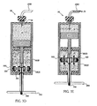
- FIGs. 1A and 1B will be described to provide an understanding of the basic components and operation of a typical fluid delivery system.
- FIG. 1A illustrates a cross section view of a fluid delivery system 1.
- the fluid delivery system has a first chamber 30, a second chamber 32 and a third chamber 35.
- a flow through pump element 20 (such as electrokinetic pump, as shown in FIG. 1B ) separates the first chamber 30 from the second chamber 32.
- a moveable pump element 40 (such as a floating piston, as shown) separates the second chamber 32 from the third chamber 35. While in this illustrative embodiment the moveable element 40 is a floating piston, any device that provides a moveable barrier may be used as will be illustrated in the examples that follow.
- first, the second and the third chambers are within a single housing 15.
- Seals 42 are used to seal the moveable pump element 40 as it moves within the housing 15.
- An outlet 45 provides communication between the third chamber 35 and the exterior of housing 15.
- An outlet 55 provides communication between the second chamber 32 and the exterior of housing 15.
- a valve 60 separates the second outlet 55 from the exterior of housing 15.
- a conduit 71 connects the outlet 55 to the opening 70.
- a valve 60 in the conduit 71 controls fluid flow from the outlet 55 to the opening 70.
- the valve 60 has a disc 62, stem 64, a spring 66 and a disc or seal 68.
- Seats 72, 74 in the housing are shaped to seal with, respectively, discs or seals 62, 68.
- Valve 60 is shown in the closed position where spring 66 holds discs 68, 62 in place against seats 72, 74.
- conduit 71 and valve 60 are disposed in a wall of housing 15.
- Other configurations are possible such as a separate valve assembly that attaches directly to port 55 or a valve/conduit configuration that ports through the pump element 20 rather than around the pump element 20 as shown.
- the first chamber 30 contains a moveable pump element 82 (i.e., a diaphragm adjacent the pump element 20).
- the first chamber 30 also contains a vent 75, if needed to ensure free movement of the moveable element 82.
- the space between the diaphragm 82 and the pump element 20 contains a buffer or pump fluid 80 that is selected to operate with the type of pump element used. If the pump element 20 is an electrokinetic pump, then the buffer 80 would be an electrolyte selected to operate with the electrode and porous material materials and desired operation of the pump. Examples of specific electrolytes and other details of electrokinetic pumps are described in commonly assigned patent numbers U.S. Patent No.
- the pump element 20 is connected to supporting electronics 5 by electrical connectors 26.
- the supporting electronics 5 may be altered depending upon the type of pump element(s) used but will generally include a user control interface 6, electronic control circuitry 8 and a power supply 10.
- the user control interface 6 may be a touch screen or other input means to allow a user to operate the delivery system, select a program or otherwise provide programming instructions to the system.
- the electronic control circuitry contains the programming instructions needed to translate the user inputs into commands to operate the pump element.
- the electronic control circuitry also regulates the power supply to achieve user desired pumping characteristics such as flow rate and delivery timing.
- the power supply 10 may contain a battery or the delivery system may be plugged into an electrical supply.
- the supporting electronics are conventional and will be understood by those of ordinary skill in the art.
- FIG. 1B An exploded view of one type of pump element 20 is shown in FIG. 1B .
- the pump element 20 shown in FIG. 1B is an electrokinetic pump element.
- Electrokinetic pump element contains a porous material 22 between two capacitive electrodes 24.
- Illustrative electrode materials include carbon aero gel or carbon nanofoam.
- One example of a suitable porous membrane is a microporous filter having a pore size ranging from tens of nanometers to micron size. In one embodiment, the preferred pore size is 100-200 nanometers.
- the capacitive electrodes are connected to the supporting electronics 5 by electrical connectors 26.
- the pump element contains a pump fluid or buffer 80 that is moved through the porous material 22 from one electrode towards the other electrode depending on how voltage is applied between the electrodes 24.
- the electrokinetic flow produced by the pump element 20 may be in one direction (from one electrode to the other electrode) or may alternate directions of flow (towards one electrode and then away from that electrode and towards the other electrode).
- electrokinetic pumps configurations, electrolytes, electrodes, porous materials (also referred to as porous dielectric materials) and other details of are described in commonly assigned patents: U.S. Patent No. 7,364,647, filed July 17, 2002 titled, “Laminated Flow Devices"; U.S. Patent No. 7,235,164 filed October 18, 2002 titled, "Electrokinetic Device Having Capacitive Electrodes”; U.S. Patent No. 7,267,753 filed December 17, 2002 titled, “Electrokinetic Device Having Capacitive Electrodes” and U.S. Patent No. 7,517,440 filed April 21, 2005 titled, “Electrokinetic Delivery Systems, Devices and Methods”.
- a storage fluid 50 fills the second chamber.
- the storage fluid 50 may be a fluid used to maintain the integrity of the pump element 20 during storage or prior to operation.
- the storage fluid 50 may be the same or different than the fluid 80 stored in the first chamber.
- the storage fluid 50 may also be a pump fluid (i.e., such as electrolyte suited to operation in an electrokinetic pump) moved by operation of the pump element 20.
- a delivery fluid 36 is stored in the third chamber 35.
- the delivery fluid is a drug, a pharmacological or therapeutic agent, or other substance to be delivered by operation of the pump element 20.
- FIG. 1A also illustrates a conventional syringe 90 is also illustrated having a body 91 with a tip 92.
- a plunger 93 is attached to handle 95 by shaft 94 is disposed within the body 91.
- Pump system 1 provides one solution to loading the pump system without the use of the pump element 20 by bypassing the pump element. Additionally, the pump element 20 remains in a fixed position within the pump housing during both filling and pumping operations.
- the pump systems 900 and 1000 provide an alternative apparatus and method for filling and delivering fluid. In contrast to the fixed pump element fluid system 1, the pump element in pump systems 900, 1000 moves within the pump housing during fluid delivery operations. The pump element in fluid system 1000 also moves during pump filling operations.
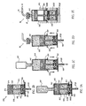
- FIGs. 2A-D and FIGs. 3A-E illustrate pumping systems 900, 1000.
- Novel piston assemblies are at the heart of the systems.
- the piston assemblies are designed to move within another pump component to deliver fluid.
- Piston assembly 970 (illustrated in FIG. 2B ) and piston assembly 990 (illustrated in FIG. 3B ) have several common components.
- a piston head 972 is connected to a further housing 980 by a first shaft 976.
- the housing 980 contains a porous material 984 and a plurality of apertures 982 allow fluid flow through the housing 980 and the porous material 984.
- the porous material 984 is a dielectric material which may be adapted for operation as part of an electrokinetic pump. Examples of porous dielectric materials described in the commonly assigned patents described above.
- a sealing element or elements 974 are provided around the perimeter of the piston head 972.
- the piston head 972 is sealed within a delivery chamber that is separate from the pump chamber (i.e., delivery chamber 910 in FIG. 2A ) or integrally formed with the pump chamber (i.e., delivery chamber 1010 in FIG. 3A ).
- One or more sealing elements 978 is provided around the perimeter of the housing 980.
- the housing 980 is sealed within the pump chamber using sealing elements 978 as shown in FIGs, 2A and 3A .
- Suitable materials for construction of components include polypropylene, polycarbonate and medical grade plastics.
- FIG. 2A illustrates a pump 900 that includes a delivery chamber 910, a pump chamber or piston housing 950 and a wall 931 separating the pump chamber 950 from the delivery chamber 910.
- the piston housing 950 is filled with a suitable electrolyte 80.
- a piston assembly 970 has a piston head 972 in the delivery chamber 910 (i.e., outside of the pump housing 950), a housing 980 in the piston housing or pump chamber 950 and a shaft 976 connecting the piston head 972 to the housing 980.
- the shaft 976 passes through the wall 931 separating the piston housing 950 from the delivery chamber 910.
- the housing 980 divides the piston housing 950 into a first portion 950A and a second portion 950B.
- a pair of electrodes 924 are in the pump housing 950 where there is one electrode 924 is on each side of the housing 980. There is an electrode 924 in the first portion 950A and an electrode 924 in the second portion 950B. In one embodiment, each electrode in the pair of electrodes has a double layer capacitance of more than 10 -4 microfarad/cm 2 .
- a porous material 984 is contained inside of the housing 980 and in contact with the electrolyte 80.
- the housing 980 has apertures 982 that provide fluid communication between the first portion 950A and a second portion 950B.
- the housing 980 is sealed within the piston housing 950 using sealing element 978.
- the housing 910 includes an outlet 945 and an interior space 915.
- the interior space 915 is sized and shaped to sealingly receive the piston head 972.
- the piston housing 950 is adapted for pumping operations using the piston assembly 970.
- the housing 950 includes electrodes 924 positioned on either end of housing interior.
- the piston assembly 970 is disposed within the housing 950 with shaft 976 extending through a sealed opening 943.
- the housing 950 is inserted into the interior space 915 and the piston 972 is advanced against the interior 915 adjacent the outlet 945.
- the pump system 900 is now ready for filling.
- the pump system 900 is filled by attaching a vial 105 or other suitable container to the outlet 945 and then withdrawing the piston housing 950 from the delivery interior 915 as indicated by the arrow in FIG. 2C .
- the relative movement of the pump chamber 950 to the delivery chamber 910 draws the delivery fluid 36 from vial 105 through the outlet 945 and into the interior 915 as shown in FIG. 2C .
- the vial 105 is removed and a delivery device, such as an infusion set 96, is attached to outlet 945.
- An optional purge or prime procedure is illustrated in FIG. 2D .
- the system Before attachment of the delivery device, after attachment of the delivery device or both before and after attachment of the delivery device the system may be primed or purged of air by advancing the piston housing 950 relative to the delivery chamber 910 as indicated by the arrows in FIG. 2D .
- the position of the piston housing 950 is fixed relative to the delivery chamber 910.
- the housings 910, 950 are fixed when feature 912 on delivery chamber 910 and feature 934 on chamber 950 are locked in place using bars 492 and spaces 494 within the frame 490 as illustrated in FIG. 2E .
- Electrode Pumping begins when an electric field is applied across electrodes 924.
- Application of an electric field across the electrodes 924 moves electrolyte 80 in the piston housing 950 from one side of the housing 980 (i.e., the portion 950B) to the other side of the housing (i.e. the portion 950A).
- the electrolyte 80 is moved electrokineticly through the apertures 982 and the porous material 984 from one electrode 924 towards the other as indicated by the arrows in FIG. 2E .
- This movement of the electrolyte decreases the volume of the portion 950B and increases the volume of the portion 950A.
- Increasing volume of portion 950A moves the housing 980 and the piston head 972 towards the outlet 945 which in turn expels delivery fluid 36 out through outlet 945.
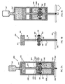
- the pumping system 1000 includes a delivery chamber 1010 and a pump chamber 1020 within a single housing (i.e., the pump housing 1005).
- the delivery chamber 1010 has an outlet 1045 and a vent 1012.
- a vial 105 filled with a delivery fluid 36 is attached to outlet 1045 and the pump system 1000 is ready for filling.
- the piston assembly 990 illustrated in FIG. 3B , is disposed within the pump housing 1005.
- the piston assembly 990 is arranged within a piston housing or pump chamber 1020 filled with an electrolyte 80.
- a housing 980 within the piston housing divides the piston housing into a first portion 980A and a second portion 980B and maintained by seals 978.
- the housing 980 has apertures 982 that provide fluid communication between the first portion 980A and the second portion 980B.
- the housing 980 contains a porous dielectric material 984 in communication with the electrolyte 80.
- the porous material 984 may be adapted for operation as part of an electrokinetic pump.
- a pair of electrodes 1024 are provided in the pump chamber 1020.
- One electrode 1024 is provided on each side of the housing 980 (i.e., one electrode in the first portion 980A and one electrode in the second portion 980B).
- the electrodes, dielectric material and electrolyte are selected to provide electrokinetic movement of the electrolyte within the pump chamber and through the housing 980.
- the electrodes are made of a material having a double layer capacitance greater than 10 -4 microfarads/cm 2 .
- a shaft 976 connects the housing 980 to a moveable pump element (here, a piston head 972) and a handle 994 outside of the piston housing 1020.
- the shaft 976 may be a single piece as illustrated or be formed of multiple pieces.
- An example of a multiple piece shaft would be a first shaft connecting the housing 980 to the piston head 972 and a second shaft connecting the housing 980 to the handle 994.
- Sealing elements 1018, 1028 maintain the fluid integrity where the shaft passes through the pump chamber walls via openings 1014, 1026.
- the piston assembly 990 also includes a bypass feature not found in piston assembly 970.
- the piston assembly 990 includes a valve 988 within the shaft 976 that provides a fluid pathway from one side of the housing 980 (i.e., the first portion 980A) to the other side of the housing 980 (i.e., the second portion 980B) without passing the fluid through the porous material 984.
- the valve 988 or fluid path through the shaft 976 provides a bypass through the porous material contained in the housing without requiring operation of the electrodes or inducing flow though the material 984.
- the valve 988 is actuatable from a handle 994 attached to the housing 980.
- a button 996 located on the handle 994 is used to depress the spring in 986, open valve 988 and to allow fluid flow through the shaft 976 around the housing 980.
- FIG. 3C illustrates a method of operating a fluid delivery system 1000 having a pump chamber 1020 and a delivery chamber 1010. Filling is performed by withdrawing the shaft 976 within the fluid delivery assembly to simultaneously displace a moving pump element within the pump chamber (i.e., the piston head 972) and bypass fluid around the housing 980 in the pump chamber 1020 (as shown by the arrows in pump chamber 1020).
- FIG. 3C also illustrates that the button 996 in handle 994 is depressed (thereby opening the bypass with valve 988) while the handle 994 is withdrawn.
- withdrawing the shaft 976 from the pump assembly also introduces the delivery fluid 36 into the delivery chamber 1010 and into contact with the moveable pump element (i.e., the piston head 972).
- the bypass valve 988 allows fluid allows buffer 80 to pass from one side of the housing 980 to the other side as illustrated by the arrows.
- the handle 994 is withdrawn thereby withdrawing piston head 972 within the delivery chamber 1010. This action draws delivery fluid 36 into the delivery chamber the outlet 1045.
- buttons 996 when the filling operation is complete, the button 996 is released.
- action by spring 986 forces the valve 988 closed thereby preventing further passage of buffer 80 through the bypass valve as illustrated in FIG. 3D .
- a delivery device is attached to the outlet 1045.
- the delivery device is an infusion set 96 having an outlet or conduit 1080.
- Electrolyte 80 begins with the application of an electric field across the electrodes 1024 that moves the electrolyte 80 in the pump chamber from one side of the housing 980 to the other as indicated by the arrows inside chamber 1020 in FIG. 3E .
- the movement of electrolyte from portion 980B into 980A moves the housing 980 and the piston head 972 towards the outlet 1045 by increasing the volume of portion 980A while decreasing the volume of the portion 980B.
- electrolyte 80 is moved electrokineticly through the apertures 982 and the porous material 984 from one electrode 1024 towards the other electrode 1024 as indicated by the arrows inside chamber 1020.
- movement of the buffer 80 through the apertures 982 moves the housing 980.
- Movement of the housing 980 in turn advances the piston head 972 to expel delivery fluid 36 out through outlet 1045 and delivery device 96.
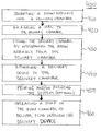
- FIG. 4 illustrates a flow chart 400 depicting an exemplary fluid delivery method.
- step 410 the step of inserting a piston assembly into a delivery chamber.
- step 420 the step of attaching a vial to a delivery chamber.
- step 430 is the step of filling the delivery chamber by withdrawing the piston assembly from the delivery chamber.
- this step is illustrated and described with regard to FIGs. 2C , and 3C .
- step 440 is the step of attaching a delivery device to the delivery chamber.
- this step is illustrated and described with regard to FIGs. 2D and 3D .
- the system may be primed or purged (step 450) as shown and described, for example, with regard to FIG. 2D .
- step 460 the step of operating a pump in the pump chamber to deliver fluid through the delivery device.
- this step is illustrated and described with regard to FIGs. 2E , and 3E .
- the pump element and components in the pump chamber may form an electrokinetic pump as described but may be reconfigured to accommodate the use of diaphragm pumps, piston pumps, and piezoelectric pumps.
- the supporting electronics 5 and electrical connectors 26 would be modified as needed according to the type of pump element and other components used.
- the movable pump element may be a piston or a diaphragm and that both may be used in a single system (i.e., as illustrated in FIG. 1A ).
- the diaphragm may be a 'rolling' type diaphragm. Rolling diaphragms have a convolute that allows predictable travel of the diaphragm. While a rolling diaphragm does have advantages, the invention is not so limited and other types of diaphragms and moveable pump elements may be used.
- a generic infusion set 96 is described and many of the pump system embodiments are represented as connected to an infusion set. While not illustrated in every embodiment, a similar configuration of an infusion set connection or other suitable delivery device can be inferred for all pump system embodiments. Alternatively, the delivery fluid 36 or drug may be dispensed without an infusion set such as, for example, when it is delivered directly into a canula or elsewhere.
- liquid and/or air seals have been illustrated in some embodiments.
- those components requiring seals have two o-ring seals while in other embodiments only one o-ring seal shown.
- Two seals are typically used in medical syringes and have thus been shown in pairs on most of the pistons described herein. It is to be appreciated that one or more o-rings may be used, however, or alternate types of seals may be employed.
- O-rings may be made from conventional sealing materials suited to medical application such as silicone and urathane, for example
- any of the configurations may be partially filled with drug or delivery fluid to any desired amount.
- the portion of pump housing i.e. delivery chambers 910, 1010) that stores the delivery fluid would be transparent and graduated to allow visibility and amount of the delivery fluid 36 present.
- a transparent housing generally would also allow visibility of any air that needs to be purged during the filling process.
- Volumetric increment markings may also be appropriately provided on the pump housing by printing, stamping, embossing, painting or otherwise indicating the contents of the delivery fluid 36 within a drug or delivery chamber. Suitable materials for construction of components include polypropylene, polycarbonate and medical grade plastics.
- One benefit of the pumping systems described herein is that these systems provide indirect pumping of delivered liquids regardless of the type of pump used for pump element 20 or pumping configuration.
- the pump components are contained within piston housing 950 or pump chamber 1020 and as the descriptions above make clear, the delivery fluid 36 does not pass through any pump mechanism and is actually separated from the pump components.
- Another advantage is the decreased likelihood of damage to fluids that are susceptible to mechanical and/or chemical degradation such as long chain protein molecules and peptides. Mechanical actions including compression, shearing, and extrusion, as well as exposure to electrical currents can cause molecular level damage to some fluids. By obviating the need for the fluids to pass through the pump mechanism, concern over pumping damage to these compounds is diminished.
- buffer refers to any suitable working fluid that may be used by a particular pumping system.
- the buffer or working fluid is any fluid having a viscosity low enough to be pumped through the pump element.
- working fluid is an electrolyte suited to the specific electrodes and dielectric material used by the electrokinetic pump.
- the electrolyte is a buffered electrolyte.
- One buffered electrolyte is a buffer made from TRIS [tris (hydroxmethyl) aminomethane] and sorbic acid at a concentration of 10 Mm and a pH of 8.3.
- TRIS-HCL, borate or sodium acetate buffers can be used.
- the buffer may also include other additives such as preservatives.
- the delivery fluid has been used throughout the description.
- the delivery fluid is any fluid having a viscosity low enough to be pumped through action of the pump element.
- the delivery fluid is a pharmacological agent.
- the delivery fluid is a therapeutic agent.
- the delivery fluid is a saline solution or Ringers solution.
Landscapes
- Engineering & Computer Science (AREA)
- Health & Medical Sciences (AREA)
- General Engineering & Computer Science (AREA)
- Mechanical Engineering (AREA)
- Hematology (AREA)
- Anesthesiology (AREA)
- Biomedical Technology (AREA)
- Heart & Thoracic Surgery (AREA)
- Physics & Mathematics (AREA)
- Life Sciences & Earth Sciences (AREA)
- Animal Behavior & Ethology (AREA)
- General Health & Medical Sciences (AREA)
- Public Health (AREA)
- Veterinary Medicine (AREA)
- Vascular Medicine (AREA)
- Fluid Mechanics (AREA)
- Infusion, Injection, And Reservoir Apparatuses (AREA)
Claims (6)
- Kolbeneinheit (970), die folgendes umfasst:ein Kolbengehäuse (950);ein weiteres Gehäuse (980) in dem Kolbengehäuse (950), welches das Kolbengehäuse in einen ersten Teil (950A) und einen zweiten Teil (950B) teilt, wobei das weitere Gehäuse Öffnungen (982) aufweist, die eine Fluidkommunikation zwischen dem ersten Teil und dem zweiten Teil vorsehen;eine erste Welle (976), welche das weitere Gehäuse (980) mit einem Kolbenboden (972) außerhalb des Kolbengehäuses (950 verbindet; undein poröses dielektrisches Material (984) innerhalb des weiteren Gehäuses (980).
- Kolbeneinheit nach Anspruch 1, wobei diese ferner eine Elektrode (924) in dem ersten Teil und eine Elektrode (924) in dem zweiten Teil umfasst, wobei die Elektroden (924) optional eine Doppelschichtkapazität von über 10-4 Mikrofarad/cm2 aufweisen.
- Kolbeneinheit nach einem der vorstehenden Ansprüche, wobei das Kolbengehäuse (950) mit einem Elektrolyt (80) gefüllt ist, und wobei sich das poröse dielektrische Material (984) innerhalb des weiteren Gehäuses in Kontakt mit dem Elektrolyt (80) befindet.
- Kolbeneinheit nach einem der vorstehenden Ansprüche, wobei diese ferner ein Dichtungselement (974; 978) um den Perimeter des Kolbenbodens (972) oder des weiteren Gehäuses (980) aufweist, wobei das Dichtungselement das weitere Gehäuse an einer Wand des Kolbengehäuses (950) abdichtet.
- Kolbeneinheit nach einem der vorstehenden Ansprüche, wobei diese ferner folgendes umfasst:einen zweiten Schaft, der das weitere Gehäuse (980) mit einem Handstück (994) außerhalb des Kolbengehäuses (950) verbindet; und optional,ein Ventil (988) in dem zweiten Schaft, wobei eine Betätigung des Ventils (988) einen Strömungspfad zwischen dem ersten Teil (950A) und dem zweiten Teil (950B) vorsieht.
- Kolbeneinheit nach Anspruch 5, wobei das Ventil (988) über ein an dem zweiten Schaft angebrachtes Handstück (994) betätigt werden kann.
Applications Claiming Priority (2)
| Application Number | Priority Date | Filing Date | Title |
|---|---|---|---|
| US73939005P | 2005-11-23 | 2005-11-23 | |
| PCT/US2006/045313 WO2007062182A2 (en) | 2005-11-23 | 2006-11-22 | Electrokinetic pump designs and drug delivery systems |
Publications (3)
| Publication Number | Publication Date |
|---|---|
| EP1957794A2 EP1957794A2 (de) | 2008-08-20 |
| EP1957794A4 EP1957794A4 (de) | 2012-07-25 |
| EP1957794B1 true EP1957794B1 (de) | 2014-07-02 |
Family
ID=38067875
Family Applications (2)
| Application Number | Title | Priority Date | Filing Date |
|---|---|---|---|
| EP20060838337 Not-in-force EP1957794B1 (de) | 2005-11-23 | 2006-11-22 | Elektrokinetische pumpenausführungen und arzneimittelabgabesysteme |
| EP20060838214 Not-in-force EP1957793B1 (de) | 2005-11-23 | 2006-11-22 | Elektrokinetische pumpenausführungen und arzneimittelabgabesysteme |
Family Applications After (1)
| Application Number | Title | Priority Date | Filing Date |
|---|---|---|---|
| EP20060838214 Not-in-force EP1957793B1 (de) | 2005-11-23 | 2006-11-22 | Elektrokinetische pumpenausführungen und arzneimittelabgabesysteme |
Country Status (4)
| Country | Link |
|---|---|
| US (5) | US20070224055A1 (de) |
| EP (2) | EP1957794B1 (de) |
| DK (1) | DK1957794T3 (de) |
| WO (2) | WO2007062182A2 (de) |
Families Citing this family (50)
| Publication number | Priority date | Publication date | Assignee | Title |
|---|---|---|---|---|
| EP1815879A3 (de) | 2001-05-18 | 2007-11-14 | Deka Products Limited Partnership | Infusionsset für eine Flüssigkeitspumpe |
| US8034026B2 (en) | 2001-05-18 | 2011-10-11 | Deka Products Limited Partnership | Infusion pump assembly |
| US7235164B2 (en) | 2002-10-18 | 2007-06-26 | Eksigent Technologies, Llc | Electrokinetic pump having capacitive electrodes |
| US8277415B2 (en) | 2006-08-23 | 2012-10-02 | Medtronic Minimed, Inc. | Infusion medium delivery device and method with drive device for driving plunger in reservoir |
| US7905868B2 (en) | 2006-08-23 | 2011-03-15 | Medtronic Minimed, Inc. | Infusion medium delivery device and method with drive device for driving plunger in reservoir |
| US8512288B2 (en) | 2006-08-23 | 2013-08-20 | Medtronic Minimed, Inc. | Infusion medium delivery device and method with drive device for driving plunger in reservoir |
| EP1957794B1 (de) | 2005-11-23 | 2014-07-02 | Eksigent Technologies, LLC | Elektrokinetische pumpenausführungen und arzneimittelabgabesysteme |
| US20080149599A1 (en) * | 2006-12-21 | 2008-06-26 | Lifescan, Inc. | Method for manufacturing an electrokinetic infusion pump |
| US7867592B2 (en) | 2007-01-30 | 2011-01-11 | Eksigent Technologies, Inc. | Methods, compositions and devices, including electroosmotic pumps, comprising coated porous surfaces |
| US8597243B2 (en) | 2007-04-30 | 2013-12-03 | Medtronic Minimed, Inc. | Systems and methods allowing for reservoir air bubble management |
| US8613725B2 (en) | 2007-04-30 | 2013-12-24 | Medtronic Minimed, Inc. | Reservoir systems and methods |
| DK2146760T3 (en) | 2007-04-30 | 2019-01-28 | Medtronic Minimed Inc | FILLING OF RESERVOIR, BUBBLE MANAGEMENT AND DELIVERY SYSTEMS FOR INFUSION MEDIA AND PROCEDURES |
| US8323250B2 (en) | 2007-04-30 | 2012-12-04 | Medtronic Minimed, Inc. | Adhesive patch systems and methods |
| US7963954B2 (en) | 2007-04-30 | 2011-06-21 | Medtronic Minimed, Inc. | Automated filling systems and methods |
| US7959715B2 (en) | 2007-04-30 | 2011-06-14 | Medtronic Minimed, Inc. | Systems and methods allowing for reservoir air bubble management |
| US8434528B2 (en) | 2007-04-30 | 2013-05-07 | Medtronic Minimed, Inc. | Systems and methods for reservoir filling |
| EP2060287B1 (de) * | 2007-11-14 | 2011-06-15 | BrainLAB AG | Medikamentenzuführungssystem für CED (Convection Enhanced Delivery)-Katheterinfusionen |
| US8251672B2 (en) * | 2007-12-11 | 2012-08-28 | Eksigent Technologies, Llc | Electrokinetic pump with fixed stroke volume |
| AU2009235064A1 (en) * | 2008-04-09 | 2009-10-15 | F.Hoffmann-La Roche Ag | Modular skin-adherable system for medical fluid delivery |
| US8262616B2 (en) * | 2008-10-10 | 2012-09-11 | Deka Products Limited Partnership | Infusion pump assembly |
| US8267892B2 (en) | 2008-10-10 | 2012-09-18 | Deka Products Limited Partnership | Multi-language / multi-processor infusion pump assembly |
| US8016789B2 (en) | 2008-10-10 | 2011-09-13 | Deka Products Limited Partnership | Pump assembly with a removable cover assembly |
| US8223028B2 (en) | 2008-10-10 | 2012-07-17 | Deka Products Limited Partnership | Occlusion detection system and method |
| US8066672B2 (en) | 2008-10-10 | 2011-11-29 | Deka Products Limited Partnership | Infusion pump assembly with a backup power supply |
| US9180245B2 (en) | 2008-10-10 | 2015-11-10 | Deka Products Limited Partnership | System and method for administering an infusible fluid |
| US8708376B2 (en) | 2008-10-10 | 2014-04-29 | Deka Products Limited Partnership | Medium connector |
| CH700630A1 (de) * | 2009-03-18 | 2010-09-30 | Tecpharma Licensing Ag | Verabreichungsvorrichtung mit hydraulischer Kraftübertragung. |
| US9060645B2 (en) * | 2010-02-02 | 2015-06-23 | Uniterra, Inc. | Beverage brewing device and method |
| EP2704759A4 (de) | 2011-05-05 | 2015-06-03 | Eksigent Technologies Llc | Gelkupplung für elektrokinetische abgabesysteme |
| US20130085462A1 (en) * | 2011-09-30 | 2013-04-04 | Kenneth Kei-ho Nip | Electrokinetic pump based wound treatment system and methods |
| KR101144500B1 (ko) * | 2012-03-16 | 2012-05-11 | 김상영 | 진공화 장치 |
| US9572928B2 (en) * | 2013-03-13 | 2017-02-21 | MRI Interventions, Inc. | Substance delivery devices, systems and methods |
| US9416777B2 (en) | 2014-09-26 | 2016-08-16 | Becton, Dickinson And Company | Control circuits for electrochemical pump with E-valves |
| CN106794301B (zh) * | 2014-11-11 | 2020-11-20 | 泰尔茂株式会社 | 药液给予装置 |
| KR101879033B1 (ko) * | 2016-03-31 | 2018-08-20 | 주식회사 포스코 | 유체량 조절장치 |
| US10960133B2 (en) | 2016-04-15 | 2021-03-30 | E-Wha Meditech Inc. | Internal pressure-adjustable liquid medicine injection apparatus |
| KR101857730B1 (ko) | 2016-11-01 | 2018-05-14 | (주)이화바이오메딕스 | 내부압력 조절이 가능한 약액주입장치 |
| KR101697980B1 (ko) * | 2016-04-15 | 2017-01-19 | (주)이화바이오메딕스 | 약액 충전 및 주입 모드에 따라 내부압력 조절이 가능한 약액주입장치 |
| US10759554B2 (en) * | 2017-02-02 | 2020-09-01 | Rai Strategic Holdings, Inc. | Dispenser unit for aerosol precursor |
| JP6851953B2 (ja) * | 2017-10-30 | 2021-03-31 | アークレイ株式会社 | ポンプ駆動方法 |
| US12023463B2 (en) * | 2018-01-02 | 2024-07-02 | Cerner Innovation, Inc. | Clinical notifications |
| KR102379943B1 (ko) * | 2018-08-20 | 2022-03-31 | 이오플로우 주식회사 | 펌프 |
| WO2020040519A1 (ko) | 2018-08-20 | 2020-02-27 | 이오플로우(주) | 전기 삼투압 펌프 |
| KR102477258B1 (ko) * | 2019-08-20 | 2022-12-14 | 이오플로우(주) | 전기 삼투압 펌프 |
| US11779699B2 (en) | 2019-09-04 | 2023-10-10 | Lynntech, Inc. | Micropump |
| WO2021124331A1 (en) * | 2019-12-18 | 2021-06-24 | E3D A.C.A.L | Transfusion pump with an insertion device |
| KR102534944B1 (ko) * | 2020-10-27 | 2023-05-30 | 이오플로우(주) | 전기 삼투압 펌프 |
| KR102619175B1 (ko) * | 2021-02-26 | 2023-12-29 | 이오플로우(주) | 펌프 |
| WO2022229660A1 (en) * | 2021-04-30 | 2022-11-03 | Neurochase Technologies Limited | Variable dose therapeutic agent dispenser |
| CN113558865B (zh) * | 2021-08-05 | 2022-08-02 | 南京市第二医院 | 一种智能控温的伤口护理绷带 |
Family Cites Families (255)
| Publication number | Priority date | Publication date | Assignee | Title |
|---|---|---|---|---|
| US1063204A (en) | 1912-07-22 | 1913-06-03 | Henry J Kraft | Aeroplane. |
| US2615940A (en) | 1949-10-25 | 1952-10-28 | Williams Milton | Electrokinetic transducing method and apparatus |
| US2661430A (en) | 1951-11-27 | 1953-12-01 | Jr Edward V Hardway | Electrokinetic measuring instrument |
| US2644900A (en) | 1951-11-27 | 1953-07-07 | Jr Edward V Hardway | Electrokinetic device |
| US2644902A (en) | 1951-11-27 | 1953-07-07 | Jr Edward V Hardway | Electrokinetic device and electrode arrangement therefor |
| US2995714A (en) | 1955-07-13 | 1961-08-08 | Kenneth W Hannah | Electrolytic oscillator |
| US2841324A (en) | 1955-12-30 | 1958-07-01 | Gen Electric | Ion vacuum pump |
| CA662714A (en) | 1958-11-28 | 1963-05-07 | Union Carbide Corporation | Electro-osmotic cell |
| CA692504A (en) | 1960-04-22 | 1964-08-11 | N. Estes Nelson | Electro-osmotic integrator |
| GB1122586A (en) | 1964-09-02 | 1968-08-07 | Mack Gordon | Electro-hydraulic transducer |
| US3298789A (en) | 1964-12-14 | 1967-01-17 | Miles Lab | Test article for the detection of glucose |
| DE1598153C3 (de) | 1966-11-22 | 1973-11-22 | Boehringer Mannheim Gmbh, 6800 Mannheim | Diagnostisches Mittel zum Nach weis der Inhaltsstoffe von Korperflus sigkeiten |
| DE1817719A1 (de) | 1968-11-16 | 1970-07-16 | Dornier System Gmbh | Diaphragma fuer elektrokinetische Geraete |
| US3544237A (en) | 1968-12-19 | 1970-12-01 | Dornier System Gmbh | Hydraulic regulating device |
| US3587227A (en) * | 1969-06-03 | 1971-06-28 | Maxwell H Weingarten | Power generating means |
| US3604417A (en) * | 1970-03-31 | 1971-09-14 | Wayne Henry Linkenheimer | Osmotic fluid reservoir for osmotically activated long-term continuous injector device |
| US3666379A (en) * | 1970-07-17 | 1972-05-30 | Pennwalt Corp | Tandem diaphragm metering pump for corrosive fluids |
| US3739573A (en) * | 1970-10-20 | 1973-06-19 | Tyco Laboratories Inc | Device for converting electrical energy to mechanical energy |
| US3682239A (en) | 1971-02-25 | 1972-08-08 | Momtaz M Abu Romia | Electrokinetic heat pipe |
| US3714528A (en) | 1972-01-13 | 1973-01-30 | Sprague Electric Co | Electrical capacitor with film-paper dielectric |
| US4043895A (en) * | 1973-05-16 | 1977-08-23 | The Dow Chemical Company | Electrophoresis apparatus |
| CA992348A (en) | 1974-03-22 | 1976-07-06 | Helen G. Tucker | Measurement of at least one of the fluid flow rate and viscous characteristics using laminar flow and viscous shear |
| US3923426A (en) | 1974-08-15 | 1975-12-02 | Alza Corp | Electroosmotic pump and fluid dispenser including same |
| DE2626348C3 (de) | 1976-06-11 | 1980-01-31 | Siemens Ag, 1000 Berlin Und 8000 Muenchen | Implantierbare Dosiereinrichtung |
| US4634431A (en) * | 1976-11-12 | 1987-01-06 | Whitney Douglass G | Syringe injector |
| US4209014A (en) * | 1977-12-12 | 1980-06-24 | Canadian Patents And Development Limited | Dispensing device for medicaments |
| JPS5921500B2 (ja) | 1978-01-28 | 1984-05-21 | 東洋紡績株式会社 | 酸素電極用酵素膜 |
| US4316233A (en) * | 1980-01-29 | 1982-02-16 | Chato John C | Single phase electrohydrodynamic pump |
| JPS5738163A (en) | 1980-08-18 | 1982-03-02 | Matsushita Electric Ind Co Ltd | Image recording method and apparatus therefor |
| US4396925A (en) | 1980-09-18 | 1983-08-02 | Matsushita Electric Industrial Co., Ltd. | Electroosmotic ink printer |
| US4402817A (en) | 1981-11-12 | 1983-09-06 | Maget Henri J R | Electrochemical prime mover |
| DE3316101C1 (de) * | 1983-05-03 | 1984-08-23 | Forschungsgesellschaft für Biomedizinische Technik, 5100 Aachen | Redundante Kolbenpumpe zum Betrieb ein- oder mehrkammriger pneumatischer Blutpumpen |
| US4639244A (en) | 1983-05-03 | 1987-01-27 | Nabil I. Rizk | Implantable electrophoretic pump for ionic drugs and associated methods |
| US4622031A (en) | 1983-08-18 | 1986-11-11 | Drug Delivery Systems Inc. | Indicator for electrophoretic transcutaneous drug delivery device |
| US4808152A (en) * | 1983-08-18 | 1989-02-28 | Drug Delivery Systems Inc. | System and method for controlling rate of electrokinetic delivery of a drug |
| US4552277A (en) * | 1984-06-04 | 1985-11-12 | Richardson Robert D | Protective shield device for use with medicine vial and the like |
| US4704324A (en) | 1985-04-03 | 1987-11-03 | The Dow Chemical Company | Semi-permeable membranes prepared via reaction of cationic groups with nucleophilic groups |
| US4886514A (en) | 1985-05-02 | 1989-12-12 | Ivac Corporation | Electrochemically driven drug dispenser |
| US4789801A (en) | 1986-03-06 | 1988-12-06 | Zenion Industries, Inc. | Electrokinetic transducing methods and apparatus and systems comprising or utilizing the same |
| US4902278A (en) * | 1987-02-18 | 1990-02-20 | Ivac Corporation | Fluid delivery micropump |
| JPH063354B2 (ja) | 1987-06-23 | 1994-01-12 | アクトロニクス株式会社 | ル−プ型細管ヒ−トパイプ |
| US4999069A (en) | 1987-10-06 | 1991-03-12 | Integrated Fluidics, Inc. | Method of bonding plastics |
| US4908112A (en) | 1988-06-16 | 1990-03-13 | E. I. Du Pont De Nemours & Co. | Silicon semiconductor wafer for analyzing micronic biological samples |
| US5004543A (en) | 1988-06-21 | 1991-04-02 | Millipore Corporation | Charge-modified hydrophobic membrane materials and method for making the same |
| US6150089A (en) | 1988-09-15 | 2000-11-21 | New York University | Method and characterizing polymer molecules or the like |
| GB2225339A (en) | 1988-11-15 | 1990-05-30 | Aligena Ag | Separating electrically charged macromolecular compounds by forced-flow membrane electrophoresis |
| US5037457A (en) | 1988-12-15 | 1991-08-06 | Millipore Corporation | Sterile hydrophobic polytetrafluoroethylene membrane laminate |
| JP2530220B2 (ja) | 1989-03-03 | 1996-09-04 | 日本特殊陶業株式会社 | 液体混合物分離装置 |
| CA2025475A1 (en) | 1989-09-27 | 1991-03-28 | Donald I. Stimpson | Hydrophilic laminated porous membranes and methods of preparing same |
| US6176962B1 (en) * | 1990-02-28 | 2001-01-23 | Aclara Biosciences, Inc. | Methods for fabricating enclosed microchannel structures |
| US6054034A (en) | 1990-02-28 | 2000-04-25 | Aclara Biosciences, Inc. | Acrylic microchannels and their use in electrophoretic applications |
| US5126022A (en) | 1990-02-28 | 1992-06-30 | Soane Tecnologies, Inc. | Method and device for moving molecules by the application of a plurality of electrical fields |
| US5770029A (en) | 1996-07-30 | 1998-06-23 | Soane Biosciences | Integrated electrophoretic microdevices |
| JPH0434468A (ja) * | 1990-05-31 | 1992-02-05 | Canon Inc | 画像形成装置 |
| US5151093A (en) * | 1990-10-29 | 1992-09-29 | Alza Corporation | Osmotically driven syringe with programmable agent delivery |
| US5219020A (en) * | 1990-11-22 | 1993-06-15 | Actronics Kabushiki Kaisha | Structure of micro-heat pipe |
| GB9027422D0 (en) * | 1990-12-18 | 1991-02-06 | Scras | Osmotically driven infusion device |
| US5137633A (en) | 1991-06-26 | 1992-08-11 | Millipore Corporation | Hydrophobic membrane having hydrophilic and charged surface and process |
| US5296115A (en) | 1991-10-04 | 1994-03-22 | Dionex Corporation | Method and apparatus for improved detection of ionic species by capillary electrophoresis |
| US5288214A (en) * | 1991-09-30 | 1994-02-22 | Toshio Fukuda | Micropump |
| US5116471A (en) * | 1991-10-04 | 1992-05-26 | Varian Associates, Inc. | System and method for improving sample concentration in capillary electrophoresis |
| US5351164A (en) | 1991-10-29 | 1994-09-27 | T.N. Frantsevich Institute For Problems In Materials Science | Electrolytic double layer capacitor |
| US5260855A (en) | 1992-01-17 | 1993-11-09 | Kaschmitter James L | Supercapacitors based on carbon foams |
| MX9305545A (es) * | 1992-09-09 | 1994-06-30 | Alza Corp | Dispositivo dispensador impulsado por fluido. |
| US5505831A (en) | 1993-01-26 | 1996-04-09 | Bio-Rad Laboratories, Inc. | Concentration of biological samples on a microliter scale and analysis by capillary electrophoresis |
| US5534328A (en) | 1993-12-02 | 1996-07-09 | E. I. Du Pont De Nemours And Company | Integrated chemical processing apparatus and processes for the preparation thereof |
| GB9309151D0 (en) * | 1993-05-04 | 1993-06-16 | Zeneca Ltd | Syringes and syringe pumps |
| US5581438A (en) | 1993-05-21 | 1996-12-03 | Halliop; Wojtek | Supercapacitor having electrodes with non-activated carbon fibers |
| DE59307434D1 (de) * | 1993-07-20 | 1997-10-30 | Sulzer Hexis Ag | Zentralsymmetrische Brennstoffzellenbatterie |
| FR2720542B1 (fr) | 1994-05-30 | 1996-07-05 | Alsthom Cge Alcatel | Procédé de fabrication d'une électrode de supercondensateur. |
| US6126723A (en) | 1994-07-29 | 2000-10-03 | Battelle Memorial Institute | Microcomponent assembly for efficient contacting of fluid |
| US6129973A (en) | 1994-07-29 | 2000-10-10 | Battelle Memorial Institute | Microchannel laminated mass exchanger and method of making |
| JPH0858897A (ja) * | 1994-08-12 | 1996-03-05 | Japan Storage Battery Co Ltd | 流体供給装置 |
| US5862035A (en) * | 1994-10-07 | 1999-01-19 | Maxwell Energy Products, Inc. | Multi-electrode double layer capacitor having single electrolyte seal and aluminum-impregnated carbon cloth electrodes |
| US5523177A (en) * | 1994-10-12 | 1996-06-04 | Giner, Inc. | Membrane-electrode assembly for a direct methanol fuel cell |
| US5571410A (en) | 1994-10-19 | 1996-11-05 | Hewlett Packard Company | Fully integrated miniaturized planar liquid sample handling and analysis device |
| US5632876A (en) * | 1995-06-06 | 1997-05-27 | David Sarnoff Research Center, Inc. | Apparatus and methods for controlling fluid flow in microchannels |
| US5683443A (en) | 1995-02-07 | 1997-11-04 | Intermedics, Inc. | Implantable stimulation electrodes with non-native metal oxide coating mixtures |
| US5573651A (en) | 1995-04-17 | 1996-11-12 | The Dow Chemical Company | Apparatus and method for flow injection analysis |
| JPH11506183A (ja) | 1995-06-06 | 1999-06-02 | デイヴィッド サーノフ リサーチ センター,インコーポレイテッド | 電気運動量輸送式ポンプ |
| US5531575A (en) | 1995-07-24 | 1996-07-02 | Lin; Gi S. | Hand pump apparatus having two pumping strokes |
| US5628890A (en) | 1995-09-27 | 1997-05-13 | Medisense, Inc. | Electrochemical sensor |
| US6045933A (en) | 1995-10-11 | 2000-04-04 | Honda Giken Kogyo Kabushiki Kaisha | Method of supplying fuel gas to a fuel cell |
| DE19602861C2 (de) | 1996-01-28 | 1997-12-11 | Meinhard Prof Dr Knoll | Probenahmesystem für in Trägerflüssigkeiten enthaltene Analyte sowie Verfahren zu seiner Herstellung |
| US5942443A (en) | 1996-06-28 | 1999-08-24 | Caliper Technologies Corporation | High throughput screening assay systems in microscale fluidic devices |
| US5885470A (en) * | 1997-04-14 | 1999-03-23 | Caliper Technologies Corporation | Controlled fluid transport in microfabricated polymeric substrates |
| NZ333345A (en) | 1996-06-28 | 2000-09-29 | Caliper Techn Corp | Electropipettor and compensation for electrophoretic bias during electroosmotic microfluid transport |
| US6429025B1 (en) | 1996-06-28 | 2002-08-06 | Caliper Technologies Corp. | High-throughput screening assay systems in microscale fluidic devices |
| GB9625491D0 (en) | 1996-12-07 | 1997-01-22 | Central Research Lab Ltd | Fluid connections |
| US5890745A (en) | 1997-01-29 | 1999-04-06 | The Board Of Trustees Of The Leland Stanford Junior University | Micromachined fluidic coupler |
| CN2286429Y (zh) | 1997-03-04 | 1998-07-22 | 中国科学技术大学 | 多孔芯柱电渗泵 |
| US5964997A (en) | 1997-03-21 | 1999-10-12 | Sarnoff Corporation | Balanced asymmetric electronic pulse patterns for operating electrode-based pumps |
| EP0867622B1 (de) | 1997-03-28 | 2004-08-04 | New Technology Management Co., Ltd. | Mikromotore, lineare Motore, Mikropumpe, Verfahren zur Anwendung derselben, Mikrobetätigungselemente, Geräte und Verfahren zur Steuerung von Flüssigkeitseigenschaften |
| AU727083B2 (en) * | 1997-04-25 | 2000-11-30 | Caliper Life Sciences, Inc. | Microfluidic devices incorporating improved channel geometries |
| US5888390A (en) | 1997-04-30 | 1999-03-30 | Hewlett-Packard Company | Multilayer integrated assembly for effecting fluid handling functions |
| US5997708A (en) | 1997-04-30 | 1999-12-07 | Hewlett-Packard Company | Multilayer integrated assembly having specialized intermediary substrate |
| AU7170298A (en) | 1997-04-30 | 1998-11-24 | Orion Research Inc. | Capillary electrophoretic separation system |
| US5961800A (en) | 1997-05-08 | 1999-10-05 | Sarnoff Corporation | Indirect electrode-based pumps |
| US6106685A (en) | 1997-05-13 | 2000-08-22 | Sarnoff Corporation | Electrode combinations for pumping fluids |
| US6156273A (en) | 1997-05-27 | 2000-12-05 | Purdue Research Corporation | Separation columns and methods for manufacturing the improved separation columns |
| US6090251A (en) * | 1997-06-06 | 2000-07-18 | Caliper Technologies, Inc. | Microfabricated structures for facilitating fluid introduction into microfluidic devices |
| US5989400A (en) | 1997-06-09 | 1999-11-23 | Hoefer Pharmacia Biotech, Inc. | Device and method for applying power to gel electrophoresis modules |
| US5942093A (en) | 1997-06-18 | 1999-08-24 | Sandia Corporation | Electro-osmotically driven liquid delivery method and apparatus |
| US6013164A (en) | 1997-06-25 | 2000-01-11 | Sandia Corporation | Electokinetic high pressure hydraulic system |
| US6019882A (en) | 1997-06-25 | 2000-02-01 | Sandia Corporation | Electrokinetic high pressure hydraulic system |
| US6277257B1 (en) | 1997-06-25 | 2001-08-21 | Sandia Corporation | Electrokinetic high pressure hydraulic system |
| NO308095B1 (no) | 1997-06-30 | 2000-07-24 | Consensus As | Fremgangsmate for transport av vaeske i tekstiler |
| MY125870A (en) * | 1997-07-25 | 2006-08-30 | Alza Corp | Osmotic delivery system flow modulator apparatus and method |
| US5989402A (en) | 1997-08-29 | 1999-11-23 | Caliper Technologies Corp. | Controller/detector interfaces for microfluidic systems |
| US6137501A (en) | 1997-09-19 | 2000-10-24 | Eastman Kodak Company | Addressing circuitry for microfluidic printing apparatus |
| US6012902A (en) | 1997-09-25 | 2000-01-11 | Caliper Technologies Corp. | Micropump |
| US6074725A (en) | 1997-12-10 | 2000-06-13 | Caliper Technologies Corp. | Fabrication of microfluidic circuits by printing techniques |
| US6068243A (en) * | 1998-01-05 | 2000-05-30 | A & B Plastics, Inc. | Self-locking, adjustable-width slat for chain link fences |
| US6158467A (en) | 1998-01-08 | 2000-12-12 | George Loo | Four-port, four-way, stopcock for intravenous injections and infusions and direction of flow of fluids and gasses |
| US6167910B1 (en) | 1998-01-20 | 2001-01-02 | Caliper Technologies Corp. | Multi-layer microfluidic devices |
| US6224728B1 (en) | 1998-04-07 | 2001-05-01 | Sandia Corporation | Valve for fluid control |
| US6274089B1 (en) | 1998-06-08 | 2001-08-14 | Caliper Technologies Corp. | Microfluidic devices, systems and methods for performing integrated reactions and separations |
| JP2004510453A (ja) | 1998-07-21 | 2004-04-08 | スペクトルクス,インコーポレイティド | 連続状分析物監視用のシステムおよび方法 |
| US6100107A (en) | 1998-08-06 | 2000-08-08 | Industrial Technology Research Institute | Microchannel-element assembly and preparation method thereof |
| ATE274749T1 (de) * | 1998-09-14 | 2004-09-15 | Asahi Glass Co Ltd | Verfahren zur herstellung eines doppelschichtkondensators mit hoher kapazität |
| US6444150B1 (en) | 1998-09-25 | 2002-09-03 | Sandia Corporation | Method of filling a microchannel separation column |
| SE518114C2 (sv) | 1998-09-28 | 2002-08-27 | Asept Int Ab | Pumpanordning för att pumpa flytande livsmedel |
| US6086243A (en) | 1998-10-01 | 2000-07-11 | Sandia Corporation | Electrokinetic micro-fluid mixer |
| US6605472B1 (en) | 1998-10-09 | 2003-08-12 | The Governors Of The University Of Alberta | Microfluidic devices connected to glass capillaries with minimal dead volume |
| US6068767A (en) * | 1998-10-29 | 2000-05-30 | Sandia Corporation | Device to improve detection in electro-chromatography |
| US6572823B1 (en) | 1998-12-09 | 2003-06-03 | Bristol-Myers Squibb Pharma Company | Apparatus and method for reconstituting a solution |
| US6319476B1 (en) | 1999-03-02 | 2001-11-20 | Perseptive Biosystems, Inc. | Microfluidic connector |
| US6477410B1 (en) | 2000-05-31 | 2002-11-05 | Biophoretic Therapeutic Systems, Llc | Electrokinetic delivery of medicaments |
| US6541021B1 (en) * | 1999-03-18 | 2003-04-01 | Durect Corporation | Devices and methods for pain management |
| US6349740B1 (en) * | 1999-04-08 | 2002-02-26 | Abbott Laboratories | Monolithic high performance miniature flow control unit |
| US6846399B2 (en) | 1999-05-12 | 2005-01-25 | Sandia National Laboratories | Castable three-dimensional stationary phase for electric field-driven applications |
| JP4539898B2 (ja) | 1999-05-17 | 2010-09-08 | フラウンホッファー−ゲゼルシャフト ツァ フェルダールング デァ アンゲヴァンテン フォアシュンク エー.ファオ | マイクロメカニック・ポンプ |
| US6406605B1 (en) | 1999-06-01 | 2002-06-18 | Ysi Incorporated | Electroosmotic flow controlled microfluidic devices |
| US6255551B1 (en) | 1999-06-04 | 2001-07-03 | General Electric Company | Method and system for treating contaminated media |
| US6287440B1 (en) | 1999-06-18 | 2001-09-11 | Sandia Corporation | Method for eliminating gas blocking in electrokinetic pumping systems |
| US6495015B1 (en) | 1999-06-18 | 2002-12-17 | Sandia National Corporation | Electrokinetically pumped high pressure sprays |
| GB2385014B (en) | 1999-06-21 | 2003-10-15 | Micro Chemical Systems Ltd | Method of preparing a working solution |
| US6899137B2 (en) | 1999-06-28 | 2005-05-31 | California Institute Of Technology | Microfabricated elastomeric valve and pump systems |
| US7244402B2 (en) | 2001-04-06 | 2007-07-17 | California Institute Of Technology | Microfluidic protein crystallography |
| US7195670B2 (en) * | 2000-06-27 | 2007-03-27 | California Institute Of Technology | High throughput screening of crystallization of materials |
| US6613211B1 (en) | 1999-08-27 | 2003-09-02 | Aclara Biosciences, Inc. | Capillary electrokinesis based cellular assays |
| US6179586B1 (en) * | 1999-09-15 | 2001-01-30 | Honeywell International Inc. | Dual diaphragm, single chamber mesopump |
| US6210986B1 (en) * | 1999-09-23 | 2001-04-03 | Sandia Corporation | Microfluidic channel fabrication method |
| JP2003527972A (ja) | 1999-10-04 | 2003-09-24 | ナノストリーム・インコーポレイテッド | 挟まれたステンシルを含むモジュラー型マイクロ流体デバイス |
| US6497680B1 (en) | 1999-12-17 | 2002-12-24 | Abbott Laboratories | Method for compensating for pressure differences across valves in cassette type IV pump |
| US6620625B2 (en) | 2000-01-06 | 2003-09-16 | Caliper Technologies Corp. | Ultra high throughput sampling and analysis systems and methods |
| DE10001172A1 (de) | 2000-01-13 | 2001-07-26 | Max Planck Gesellschaft | Templatieren von Feststoffpartikeln mit Polymermultischichten |
| CN1261755C (zh) | 2000-02-23 | 2006-06-28 | 卡钳技术有限公司 | 多容器压力控制系统 |
| US6824900B2 (en) | 2002-03-04 | 2004-11-30 | Mti Microfuel Cells Inc. | Method and apparatus for water management of a fuel cell system |
| US7141152B2 (en) | 2000-03-16 | 2006-11-28 | Le Febre David A | Analyte species separation system |
| US6358387B1 (en) * | 2000-03-27 | 2002-03-19 | Caliper Technologies Corporation | Ultra high throughput microfluidic analytical systems and methods |
| US6290909B1 (en) | 2000-04-13 | 2001-09-18 | Sandia Corporation | Sample injector for high pressure liquid chromatography |
| US6460420B1 (en) | 2000-04-13 | 2002-10-08 | Sandia National Laboratories | Flowmeter for pressure-driven chromatography systems |
| US6561208B1 (en) | 2000-04-14 | 2003-05-13 | Nanostream, Inc. | Fluidic impedances in microfluidic system |
| GB0011575D0 (en) | 2000-05-12 | 2000-07-05 | Central Research Lab Ltd | An adaptor for receiving a fluidic device |
| US7351376B1 (en) | 2000-06-05 | 2008-04-01 | California Institute Of Technology | Integrated active flux microfluidic devices and methods |
| US6472443B1 (en) | 2000-06-22 | 2002-10-29 | Sandia National Laboratories | Porous polymer media |
| FR2811403B1 (fr) | 2000-07-05 | 2002-08-16 | Commissariat Energie Atomique | Raccordement d'un micro-tube a une structure |
| AU2001277075A1 (en) | 2000-07-21 | 2002-02-05 | Aclara Biosciences, Inc. | Method and devices for capillary electrophoresis with a norbornene based surface coating |
| EP1309404A2 (de) | 2000-08-07 | 2003-05-14 | Nanostream, Inc. | Mischvorrichtung in einem mikrofluidischen system |
| IL137796A0 (en) | 2000-08-10 | 2001-10-31 | Elestor Ltd | All-solid-state polymer electrochemical capacitors |
| DE10040084A1 (de) | 2000-08-16 | 2002-03-07 | Siemens Ag | Verfahren zur Mischung von Brennstoff in Wasser, zugehörige Vorrichtung und Verwendung dieser Vorrichtung |
| EP1335764B1 (de) * | 2000-09-08 | 2007-06-06 | Insulet Corporation | Infusionsvorrichtung und System |
| US20020048425A1 (en) | 2000-09-20 | 2002-04-25 | Sarnoff Corporation | Microfluidic optical electrohydrodynamic switch |
| US6952962B2 (en) | 2000-10-24 | 2005-10-11 | Sandia National Laboratories | Mobile monolithic polymer elements for flow control in microfluidic devices |
| US6770182B1 (en) | 2000-11-14 | 2004-08-03 | Sandia National Laboratories | Method for producing a thin sample band in a microchannel device |
| US6409698B1 (en) | 2000-11-27 | 2002-06-25 | John N. Robinson | Perforate electrodiffusion pump |
| US6439367B1 (en) | 2000-12-01 | 2002-08-27 | Lockhead Martin Corporation | Bowl diverter |
| US6805783B2 (en) | 2000-12-13 | 2004-10-19 | Toyo Technologies, Inc. | Method for manipulating a solution using a ferroelectric electro-osmotic pump |
| US6497975B2 (en) | 2000-12-15 | 2002-12-24 | Motorola, Inc. | Direct methanol fuel cell including integrated flow field and method of fabrication |
| US6733244B1 (en) * | 2000-12-20 | 2004-05-11 | University Of Arkansas, N.A. | Microfluidics and small volume mixing based on redox magnetohydrodynamics methods |
| US7070681B2 (en) | 2001-01-24 | 2006-07-04 | The Board Of Trustees Of The Leland Stanford Junior University | Electrokinetic instability micromixer |
| WO2002070118A2 (en) | 2001-02-09 | 2002-09-12 | Microchem Solutions | Apparatus and method for small-volume fluid manipulation and transportation |
| DE10108570C2 (de) | 2001-02-22 | 2003-05-28 | Laeis & Bucher Gmbh | Verfahren und Vorrichtung zum Herstellen eines Formkörpers |
| WO2002069016A2 (en) | 2001-02-28 | 2002-09-06 | Lightwave Microsystems Corporation | Microfluid control for waveguide optical switches, variable attenuators, and other optical devices |
| FR2821657B1 (fr) | 2001-03-01 | 2003-09-26 | Commissariat Energie Atomique | Dispositif pour la connexion etanche et reversible de capillaires a un composant de micro-fluidique |
| US6706163B2 (en) | 2001-03-21 | 2004-03-16 | Michael Seul | On-chip analysis of particles and fractionation of particle mixtures using light-controlled electrokinetic assembly of particles near surfaces |
| US6418968B1 (en) | 2001-04-20 | 2002-07-16 | Nanostream, Inc. | Porous microfluidic valves |
| US6878473B2 (en) * | 2001-05-02 | 2005-04-12 | Kabushiki Kaisha Toshiba | Fuel cell power generating apparatus, and operating method and combined battery of fuel cell power generating apparatus |
| US6880576B2 (en) | 2001-06-07 | 2005-04-19 | Nanostream, Inc. | Microfluidic devices for methods development |
| US6919046B2 (en) | 2001-06-07 | 2005-07-19 | Nanostream, Inc. | Microfluidic analytical devices and methods |
| US20020187557A1 (en) | 2001-06-07 | 2002-12-12 | Hobbs Steven E. | Systems and methods for introducing samples into microfluidic devices |
| US6729352B2 (en) * | 2001-06-07 | 2004-05-04 | Nanostream, Inc. | Microfluidic synthesis devices and methods |
| US20020189947A1 (en) | 2001-06-13 | 2002-12-19 | Eksigent Technologies Llp | Electroosmotic flow controller |
| US7465382B2 (en) * | 2001-06-13 | 2008-12-16 | Eksigent Technologies Llc | Precision flow control system |
| TW588076B (en) * | 2001-07-03 | 2004-05-21 | Sumitomo Chemical Co | Polymer electrolyte membrane and fuel cell |
| US6766817B2 (en) | 2001-07-25 | 2004-07-27 | Tubarc Technologies, Llc | Fluid conduction utilizing a reversible unsaturated siphon with tubarc porosity action |
| US6770183B1 (en) | 2001-07-26 | 2004-08-03 | Sandia National Laboratories | Electrokinetic pump |
| US7456025B2 (en) | 2001-08-28 | 2008-11-25 | Porex Corporation | Sintered polymer membrane for analyte detection device |
| US6529377B1 (en) | 2001-09-05 | 2003-03-04 | Microelectronic & Computer Technology Corporation | Integrated cooling system |
| US6942018B2 (en) | 2001-09-28 | 2005-09-13 | The Board Of Trustees Of The Leland Stanford Junior University | Electroosmotic microchannel cooling system |
| DE60218713T2 (de) | 2001-10-02 | 2007-11-08 | Sophion Bioscience A/S | Siebpumpe zur erzeugung eines elektroosmotischen flusses |
| US7037082B2 (en) | 2001-10-02 | 2006-05-02 | Sophion Bioscience A/S | Corbino disc electroosmotic flow pump |
| US6619925B2 (en) | 2001-10-05 | 2003-09-16 | Toyo Technologies, Inc. | Fiber filled electro-osmotic pump |
| US6739576B2 (en) | 2001-12-20 | 2004-05-25 | Nanostream, Inc. | Microfluidic flow control device with floating element |
| AU2003228205A1 (en) | 2002-01-18 | 2003-09-02 | The Regents Of The University Of Michigan | Porous polymers: compositions and uses thereof |
| US6719535B2 (en) * | 2002-01-31 | 2004-04-13 | Eksigent Technologies, Llc | Variable potential electrokinetic device |
| US6814859B2 (en) | 2002-02-13 | 2004-11-09 | Nanostream, Inc. | Frit material and bonding method for microfluidic separation devices |
| US6685442B2 (en) * | 2002-02-20 | 2004-02-03 | Sandia National Laboratories | Actuator device utilizing a conductive polymer gel |
| WO2003072254A1 (en) | 2002-02-22 | 2003-09-04 | Nanostream, Inc. | Ratiometric dilution devices and methods |
| JP3637392B2 (ja) | 2002-04-08 | 2005-04-13 | 独立行政法人産業技術総合研究所 | 燃料電池 |
| US7470267B2 (en) * | 2002-05-01 | 2008-12-30 | Microlin, Llc | Fluid delivery device having an electrochemical pump with an anionic exchange membrane and associated method |
| US7060170B2 (en) | 2002-05-01 | 2006-06-13 | Eksigent Technologies Llc | Bridges, elements and junctions for electroosmotic flow systems |
| US7101947B2 (en) | 2002-06-14 | 2006-09-05 | Florida State University Research Foundation, Inc. | Polyelectrolyte complex films for analytical and membrane separation of chiral compounds |
| NO20023398D0 (no) | 2002-07-15 | 2002-07-15 | Osmotex As | Anordning og fremgangsmåte for transport av v¶ske gjennom materialer |
| US7235164B2 (en) | 2002-10-18 | 2007-06-26 | Eksigent Technologies, Llc | Electrokinetic pump having capacitive electrodes |
| US7517440B2 (en) * | 2002-07-17 | 2009-04-14 | Eksigent Technologies Llc | Electrokinetic delivery systems, devices and methods |
| US7364647B2 (en) | 2002-07-17 | 2008-04-29 | Eksigent Technologies Llc | Laminated flow device |
| AU2003270882A1 (en) * | 2002-09-23 | 2004-05-04 | Cooligy, Inc. | Micro-fabricated electrokinetic pump with on-frit electrode |
| US7419822B2 (en) | 2002-10-04 | 2008-09-02 | Noo Li Jeon | Microfluidic device for enabling fluidic isolation among interconnected compartments within the apparatus and methods relating to same |
| US6994151B2 (en) | 2002-10-22 | 2006-02-07 | Cooligy, Inc. | Vapor escape microchannel heat exchanger |
| US7390457B2 (en) | 2002-10-31 | 2008-06-24 | Agilent Technologies, Inc. | Integrated microfluidic array device |
| US7010964B2 (en) | 2002-10-31 | 2006-03-14 | Nanostream, Inc. | Pressurized microfluidic devices with optical detection regions |
| US6843272B2 (en) * | 2002-11-25 | 2005-01-18 | Sandia National Laboratories | Conductance valve and pressure-to-conductance transducer method and apparatus |
| US20040107996A1 (en) * | 2002-12-09 | 2004-06-10 | Crocker Robert W. | Variable flow control apparatus |
| AU2003294602A1 (en) | 2002-12-13 | 2004-07-09 | Aclara Biosciences, Inc. | Closed-loop control of electrokinetic processes in microfludic devices based on optical readings |
| US6832787B1 (en) | 2003-01-24 | 2004-12-21 | Sandia National Laboratories | Edge compression manifold apparatus |
| US7371229B2 (en) * | 2003-01-28 | 2008-05-13 | Felix Theeuwes | Dual electrode advanced electrochemical delivery system |
| US6872292B2 (en) * | 2003-01-28 | 2005-03-29 | Microlin, L.C. | Voltage modulation of advanced electrochemical delivery system |
| US7147955B2 (en) | 2003-01-31 | 2006-12-12 | Societe Bic | Fuel cartridge for fuel cells |
| US20050014134A1 (en) * | 2003-03-06 | 2005-01-20 | West Jason Andrew Appleton | Viral identification by generation and detection of protein signatures |
| CA2520610A1 (en) * | 2003-03-31 | 2004-10-21 | Alza Corporation | Osmotic pump with means for dissipating internal pressure |
| US7050660B2 (en) | 2003-04-07 | 2006-05-23 | Eksigent Technologies Llc | Microfluidic detection device having reduced dispersion and method for making same |
| US6962658B2 (en) | 2003-05-20 | 2005-11-08 | Eksigent Technologies, Llc | Variable flow rate injector |
| US7316543B2 (en) | 2003-05-30 | 2008-01-08 | The Board Of Trustees Of The Leland Stanford Junior University | Electroosmotic micropump with planar features |
| US7258777B2 (en) | 2003-07-21 | 2007-08-21 | Eksigent Technologies Llc | Bridges for electroosmotic flow systems |
| US7231839B2 (en) | 2003-08-11 | 2007-06-19 | The Board Of Trustees Of The Leland Stanford Junior University | Electroosmotic micropumps with applications to fluid dispensing and field sampling |
| US7217351B2 (en) * | 2003-08-29 | 2007-05-15 | Beta Micropump Partners Llc | Valve for controlling flow of a fluid |
| FR2859895B1 (fr) * | 2003-09-18 | 2006-09-29 | Pascale Pittet | Dispositif pour la preparation de rations alimentaires equilibrees et a valeur energetique controlee |
| KR20060105787A (ko) | 2003-11-21 | 2006-10-11 | 가부시키가이샤 에바라 세이사꾸쇼 | 액체를 이용한 마이크로칩 장치 |
| EP1535952B1 (de) | 2003-11-28 | 2013-01-16 | Universite Louis Pasteur | Verfahren zur Herstellung vernetzter, mehrlagiger Polyelektrolytfilme |
| WO2005097667A2 (en) | 2004-04-02 | 2005-10-20 | Eksigent Technologies Llc | Microfluidic device |
| US7521140B2 (en) | 2004-04-19 | 2009-04-21 | Eksigent Technologies, Llc | Fuel cell system with electrokinetic pump |
| US7559356B2 (en) | 2004-04-19 | 2009-07-14 | Eksident Technologies, Inc. | Electrokinetic pump driven heat transfer system |
| JP4897680B2 (ja) * | 2004-07-20 | 2012-03-14 | エージェンシー フォー サイエンス, テクノロジー アンド リサーチ | 可変焦点マイクロレンズ |
| US8187441B2 (en) * | 2004-10-19 | 2012-05-29 | Evans Christine E | Electrochemical pump |
| US7213473B2 (en) | 2004-12-15 | 2007-05-08 | Sandia National Laboratories | Sample preparation system for microfluidic applications |
| US7429317B2 (en) | 2004-12-20 | 2008-09-30 | Eksigent Technologies Llc | Electrokinetic device employing a non-newtonian liquid |
| KR100707191B1 (ko) | 2005-05-25 | 2007-04-13 | 삼성전자주식회사 | 전기투석을 이용한 염 농도 조절 장치, 그를 포함하는랩온어칩 및 그를 이용한 염 농도 조절 방법 |
| US20070062251A1 (en) * | 2005-09-19 | 2007-03-22 | Lifescan, Inc. | Infusion Pump With Closed Loop Control and Algorithm |
| US20070093753A1 (en) * | 2005-09-19 | 2007-04-26 | Lifescan, Inc. | Malfunction Detection Via Pressure Pulsation |
| US20070066940A1 (en) * | 2005-09-19 | 2007-03-22 | Lifescan, Inc. | Systems and Methods for Detecting a Partition Position in an Infusion Pump |
| EP1957794B1 (de) | 2005-11-23 | 2014-07-02 | Eksigent Technologies, LLC | Elektrokinetische pumpenausführungen und arzneimittelabgabesysteme |
| WO2007079116A1 (en) * | 2005-12-28 | 2007-07-12 | Tti Ellebeau, Inc. | Electroosmotic pump apparatus and method to deliver active agents to biological interfaces |
| WO2007077255A2 (en) * | 2006-01-06 | 2007-07-12 | Novo Nordisk A/S | A medication delivery device applying a collapsible reservoir |
| US8211054B2 (en) | 2006-05-01 | 2012-07-03 | Carefusion 303, Inc. | System and method for controlling administration of medical fluid |
| WO2008055256A2 (en) * | 2006-11-02 | 2008-05-08 | The Regents Of The University Of California | Method and apparatus for real-time feedback control of electrical manipulation of droplets on chip |
| US7867592B2 (en) | 2007-01-30 | 2011-01-11 | Eksigent Technologies, Inc. | Methods, compositions and devices, including electroosmotic pumps, comprising coated porous surfaces |
| US20090096266A1 (en) * | 2007-10-11 | 2009-04-16 | Chun-Chang Tai | Seat frame assembly |
| US8251672B2 (en) | 2007-12-11 | 2012-08-28 | Eksigent Technologies, Llc | Electrokinetic pump with fixed stroke volume |
| US20120282111A1 (en) | 2011-05-05 | 2012-11-08 | Nip Kenneth Kei-Ho | System and method of differential pressure control of a reciprocating electrokinetic pump |
| EP2704759A4 (de) | 2011-05-05 | 2015-06-03 | Eksigent Technologies Llc | Gelkupplung für elektrokinetische abgabesysteme |
| WO2012151588A1 (en) | 2011-05-05 | 2012-11-08 | Eksigent Technologies, Llc | Ganging electrokinetic pumps |
| US20130085462A1 (en) * | 2011-09-30 | 2013-04-04 | Kenneth Kei-ho Nip | Electrokinetic pump based wound treatment system and methods |
| US11286705B1 (en) | 2020-10-27 | 2022-03-29 | Hi-Lex Controls, Inc. | Cable guide assembly for a window regulator |
-
2006
- 2006-11-22 EP EP20060838337 patent/EP1957794B1/de not_active Not-in-force
- 2006-11-22 US US11/603,926 patent/US20070224055A1/en not_active Abandoned
- 2006-11-22 WO PCT/US2006/045313 patent/WO2007062182A2/en not_active Ceased
- 2006-11-22 US US11/603,925 patent/US8794929B2/en not_active Expired - Fee Related
- 2006-11-22 DK DK06838337T patent/DK1957794T3/da active
- 2006-11-22 WO PCT/US2006/045112 patent/WO2007062068A2/en not_active Ceased
- 2006-11-22 US US12/094,956 patent/US8152477B2/en not_active Expired - Fee Related
- 2006-11-22 EP EP20060838214 patent/EP1957793B1/de not_active Not-in-force
-
2010
- 2010-03-22 US US12/728,844 patent/US20110031268A1/en not_active Abandoned
-
2013
- 2013-02-11 US US13/764,568 patent/US20130156608A1/en not_active Abandoned
Also Published As
| Publication number | Publication date |
|---|---|
| US20130156608A1 (en) | 2013-06-20 |
| EP1957793A4 (de) | 2011-04-13 |
| WO2007062068A3 (en) | 2009-05-07 |
| US8152477B2 (en) | 2012-04-10 |
| EP1957794A2 (de) | 2008-08-20 |
| WO2007062182A2 (en) | 2007-05-31 |
| WO2007062068A2 (en) | 2007-05-31 |
| US8794929B2 (en) | 2014-08-05 |
| WO2007062182A3 (en) | 2007-11-08 |
| US20070224055A1 (en) | 2007-09-27 |
| DK1957794T3 (da) | 2014-08-11 |
| US20090185916A1 (en) | 2009-07-23 |
| US20110031268A1 (en) | 2011-02-10 |
| EP1957793A2 (de) | 2008-08-20 |
| US20070148014A1 (en) | 2007-06-28 |
| EP1957793B1 (de) | 2013-01-16 |
| EP1957794A4 (de) | 2012-07-25 |
Similar Documents
| Publication | Publication Date | Title |
|---|---|---|
| EP1957794B1 (de) | Elektrokinetische pumpenausführungen und arzneimittelabgabesysteme | |
| RU2755697C2 (ru) | Инициализация амбулаторной инфузионной системы | |
| US5243982A (en) | Device for determining the concentration of at least one substance in organic tissue | |
| CN109715233B (zh) | 电渗透泵 | |
| US7789853B2 (en) | Infusion apparatus with constant force spring energy source | |
| EP2060286B1 (de) | Osmotische Pumpe | |
| US20150258273A1 (en) | Electrochemically-Actuated Microfluidic Devices | |
| EP1865199A1 (de) | Flüssigkeitstransportvorrichtung und -system | |
| CN1589164A (zh) | 医药用的泵装置 | |
| EP2146760A2 (de) | Reservoir-füllung, blasenkontrolle und infusionsmedium-abgabesysteme und verfahren dafür | |
| GB2065789A (en) | Pump including a repplaceable pump cassette | |
| EP1904123A2 (de) | Elektro-osmotische flüssigkeitsausgabevorrichtung mit doppelmembran | |
| CN101365505A (zh) | 使用收缩式储存器的药物输送设备 | |
| US8251672B2 (en) | Electrokinetic pump with fixed stroke volume | |
| JP6652317B2 (ja) | 液体供給装置 | |
| DE60225045T2 (de) | Tragbares medizinisches abgabesystem und dazugehörige einsatzeinheit, wobei der druck im behälter mittels einer gepumpten flüssigkeit erzeugt wird | |
| US11324663B2 (en) | Method and apparatus for transferring a liquid drug to a collapsible reservoir | |
| US20230014094A1 (en) | Space-efficient free piston reservoir for a wearable drug delivery device | |
| CN114441236A (zh) | 一种采样装置以及样本分析仪 | |
| EP4684814A1 (de) | Ventil für eine medizinische flüssigkeitsdosiervorrichtung |
Legal Events
| Date | Code | Title | Description |
|---|---|---|---|
| PUAI | Public reference made under article 153(3) epc to a published international application that has entered the european phase |
Free format text: ORIGINAL CODE: 0009012 |
|
| 17P | Request for examination filed |
Effective date: 20080623 |
|
| AK | Designated contracting states |
Kind code of ref document: A2 Designated state(s): AT BE BG CH CY CZ DE DK EE ES FI FR GB GR HU IE IS IT LI LT LU LV MC NL PL PT RO SE SI SK TR |
|
| RAP1 | Party data changed (applicant data changed or rights of an application transferred) |
Owner name: EKSIGENT TECHNOLOGIES, LLC |
|
| A4 | Supplementary search report drawn up and despatched |
Effective date: 20120627 |
|
| RIC1 | Information provided on ipc code assigned before grant |
Ipc: F04B 37/02 20060101AFI20120621BHEP Ipc: F04B 19/00 20060101ALI20120621BHEP Ipc: A61M 5/142 20060101ALI20120621BHEP Ipc: F04B 9/08 20060101ALI20120621BHEP |
|
| DAX | Request for extension of the european patent (deleted) | ||
| 17Q | First examination report despatched |
Effective date: 20130221 |
|
| GRAP | Despatch of communication of intention to grant a patent |
Free format text: ORIGINAL CODE: EPIDOSNIGR1 |
|
| INTG | Intention to grant announced |
Effective date: 20140123 |
|
| GRAS | Grant fee paid |
Free format text: ORIGINAL CODE: EPIDOSNIGR3 |
|
| GRAA | (expected) grant |
Free format text: ORIGINAL CODE: 0009210 |
|
| AK | Designated contracting states |
Kind code of ref document: B1 Designated state(s): AT BE BG CH CY CZ DE DK EE ES FI FR GB GR HU IE IS IT LI LT LU LV MC NL PL PT RO SE SI SK TR |
|
| REG | Reference to a national code |
Ref country code: GB Ref legal event code: FG4D |
|
| REG | Reference to a national code |
Ref country code: AT Ref legal event code: REF Ref document number: 676080 Country of ref document: AT Kind code of ref document: T Effective date: 20140715 Ref country code: CH Ref legal event code: EP |
|
| REG | Reference to a national code |
Ref country code: IE Ref legal event code: FG4D |
|
| REG | Reference to a national code |
Ref country code: DK Ref legal event code: T3 Effective date: 20140804 |
|
| REG | Reference to a national code |
Ref country code: DE Ref legal event code: R096 Ref document number: 602006042168 Country of ref document: DE Effective date: 20140814 |
|
| REG | Reference to a national code |
Ref country code: CH Ref legal event code: NV Representative=s name: MEYER AND KOLLEGEN, CH |
|
| REG | Reference to a national code |
Ref country code: AT Ref legal event code: MK05 Ref document number: 676080 Country of ref document: AT Kind code of ref document: T Effective date: 20140702 |
|
| REG | Reference to a national code |
Ref country code: NL Ref legal event code: VDEP Effective date: 20140702 |
|
| REG | Reference to a national code |
Ref country code: LT Ref legal event code: MG4D |
|
| PGFP | Annual fee paid to national office [announced via postgrant information from national office to epo] |
Ref country code: DK Payment date: 20141111 Year of fee payment: 9 |
|
| PG25 | Lapsed in a contracting state [announced via postgrant information from national office to epo] |
Ref country code: BG Free format text: LAPSE BECAUSE OF FAILURE TO SUBMIT A TRANSLATION OF THE DESCRIPTION OR TO PAY THE FEE WITHIN THE PRESCRIBED TIME-LIMIT Effective date: 20141002 Ref country code: CZ Free format text: LAPSE BECAUSE OF FAILURE TO SUBMIT A TRANSLATION OF THE DESCRIPTION OR TO PAY THE FEE WITHIN THE PRESCRIBED TIME-LIMIT Effective date: 20140702 Ref country code: SE Free format text: LAPSE BECAUSE OF FAILURE TO SUBMIT A TRANSLATION OF THE DESCRIPTION OR TO PAY THE FEE WITHIN THE PRESCRIBED TIME-LIMIT Effective date: 20140702 Ref country code: PT Free format text: LAPSE BECAUSE OF FAILURE TO SUBMIT A TRANSLATION OF THE DESCRIPTION OR TO PAY THE FEE WITHIN THE PRESCRIBED TIME-LIMIT Effective date: 20141103 Ref country code: FI Free format text: LAPSE BECAUSE OF FAILURE TO SUBMIT A TRANSLATION OF THE DESCRIPTION OR TO PAY THE FEE WITHIN THE PRESCRIBED TIME-LIMIT Effective date: 20140702 Ref country code: GR Free format text: LAPSE BECAUSE OF FAILURE TO SUBMIT A TRANSLATION OF THE DESCRIPTION OR TO PAY THE FEE WITHIN THE PRESCRIBED TIME-LIMIT Effective date: 20141003 Ref country code: LT Free format text: LAPSE BECAUSE OF FAILURE TO SUBMIT A TRANSLATION OF THE DESCRIPTION OR TO PAY THE FEE WITHIN THE PRESCRIBED TIME-LIMIT Effective date: 20140702 Ref country code: ES Free format text: LAPSE BECAUSE OF FAILURE TO SUBMIT A TRANSLATION OF THE DESCRIPTION OR TO PAY THE FEE WITHIN THE PRESCRIBED TIME-LIMIT Effective date: 20140702 |
|
| PGFP | Annual fee paid to national office [announced via postgrant information from national office to epo] |
Ref country code: FR Payment date: 20141110 Year of fee payment: 9 Ref country code: CH Payment date: 20141112 Year of fee payment: 9 Ref country code: DE Payment date: 20141118 Year of fee payment: 9 Ref country code: GB Payment date: 20141119 Year of fee payment: 9 |
|
| PG25 | Lapsed in a contracting state [announced via postgrant information from national office to epo] |
Ref country code: AT Free format text: LAPSE BECAUSE OF FAILURE TO SUBMIT A TRANSLATION OF THE DESCRIPTION OR TO PAY THE FEE WITHIN THE PRESCRIBED TIME-LIMIT Effective date: 20140702 Ref country code: PL Free format text: LAPSE BECAUSE OF FAILURE TO SUBMIT A TRANSLATION OF THE DESCRIPTION OR TO PAY THE FEE WITHIN THE PRESCRIBED TIME-LIMIT Effective date: 20140702 Ref country code: CY Free format text: LAPSE BECAUSE OF FAILURE TO SUBMIT A TRANSLATION OF THE DESCRIPTION OR TO PAY THE FEE WITHIN THE PRESCRIBED TIME-LIMIT Effective date: 20140702 Ref country code: NL Free format text: LAPSE BECAUSE OF FAILURE TO SUBMIT A TRANSLATION OF THE DESCRIPTION OR TO PAY THE FEE WITHIN THE PRESCRIBED TIME-LIMIT Effective date: 20140702 Ref country code: IS Free format text: LAPSE BECAUSE OF FAILURE TO SUBMIT A TRANSLATION OF THE DESCRIPTION OR TO PAY THE FEE WITHIN THE PRESCRIBED TIME-LIMIT Effective date: 20141102 Ref country code: LV Free format text: LAPSE BECAUSE OF FAILURE TO SUBMIT A TRANSLATION OF THE DESCRIPTION OR TO PAY THE FEE WITHIN THE PRESCRIBED TIME-LIMIT Effective date: 20140702 |
|
| REG | Reference to a national code |
Ref country code: DE Ref legal event code: R097 Ref document number: 602006042168 Country of ref document: DE |
|
| PG25 | Lapsed in a contracting state [announced via postgrant information from national office to epo] |
Ref country code: RO Free format text: LAPSE BECAUSE OF FAILURE TO SUBMIT A TRANSLATION OF THE DESCRIPTION OR TO PAY THE FEE WITHIN THE PRESCRIBED TIME-LIMIT Effective date: 20140702 Ref country code: EE Free format text: LAPSE BECAUSE OF FAILURE TO SUBMIT A TRANSLATION OF THE DESCRIPTION OR TO PAY THE FEE WITHIN THE PRESCRIBED TIME-LIMIT Effective date: 20140702 Ref country code: SK Free format text: LAPSE BECAUSE OF FAILURE TO SUBMIT A TRANSLATION OF THE DESCRIPTION OR TO PAY THE FEE WITHIN THE PRESCRIBED TIME-LIMIT Effective date: 20140702 Ref country code: IT Free format text: LAPSE BECAUSE OF FAILURE TO SUBMIT A TRANSLATION OF THE DESCRIPTION OR TO PAY THE FEE WITHIN THE PRESCRIBED TIME-LIMIT Effective date: 20140702 |
|
| PLBE | No opposition filed within time limit |
Free format text: ORIGINAL CODE: 0009261 |
|
| STAA | Information on the status of an ep patent application or granted ep patent |
Free format text: STATUS: NO OPPOSITION FILED WITHIN TIME LIMIT |
|
| 26N | No opposition filed |
Effective date: 20150407 |
|
| PG25 | Lapsed in a contracting state [announced via postgrant information from national office to epo] |
Ref country code: BE Free format text: LAPSE BECAUSE OF NON-PAYMENT OF DUE FEES Effective date: 20141130 Ref country code: MC Free format text: LAPSE BECAUSE OF FAILURE TO SUBMIT A TRANSLATION OF THE DESCRIPTION OR TO PAY THE FEE WITHIN THE PRESCRIBED TIME-LIMIT Effective date: 20140702 Ref country code: LU Free format text: LAPSE BECAUSE OF FAILURE TO SUBMIT A TRANSLATION OF THE DESCRIPTION OR TO PAY THE FEE WITHIN THE PRESCRIBED TIME-LIMIT Effective date: 20141122 |
|
| REG | Reference to a national code |
Ref country code: IE Ref legal event code: MM4A |
|
| PG25 | Lapsed in a contracting state [announced via postgrant information from national office to epo] |
Ref country code: IE Free format text: LAPSE BECAUSE OF NON-PAYMENT OF DUE FEES Effective date: 20141122 |
|
| PG25 | Lapsed in a contracting state [announced via postgrant information from national office to epo] |
Ref country code: SI Free format text: LAPSE BECAUSE OF FAILURE TO SUBMIT A TRANSLATION OF THE DESCRIPTION OR TO PAY THE FEE WITHIN THE PRESCRIBED TIME-LIMIT Effective date: 20140702 |
|
| REG | Reference to a national code |
Ref country code: DE Ref legal event code: R119 Ref document number: 602006042168 Country of ref document: DE |
|
| REG | Reference to a national code |
Ref country code: DK Ref legal event code: EBP Effective date: 20151130 |
|
| REG | Reference to a national code |
Ref country code: CH Ref legal event code: PL |
|
| GBPC | Gb: european patent ceased through non-payment of renewal fee |
Effective date: 20151122 |
|
| PG25 | Lapsed in a contracting state [announced via postgrant information from national office to epo] |
Ref country code: HU Free format text: LAPSE BECAUSE OF FAILURE TO SUBMIT A TRANSLATION OF THE DESCRIPTION OR TO PAY THE FEE WITHIN THE PRESCRIBED TIME-LIMIT; INVALID AB INITIO Effective date: 20061122 Ref country code: BE Free format text: LAPSE BECAUSE OF FAILURE TO SUBMIT A TRANSLATION OF THE DESCRIPTION OR TO PAY THE FEE WITHIN THE PRESCRIBED TIME-LIMIT Effective date: 20140702 Ref country code: CH Free format text: LAPSE BECAUSE OF NON-PAYMENT OF DUE FEES Effective date: 20151130 Ref country code: LI Free format text: LAPSE BECAUSE OF NON-PAYMENT OF DUE FEES Effective date: 20151130 Ref country code: TR Free format text: LAPSE BECAUSE OF FAILURE TO SUBMIT A TRANSLATION OF THE DESCRIPTION OR TO PAY THE FEE WITHIN THE PRESCRIBED TIME-LIMIT Effective date: 20140702 |
|
| REG | Reference to a national code |
Ref country code: FR Ref legal event code: ST Effective date: 20160729 |
|
| PG25 | Lapsed in a contracting state [announced via postgrant information from national office to epo] |
Ref country code: DK Free format text: LAPSE BECAUSE OF NON-PAYMENT OF DUE FEES Effective date: 20151130 Ref country code: GB Free format text: LAPSE BECAUSE OF NON-PAYMENT OF DUE FEES Effective date: 20151122 Ref country code: DE Free format text: LAPSE BECAUSE OF NON-PAYMENT OF DUE FEES Effective date: 20160601 |
|
| PG25 | Lapsed in a contracting state [announced via postgrant information from national office to epo] |
Ref country code: FR Free format text: LAPSE BECAUSE OF NON-PAYMENT OF DUE FEES Effective date: 20151130 |