EP1953329A2 - Agencement de bande profilée par un cadre de dormant pour fenêtres ou portes - Google Patents
Agencement de bande profilée par un cadre de dormant pour fenêtres ou portes Download PDFInfo
- Publication number
- EP1953329A2 EP1953329A2 EP08001256A EP08001256A EP1953329A2 EP 1953329 A2 EP1953329 A2 EP 1953329A2 EP 08001256 A EP08001256 A EP 08001256A EP 08001256 A EP08001256 A EP 08001256A EP 1953329 A2 EP1953329 A2 EP 1953329A2
- Authority
- EP
- European Patent Office
- Prior art keywords
- profile strip
- strip
- web
- profile
- blind
- Prior art date
- Legal status (The legal status is an assumption and is not a legal conclusion. Google has not performed a legal analysis and makes no representation as to the accuracy of the status listed.)
- Withdrawn
Links
Images


Classifications
-
- E—FIXED CONSTRUCTIONS
- E06—DOORS, WINDOWS, SHUTTERS, OR ROLLER BLINDS IN GENERAL; LADDERS
- E06B—FIXED OR MOVABLE CLOSURES FOR OPENINGS IN BUILDINGS, VEHICLES, FENCES OR LIKE ENCLOSURES IN GENERAL, e.g. DOORS, WINDOWS, BLINDS, GATES
- E06B1/00—Border constructions of openings in walls, floors, or ceilings; Frames to be rigidly mounted in such openings
- E06B1/62—Tightening or covering joints between the border of openings and the frame or between contiguous frames
- E06B1/68—Tightening or covering joints between the border of openings and the frame or between contiguous frames by profiled external parts
-
- E—FIXED CONSTRUCTIONS
- E06—DOORS, WINDOWS, SHUTTERS, OR ROLLER BLINDS IN GENERAL; LADDERS
- E06B—FIXED OR MOVABLE CLOSURES FOR OPENINGS IN BUILDINGS, VEHICLES, FENCES OR LIKE ENCLOSURES IN GENERAL, e.g. DOORS, WINDOWS, BLINDS, GATES
- E06B1/00—Border constructions of openings in walls, floors, or ceilings; Frames to be rigidly mounted in such openings
- E06B1/62—Tightening or covering joints between the border of openings and the frame or between contiguous frames
- E06B2001/624—Tightening or covering joints between the border of openings and the frame or between contiguous frames with parts to be embedded in the stucco layer or otherwise linked to this layer
Definitions
- the invention relates to a profile strip of a sealing arrangement having the features of the preamble of claim 1.
- a blind stick inserted into a wall opening which consists of two wooden parts arranged at right angles to one another.
- One of the wooden parts protrudes from the wall opening and, with its side surface, forms a plaster removal surface for the adjoining masonry plaster to be applied to the masonry.
- a window sash is attached flat directly to the inside surface of the blind block.
- a multi-part metal profile is then attached to the side surface of the blindstock and covers it up over the adjacent soffit plaster and the window sill.
- the company Thaller KG, A-4142 Hofmün, Austria offers a profile strip formed as a flat plastic strip for use as part of a blind stick, which is fastened to an outer end side of a wooden blind stick in such a way that it extends in the direction of a window block to be attached to the wooden blind stick.
- the front end of the profile strip is chamfered and forms an acute-angled trigger edge for applying to the masonry plaster layer, which is thus limited by the profile strip.
- Between the window floor and the profile strip remains a narrow gap.
- the profile strip contains several laterally protruding mounting bars and attached locking profiles for fixing to associated recordings of wood blind stick.
- the object of the invention is to improve a generic profile strip in terms of their functionality.
- the first object is achieved by a profiled strip with the features of claim 1.
- the profile strip is part of a sealing arrangement on an attachable to a building wall opening or mounted fixture.
- a built-in part is in particular a blind stick or a door or window frame part.
- the profile strip has a building wall-side connection device.
- the profile strip is fixed in the installed state by the connection device directly to the building wall and thus without cracks or sealingly connected.
- the profile strip can be connected to or with the surface of the building wall or in or with a surface layer of the building wall.
- the compound is produced in particular by a screw connection or an adhesive bond.
- the connection device is embedded in the surface layer, for example by means of surface materials such as, in particular, plaster, plaster, attachment mortar, putty and tile adhesive, or adhesively bonded thereto.
- adhesive material or sealant such as adhesive, in particular hybrid adhesive, acrylate adhesive, polyurethane and butyl rubber or permanently plastic
- Adhesive, in particular silicone, acrylic and PU are suitable for embedding or connection and / or sealing with the building wall. The same applies to adhesive tapes.
- the surface of the building wall can basically be any surface, i. H. the surface of the building wall and the surface of the surface layer. Furthermore, it should be emphasized that the surface or the surface layer itself has a sealing function for the building wall.
- the surface layer of the structure is z.
- wet plaster on solid masonry or a filler layer and / or plaster layer on an insulating layer (ETICS thermal insulation composite system) on a wall component or a drywall which in turn may have a spatula or a fine plaster on topping on a wall component or a tile with a leveling coat on wet plaster or a drywall or sheet metal facing on a wall component.
- Surface layers are usually between 1 mm to 25 mm thick.
- Insulating plasters usually have thicknesses of up to 80 mm.
- Fillings on concrete or old plaster or drywall can be 1 mm to 4 mm thick.
- Fillers and / or plasters in ETICS are preferably 4 to 10 mm thick.
- Wet plaster is usually 10 to 25 mm thick. Usual sheet thicknesses range between 0.4 and 1.2 mm.
- At least one suitable for fastening a profile strip layer of the surface layer itself has the standard-compliant properties of wind or airtightness and / or watertightness.
- the property, according to which the seal inside the room should be more vapor-tight than room outside, is required for solid masonry, in contrast to thermally insulated wood or steel structures, not for the building wall, but especially only for the spatially narrow area of the mounting joint.
- connection of the profile strip with the building wall is intended not only for the duration of installation or for a short period of use, but for the entire duration of use.
- connection is non-positively or force-transmitting.
- such compounds are rigid or rigid.
- the sealing connection of the profile strip and the building wall is easier and with increased quality produced when the connection device is arranged on a profile leg or at least partially formed by a profile leg and is designed in particular in the region of its sealing connection with the building wall for an intensive connection. This is done for example by recesses or holes, as they usually arise in punching. A rough or non-slip surface or a reinforcing fabric section fastened to the profile strip is also suitable for this purpose.
- the profile strip also has an assembly and sealing device.
- the profile strip In the installed state, the profile strip is fixed directly sealingly on the installation part. Since the profiled strip, in particular together with the building wall forms a tight unit and also the built-in part is a dense body, the gap remains to be sealed area.
- the assembly and sealing device is sealingly connected on the one hand with the profile strip and on the other hand with the built-in component.
- the profile component designed as a connection device can be completely or partially embedded in the surface layer of the building wall.
- the profile strip can also be fastened on the surface or the surface layer of the building wall, in particular during renovation work.
- the profile strip can be arranged to the surface or the surface layer of the building wall and connected by means of an adhesive material with the building wall.
- connection device ensures a firm permanent connection between the profile strip and any surface or surface layer of the building wall, wherein the fixed permanent connection have a certain flexibility can.
- Prerequisite for this mode of operation is that the connection force between the profile strip and the surface layer or surface of the building wall is greater than the connecting force between the profile strip and the built-in part.
- the profile strip has a web on the visible side, which projects beyond the assembly and sealing device on the visible side. This covers the otherwise visible assembly and sealing device. This solution protects the assembly and sealing device against weathering, especially against UV radiation and thus increases their service life. At the same time, the less attractive assembly and sealing device is covered. This also creates an optically improved transition from the building surface to the built-in part.
- the described profile strip or the bridge described perform the inventive advantages when the profile strip is arranged with the web on the visible in the installed state leading edge of a built-in part. The web over the leading edge of the built-in part is partially or completely (Überragung). Thus, the bridge is also usable for installation on the mounting part and therefore as an assembly aid.
- the profiled strip according to the invention is due to the towering or projecting web exclusively on edges, but not on or within surfaces of a fixture directly mountable. A surface layer of the building wall is preferably substantially flush with the web. This results in an excellent appearance.
- the object is achieved with respect to the blind stock according to the invention by a blind stick with the features of claim 8 and with respect to the profile strip by a profiled strip with the features of claim 5 or 9 solved.
- An inventive blind stick has a profiled strip which is arranged on an end face of its main body and has a building-wall-side connection device.
- the profile strip is projecting over a side surface of the main body of the dummy block (in the direction of the blanking rod or the blind window), whereby an angular shape of the dummy block is made.
- the profile strip is by means of a mounting device on Main body of the blind set, which preferably makes a movable or initially usable and then releasable connection of the profile strip with the main body of the blind stick.
- a profile strip of a blind block is proposed on a building wall opening, which has a mounting base for attachment to the blind stick and a building-side connection device for immediate solid connection of the profile strip with the surface layer of the building wall.
- a profile strip is proposed for use as part of an attachable or attached to a building wall blind stick.
- the profiled strip is arranged to be disposed on an end face of the main body of the blind block and projected over a side surface of the main body of the blind block (in the direction of the blanking board), whereby an angular shape of the blind block is produced.
- the profile strip has a mounting device for fixing the profile strip on the main body of the blind stock.
- the profiled strip has a building-wall-side connection device and / or the mounting device produces a movable or initially usable and subsequently detachable connection of the profiled strip to the main body of the blindstile.
- An inventive blind stick or a profile strip according to the invention of a blind stock is simple and inexpensive to produce and process.
- the technical requirements are fulfilled. Tears and leaks between the blind stick or profile strip and the building wall are thereby avoided.
- a solution according to the invention consists in the use of a profiled strip according to one of claims 1 to 16, wherein the profiled strip for producing a sealing arrangement can be attached or attached to a building wall Blind stick or a door or window frame part is used. This also results in the already described possibilities and advantages.
- a portion of the profile strip in particular a visible side web or a visible side portion of a web is formed with a textured and / or rough surface, which is adapted to produce a permanent connection with sometimessamem material.
- the profile strip of the web or a portion of the web is arranged at right angles to the line of flight of the web relative to the rest of the profile strip on the visible side further upstream.
- the web is designed to protrude by 1 to 20 mm, in particular 2 to 12 mm and preferably 3 to 6 mm, relative to the assembly and sealing device.
- the dimensions given represent a favorable value or compromise.
- the product costs are kept low.
- the perfect workability, the function and the advantages of the profiled strip described are guaranteed.
- the web has a thickness of 0.6 to 4.0 mm, in particular 0.8 to 2.0 mm and preferably 1.0 to 1.5 mm.
- the dimensions given represent a favorable value or compromise.
- the product costs are kept low. The perfect workability, the function and the advantages of the profiled strip described are guaranteed.
- the web consists essentially of hard material.
- Hard material provides, compared to soft material, a technically simple and good way to produce a textured and / or rough surface.
- Hard material is durable and inexpensive.
- Hard material is very well suited for the function of the bridge as a stop during assembly.
- the web consists essentially of the same material as the rest of the profile strip.
- the profile strip of the web or a portion of the web is pivotally connected to the profile strip.
- the dummy block mounting part, the web and the sealing device come to rest in a position to each other, which results in an optimal seal, technical function and visual design.
- the proposed articulated connection achieves this result in a simplified manner.
- the profiled strip according to the invention of a blind block has a sealing base for attaching a seal in relation to a blank insert component to be installed and / or an abutment section for a blank insert component to be installed.
- the profile strip may already have an abutment section for a built-in blanking insert.
- an inventive blind stick is easy and professional processable.
- the blank is cleaned if necessary and a seal, for example in the form of a sealing tape, applied to the sealing base.
- a seal for example in the form of a sealing tape
- the profile strip of a dummy block has a sealing device for sealingly fixing a dummy block fitting on the profile strip.
- the profile strip can also have a contact section for a built-in blanking insert.
- an inventive blind stick is also easy and professional processable.
- a required seal, for example in the form of a sealing strip, has already been applied professionally and inexpensively to the sealing base at the factory.
- a blind stick or a profile strip can be provided in a delivery state according to regionally different requirements.
- the mounting base of the profile strip is a mounting device that produces a movable or initially usable and then releasable connection of the profile strip with the rest of the blind stock. This leaves the profile strip of the blindstocks, As already described, in the installed state with the building wall firmly and thus without cracks or sealingly connected.
- a profile strip according to the invention of a dummy block is, for example, by the FIGS. 6a, 6b . 6c, 6d shown.
- the profile strip in a blind stick, the profile strip on its underside on a sealing device.
- the profile strip in a blind stick, the profile strip on its underside a projecting abutment portion for a built-in blanking insert. This facilitates and improves the assembly and the technical function.
- the mounting device is an adhesive device or a clamping device or a plug-in device.
- connection device is arranged on a profile limb or at least partially formed by a profile limb.
- the connecting device has recesses or is perforated and / or has a rough or non-slip surface and / or has a reinforcement fabric section attached thereto. This creates a particularly intimate and firm connection with the surface of the building wall.
- the profile strip on a mounting base.
- the web is at right angles or at an obtuse angle to a mounting base of the profile strip arranged.
- the optical shape is improved in the installed state, since the web does not appear optically or forms the compliant form of a permanently elastic grouting (silicone joint).
- the technical function is also improved.
- a visible surface of the profile strip and a visible surface of the insert or blind stick and / or a visible surface of a plaster or filler layer are arranged substantially in alignment. This improves the technical function and the optical shape in the installed state.
- the assembly and sealing device is formed uniformly or independently as a mounting device and as a sealing device.
- the assembly and sealing device is an adhesive material or a catch.
- the adhesive material is an adhesive tape or an adhesive or a foam plastic adhesive tape or a permanently elastic adhesive.
- the adhesive material is particularly adhesive on both sides.
- the mounting device is arranged on the mounting base.
- the sealing device is an elastic material and / or a movably shaped part of the profiled strip and / or a sealing material.
- the profile strip is made essentially of hard material and in particular of metal or plastic.
- the profile strip is in one or more parts and in particular in two parts.
- the profile strip is provided for embedding in a plaster layer or a filler layer.
- the profile strip is a plaster profile, blind floor profile, soffit profile, plaster finish profile or spatula profile.
- the profiled strip has a reinforcing fabric section, in particular attached thereto, a plaster removal edge, a plastering leg or a soft lip.
- the profiled strip has a fastening base for a protective film, in particular a peel-off strip with adhesive device.
- the profile strip of the arrangement according to one of the described advantageous embodiments or according to one of claims 1 to 16 is formed.
- the projecting web or a portion of this web is hingedly connected to the profile strip or a bearing web of the profile strip.
- the profile strip on two mounting bases which are spaced from each other and define the respective profile via the respective adhesive strips on the front side of the blind stick.
- the blind stick on an additional part, which is arranged on its end face and in turn has an end face for attaching the profile strip and a side surface which is at least partially covered by the web of the profile strip.
- the profiled strip has a first attachment base for attachment to the front side of the blind block and a second attachment base, which projects beyond the plane of the side surface of the blind block and serves for fastening a window or door frame.
- the second attachment base of the profile strip carries the Einputzschenkel.
- the second attachment base is arranged in the plane of the first attachment base or offset in parallel over the dummy block.
- the second attachment base is arranged in the plane of the first attachment base or arranged offset in parallel over the blind stick or away from the blind stick.
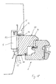
- a wall or wall 1 of a building contains for installation of a window 2 (see Fig. 2 ) or a door, a wall opening 3, at the reveal 4 a blind stick 5 is fixedly mounted.
- the blind stick 5 has, for example, an L-shaped cross section with a protruding leg 6 and is z. B. by means of fittings (not shown) on the wall 1 or der Leibung. 4 attached that it is arranged with its outer end face 7 approximately parallel to the outer side 8 of the wall 1.
- a mounting joint 9 between the blind stick 5 and the reveal 4 is foamed by means of an insulating PU mounting foam 10.
- As an extruded plastic strip includes a mounting base 13, which serves for fastening the profile strip 12 by means of a foam adhesive tape 14 on the outer end face 7 of the leg 6, and a web 15, which at the wall opening 3 facing the end of the mounting base 13 at right angles to this extending beyond the foam adhesive tape 14 and in the in Fig. 1 and 2 shown installation arrangement extends beyond the side surface 16 of the leg 6 of the blind stock 5 and thus covers the leg 6 optically.
- the web 15 has a length such that it extends beyond the leg 6 at least approximately 1 mm, and preferably approximately 3 to 5 mm. Furthermore, the web 15 rests on the inside on the end face 16 of the leg 6 of the blind stock 5 and thus forms a stop for positioning the profiled strip 12 on the blind stick 5 or on the leg 6 of the blind stock 5.
- the web 15 preferably has a on its front side 17 rough surface 18 on.
- the profile strip 12 further includes a Einputzschenkel 19 which protrudes on the foam adhesive tape 14 and the web 15 opposite Einputzseite 20 of the profile bar 12 in particular at right angles from the mounting base 13 and expediently opposite to the web 15 and a line of flight 40 of the web 15 is recessed inward ,
- An insulating layer 21 of a thermal insulation composite system (ETICS) is mounted on the outside of the wall or wall 1 and the outer end face 7 of the blind stock 5 and the leg 6 and extends to the profile bar 12 zoom.
- the Einputzschenkel 19 forms or contains a trigger edge 22 for a first layer of plaster 23, which is applied to the insulating layer 21.
- An anextrudieres to Einputzschenkel 19 fabric 24 is embedded as a reinforcement in the first layer of plaster 23.
- the jetty 15 forms or contains a second, front trigger edge 25 or withdrawal surface for a second layer of plaster 26, which forms a cover layer of the plaster of the insulating layer 21 as a wet plaster.
- the blind stick 5 is plastered on the outside of the outer environment 27 adjacent outer profile strip 12 ready and can already be provided with a paint.
- the profile strip 12 is firmly connected to the ETICS. With the blind stick 5, the profile strip 12 is movably connected by means of the foam adhesive tape 14 for a dilatation movement.
- One of the interior 28 facing the second or inner profile bar 12 ', which corresponds with its mounting base 13' and its web 15 'substantially the first profile bar 12 is on an inner end face 29 of the blind block 5 via its mounting base 13' by means of a foam adhesive tape 14 '. firmly attached, wherein the web 15 'extends over the edge region of the side surface 30 of the blind stick 5 and rests against it.
- Two Einputzschenkel extend from the mounting base 13 'at right angles, the front Einputzschenkel is set back relative to the web 15' and extends farther than a rear Einputzschenkel.
- the front Einputzschenkel contains openings that can accommodate a plaster and thereby stabilize it in the area on the profile strip.
- the approach of the web to the mounting base also forms a plaster removal edge for the interior plaster, which is applied to the soffit of the profile strip with a bevelled surface.
- Fig. 1 shows a ready-built blindfold 5 with the outer arrangement of the profiled strip 12 and the inner arrangement of the profiled strip 12 'with respective plaster application before a window 2 is fixed by means of his window 31 on the blind stick 5.
- Fig. 2 shows the window 31, which in its installed position on the blind stick 5 z. B. is firmly attached by screwing.
- a gap 32 between the outer Side surface 33 of the window stock 31 and the inner end 34 of the leg 6 of the blind stick 5 is sealed by a sealing tape, in particular a foam adhesive tape 35.
- the web 15 of the outer profile strip 12 extends against the outer side surface 33 of the window 31 and leaves only a narrow gap in front of the joint 32 open.
- An applied on the outer plaster 26 color layer which also covers the rough surface of the web 15, provides a uniform visual appearance to the window 31 and the narrow gap.
- At the inner environment 28 of the window sill 31 covers the profile bar 12 'and the web 15' completely off and an attached between the inner plaster 36 and the window 31 grouting 37 made of permanently elastic material forms an inside seal the rear joint 38 between the window 31 and the window Blindstock 5.
- the leg 6 is a strip
- the z. B. is made of aluminum or plastic and is attached to the frontal outer surface of the rectangular cross-section main body of the blind stock 5.
- one-piece blindstocks can be used.
- Fig. 4a shows an integral L-shaped blind stick 5, which projecting into the wall opening leg has a greater width than that in Fig. 4b shown, otherwise similar blind stick 5.
- the Indian Fig. 4e shown blind stick 5 has the basic shape according to Fig. 4a on and additionally contains a strip or leg 6 on its outer end face on which a profile strip on the outside according to the arrangement of Fig.1 is attached.
- the in Fig. 4f shown L-shaped blind stick 5 is an integral part, the z. B. is formed as a metal or plastic angle and at its base several (eg., Three) molded webs for anchoring PU foam, with which the blind stick 5 is fixed or the joint is filled with foam.
- Fig. 4g shows a blind stick 5 with a front side leg 6 ', which is attached by means of a only temporarily rigid attachment or a flexible attachment to the outer end side of the blind block 5.
- the leg 6 ' is formed at its front portion as a profile strip, which has a connection device for plaster in the form of at least one Einputzschenkels 19, so that a permanently fixed connection between the plaster and the profile strip 12 can be created.
- the two plasterable legs 19 'and 19 "protrude equidistant from the mounting base 13 at the same time, the front plastering leg 19' being flush with the web 15 and the rear plastering blade 19" fitting the end of the fastening leg 13.
- the web 15 ends with a soft lip 39, which offers a freedom of movement when installing a window or door frame due to its flexibility relative to a rigid end.
- the web 15 extends beyond the free adhesive surface of the foam adhesive tape addition, at least about 1 mm, preferably 3 to 5 mm and up to about 10 mm, so that the web 15 has a sufficient abutment surface for application to the side surface of a mounting part, for. B. the side surface 33 of the window stock 31 or the blind stock 5 has.
- the visible-side front side of the profiled strip 12 may contain a rough surface, so that plastic material such as paint or plaster can adhere better thereto.
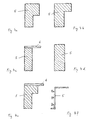
- Fig. 3c shows one opposite Fig. 3b modified profile strip 12, in which the two Einputzschenkel 19 'and 19 "protrude away at a particular same angle from the mounting base 13 and aligned with the front Einputzschenkel 19' web 15 is formed only in its stop forming the front portion at right angles to the mounting base 13.
- This profile strip 12 is particularly suitable for a diagonally plastered reveal (see Fig. 7 ), since the oblique arrangement of the outer Einputzschenkels 19 'follows this form.
- the profile strip 12 of Fig. 3d is a variation of the in Fig. 3a shown profile strip 12 with sloping Einputzschenkel 19 and web, the flexible lip according to Fig. 3b having.
- the respective web 15 has an end profile 41 extending in the direction of the attachment base 13, which forms a trigger edge (withdrawal surface) 42 for a cleaning tool at the end of the web 15.
- the end profile 41 is a strip of the same thickness, contains the profile strip 12 of Fig. 5a a tapered end profile 41, so that in a plaster application, the end profile 41 in comparison to the Fig. 5b is almost invisible.
- the profile strip contains the Fig. 5a a short front flush with the web 15 Einputzfortsatz 43 and two perpendicular to the mounting base 13 Einputzschenkel 19 'and 19 ", expediently also with an end formed as a barb.
- the two profile strips 12 of the Fig. 5c and 5d are modifications of the moldings 12 of Fig. 5a 5b, wherein both the webs 15 and the plastering legs 19, 19 'and 19 "are arranged obliquely, as in the previous exemplary embodiments, and contrary to the representation, the webs 15 could also be angled inwardly (as in FIG Fig. 3c shown).
- the end profile 41 of the web 15 is formed widened on its outer side (see Fig. 5c ) to provide a larger contact surface 42 for a plaster removal tool.
- the expiring as a cylindrical enlargement end profile 41 according to Fig. 5d also offers a more stable trigger edge. All profile strips 5a to 5d also have rough surfaces on the web 15 and the front Einputzschenkel as improved primer.
- profiled strip 12 includes a rear bevelled Einputzschenkel 19 'and a front Einputzschenkel 19, which is offset by, for example, about 2 to 3 mm from the web 15 inwardly, so that applied to a ground plaster, which formed up to a front Einputzschenkel 19 Putzabzugskante 43 is a fine or textured plaster can be applied with a thickness of about 2 to 3 mm, wherein the base of the web 15 forms the trigger edge 44 for this fine or textured plaster.
- the front Einputzschenkel 19 may have a profiling on the outside as a primer for the fine or textured plaster. Also on the inside, the front Einputzschenkel 19 may have a structuring or profiling as a primer, as well as the inner Einputzschenkel 19 '.
- the profile strip 12 of Fig. 5f contains a Einputzschenkel 19, which projects approximately at the center of the mounting base 13 at an angle, inside and outside has the same or different profiles, an embedded fabric 45 and openings 46 may include cleaning plaster.
- the web 15, which projects in particular at right angles from the fastening base 13, has on the front side one or more longitudinally projecting ribs 47, which form plaster removal edges and anchoring structures for a first plaster layer.
- the profile strip 12 of Fig. 6a (show a similar installation situation Fig. 15 and 16 ) has a comparatively long fastening base 13, from which a stop web 48 protrudes approximately centrally on the fastening side and subdivides these into an inner region 49 and an outer region 50.
- a foam adhesive tape 51 for attaching the profiled strip 12 to an end face of the blind stock 5 is attached to the inner region 49, and two foam tapes 52 and 52 'glued over one another are attached to the outer region 50, which can have different elastic properties and are adhered to a window frame 31 in the installed state become.
- a Einputzschenkel 19 projects upwards and a web 15 extends obliquely forward and downward.
- the web 15 carries at its front end a soft lip 39, to which the window frame 31 is applied during its installation.
- the window frame 31 is thereby pressed against the lower of the two foam strips 52 'and / or glued and compresses the two foam strips 52 and 52' accordingly maximum up to the height of the lip 39.
- a foam tape of appropriate thickness can be used instead of the two superposed foam tapes 52 and 52 'can only a foam tape of appropriate thickness can be used.
- the profile of the Fig. 6b which in contrast to the profile strip 12 of the Fig. 6a does not include a stop ridge, one from the attachment base 13 on the front side downwards projecting stop bar 15 for a window frame 31.
- a double-layer foam adhesive tape 52, 52 ' is attached to the attachment base 13, which protrudes downwards beyond the stop web 15 in the delivery condition.
- the double-layer foam tape consists z. Example of two superimposed glued foam adhesive tapes 52, 52 'with a cross section of about 6 by 7 mm.
- the profile strip 12 is attached to its attachment base 13 by means of an adhesive tape 53 on the blind stick 5 or its legs 6.
- a window frame is glued to the foam adhesive tape during installation and applied as far as possible to the stop web, wherein the double-layer foam adhesive tape is compressed accordingly.
- the profile strip 12 of Fig. 6c has at its mounting base 13, two downwardly projecting clamping webs 54 and 54 ', wherein the front clamping web 54 for engagement in a milled to a blind stick 5 groove 55 (see, eg. Fig. 13 ) and the rear clamping web 54 'for engagement with a shoulder 56 of the blind stock 5 (see eg. Fig. 11 ) is provided.
- ridge 15 projects downwards, which merges into a front mounting base 13a for a foam adhesive tape 52, which in turn has an upwardly projecting Einputzschenkel 19 and an obliquely forward and downward extending web 15a as an attachment for a window frame 31st carries (comparable to the Fig. 6a ).
- the profile strip 12 of Fig. 6d is a modification of the profile bar 12 of Fig. 6b and contains two upwardly projecting Einputzschenkel 19 and 19 'and a downwardly projecting web 15 with a parallel to the mounting base 13 extending end profile 41, which forms a trigger edge 42 for a cleaning tool at the end of the web 15 (see Fig. 5a ).
- the front Einputzschenkel 19 and the web 15 has a profiling for better adhesion of plaster.
- FIG. 7 the installation arrangement shown is a designated as angled, a paragraph having blindfold 5 attached to a soffit.
- a profile strip 12 according to Fig. 5b is fixed by means of the foam adhesive tape 14 on the outer end face 7 of the blind stock 5, wherein the long stop web 15 extends far beyond the side surface 16 of the blind stock 5 and plastered with plaster 26.
- the outer plane or outer side surface 33 of the window stock 31 is accordingly set back far inward.
- a profiled strip 12 'with a foam adhesive tape 14' is fixed such that the web 15 'projects beyond the side surface 16 of the blind block 5 and rests against it.
- a Putzanschlußsteg 19 ' is plastered flush with Najiputz 36.
- the Fig. 8 shows the installation arrangement of Fig. 7
- the window frame 31 includes for adaptation to the angled blind stick 5 at its outer corner a recess 57 to which a sealing strip 58, in particular a foam adhesive tape a sealing joint sealing connection to the blind stick 5 produces.
- the window frame 31 rests with its outer side 33 against the contact bar 15 of the profiled strip 12.
- connection strip 59 is fastened on the inside by means of a foam adhesive tape 60.
- Their elastic sealing lip 61 bears against the inner plaster layer 36 in an optically sealing manner.
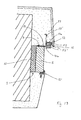
- a dummy stick 5 according to Fig. 4f attached to a soffit, wherein the mounting joint is foamed with foam 10.
- a profile strip 12 is attached by means of a foam adhesive tape.
- Her front oblique web 15 engages over the leg 6 of the blind stock 5 and covers it from the visible side.
- the recessed Einputzschenkel 19 is plastered with a first layer of plaster 23 which is oblique with respect to the soffit and extends to the web 15.
- a fine plaster layer 26 covers the web 15 to the front edge, which serves as a plaster removal edge 42 from.
- an inner profile strip 12 ' by means of a foam adhesive tape 14' fixed so that her sicht characterer web 15 ', the foam tape 14' overlaps and extends beyond the edge of the blind stock 5, to which it also rests.
- the window frame 31 is at installation ( Fig. 10 ) is applied to the web 15 and stop the outer profile strip 12 and a sealing tape, in particular a foam adhesive tape 58 is disposed in the joint between the window 31 and the blind stick 5 and glued to both.
- the rear mounting joint 9 between the window frame 31 and the blind stick 5 is foamed with foam 10, which also completely covers the inner profile strip 12 '.
- a Holzabdeckance 62 forms an inner end of the window frame 31 to the Leibungsputztik 36th
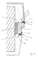
- a blind stick 5 attached to a soffit, wherein the mounting joint 9 is foamed with foam 10.
- the blind stick 5 includes on its outer end face 7 a protruding leg 6, which is clamped by two molded clamping webs 54 at two recesses or heels 56 of the blind stock 5 at this and thus forms a solid unit with the blind stick 5.
- a profiled strip 12 is fastened by means of a foam adhesive tape 14 such that its front web 15 engages over the side face 16 of the blind leg 6.
- a first layer of plaster 23 is applied to the front Einputzschenkel 19 and a second layer of plaster 26 extends to the front web 15, but does not cover it.
- an inner profile strip 12 ' is fixed to the inner end face 29 of the blind stock 5 with a foam adhesive tape 14', wherein its web 15 'engages over the edge of the blind stock 5 and rests against it.
- a sealing tape in particular a foam adhesive tape 58 fills the gap between them and seals by adhesive bonds on both sides of the blind leg 6 and the window frame 31.
- the per se rigid web 15 of the profile strip 12 includes a hinge 63, so that the lower portion of the web 15 is pivoted upon application of the window frame 31 to the required extent.
- the inner profile strip 12 ' is completely covered by the window frame 31.
- a Holzabdeckance 62 forms according to the above embodiment, an inner end.
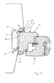
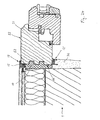
- a dummy stick 5 is fixed to a soffit consisting of a dummy stick body 5 and a dummy stick leg 6 fixed to the outer end face 7 of the dummy stick body 5, which projects beyond the side surface 5a of the stepped dummy stick body 5.
- the blind stick leg 6 is by means of a protruding clamping web 54 in a groove 55 formed in the blind stick main part 5 clamped.
- the fixing joint 9 between the blind stick 5 and the reveal is foamed with foam 10.
- a profiled strip 12 of an outer sealing connection is fastened to the outer end side 7a of the blind leg 6, wherein the profiled strip 12 has a stepped attachment base 13, at the front attachment base 13a a mounting arrangement in the form of a foam adhesive tape 14 connects the profiled strip 12 to the blind leg 6 and to the latter
- a sealing arrangement in the form of a slender and high two-layer foam adhesive tape 14a also permanently seals the profile strip 12 with the blind stock leg 6, even if the foam adhesive tape 14 of the assembly arrangement is subject to movements between the profiled strip 12 fixedly connected to the plaster compared to the front attachment base 13a and the blind stick 5 or blind stick 6 should tear.
- a front web 15 of the profiled strip 12 extends over the side surface 16 of the blind leg 6 until a foam adhesive tape 58 glued to the inner end side of the blind leg 6, which produces the sealing connection between the blind leg 6 and the window stock 31 when the window stock 31 is attached.
- An outer plaster layer 26 covers the web 15 on the outside and leaves only a narrow portion of the stop of the web 15 visible.
- the window stock 31 is located at the abutment end 48 of the web 15 of the profile strip 12 as in the preceding examples or is only slightly spaced therefrom.
- the likewise stepped window floor 31 is sealed by a sealing tape 64, in particular a foam adhesive tape at the stage to the blind stick 5 out.
- the built-in window floor 31 covers the visible web 15 'of the plastered profile strip 12' and is connected via an elastic sealant or grouting 37 with the jaw plaster 36.
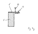
- a blind stick 5 In the installation arrangement of Fig. 15 and 16 (with window) is a blind stick 5, z. B. made of wood with a rectangular cross section, attached to a soffit, wherein the attachment joint 9 is foamed between the blind stick 5 and the reveal with foam 10.
- a profile strip 12 according to Fig. 6a is attached to the outer end face 7 of the blind stock 5 by means of the rear foam adhesive tape 51 such that the stop leg or stop ridge 48 rests on the blind stick 5 and its side surface covers the edge.
- the profile strip 12 may additionally be secured in the region of the foam adhesive tape 51 by means of a nail 65 on the blind stick 5, which serves only as a transport or mounting backup and can be removed before applying the full thermal protection again.
- the profile strip 12 is plastered to the top of the web 15.
- the connecting seal between the window frame and the front attachment base 13a of the outer profile strip 12 is made with a single-layer sealing strip 52, in particular a foam adhesive tape (see Fig. 15 ) or with a two- or multi-layer sealing tape (see Fig. 16 ).
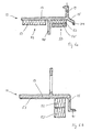
- Fig. 17 and 18 In the installation arrangement of Fig. 17 and 18 (with window) is again a blind stick 5, z. B. made of wood with a rectangular cross section, attached to a soffit, wherein the attachment joint 9 is foamed between the blind stick 5 and the reveal with foam 10.
- a profiled strip 12 of an external plaster connection device is again fastened by means of a web 55 inserted in a groove 55 on the outer end side of the blind stock 5 and forms a detachably connected to the blind stick 5 part of the blindstocks 5.
- the profiled strip 12 but additionally contains a Putzan gleich Rheinwald 19 and 19 'and the stop 41 on the web 15a for a window frame to be installed 31.
- the web 15 is made with such a length (the length is its extension in the direction of the side surface of the blind block 5), as required by the installation position of the window frame 31.
- the built-in window frame 31 abuts the tip of the front stop 41 and compresses the fastening and sealing sealing strip 52 accordingly.
- the room interior side profile strip 12 'arranged comparable to the above examples is completely covered by the installed window frame 31.
- the window frame 31 is toward the space inside plaster 36 through a seal 59, 60, 61 according to Fig. 8 connected.
- a blind stick 5 In the installation arrangement of Fig. 19 and 20 (with window) is again a blind stick 5, z. B. made of wood with a rectangular cross section, attached to a soffit, wherein the attachment joint 9 is foamed between the blind stick 5 and the reveal with foam 10.
- a profile strip 12 is attached to the outer end face 7 of the blind block 5 and forms part of this blind block 5.
- the mounting base 13 extends beyond the plane of the side surface of the blind block 5 and can form in this section a stop 41a for a window frame 31 to be installed.
- An upwardly projecting Einputzschenkel 19 ' is the front side in a recessed mounting base 13a for a double-layer foam adhesive tape 52, 52' away and eventually goes into a front web 15, which again reaches up to the height of the mounting base 13 of the profile bar 12 and also a Stop 41 can form a window frame 31 to be installed.
- the profile bar 12 with the plaster 23 is firmly connected. With relative movements between the plaster 23 or the profile strip 12 fixed thereto and the blind stick 5, the attachment of the profile strip 12 can be detached from the blind stick 5 and provide for a necessary compensating movement between these parts.
- a blind stick 5 In the installation arrangement of Fig. 21 and 22 (with window) is again a blind stick 5, z. B. made of wood with a stepped cross-section, attached to a soffit, wherein the fastening joint 9 is foamed between the blind stick 5 and the reveal with foam 10.
- a profile strip 12 for example, the in Fig. 5e Profile strip shown, is on the outer end face 7 of the blind stock 5 by means a foam adhesive tape 14 attached.
- the web 15 extends over an edge portion of the side surface of the blind stock 5 and serves as an assembly aid or assembly stop and as a trigger edge when applying an upper layer of plaster 26 on the Einputzschenkel 19, while the web 15 remains clean on the visible side.
- the same profile strip 12 ' is attached as a space inside connection device on the blind stick 5 opposite to the outer profile strip 12 and plastered with plaster 36, wherein here too the web 15' and its front remains unpowdered.
- the built-in window frame 31 covers both profile strips 12 and 12 'and is by means of elastic seals 37 with the plaster 26 and 36 in addition to the two profile strips 12 and 12' tightly connected.
- the Fig. 23 and 24 each show an arrangement of a window frame 31 on a reveal of masonry 1 without the interposition of a dummy block.
- the a room interior Putzanschlußan Aunt forming profile strip 12 'of Fig. 23 is attached by means of a foam adhesive tape 52 'on the mounting joint or the soffit facing end face or rear side 66 of the window frame 31.
- the web 15 engages over the edge region of the inner side surface or inner side 67 of the window frame 31 facing the inner space, and its front surface remains visible even after the application of a Leibungsputz layer.
- the web 15 ' is located as an assembly aid when attaching the profile strip 12' on the inside 67 of the window frame 31 at.
- the a room outside Putzanschlußan extract forming profile strip 12 of Fig. 24 is fastened in a comparable manner via its attachment base 13 by means of a foam adhesive tape 52 on the end face or rear side 66 of the window frame 31 facing the assembly joint or the reveal.
- the profile strip 12 also essentially corresponds to that of Fig. 3a ,
- the web 15 engages over the edge region of the outside space facing outer side or outside 33 of the window frame 31 and its front surface remains even after the application of an outer plaster or filler layer visible, noticeable.
- the web 15 is as an assembly aid when attaching the profile strip 12 on the outside 33 of the window frame 31 at.
- a room inside cleaning connection bar 12 'of known design represents the inside transition between the window frame 31 and the plaster layer 36 on the wall of the interior.
- the described devices can also be used in door frames instead of window frames.
Landscapes
- Engineering & Computer Science (AREA)
- Civil Engineering (AREA)
- Structural Engineering (AREA)
- Building Environments (AREA)
- Door And Window Frames Mounted To Openings (AREA)
Applications Claiming Priority (1)
| Application Number | Priority Date | Filing Date | Title |
|---|---|---|---|
| DE200710003510 DE102007003510A1 (de) | 2007-01-24 | 2007-01-24 | Profilleistenanordnung an einem Blindstock |
Publications (2)
| Publication Number | Publication Date |
|---|---|
| EP1953329A2 true EP1953329A2 (fr) | 2008-08-06 |
| EP1953329A3 EP1953329A3 (fr) | 2011-04-06 |
Family
ID=39327236
Family Applications (1)
| Application Number | Title | Priority Date | Filing Date |
|---|---|---|---|
| EP08001256A Withdrawn EP1953329A3 (fr) | 2007-01-24 | 2008-01-23 | Agencement de bande profilée par un cadre de dormant pour fenêtres ou portes |
Country Status (2)
| Country | Link |
|---|---|
| EP (1) | EP1953329A3 (fr) |
| DE (1) | DE102007003510A1 (fr) |
Cited By (2)
| Publication number | Priority date | Publication date | Assignee | Title |
|---|---|---|---|---|
| EP2669459A1 (fr) * | 2012-05-30 | 2013-12-04 | Sto Ag | Dispositif de fermeture d'un joint de dilatation placé au niveau de la façade d'un bâtiment |
| EP2762668A3 (fr) * | 2013-02-01 | 2015-10-07 | Af Tec Beteiligungs Gmbh | Profil de raccordement |
Families Citing this family (1)
| Publication number | Priority date | Publication date | Assignee | Title |
|---|---|---|---|---|
| DE102008038009B4 (de) * | 2008-08-16 | 2017-10-05 | Rehau Ag + Co | Profilleiste und Möbelstück |
Citations (2)
| Publication number | Priority date | Publication date | Assignee | Title |
|---|---|---|---|---|
| AT292988B (de) | 1968-04-08 | 1971-09-27 | Wick Josef & Soehne | Fenster oder Tür mit hölzernem Blindstock |
| DE102007003511A1 (de) | 2007-01-24 | 2008-08-14 | Konrad Lehrhuber | Bauprofilleiste aus Kunststoff mit einer Oberflächenverankerungsstruktur für Putz |
Family Cites Families (11)
| Publication number | Priority date | Publication date | Assignee | Title |
|---|---|---|---|---|
| DE1871361U (de) * | 1963-01-07 | 1963-05-02 | Manfred Hans Gemuenden | Uebergangsprofil an tuer- bzw. fensterrahmen. |
| DE19700107B4 (de) * | 1997-01-03 | 2012-01-26 | August Braun | Expansionsfähige Leiste für den Übergang zwischen einem Fensterstock, Türstock oder dergleichen und einer anschließenden Putzschicht |
| DE20008712U1 (de) * | 2000-05-16 | 2000-08-03 | Lehrhuber, Konrad, Dipl.-Ing. (FH), 84144 Geisenhausen | Profilleiste zum Abdichten einer Bewegungsfuge zwischen einem Bauteil und einer Putzschicht |
| DE10066070A1 (de) * | 2000-05-16 | 2004-06-03 | Lehrhuber, Konrad, Dipl.-Ing. (FH) | Profilleiste zum Abdichten einer Bewegungsfuge zwischen einem Bauteil und einer Putzschicht |
| AT413122B (de) * | 2000-11-14 | 2005-11-15 | Peter Kassmannhuber | Anschlussprofil für putz- oder spachtelanschlüsse an angrenzende bauteile |
| DE50310426D1 (de) * | 2002-07-18 | 2008-10-16 | Peter Kassmannhuber | Laibungsanschlussprofil |
| EP3156558A1 (fr) * | 2002-12-05 | 2017-04-19 | Konrad Dipl.-Ing. Lehrhuber | Barre profilée de jonction pour un passage entre un composant et une paroi de bâtiment |
| DE10354968A1 (de) * | 2003-11-25 | 2005-06-30 | Armin Pohle | Leiste für den Rahmenbau, Rahmen, Montagekeil, Winkellehre, Fensterbank |
| DE20319377U1 (de) * | 2003-12-12 | 2004-06-03 | Blos, Alfred | Hilfsprofilleiste mit Putzanschlag für den Fenster- und Türrahmeneinbau |
| DE202004017341U1 (de) * | 2004-11-08 | 2005-01-20 | Beck, Walter, Dipl.-Ing. | Profilleiste zum Herstellen eines Übergangs zwischen einem Bauteil und einer Gebäudefläche |
| DE102005002177A1 (de) * | 2005-01-17 | 2006-07-27 | Konrad Lehrhuber | Abdichtungsanordnung und Verfahren zum Herstellen einer Abdichtung |
-
2007
- 2007-01-24 DE DE200710003510 patent/DE102007003510A1/de not_active Ceased
-
2008
- 2008-01-23 EP EP08001256A patent/EP1953329A3/fr not_active Withdrawn
Patent Citations (2)
| Publication number | Priority date | Publication date | Assignee | Title |
|---|---|---|---|---|
| AT292988B (de) | 1968-04-08 | 1971-09-27 | Wick Josef & Soehne | Fenster oder Tür mit hölzernem Blindstock |
| DE102007003511A1 (de) | 2007-01-24 | 2008-08-14 | Konrad Lehrhuber | Bauprofilleiste aus Kunststoff mit einer Oberflächenverankerungsstruktur für Putz |
Cited By (2)
| Publication number | Priority date | Publication date | Assignee | Title |
|---|---|---|---|---|
| EP2669459A1 (fr) * | 2012-05-30 | 2013-12-04 | Sto Ag | Dispositif de fermeture d'un joint de dilatation placé au niveau de la façade d'un bâtiment |
| EP2762668A3 (fr) * | 2013-02-01 | 2015-10-07 | Af Tec Beteiligungs Gmbh | Profil de raccordement |
Also Published As
| Publication number | Publication date |
|---|---|
| EP1953329A3 (fr) | 2011-04-06 |
| DE102007003510A1 (de) | 2008-07-31 |
Similar Documents
| Publication | Publication Date | Title |
|---|---|---|
| DE19605467B4 (de) | Anputzleiste für Fensterstöcke, Türstöcke oder dergleichen am Übergang zu Putz | |
| EP1479848B1 (fr) | Profilé de raccord pour plâtre sur éléments de construction voisins | |
| EP1808565B1 (fr) | Agencement d'étanchéité et profilé pour un agencement d'étanchéité | |
| EP2404009B1 (fr) | Bande de raccordement de profilé avec dispositif d'étanchéité pour l'étanchéité des joints | |
| EP1698742B1 (fr) | Profil de bord pour éléments de construction à la connexion avec le crépi et un feuil isolant | |
| EP1942237B1 (fr) | Bande pour crépi en deux pièces | |
| EP2511465B1 (fr) | Profilé de bordure et procédé de montage d'un rebord de fenêtre | |
| EP1674649B1 (fr) | Profilé de raccord à deux pièces pour éléments de construction voisins d'un crépi | |
| EP1707727A2 (fr) | Dispositif d'étanchéité et procédé de fabrication d'un joint d'étanchéité | |
| EP1947280A2 (fr) | Baguette de raccordement à profilé pour un passage de composant vers une paroi d'immeuble | |
| EP2952649B1 (fr) | Baguette de finition embrochable | |
| WO2014033005A1 (fr) | Profilé pour joints | |
| EP1953329A2 (fr) | Agencement de bande profilée par un cadre de dormant pour fenêtres ou portes | |
| AT8398U1 (de) | Zweiteiliges laibungsanschlussprofil | |
| DE102005012537B3 (de) | Profilleiste zum Anschließen einer Verkleidungsplatte, insbesondere einer Leibungsauskleidungsplatte an ein Bauteil, insbesondere einen Fenster- oder Türstock oder eine Rolloschiene | |
| AT6500U1 (de) | Laibungsanschlussprofil | |
| EP2607571B1 (fr) | Panneau d'habillage pour le montage dans un intrados ou un linteau | |
| EP2171175B1 (fr) | Baguette de raccordement d'enduit pour la douelle de fenêtres et de portes | |
| DE102014116372B4 (de) | Profilleiste zur Anbringung an einem unteren Rahmenschenkel eines Fenster- oder Türrahmens im Bereich des Übergangs zum Mauerwerk | |
| EP2270304A2 (fr) | Profilé d'enfichage et/ou d'introduction | |
| AT11160U1 (de) | Führungsschiene für einen rolladen, sonnen- oder insektenschutz und wand mit einer führungsschiene | |
| DE202015106791U1 (de) | Profilleiste zur Anbringung an einem unteren Rahmenschenkel eines Fenster- oder Türrahmens im Bereich des Übergangs zum Mauerwerk | |
| EP1548222A1 (fr) | Profilé pour joindre une couche d'enduit ou de mortier de carrelage à un élément de construction | |
| AT521043A4 (de) | Zusatzteil | |
| DE102007029223A1 (de) | Putzanschlussleiste für die Laibung von Fenstern und Türen |
Legal Events
| Date | Code | Title | Description |
|---|---|---|---|
| PUAI | Public reference made under article 153(3) epc to a published international application that has entered the european phase |
Free format text: ORIGINAL CODE: 0009012 |
|
| AK | Designated contracting states |
Kind code of ref document: A2 Designated state(s): AT BE BG CH CY CZ DE DK EE ES FI FR GB GR HR HU IE IS IT LI LT LU LV MC MT NL NO PL PT RO SE SI SK TR |
|
| AX | Request for extension of the european patent |
Extension state: AL BA MK RS |
|
| PUAL | Search report despatched |
Free format text: ORIGINAL CODE: 0009013 |
|
| AK | Designated contracting states |
Kind code of ref document: A3 Designated state(s): AT BE BG CH CY CZ DE DK EE ES FI FR GB GR HR HU IE IS IT LI LT LU LV MC MT NL NO PL PT RO SE SI SK TR |
|
| AX | Request for extension of the european patent |
Extension state: AL BA MK RS |
|
| AKY | No designation fees paid | ||
| REG | Reference to a national code |
Ref country code: DE Ref legal event code: R108 |
|
| REG | Reference to a national code |
Ref country code: DE Ref legal event code: R108 Effective date: 20111214 |
|
| STAA | Information on the status of an ep patent application or granted ep patent |
Free format text: STATUS: THE APPLICATION IS DEEMED TO BE WITHDRAWN |
|
| 18D | Application deemed to be withdrawn |
Effective date: 20110801 |