EP1950492B1 - Eclairage pour véhicules, de préférence pour véhicules automobiles - Google Patents
Eclairage pour véhicules, de préférence pour véhicules automobiles Download PDFInfo
- Publication number
- EP1950492B1 EP1950492B1 EP08000996A EP08000996A EP1950492B1 EP 1950492 B1 EP1950492 B1 EP 1950492B1 EP 08000996 A EP08000996 A EP 08000996A EP 08000996 A EP08000996 A EP 08000996A EP 1950492 B1 EP1950492 B1 EP 1950492B1
- Authority
- EP
- European Patent Office
- Prior art keywords
- light
- lens
- lamp according
- lamp
- windows
- Prior art date
- Legal status (The legal status is an assumption and is not a legal conclusion. Google has not performed a legal analysis and makes no representation as to the accuracy of the status listed.)
- Expired - Fee Related
Links
Images
Classifications
-
- B—PERFORMING OPERATIONS; TRANSPORTING
- B60—VEHICLES IN GENERAL
- B60Q—ARRANGEMENT OF SIGNALLING OR LIGHTING DEVICES, THE MOUNTING OR SUPPORTING THEREOF OR CIRCUITS THEREFOR, FOR VEHICLES IN GENERAL
- B60Q1/00—Arrangement of optical signalling or lighting devices, the mounting or supporting thereof or circuits therefor
- B60Q1/26—Arrangement of optical signalling or lighting devices, the mounting or supporting thereof or circuits therefor the devices being primarily intended to indicate the vehicle, or parts thereof, or to give signals, to other traffic
- B60Q1/2607—Arrangement of optical signalling or lighting devices, the mounting or supporting thereof or circuits therefor the devices being primarily intended to indicate the vehicle, or parts thereof, or to give signals, to other traffic comprising at least two indicating lamps
-
- B—PERFORMING OPERATIONS; TRANSPORTING
- B60—VEHICLES IN GENERAL
- B60Q—ARRANGEMENT OF SIGNALLING OR LIGHTING DEVICES, THE MOUNTING OR SUPPORTING THEREOF OR CIRCUITS THEREFOR, FOR VEHICLES IN GENERAL
- B60Q1/00—Arrangement of optical signalling or lighting devices, the mounting or supporting thereof or circuits therefor
- B60Q1/26—Arrangement of optical signalling or lighting devices, the mounting or supporting thereof or circuits therefor the devices being primarily intended to indicate the vehicle, or parts thereof, or to give signals, to other traffic
- B60Q1/30—Arrangement of optical signalling or lighting devices, the mounting or supporting thereof or circuits therefor the devices being primarily intended to indicate the vehicle, or parts thereof, or to give signals, to other traffic for indicating rear of vehicle, e.g. by means of reflecting surfaces
- B60Q1/304—Adaptations of signalling devices having a part on the vehicle body and another on the boot door
-
- F—MECHANICAL ENGINEERING; LIGHTING; HEATING; WEAPONS; BLASTING
- F21—LIGHTING
- F21S—NON-PORTABLE LIGHTING DEVICES; SYSTEMS THEREOF; VEHICLE LIGHTING DEVICES SPECIALLY ADAPTED FOR VEHICLE EXTERIORS
- F21S43/00—Signalling devices specially adapted for vehicle exteriors, e.g. brake lamps, direction indicator lights or reversing lights
- F21S43/20—Signalling devices specially adapted for vehicle exteriors, e.g. brake lamps, direction indicator lights or reversing lights characterised by refractors, transparent cover plates, light guides or filters
- F21S43/26—Refractors, transparent cover plates, light guides or filters not provided in groups F21S43/235 - F21S43/255
-
- F—MECHANICAL ENGINEERING; LIGHTING; HEATING; WEAPONS; BLASTING
- F21—LIGHTING
- F21S—NON-PORTABLE LIGHTING DEVICES; SYSTEMS THEREOF; VEHICLE LIGHTING DEVICES SPECIALLY ADAPTED FOR VEHICLE EXTERIORS
- F21S43/00—Signalling devices specially adapted for vehicle exteriors, e.g. brake lamps, direction indicator lights or reversing lights
- F21S43/20—Signalling devices specially adapted for vehicle exteriors, e.g. brake lamps, direction indicator lights or reversing lights characterised by refractors, transparent cover plates, light guides or filters
- F21S43/255—Filters
Definitions
- the invention relates to a luminaire for vehicles, preferably for motor vehicles, according to the preamble of claim 1.
- a luminaire which is designed as a headlight for vehicles.
- the lamp has a housing, a lens and a light source.
- the lens has in the center a first partial surface with optical deflection properties. In the outer edge region between this partial surface and the lens, this is at least partially transparent. By this measure, a sharp contour of the first central part surface is achieved, which also also has optical Blink properties.
- a luminaire is known with a subdivided into several chambers housing, each chamber is equipped with a light source and each chamber each fulfills different signal functions. At least the chambers are covered by a transparent lens.
- the lens consists of several segments.
- An opaque mask is disposed between the housing and the lens. It separates different chambers associated parts of the lens.
- the mask may cover the bulb of one or more chambers, whereby a chamber appears as two separate chambers.
- the mask 22 is provided on the side facing the lamp with a mirror coating.
- the mask is provided on the side facing away from the bulb with reflectors.
- the lens itself is translucent at every point.
- EP 0 442 095 A2 is a tail light with a housing and a lens known. At least one light source is provided behind the lens.
- the lens is divided into at least two separate, translucent and spaced-apart light windows having the same or different lighting functions and between which at least one formed by a housing belonging to the web, at least partially opaque area is present.
- colored, opaque strips are applied from the inside to the light window in the embossing process.
- the invention has for its object to design the generic lamp so that their split light windows are perceived in a simple design and cost-effective production in the illuminated state as a closed luminous area.
- a luminaire in which the lens is divided into different light windows. Within a light window colored, opaque strips are provided to make the lens appear in the off state of the lamp from the view of a distant observer in the area of the white reversing light in a uniform red hue.
- the luminaire according to the invention is located in the opaque area between the two light windows of the additional transparent area. It is achieved that, despite the split light window, a coherent light window required by the legislator can be recognized by a viewer if the two light windows fulfill the same lighting function.
- the additional translucent area can be small. It is arranged in the intermediate area between the light windows so that a viewer perceives all the light windows as a single light window.
- the non-luminous intermediate areas blur at a certain distance in the eye of the beholder, so that he no longer perceives the light windows and the additional translucent area as a single light window.
- Such light windows in luminaires are of particular interest when design-relevant areas of the luminaire are to act as part of the bodywork. A division into individual light windows is then no longer avoidable. As an alternative, then only the enlargement of the lamp is available in total, since the legal minimum surfaces of the light functions of the lamp must be met. However, such large lights are unacceptable for aesthetic reasons. With the luminaire according to the invention, the legal minimum surfaces of the lighting functions can be fulfilled without the luminaire having to be enlarged overall.
- the lamp according to the invention also has the advantage that it can be produced very inexpensively, since essentially the same tools as standard lamps can be used.
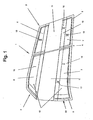
- Fig. 1 shows a lamp 1 with two separate light windows 6, 7 for a common light or signal function.
- the light 1 is a rear light for motor vehicles, which is divided into two parts 2 and 3.
- the parting line 3 of the light parts 2, 3 is located between the body of the motor vehicle and the rear lid flap.
- the light part 2 is attached to the body side in the fender, while the light part 3 is fixed in or on the trunk lid or trunk lid.
- the body-side light part 2 is exemplarily smaller than the flap-side light part 3.
- the proportions may also be reversed, or both light parts 2, 3 may have the same size.
- the luminaire parts 2, 3 can have very different outlines.
- Both light parts 2, 3 each have the upper light window 6 and the lower light window 7, which are each separated by an opaque or partially transmissive region 11 from each other. This is arranged substantially centrally to the luminaire parts 2, 3.
- the area 11 is, for example, a colored or painted in the body color part of a lens 20, which closes the lamp 1 on one side. Behind the area 11, at least one light source 31 (FIG. Fig. 3 to 5 ), which only this area 11 is similar to a position light in a weak, dull light appears or illuminated.
- the light-emitting means 31 is an incandescent lamp in the exemplary embodiment, but it can also be an LED or another light source.
- the bulb sits in a socket 32 to which electrical leads 33 are connected to power the incandescent lamp.
- each luminaire part 2, 3 can be connected to each other within the luminaire 1.
- a single illuminant 31 is sufficient if its light is reflected by a common reflector 30 to the light windows. An outside observer then has the impression that it is two individual lights.
- each a separate lighting area may be provided, which has at least one lamp 31 and at least one reflector 30.
- the two light windows 6, 7 of the light parts 2, 3 can be assigned the same light functions 15 and different light functions 15, 17.
- the upper light window 6 of the flap-side light part 3 may have the same light function 15 to 17 as the upper and lower light windows 6, 7 of the body-side light part 2.
- the lower light window 7 of the flap-side light part 3 may be divided into two or more different light functions, for example ,
- the lower half can be designed, for example, as a rear fog lamp 16 or reversing light 19.
- the upper half of this lower light window 7 can form, for example, a reflection reflector 18.
- a wide variety of combinations and connections are possible with these light functions.
- the light windows 6, 7 of the body-side light part 2 have a multiple light function, for example, with an existing tail light 15th a direction indicator 17 may be combined.
- a direction indicator 17 may be combined.
- the tail light 15 is formed by the two light windows 6, 7 of the body-side light part 2.
- the tail light 15 in the case of a rear light in which the taillight 15 is divided into a plurality of independently spaced fields must together amount to 60% of the area of the entire rear light. This rule does not apply to non-divided areas 6, 7.
- the tail light 15 always appears as a continuous contiguous area.
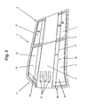
- the body-side light part 2 in the opaque region 11 between the upper and the lower light window 6, 7 strip-shaped light-transmitting regions 21 are provided. They are additional small light windows which have the same light functions as the upper and / or lower light windows 6, 7 of the luminaire part 2.
- the upper edge of the area 21 is arranged no more than 15 mm away from the lower edge of the upper light window 6.
- the same condition applies to the lower edge of the area 21, which must have a maximum distance of 15 mm from the upper edge of the lower light window 7. This small distance ensures that the observer standing at the back perceives the luminaire 1 viewed from a distance as a continuous light window 6, 7, 21.
- the area 21 can also be one-piece Be formed area. Is the area 21, like Fig. 2 shows, from a plurality of individual strip-shaped elements 21, the distance between adjacent elements 21 may not be greater than 15 mm.
- the areas 21 can lie both in the left and in the right half and in the middle between the upper and lower light windows 6, 7.
- the areas 21 have a rectangular strip shape. Other shapes are possible, provided that the impression is created that the upper and lower light windows 6, 7 are connected to each other.
- the regions 21 may be circles or may have elliptical or rounded, triangular or polygonal shapes.
- the regions 21, like the individual light windows 6, 7, can have a plurality of different light functions.
- the light window 6 may be formed as the tail light 15 with a partially delimiting area as the direction indicator 17, while the lower light window 7 serves exclusively as the tail light 15.
- the areas 21 can be operated in this case as a turn signal 17 and / or as a tail light 15.
- the use of such areas 21 is not limited only to the body-side light part 2.
- the flap-side lighting part 3 may have such areas 21.
- strip-shaped regions 21 may be arranged in the outer edge region of the two luminous parts 2, 3. This creates the effect that the lamp 1 appears as a closed frame.
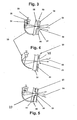
- Fig. 3 shows a section through the lamp 1, which is provided with the lens 20. It consists of two layers 22, 23, which are joined together, for example, in a multi-injection process to the lens 20.
- the opaque region 11 is a longitudinally extending strip-shaped light transmission area 25 provided. When spraying the one layer 22, the plastic penetrates into the light passage region 25, wherein a corresponding thickening 27 is formed. Subsequently, the outer layer 23 is injected onto the inner layer 22, the thickness of which corresponds at least approximately to the height of the thickening 27.
- the opaque region 11 has three strip-shaped, at a distance parallel to each other lying Licht manlass Symposiume 25. Accordingly, the inner layer 22 is provided with three thickened 27.
- the outer layer 23 consists in the exemplary embodiment of an opaque and semi-transparent, strongly colored material, which enters into a non-detachable connection with the inner layer 22 during the spraying process.
- the outside of the layer 23 and the end faces of the thickenings 27 form a continuous homogeneous flat surface on the finished lens 20.
- the inner layer 22 of the lens 20 is made of transparent material or dyed so that the light rays 24 can pass freely to the outside.
- On the outer side of the outer layer 23 of the lens 20 may reflective structures or other externally visible structures, such as the reflectors 18, be applied.
- a coating 34 is applied on the inner layer of the lens 20, a coating 34 is applied.
- the coating 34 is provided with interruptions 35.
- the inner layer 22 has no thickenings to form the regions 21.
- the coating 34 forms the outside of the lens 20 and may be a color coating or a foil coating.
- the embodiment is according to Fig. 4 the same as the one after Fig. 3 ,
- the areas 21 for the painting process must be masked.
- parts may be removed from the film to form the areas. These missing parts form the light-transmissive regions 21 after the film has been attached to the layer 22.
- the light emitted by the luminous means 31 is transmitted via the reflector 18 or directly (as described in connection with FIG Fig. 3 described) pass through the layer 22 and the light-transmissive regions 21 to the outside.
- the film 34 can be produced easily and inexpensively and applied to the layer 22. There is no expensive and expensive spraying required as in the embodiment of Fig. 3 ,
- Fig. 5 shows an embodiment in which the inner layer 22 of the lens 20 is formed the same as in the embodiment according to Fig. 3 ,
- the layer 22 has the thickening 27 to form the light-transmissive regions 21.
- the outer layer 23 is completely enveloped by the coating 34, which may be, for example, a color or foil coating.
- the outer layer 23 of the lens 20 is produced in a first step in a plastic injection molding process.
- the layer 23 is coated with the coating 34.
- the coated Part inserted into an injection mold, in which the inner layer 22 of the lens 20 is molded with the thickening 27.
- the inner layer 22 with the thickening 27 is advantageously made of transparent, colored transparent or different from the outer layer 23 material.
- the layer 22 with the thickening 27 is produced in a first injection molding process.
- the outer layer 23 provided with the coating 34 is then placed on the inner layer 22 and bonded to it by means of an adhesive or welding process.
- the coating 34 may be provided on the layer 22 and / or on the layer 23 with one or different structures. They can be used for better reflection within the luminaire 1.
- the coating 34 on the inner and on the outer layer 22, 23 may be formed in different materials and / or color designs.
Landscapes
- Engineering & Computer Science (AREA)
- Mechanical Engineering (AREA)
- General Engineering & Computer Science (AREA)
- Non-Portable Lighting Devices Or Systems Thereof (AREA)
Claims (13)
- Lampe (1) pour véhicules, de préférence pour véhicules automobiles, comprenant un boîtier et un disque lumineux (20), derrière lequel est prévu au moins un moyen d'éclairage et qui est divisé en au moins deux fenêtres de lumière (6, 7) séparées, transparentes et disposées à distance l'une de l'autre, qui ont des fonctions d'éclairage identiques et/ou différentes et entre lesquelles est présente au moins une zone (11) au moins en partie opaque,
caractérisée en ce que
le disque lumineux (20) présente entre les fenêtres de lumière (6, 7) de fonction d'éclairage identique et/ou différente au moins une zone (11) opaque, zone (11) opaque dans laquelle est disposée au moins une zone (21) transparente supplémentaire, au moins une fonction d'éclairage d'au moins une fenêtre de lumière (6, 7) étant attribuée à la au moins une zone (21) transparente. - Lampe selon la revendication 1,
caractérisée en ce que la zone (21) transparente est conçue en forme de bande ou présente un contour rond, ovale ou anguleux. - Lampe selon la revendication 1 ou 2,
caractérisée en ce que la distance entre les bords des
fenêtres de lumière (6, 7) et la zone (21) transparente supplémentaire est inférieure à environ 15 mm. - Lampe selon l'une quelconque des revendications 1 à 3,
caractérisée en ce que la distance entre les bords d'au moins deux zones (21) transparentes et espacées l'une de l'autre est inférieure à environ 15 mm. - Lampe selon l'une quelconque des revendications 1 à 4,
caractérisée en ce qu'une source de lumière (31) commune ou à chaque fois au moins une source de lumière (31) est attribuée à la zone (21) transparente et aux fenêtres de lumière (6, 7). - Lampe selon l'une quelconque des revendications 1 à 5,
caractérisée en ce que la zone (21) transparente éclaire dans une couleur différente des fenêtres de lumière (6, 7) et en ce que, de façon avantageuse, un réflecteur (30) commun est attribué aux fenêtres de lumière (6, 7) à l'intérieur de la lampe (1) ou un réflecteur (30) est attribué à chaque fenêtre de lumière (6, 7). - Lampe, en particulier selon l'une quelconque des revendications 1 à 6,
caractérisée en ce que le disque de lumière (20) est constitué d'au moins deux couches (22, 23). - Lampe selon la revendication 7,
caractérisée en ce qu'une couche (23) extérieure du disque de lumière (20) est interrompue dans la zone (21) transparente et est opaque ou transparente avantageusement pour des faisceaux lumineux (24) du moyen d'éclairage (31). - Lampe selon la revendication 8,
caractérisée en ce qu'une couche (22) intérieure du disque de lumière (20) présente au moins un épaississement (27) qui s'engage dans l'interruption de la couche (23) extérieure. - Lampe selon l'une quelconque des revendications 7 à 9,
caractérisée en ce que la couche (23) extérieure du disque de lumière (20) est appliquée au moyen d'un procédé d'injection multicouche sur la couche (22) intérieure. - Lampe selon la revendication 9 ou 10,
caractérisée en ce que l'épaississement (27) de la couche (22) intérieure est à base d'un autre matériau et/ou présente une autre couleur que la couche (22) intérieure. - Lampe selon l'une quelconque des revendications 7 à 11,
caractérisée en ce que la couche (23) extérieure du disque de lumière (20) est dotée d'un revêtement (34) enveloppant, qui est avantageusement un revêtement de laque ou un revêtement de feuille. - Lampe selon l'une quelconque des revendications 9 à 12,
caractérisée en ce que le côté avant de l'épaississement (27) de la couche (22) intérieure et le côté extérieur de la couche (23) extérieure du disque de lumière (20) sont disposés sensiblement au même niveau et en ce que, de façon avantageuse, l'épaississement (27) de la couche (22) intérieure présente une optique ou une structure optique.
Priority Applications (1)
| Application Number | Priority Date | Filing Date | Title |
|---|---|---|---|
| SI200830013T SI1950492T1 (sl) | 2007-01-25 | 2008-01-19 | Svetilo za vozila prednostno za motorna vozila |
Applications Claiming Priority (1)
| Application Number | Priority Date | Filing Date | Title |
|---|---|---|---|
| DE102007005551A DE102007005551A1 (de) | 2007-01-25 | 2007-01-25 | Leuchte für Fahrzeuge, vorzugsweise für Kraftfahrzeuge |
Publications (2)
| Publication Number | Publication Date |
|---|---|
| EP1950492A1 EP1950492A1 (fr) | 2008-07-30 |
| EP1950492B1 true EP1950492B1 (fr) | 2009-12-02 |
Family
ID=39283905
Family Applications (1)
| Application Number | Title | Priority Date | Filing Date |
|---|---|---|---|
| EP08000996A Expired - Fee Related EP1950492B1 (fr) | 2007-01-25 | 2008-01-19 | Eclairage pour véhicules, de préférence pour véhicules automobiles |
Country Status (4)
| Country | Link |
|---|---|
| US (1) | US20080180970A1 (fr) |
| EP (1) | EP1950492B1 (fr) |
| DE (2) | DE102007005551A1 (fr) |
| SI (1) | SI1950492T1 (fr) |
Families Citing this family (20)
| Publication number | Priority date | Publication date | Assignee | Title |
|---|---|---|---|---|
| DE102007038111A1 (de) * | 2007-08-02 | 2009-02-05 | Odelo Gmbh | Leuchte für Fahrzeuge, vorzugsweise für Kraftfahrzeuge |
| DE102011111994B3 (de) * | 2011-08-31 | 2012-07-12 | Volkswagen Aktiengesellschaft | Leuchteinrichtung für ein Fahrzeug mit einer mehrschichtigen Lichtscheibe |
| DE102011119379A1 (de) * | 2011-11-25 | 2013-05-29 | Volkswagen Aktiengesellschaft | Beleuchtungsvorrichtung für ein Kraftfahrzeug |
| DE102012025936B3 (de) | 2012-08-01 | 2024-02-08 | Volkswagen Aktiengesellschaft | Abschlussscheibe für eine Fahrzeugleuchte |
| DE102012015265B4 (de) | 2012-08-01 | 2023-11-16 | Volkswagen Aktiengesellschaft | Abschlussscheibe für eine Fahrzeugleuchte |
| FR3014033B1 (fr) * | 2013-11-29 | 2017-06-16 | Peugeot Citroen Automobiles Sa | Lunette arriere en matiere plastique pour vehicule automobile equipee d'un troisieme feu stop |
| FR3014787B1 (fr) * | 2013-12-12 | 2016-01-01 | Peugeot Citroen Automobiles Sa | Dipositif de signalisation lumineuse |
| CN110332498B (zh) | 2014-03-12 | 2021-10-15 | 大众汽车有限公司 | 汽车和具有附加壳体的汽车照明灯 |
| EP3347184B1 (fr) | 2015-09-07 | 2022-08-03 | SABIC Global Technologies B.V. | Moulage d'un vitrage en matière plastique de hayons |
| CN108136633B (zh) | 2015-09-07 | 2021-02-05 | 沙特基础工业全球技术公司 | 具有塑料玻璃的后挡板的照明系统 |
| WO2017042697A1 (fr) | 2015-09-07 | 2017-03-16 | Sabic Global Technologies B.V. | Éléments aérodynamiques de vitrages plastiques de hayons arrière |
| US10434846B2 (en) | 2015-09-07 | 2019-10-08 | Sabic Global Technologies B.V. | Surfaces of plastic glazing of tailgates |
| CN108367702B (zh) | 2015-11-23 | 2021-06-01 | 沙特基础工业全球技术公司 | 用于具有塑料玻璃的窗的照明系统 |
| FR3046579A1 (fr) * | 2016-01-11 | 2017-07-14 | Peugeot Citroen Automobiles Sa | Bloc optique comprenant un feu de signalisation dote d’un guide de lumiere plat saillant de sa glace exterieure |
| CZ2016176A3 (cs) | 2016-03-23 | 2017-10-04 | Varroc Lighting Systems, s.r.o. | Světelné zařízení, zejména signální svítilna pro motorová vozidla |
| AT520400B1 (de) * | 2017-08-29 | 2020-10-15 | Zkw Group Gmbh | Beleuchtungs- und/oder signalisierungsvorrichtung für ein kraftfahrzeug |
| DE102017120951B4 (de) * | 2017-09-11 | 2019-05-16 | Preh Gmbh | Leuchte mit Struktur oder Dekor sowie zugehörige Herstellungsverfahren |
| ES2710076B2 (es) | 2017-10-17 | 2020-06-08 | Seat Sa | Dispositivo de iluminación exterior para un vehículo, y método de fabricación |
| CN112092722A (zh) * | 2020-08-31 | 2020-12-18 | 江苏大学 | 一种基于车载雷达的分级点亮式制动示警尾灯 |
| DE102021201145A1 (de) | 2021-02-08 | 2022-08-11 | Volkswagen Aktiengesellschaft | Kraftfahrzeugscheinwerfer und Verfahren zum Betrieb eines Kraftfahrzeugscheinwerfers |
Family Cites Families (9)
| Publication number | Priority date | Publication date | Assignee | Title |
|---|---|---|---|---|
| US1397822A (en) * | 1920-10-14 | 1921-11-22 | Chauncey G Peters | Headlight diffraction-lens |
| JPH01146202A (ja) * | 1987-12-01 | 1989-06-08 | Koito Mfg Co Ltd | 車輌用灯具 |
| DE9001659U1 (fr) * | 1990-02-13 | 1990-04-19 | Hella Kg Hueck & Co, 4780 Lippstadt, De | |
| FR2755077B1 (fr) * | 1996-10-25 | 1999-01-08 | Valeo Vision | Feu de signalisation, notamment pour vehicules, a aspect eteint ameliore |
| DE29717698U1 (de) * | 1997-10-04 | 1997-11-13 | Reitter & Schefenacker Gmbh | Lichtfenster für Signalleuchten, insbesondere für Kraftfahrzeug-Heckleuchten |
| FR2775229B1 (fr) * | 1998-02-20 | 2000-05-12 | Valeo Vision | Feu de signalisation pour vehicule automobile a fenetre amelioree |
| DE19811570C2 (de) | 1998-03-17 | 2001-08-02 | Volkswagen Ag | Fahrzeugscheinwerfer mit einem Gehäuse und einer Lichtscheibe für eine blendfreie Signalbildfunktion |
| JP4030804B2 (ja) * | 2002-06-07 | 2008-01-09 | 株式会社小糸製作所 | 車輌用灯具 |
| JP2004319347A (ja) * | 2003-04-18 | 2004-11-11 | Koito Mfg Co Ltd | 車両用灯具のレンズ |
-
2007
- 2007-01-25 DE DE102007005551A patent/DE102007005551A1/de not_active Ceased
-
2008
- 2008-01-19 SI SI200830013T patent/SI1950492T1/sl unknown
- 2008-01-19 DE DE502008000217T patent/DE502008000217D1/de active Active
- 2008-01-19 EP EP08000996A patent/EP1950492B1/fr not_active Expired - Fee Related
- 2008-01-25 US US12/020,084 patent/US20080180970A1/en not_active Abandoned
Also Published As
| Publication number | Publication date |
|---|---|
| EP1950492A1 (fr) | 2008-07-30 |
| US20080180970A1 (en) | 2008-07-31 |
| SI1950492T1 (sl) | 2010-03-31 |
| DE102007005551A1 (de) | 2008-07-31 |
| DE502008000217D1 (de) | 2010-01-14 |
Similar Documents
| Publication | Publication Date | Title |
|---|---|---|
| EP1950492B1 (fr) | Eclairage pour véhicules, de préférence pour véhicules automobiles | |
| EP1914118B1 (fr) | Miroir extérieur avec moyen lumineux | |
| DE102014205996A1 (de) | Fahrzeug-Richtungsanzeiger-Leuchte | |
| WO2005100089A1 (fr) | Retroviseur exterieur pour vehicules, notamment pour vehicules a moteur | |
| DE3901981C2 (fr) | ||
| DE102011016433A1 (de) | Sonnendach für ein Kraftfahrzeug | |
| DE102009058788A1 (de) | Scheibe für ein Kraftfahrzeug und Verfahren zum Herstellen dieser Scheibe | |
| DE112018000109T5 (de) | Fahrzeuglampe mit einem dreidimensionalen Lichteffekt, deren Anwendungsverfahren sowie Fahrzeug | |
| DE102016205408A1 (de) | Leuchte für ein Kraftfahrzeug | |
| DE10124539B4 (de) | Heckleuchte für Fahrzeuge, insbesondere für Kraftfahrzeuge | |
| DE102007033706A1 (de) | Fahrzeugleuchtvorrichtung mit einer dreidimensionalen mehrfarbigen Zwischenlichtscheibe | |
| DE10337615B3 (de) | Leuchtvorrichtung für Fahrzeuge | |
| DE102018220623A1 (de) | Leuchtenanordnung für ein Fahrzeug | |
| DE10341572B4 (de) | Fahrzeugleuchte mit Elektrolumineszenz-Anordnung | |
| DE4005417C1 (en) | Lamp cover for motor vehicle tail light cluster - is integral piece with bendable region(s) allowing bowing to fit assembly contour | |
| DE4324036C2 (de) | Kraftfahrzeugheckleuchte mit verbessertem Erscheinungsbild | |
| WO2020104126A1 (fr) | Feu pour véhicule à moteur | |
| EP3792111B1 (fr) | Luminaire | |
| DE19639829C2 (de) | Leuchte, insbesondere Heckleuchte für ein Kraftfahrzeug | |
| EP3814172B1 (fr) | Procédé de fabrication d'un module de clignotant ainsi que module de clignotant, système de rétroviseur et véhicule automobile | |
| DE102005004637A1 (de) | Scheinwerfer oder Leuchte, insbesondere für Kraftfahrzeuge, und Verfahren zur Herstellung einer Blende bzw. Blenden-Reflektor-Kombination | |
| DE102004062919A1 (de) | Rückstrahler für Fahrzeuge, vorzugsweise für Kraftfahrzeuge, sowie Verfahren zur Herstellung eines solchen Rückstrahlers | |
| DE202006015838U1 (de) | LED-Leuchte, insbesondere LED-Kennleuchte, für Sektoren- oder Rundumlichter | |
| DE102007038111A1 (de) | Leuchte für Fahrzeuge, vorzugsweise für Kraftfahrzeuge | |
| EP0585743B1 (fr) | Feu de signalisation |
Legal Events
| Date | Code | Title | Description |
|---|---|---|---|
| PUAI | Public reference made under article 153(3) epc to a published international application that has entered the european phase |
Free format text: ORIGINAL CODE: 0009012 |
|
| AK | Designated contracting states |
Kind code of ref document: A1 Designated state(s): AT BE BG CH CY CZ DE DK EE ES FI FR GB GR HR HU IE IS IT LI LT LU LV MC MT NL NO PL PT RO SE SI SK TR |
|
| AX | Request for extension of the european patent |
Extension state: AL BA MK RS |
|
| 17P | Request for examination filed |
Effective date: 20081121 |
|
| RAP1 | Party data changed (applicant data changed or rights of an application transferred) |
Owner name: ODELO GMBH |
|
| AKX | Designation fees paid |
Designated state(s): DE FR IT SI |
|
| GRAP | Despatch of communication of intention to grant a patent |
Free format text: ORIGINAL CODE: EPIDOSNIGR1 |
|
| GRAS | Grant fee paid |
Free format text: ORIGINAL CODE: EPIDOSNIGR3 |
|
| GRAA | (expected) grant |
Free format text: ORIGINAL CODE: 0009210 |
|
| AK | Designated contracting states |
Kind code of ref document: B1 Designated state(s): DE FR IT SI |
|
| REF | Corresponds to: |
Ref document number: 502008000217 Country of ref document: DE Date of ref document: 20100114 Kind code of ref document: P |
|
| PLBE | No opposition filed within time limit |
Free format text: ORIGINAL CODE: 0009261 |
|
| STAA | Information on the status of an ep patent application or granted ep patent |
Free format text: STATUS: NO OPPOSITION FILED WITHIN TIME LIMIT |
|
| 26N | No opposition filed |
Effective date: 20100903 |
|
| PGFP | Annual fee paid to national office [announced via postgrant information from national office to epo] |
Ref country code: IT Payment date: 20120123 Year of fee payment: 5 |
|
| PGFP | Annual fee paid to national office [announced via postgrant information from national office to epo] |
Ref country code: FR Payment date: 20130213 Year of fee payment: 6 |
|
| PGFP | Annual fee paid to national office [announced via postgrant information from national office to epo] |
Ref country code: SI Payment date: 20130107 Year of fee payment: 6 |
|
| REG | Reference to a national code |
Ref country code: SI Ref legal event code: KO00 Effective date: 20140910 |
|
| REG | Reference to a national code |
Ref country code: FR Ref legal event code: ST Effective date: 20140930 |
|
| PG25 | Lapsed in a contracting state [announced via postgrant information from national office to epo] |
Ref country code: SI Free format text: LAPSE BECAUSE OF NON-PAYMENT OF DUE FEES Effective date: 20140120 Ref country code: FR Free format text: LAPSE BECAUSE OF NON-PAYMENT OF DUE FEES Effective date: 20140131 |
|
| REG | Reference to a national code |
Ref country code: DE Ref legal event code: R082 Ref document number: 502008000217 Country of ref document: DE Representative=s name: PATENTANWALTSKANZLEI MEYER, DE |
|
| REG | Reference to a national code |
Ref country code: DE Ref legal event code: R081 Ref document number: 502008000217 Country of ref document: DE Owner name: ODELO GMBH, DE Free format text: FORMER OWNER: ODELO GMBH, 71409 SCHWAIKHEIM, DE Effective date: 20150422 Ref country code: DE Ref legal event code: R082 Ref document number: 502008000217 Country of ref document: DE Representative=s name: PATENTANWALTSKANZLEI MEYER, DE Effective date: 20150422 |
|
| PGFP | Annual fee paid to national office [announced via postgrant information from national office to epo] |
Ref country code: DE Payment date: 20160120 Year of fee payment: 9 |
|
| PG25 | Lapsed in a contracting state [announced via postgrant information from national office to epo] |
Ref country code: IT Free format text: LAPSE BECAUSE OF NON-PAYMENT OF DUE FEES Effective date: 20140119 |
|
| REG | Reference to a national code |
Ref country code: DE Ref legal event code: R119 Ref document number: 502008000217 Country of ref document: DE |
|
| PG25 | Lapsed in a contracting state [announced via postgrant information from national office to epo] |
Ref country code: DE Free format text: LAPSE BECAUSE OF NON-PAYMENT OF DUE FEES Effective date: 20170801 |