EP1950474B1 - Verfahren zur herstellung einer dichtung und dichtungsstruktur - Google Patents
Verfahren zur herstellung einer dichtung und dichtungsstruktur Download PDFInfo
- Publication number
- EP1950474B1 EP1950474B1 EP06822510.1A EP06822510A EP1950474B1 EP 1950474 B1 EP1950474 B1 EP 1950474B1 EP 06822510 A EP06822510 A EP 06822510A EP 1950474 B1 EP1950474 B1 EP 1950474B1
- Authority
- EP
- European Patent Office
- Prior art keywords
- gasket
- hardening resin
- extruded
- manufacturing
- height
- Prior art date
- Legal status (The legal status is an assumption and is not a legal conclusion. Google has not performed a legal analysis and makes no representation as to the accuracy of the status listed.)
- Not-in-force
Links
- 238000004519 manufacturing process Methods 0.000 title claims description 31
- 239000011347 resin Substances 0.000 claims description 42
- 229920005989 resin Polymers 0.000 claims description 42
- 239000007788 liquid Substances 0.000 claims description 27
- 238000001125 extrusion Methods 0.000 claims description 24
- 238000007789 sealing Methods 0.000 claims description 9
- 230000000630 rising effect Effects 0.000 claims 2
- 239000003795 chemical substances by application Substances 0.000 description 36
- 239000000463 material Substances 0.000 description 10
- 239000011248 coating agent Substances 0.000 description 5
- 238000000576 coating method Methods 0.000 description 5
- 230000000694 effects Effects 0.000 description 3
- 230000007547 defect Effects 0.000 description 2
- 239000000428 dust Substances 0.000 description 2
- 239000002184 metal Substances 0.000 description 1
- 238000000034 method Methods 0.000 description 1
Images



Classifications
-
- F—MECHANICAL ENGINEERING; LIGHTING; HEATING; WEAPONS; BLASTING
- F16—ENGINEERING ELEMENTS AND UNITS; GENERAL MEASURES FOR PRODUCING AND MAINTAINING EFFECTIVE FUNCTIONING OF MACHINES OR INSTALLATIONS; THERMAL INSULATION IN GENERAL
- F16J—PISTONS; CYLINDERS; SEALINGS
- F16J15/00—Sealings
- F16J15/02—Sealings between relatively-stationary surfaces
- F16J15/14—Sealings between relatively-stationary surfaces by means of granular or plastic material, or fluid
Definitions
- the present invention relates to a method of manufacturing a gasket and a seal structure, particularly, a method of manufacturing a gasket and a seal structure, which are capable of preventing a gasket from peeling off during assembly.
- Patent Reference 1 Japanese Patent Application Laid-Open (JP-A) No. 2003-247644 Attention is drawn to the disclosure of GB 2, 010, 418 .
- a conventional gasket has the following problems.
- a cover is faced to a body and both of them are threadably fixed after the gasket is mounted to the cover.
- the gasket is laterally rubbed, a part of the gasket is peeled off from the cover, the peeled-off part protrudes out of a part to be sealed, and a sealing defect occurs.
- a flange portion is formed on the outer periphery of the cover.
- the gasket is formed so as not to be in contact with the flange portion.
- the width of the gasket should be increased in order to prevent the gasket from peeling off due to the lateral rubbing.
- widening the position of the gasket inward more than the present state is likely to cause a contact of the gasket with components at inner side, and therefore, has limitations.
- An object of the present invention is to provide a method of manufacturing a gasket and a seal structure capable of suppressing the peeling-off of the gasket during assembly and performing reliable sealing.
- the invention provides a method of manufacturing a gasket, according to claim 1.
- the flange portion is formed at the outer side of the seal surface of any one of the first member and the second member.
- Liquid hardening resin is continuously extruded onto the seal surface where the flange portion is formed to form the gasket.
- the hardening resin is continuously extruded onto the seal surface (single stroke along the periphery of the member for one circuit, for example) such that the resin is in contact with the side surface of the flange portion and the height of the portion in contact with the flange portion is lower than the height of the flange portion.
- liquid hardening resin is further extruded continuously onto the extruded resin such that the liquid resin is in contact with the side surface of the flange portion and the height of the portion in contact with the flange portion is lower than the height of the flange portion (so as to be able to achieve the height of the gasket).
- the hardening resin may be hardened after all of the extrusion steps are completed, and may be hardened by every extrusion step.
- the gasket formed and hardened as described above is fixed to the seal surface and the side surface of the flange portion. Accordingly, it is difficult to peel off the gasket against the lateral force (the force in a direction parallel to the seal surface) acting during assembly and the like, by comparison with the case where the gasket is fixed only to the seal surface.
- the word "liquid” in the present specification means liquidity and includes a semi-liquid state with high viscosity.
- the invention provides a method of manufacturing a gasket, according to claim 2.
- the method of manufacturing the gasket of claim 2 is different in the first extrusion step from the method of manufacturing the gasket of claim 1.
- the final shape of the gasket is almost the same as that of the gasket formed by the method of manufacturing the gasket of claim 1, and the effects due to the method of manufacturing the gasket of claim 2 are also similar to those due to the method of manufacturing the gasket of claim 1.
- the invention according to claim 3 is the method of manufacturing a gasket according to claim 1 or 2, wherein the liquid hardening resin is further extruded onto the liquid hardening resin extruded in a preceding extrusion step.
- the height of the gasket can be achieved since the liquid hardening resin is piled.
- the hardening resin is hardened after the liquid hardening resin is piled.
- the invention according to claim 4 is the method of manufacturing a gasket according to claim 1 or 2, wherein the liquid hardening resin extruded in a preceding extrusion step is hardened and, then, the liquid hardening resin is extruded onto the hardened liquid hardening resin.
- the extruded liquid hardening resin in the preceding extrusion step is hardened, and then, the liquid hardening resin is extruded onto the hardened liquid hardened resin. This allows the height of the gasket to be achieved.
- the invention according to claim 5 is the method of manufacturing a gasket according to any one of claims 1 to 4, wherein the height of the gasket is set within a range of 0.1 to 5.0 mm.
- the height of the gasket is set within the range of 0.1 to 5.0 mm. Accordingly, a situation in which the shape at the time of coating cannot be maintained as a result of the hardening resin flowing or the width thereof increasing before the hardening resin is hardened, does not occur.
- the invention according to claim 6 is the method of manufacturing a gasket according to any one of claims 1 to 5, wherein a ratio A/B of the height A of the gasket to a width B of the gasket is set within a range of 0.5 to 5.0.
- the ratio A/B of the height A of the gasket to the width B of the gasket is set within the range of 0.5 to 5.0. Accordingly, it will not occur that the hardening resin flows or the width thereof increases before the hardening resin is hardened and consequently the shape at the time of coating cannot be maintained.
- the seal structure according to claim 7 is a seal structure having a gasket formed by the method of manufacturing a gasket of any one of claims 1 to 6.
- the seal structure of claim 7 has the gasket formed by the method of manufacturing a gasket of any one of claims 1 to 6. Accordingly, the seal structure is strong against the lateral force with respect to the gasket during assembly.
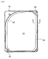
- a hard disk drive case in accordance with the embodiment is formed from a rectangular cover 12, which is a press-formed article of a metal plate as shown in plan view of Fig. 1 , and a box-shaped main body (not shown) assembled with the cover 12.
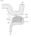
- a flange 14 having a predetermined height is formed on an outer circumferential portion of the cover 12, as shown in Figs. 1 and 2 .
- a recessed portion 16 is formed to escape from an unillustrated main body of the hard disk device.
- a flat gasket forming surface 18 is formed at the cover 12 between the flange 14 and the recessed portion 16. In the four corners of the cover 12, circular holes 20 through which screws used for mounting the cover 12 to the main body pass are formed.
- An elastic gasket 22 is formed on the gasket forming surface 18.
- the gasket 22 is formed from a hardening material (referred to as a gasket agent 24, hereinafter), which is originally in a liquid state having viscosity and can hardened (with elasticity as a gasket, however) or can be hardened after extruded to form the gasket 22.
- a gasket agent 24 a hardening material
- gasket agent 24 a gasket material disclosed in JP-A No. 2003-7047 can be used, for example. Other gasket agents may be also used.
- the gasket agent 24 in the embodiment is a material which is hardened with ultraviolet irradiation.
- a liquid gasket material is extruded with an extrusion port being moved by means of a three-dimensional automatic coating device in order to form the gasket 22 on the gasket forming surface 18.
- the embodiment is different from the conventional example in a point that the extrusion port is moved for one circuit along the periphery of the cover 12 (single stroke without passing through the same place again) to form the gasket in the conventional example while the extrusion port is moved for plural circuits in the embodiment.
- the gasket forming surface 18 is faced upward as shown in Fig. 3A while the liquid gasket agent 24 is extruded onto the gasket forming surface.
- the gasket agent 24 is arranged to be in contact with an inner side surface 14A of the flange 14.
- the height "h" of a portion where the gasket agent 24 and the inner side surface 14A are in contact is set lower than the height H of the flange (a dimension from the gasket forming surface 18 to an upper end of the flange 14).
- an extrusion of the second circuit is continuously conducted following the first circuit.
- the extrusion of the second circuit is conducted onto an extruded portion from the first circuit.
- the gasket agent 24 is arranged to be in contact with the inner side surface 14A of the flange 14 while the height "h" of the portion where the gasket agent 24 is in contact with the inner side surface 14A is set lower than the height H of the flange, as shown in Fig. 3B .
- the gasket agent 24 is doubly piled in the embodiment. Accordingly, the height of the gasket agent 24 after the two circuits can be set higher than the height H of the flange 14.
- the height "h" of the portion where the gasket agent 24 is in contact with the inner side surface 14A in the first circuit is set lower than the height H of the flange 14, as described above. Accordingly, the height is stable even when the gasket agent 24 is extruded for the second circuit continuously.
- a main body 26 is faced and screwed with respect to the cover 12 on which the gasket 22 is formed, as shown in Fig. 2 , whereby the cover 12 is mounted to the main body 26.
- a convex portion 28 of the main body 26 then abuts with the gasket 22 to compress the gasket 22 (a double-dashed line in Fig. 2 shows a position of the convex portion 28 at the time of the completion of the assembly), such that the inside of the hard disk drive case is sealed.
- the cover 12 and the main body 26 are displaced in a state where the gasket 22 is in contact with the main body 26 before screwing for the purpose of positioning the circular holes 20 of the cover 12 and holes (not shown) of the main body 26.
- a lateral (parallel to the gasket forming surface 18) force acts on the gasket 22.
- a side portion of the gasket 22 is fixed to the inner side surface 14A of the flange 14 at most of the periphery of the gasket 22 in the embodiment. Accordingly, it is difficult to peel off the gasket 22 from the gasket forming surface 18 even when the lateral force acts on the gasket 22.
- the gasket 22 in accordance with the embodiment can thus prevent a sealing defect caused by the peeling-off of the gasket 22 from occurring.
- a part of the gasket 22 is not in contact with the flange 14. This is not a matter, however, since it is confirmed in advance by an experiment or the like that the gasket 22 does not be peeled off when the lateral force acts.
- the height of the gasket 22 is preferably set within a range of 0.1 to 5.0 mm. This is for the purpose of preventing the case from occurring that the gasket agent 24 flows or the width thereof increases before the liquid gasket agent 24 is hardened, and consequently the shape at the time of coating cannot be maintained.
- the ratio A/B of the height A of the gasket 22 to the width B of the gasket 22 is preferably set within a range of 0.5 to 5.0. This is for the purpose of preventing the case from occurring that the gasket agent 24 flows or the width thereof increases before the liquid gasket agent 24 is hardened, and consequently the shape at the time of coating cannot be maintained.
- the extrusion port is moved continuously for two circuits to pile the gasket agent 24 on the gasket forming surface in the embodiment.
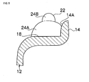
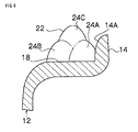
- the invention is not limited to the above. It may be possible to harden the gasket agent 24 which is extruded by moving the extrusion port in the first circuit, and further extrude the gasket agent 24 in the second circuit onto the hardened gasket agent 24 of the first circuit to harden the gasket agent 24 of the second circuit, as shown in Figs. 4 and 5 (a reference numeral 24A indicates the gasket material of the first circuit while a reference numeral 24B indicates the gasket material of the second circuit).
- the number of the circuits carried out by the extrusion port is not limited to two. It may be three or more.
- a reference numeral 24C indicates the gasket material of the third circuit
- a reference numeral 24D indicates the gasket material of the fourth circuit
- a reference numeral 24E indicates the gasket material of the fifth circuit
- a reference numeral 24F indicates the gasket material of the sixth circuit
- the gasket agent 24 is adhered to the side surface of the flange in the first circuit in the embodiment. It may be possible, however, to adhere the gasket agent 24 to the side surface of the flange in the second or the following circuits without adhering the gasket agent 24 to the side surface of the flange in the first circuit.
- the gasket agent 24 is extruded for two or more circuits to form the gasket 22 in the embodiment. Only one circuit (single stroke), however, may contribute to form the gasket 22 as long as the gasket agent 24 has high viscosity and the height of the gasket can be achieved.
- the invention is applied to a use which requires preventing a gasket from peeling off during assembly.
Landscapes
- Engineering & Computer Science (AREA)
- General Engineering & Computer Science (AREA)
- Mechanical Engineering (AREA)
- Gasket Seals (AREA)
- Extrusion Moulding Of Plastics Or The Like (AREA)
Claims (7)
- Verfahren zur Herstellung einer Dichtung (22), die eine Dichtung zum Abdichten eines Abstands zwischen einem ersten Konstruktionsteil und einem zweiten Konstruktionsteil bildet, wobei:ein Flanschteil (14), das von einer Abdichtungsfläche (18) irgend eines des ersten Konstruktionsteils und des zweiten Konstruktionsteils aufsteigt, an einer Außenseite der Abdichtungsfläche gebildet wird; und wenn kontinuierlich ein flüssiges härtendes Harz (24) mit Bezug auf die Abdichtungsfläche unter Bildung der Dichtung extrudiert wird, das härtende Harz in einem ersten Extrusionsschritt kontinuierlich auf die Abdichtungsfläche extrudiert wird, derart, dass ein Teil des extrudierten härtenden Harzes sich in Kontakt mit einer Seitenfläche (14A) des Flanschteils befindet unddadurch gekennzeichnet, dass die Gesamthöhe (h) des Teils des extrudierten härtenden Harzes in Kontakt mit dem Flanschteil niedriger ist als die Höhe (H) des Flanschteils und in einem darauffolgenden Schritt das härtende Harz kontinuierlich auf das extrudierte härtende Harz extrudiert wird, derart, dass das Harz sich in Kontakt mit der Seitenfläche des Flanschteils befindet und die Gesamthöhe des Teils des extrudierten härtenden Harzes in Kontakt mit dem Flanschteil niedriger ist als die Höhe des Flanschteils.
- Verfahren zur Herstellung einer Dichtung (22), die eine Dichtung zum Abdichten eines Abstands zwischen einem ersten Konstruktionsteil und einem zweiten Konstruktionsteil bildet, wobei:ein Flanschteil (14), das von einer Abdichtungsfläche (18) irgendeines des ersten Konstruktionsteils und des zweiten Konstruktionsteils aufsteigt, an einer Außenseite der Abdichtungsfläche gebildet wird; und
dadurch gekennzeichnet, dass, wenn kontinuierlich flüssiges härtendes Harz (24) mit Bezug auf die Abdichtungsfläche unter Bildung der Dichtung extrudiert wird, das härtende Harz in einem ersten Extrusionsschritt kontinuierlich auf die Abdichtungsfläche extrudiert wird, derart, dass das Harz sich nicht in Kontakt mit einer Seitenfläche (14A) des Flanschteils befindet und in einem darauffolgenden Extrusionsschritt das härtende Harz kontinuierlich auf das extrudierte härtende Harz extrudiert wird, derart, dass ein Teil des extrudierten Harzes sich in Kontakt mit der Seitenfläche des Flanschteils befindet und die Gesamthöhe des Teils des extrudierten härtenden Harzes, der sich in Kontakt mit dem Flanschteil befindet, niedriger ist als die Höhe des Flanschteils. - Verfahren zur Herstellung einer Dichtung nach Anspruch 1 oder 2, wobei das flüssige härtende Harz des Weiteren auf das in einem vorherigen Extrusionsschritt extrudierte flüssige härtende Harz extrudiert wird.
- Verfahren zur Herstellung einer Dichtung nach Anspruch 1 oder 2, wobei das flüssige härtende Harz, das in einem vorherigen Extrusionsschritt extrudiert worden ist, gehärtet wird und dann das flüssige härtende Harz auf das gehärtete flüssige härtende Harz extrudiert wird.
- Verfahren zur Herstellung einer Dichtung nach einem der Ansprüche 1 bis 4, wobei die Höhe der Dichtung innerhalb eines Bereichs von 0,1 bis 5,0 mm eingestellt wird.
- Verfahren zur Herstellung einer Dichtung nach einem der Ansprüche 1 bis 5, wobei ein Verhältnis A/B der Höhe A der Dichtung zu einer Breite B der Dichtung innerhalb eines Bereichs von 0,5 bis 5,0 eingestellt wird.
- Abdichtstruktur, die eine Dichtung aufweist, die durch das Verfahren zur Herstellung einer Dichtung nach einem der Ansprüche 1 bis 6 gebildet wird.
Applications Claiming Priority (2)
| Application Number | Priority Date | Filing Date | Title |
|---|---|---|---|
| JP2005315042A JP4787596B2 (ja) | 2005-10-28 | 2005-10-28 | ガスケットの製造方法、及びシール構造 |
| PCT/JP2006/321549 WO2007049763A1 (ja) | 2005-10-28 | 2006-10-27 | ガスケットの製造方法、及びシール構造 |
Publications (3)
| Publication Number | Publication Date |
|---|---|
| EP1950474A1 EP1950474A1 (de) | 2008-07-30 |
| EP1950474A4 EP1950474A4 (de) | 2012-03-21 |
| EP1950474B1 true EP1950474B1 (de) | 2013-08-21 |
Family
ID=37967871
Family Applications (1)
| Application Number | Title | Priority Date | Filing Date |
|---|---|---|---|
| EP06822510.1A Not-in-force EP1950474B1 (de) | 2005-10-28 | 2006-10-27 | Verfahren zur herstellung einer dichtung und dichtungsstruktur |
Country Status (5)
| Country | Link |
|---|---|
| US (1) | US20090243233A1 (de) |
| EP (1) | EP1950474B1 (de) |
| JP (1) | JP4787596B2 (de) |
| CN (1) | CN101300440B (de) |
| WO (1) | WO2007049763A1 (de) |
Families Citing this family (5)
| Publication number | Priority date | Publication date | Assignee | Title |
|---|---|---|---|---|
| FI121974B (fi) * | 2007-05-14 | 2011-06-30 | Flaekt Woods Ab | Menetelmä ilmanvaihtokanavien ja/tai niiden päätelaitteiden välisen tiivisteen muodostamiseksi sekä tiiviste |
| US8251030B2 (en) | 2009-07-23 | 2012-08-28 | Briggs & Stratton Corporation | Rocker cover system |
| DE102010063313A1 (de) * | 2010-12-17 | 2012-06-21 | Robert Bosch Gmbh | Axialscheibe für eine Zahnradpumpe und Zahnradpumpe mit einer solchen Axialscheibe |
| CN104324866B (zh) * | 2013-07-22 | 2016-05-11 | 泰科电子(上海)有限公司 | 在工件的凹槽中注入密封胶的方法 |
| US20150145384A1 (en) * | 2013-11-25 | 2015-05-28 | Motorola Solutions, Inc. | Apparatus and method for providing a seal around a perimeter of a bi-material enclosure |
Family Cites Families (10)
| Publication number | Priority date | Publication date | Assignee | Title |
|---|---|---|---|---|
| FR2411692A1 (fr) * | 1977-12-16 | 1979-07-13 | Seima | Procede pour la realisation de joints d'etancheite sur les feux ou projecteurs de vehicules automobiles ou analogues ou pour tout assemblage etanche de deux pieces |
| JPS60237267A (ja) * | 1984-05-09 | 1985-11-26 | Suriibondo:Kk | 複合成形物の成形方法 |
| DE3606011A1 (de) * | 1986-02-25 | 1987-09-17 | Heinz Konrad Prof Dr I Mueller | Extrusionssteifer dichtring |
| JPH08159288A (ja) * | 1994-11-30 | 1996-06-21 | Minnesota Mining & Mfg Co <3M> | シール材用成形部材及び該シール材用成形部材を使用するシール方法 |
| JPH11346064A (ja) * | 1998-06-01 | 1999-12-14 | Nec Corp | 装置の筐体の防水構造 |
| JP2001280507A (ja) * | 2000-03-29 | 2001-10-10 | Bridgestone Corp | シール材、シール材製造用型、並びに、シール用複合体及びその製造方法 |
| JP4139944B2 (ja) | 2002-02-26 | 2008-08-27 | Nok株式会社 | ガスケット |
| US20050206093A1 (en) * | 2002-03-28 | 2005-09-22 | Bridgestone Corporation | Method of manufacturing gasket for hard disk device and gasket |
| JP4244926B2 (ja) * | 2002-09-12 | 2009-03-25 | Nok株式会社 | ガスケット |
| JP2004108533A (ja) * | 2002-09-20 | 2004-04-08 | Nok Corp | ガスケット |
-
2005
- 2005-10-28 JP JP2005315042A patent/JP4787596B2/ja not_active Expired - Fee Related
-
2006
- 2006-10-27 EP EP06822510.1A patent/EP1950474B1/de not_active Not-in-force
- 2006-10-27 CN CN2006800403985A patent/CN101300440B/zh not_active Expired - Fee Related
- 2006-10-27 US US12/091,672 patent/US20090243233A1/en not_active Abandoned
- 2006-10-27 WO PCT/JP2006/321549 patent/WO2007049763A1/ja not_active Ceased
Also Published As
| Publication number | Publication date |
|---|---|
| CN101300440A (zh) | 2008-11-05 |
| US20090243233A1 (en) | 2009-10-01 |
| EP1950474A1 (de) | 2008-07-30 |
| JP4787596B2 (ja) | 2011-10-05 |
| CN101300440B (zh) | 2013-02-13 |
| EP1950474A4 (de) | 2012-03-21 |
| JP2007120661A (ja) | 2007-05-17 |
| WO2007049763A1 (ja) | 2007-05-03 |
Similar Documents
| Publication | Publication Date | Title |
|---|---|---|
| EP1533549B1 (de) | Dichtung | |
| US7959161B2 (en) | Rubber-like elastic part | |
| US9791893B2 (en) | Electronic device and method of assembling the electronic device | |
| CA2990143C (en) | Process for production of gaskets | |
| JP2010062232A (ja) | 素子の機能部を露出させた半導体装置の製造方法 | |
| WO2017002579A1 (ja) | 基板一体型ガスケットの製造方法 | |
| JPWO2016031511A1 (ja) | 電子制御装置 | |
| US10588230B2 (en) | Waterproof lid, electronic device, and manufacturing method for waterproof lid | |
| DE102007019096A1 (de) | Elektronikgehäuse | |
| JP6768822B2 (ja) | ガスケット及びその製造方法 | |
| EP1950474A1 (de) | Verfahren zur herstellung einer dichtung und dichtungsstruktur | |
| EP2146373A2 (de) | Anordnung mit einem Leistunghalbleitermodul und Verfahren zu deren Herstellung | |
| JP3865024B2 (ja) | ガスケット | |
| US9575380B2 (en) | Display panel including wiring protection pattern and display device | |
| JP2012018629A (ja) | Icタグ及びその製造方法 | |
| JP2008216780A (ja) | 表示素子の製造方法 | |
| US20220334617A1 (en) | Display device and manufacturing method of the same | |
| EP2761652B1 (de) | Verfahren zur herstellung einer lötverbindung | |
| WO2013125759A1 (ko) | 인쇄회로기판 패널 | |
| JP2005215050A (ja) | 液晶表示装置の製法 | |
| JP2001160279A (ja) | Hdd用ガスケット付カバー | |
| CN112285978B (zh) | 液晶显示面板的制作方法2 | |
| KR101237287B1 (ko) | 인쇄회로기판 패널 | |
| JP2004289943A (ja) | ガスケット及びその製造方法 | |
| KR100444231B1 (ko) | 인쇄회로기판의 절연층 형성방법 |
Legal Events
| Date | Code | Title | Description |
|---|---|---|---|
| PUAI | Public reference made under article 153(3) epc to a published international application that has entered the european phase |
Free format text: ORIGINAL CODE: 0009012 |
|
| 17P | Request for examination filed |
Effective date: 20080502 |
|
| AK | Designated contracting states |
Kind code of ref document: A1 Designated state(s): DE FR GB |
|
| DAX | Request for extension of the european patent (deleted) | ||
| RBV | Designated contracting states (corrected) |
Designated state(s): DE FR GB |
|
| A4 | Supplementary search report drawn up and despatched |
Effective date: 20120222 |
|
| RIC1 | Information provided on ipc code assigned before grant |
Ipc: F16J 15/14 20060101AFI20120216BHEP Ipc: F16L 21/035 20060101ALI20120216BHEP Ipc: B29C 65/02 20060101ALI20120216BHEP Ipc: F16J 15/06 20060101ALI20120216BHEP Ipc: F24F 13/02 20060101ALI20120216BHEP Ipc: F16J 15/10 20060101ALI20120216BHEP |
|
| 17Q | First examination report despatched |
Effective date: 20120918 |
|
| GRAP | Despatch of communication of intention to grant a patent |
Free format text: ORIGINAL CODE: EPIDOSNIGR1 |
|
| RIN1 | Information on inventor provided before grant (corrected) |
Inventor name: URANAKA, MASAKI C/O BRIDGESTONE CORPORATION |
|
| GRAS | Grant fee paid |
Free format text: ORIGINAL CODE: EPIDOSNIGR3 |
|
| GRAA | (expected) grant |
Free format text: ORIGINAL CODE: 0009210 |
|
| AK | Designated contracting states |
Kind code of ref document: B1 Designated state(s): DE FR GB |
|
| REG | Reference to a national code |
Ref country code: GB Ref legal event code: FG4D |
|
| REG | Reference to a national code |
Ref country code: DE Ref legal event code: R096 Ref document number: 602006038031 Country of ref document: DE Effective date: 20131017 |
|
| PLBE | No opposition filed within time limit |
Free format text: ORIGINAL CODE: 0009261 |
|
| STAA | Information on the status of an ep patent application or granted ep patent |
Free format text: STATUS: NO OPPOSITION FILED WITHIN TIME LIMIT |
|
| 26N | No opposition filed |
Effective date: 20140522 |
|
| REG | Reference to a national code |
Ref country code: DE Ref legal event code: R097 Ref document number: 602006038031 Country of ref document: DE Effective date: 20140522 |
|
| REG | Reference to a national code |
Ref country code: FR Ref legal event code: CA Effective date: 20140812 |
|
| REG | Reference to a national code |
Ref country code: FR Ref legal event code: PLFP Year of fee payment: 10 |
|
| PGFP | Annual fee paid to national office [announced via postgrant information from national office to epo] |
Ref country code: DE Payment date: 20151022 Year of fee payment: 10 Ref country code: GB Payment date: 20151021 Year of fee payment: 10 |
|
| PGFP | Annual fee paid to national office [announced via postgrant information from national office to epo] |
Ref country code: FR Payment date: 20151023 Year of fee payment: 10 |
|
| REG | Reference to a national code |
Ref country code: DE Ref legal event code: R119 Ref document number: 602006038031 Country of ref document: DE |
|
| GBPC | Gb: european patent ceased through non-payment of renewal fee |
Effective date: 20161027 |
|
| REG | Reference to a national code |
Ref country code: FR Ref legal event code: ST Effective date: 20170630 |
|
| PG25 | Lapsed in a contracting state [announced via postgrant information from national office to epo] |
Ref country code: FR Free format text: LAPSE BECAUSE OF NON-PAYMENT OF DUE FEES Effective date: 20161102 Ref country code: DE Free format text: LAPSE BECAUSE OF NON-PAYMENT OF DUE FEES Effective date: 20170503 Ref country code: GB Free format text: LAPSE BECAUSE OF NON-PAYMENT OF DUE FEES Effective date: 20161027 |