EP1943452B1 - Agencement de piston, en particulier pour vannes de dosage - Google Patents
Agencement de piston, en particulier pour vannes de dosage Download PDFInfo
- Publication number
- EP1943452B1 EP1943452B1 EP06791711A EP06791711A EP1943452B1 EP 1943452 B1 EP1943452 B1 EP 1943452B1 EP 06791711 A EP06791711 A EP 06791711A EP 06791711 A EP06791711 A EP 06791711A EP 1943452 B1 EP1943452 B1 EP 1943452B1
- Authority
- EP
- European Patent Office
- Prior art keywords
- piston
- chamber
- housing
- outlet opening
- injector
- Prior art date
- Legal status (The legal status is an assumption and is not a legal conclusion. Google has not performed a legal analysis and makes no representation as to the accuracy of the status listed.)
- Active
Links
- 238000007789 sealing Methods 0.000 claims abstract description 21
- 230000006835 compression Effects 0.000 claims description 23
- 238000007906 compression Methods 0.000 claims description 23
- 239000012530 fluid Substances 0.000 claims description 23
- 230000033001 locomotion Effects 0.000 claims description 14
- 238000006073 displacement reaction Methods 0.000 claims description 2
- 230000001105 regulatory effect Effects 0.000 claims description 2
- 239000011796 hollow space material Substances 0.000 claims 4
- 230000000284 resting effect Effects 0.000 claims 2
- 239000004519 grease Substances 0.000 description 13
- 238000005461 lubrication Methods 0.000 description 8
- 238000004891 communication Methods 0.000 description 4
- 239000000314 lubricant Substances 0.000 description 4
- 101000579647 Penaeus vannamei Penaeidin-2a Proteins 0.000 description 1
- 230000000903 blocking effect Effects 0.000 description 1
- 238000010276 construction Methods 0.000 description 1
- 230000000694 effects Effects 0.000 description 1
- 238000011156 evaluation Methods 0.000 description 1
- 230000001050 lubricating effect Effects 0.000 description 1
- 238000012423 maintenance Methods 0.000 description 1
- 238000005259 measurement Methods 0.000 description 1
- 230000003287 optical effect Effects 0.000 description 1
- 238000011144 upstream manufacturing Methods 0.000 description 1
Images


Classifications
-
- F—MECHANICAL ENGINEERING; LIGHTING; HEATING; WEAPONS; BLASTING
- F16—ENGINEERING ELEMENTS AND UNITS; GENERAL MEASURES FOR PRODUCING AND MAINTAINING EFFECTIVE FUNCTIONING OF MACHINES OR INSTALLATIONS; THERMAL INSULATION IN GENERAL
- F16N—LUBRICATING
- F16N25/00—Distributing equipment with or without proportioning devices
- F16N25/02—Distributing equipment with or without proportioning devices with reciprocating distributing slide valve
Definitions
- the invention relates to a piston arrangement with which, for example, a metering valve, a flow sensor or a hydraulic motor can be realized.
- a metering valve which has two piston-containing cylinder.
- a piston In the upstream cylinder, a piston is arranged. Further, a cylinder rod is provided, wherein the downward movement of the piston is transmitted to the second piston via the piston rod, so that the second piston moves down accordingly.
- a metering piston which is suitable for forwarding a defined amount of fluid, and to provide a reversing piston, which causes a reciprocating movement of the metering.
- a piston assembly should not only be simple and space-saving as possible in construction, but also be permanently reliable in their function.
- a piston assembly which comprises a housing in which at least one cylindrical cavity is formed, in which a first piston is sealed and slidably mounted and in which at least partially a cylindrical cavity is formed and has a second piston, which in the cylindrical cavity of the first piston is slidably mounted.
- a valve seat should be formed in the first piston, against which the second piston with a sealing surface can be applied so that the second piston in the first piston between a flow passage through the first piston releasing and a flow passage through the first piston blocking position is displaceable.
- the first piston thus acts as a metering piston, by the movement of which a defined amount of a fluid, in particular a lubricant, can be conveyed or metered.
- the second piston acts against it together with other components, such as a spring or the like, as a reversing piston, which change by selectively opening and / or closing the pressure acting on the first piston and thus can cause a reversal of the direction of movement of the first piston. Since the two pistons are arranged in one another, it is possible to keep the dimensions of the piston arrangement according to the invention particularly compact. Further, this simple structure of the piston assembly achieves low maintenance intensity and high reliability of the piston assembly.
- the second piston is associated with an elastic element, in particular a cup spring assembly or a compression spring, such that the second piston is acted upon in the direction of its one flow passage by the first piston releasing position.
- an elastic element in particular a cup spring assembly or a compression spring
- a smooth seal between the first and the second valve which also achieves a good sealing effect, can be realized in that the valve seat and the sealing surface are conical.
- the seal can be improved by providing the valve seat and / or the sealing surface with a sealing element, for example a sealing ring.
- the second piston at least partially has a cylindrical outer surface whose diameter corresponds approximately to the inner diameter of the cylindrical cavity of the first piston, according to the invention on the outer surface of the second piston helical grooves can be provided so that a fluid in these grooves between the first and the second Piston can flow along.
- the piston assembly is part of a metering valve in which the first piston defines as injector piston in the housing two chambers, which can be brought into fluid communication with each other by displacement of the second piston or against each other.
- the surface of the first and second piston facing the first chamber is smaller than the surface of the first piston facing the second chamber and, if appropriate, elements connected thereto.
- This difference in area makes it possible to control the movement of the piston assembly by first passing fluid through the piston assembly so that the pistons are then displaced against the flow direction of the fluid due to the larger effective area in the second chamber. If, on the other hand, the second piston seals the passage in the first piston, the pistons will be displaced by the fluid in the opposite direction, i.
- the housing preferably forms an injector body which can be connected to a distributor strip, in which a first opening for connecting the first chamber to a supply line in the distributor strip and an outlet opening closable, in particular via an overflow valve, which in turn is provided with a discharge opening Distributor rail provided connection is connected.
- a distributor strip in which a first opening for connecting the first chamber to a supply line in the distributor strip and an outlet opening closable, in particular via an overflow valve, which in turn is provided with a discharge opening Distributor rail provided connection is connected.
- the outlets of the respective injectors are located on the distributor strip.
- a repair or replacement of an injector should be necessary, so only fixing screws or the like of the injector concerned must be solved and be removed.
- the fixed piping on the distribution board and the distribution board itself remain mounted so that the system is very easy to maintain. It can also be realized distribution strips, which accommodate several injectors. As a result, only the dimension of the distribution strip and the number of connection holes changes. Unused injector
- an injector closure screw in which in turn a regulation, for example with a screw, is screwed, wherein optionally in the regulation associated with the first piston indicator pin is guided displaceably.
- the stroke of the injector piston and thus, for example, the Dosierfettmenge is limited by the stop on the Injektorver gleichschraube. If, for example, a smaller amount of grease is required, then a set screw in the regulation can be infinitely adjusted so that a display pin connected to the first piston strikes mechanically and thus limits the piston stroke. As a result, it is theoretically also possible to set a zero delivery for the metering valve according to the invention.
- the second chamber is connectable to the environment of the housing via a sealable by means of a screw plug opening.
- a sealable by means of a screw plug opening By such, for example, side openings a plurality of injectors can be interconnected, whereby the flow rate per stroke and lubrication point can be increased without using injectors with a larger maximum flow rate.
- the two chambers should be sealed against each other, wherein the resulting gap is acted upon by a discharge line with a lower pressure than the pressure in the main line.
- This can be done by having the first and the second Chamber are sealed against each other via the first piston, wherein in this sealing region of the first piston, an opening is provided in the housing, which is in flow communication with the outlet opening or with the environment of the housing.
- the piston assembly is part of a flow sensor, wherein the housing for connection in a fluid line an inlet opening and an outlet opening, between which the first piston is arranged, has. Between the inlet opening and the first piston there is formed a first chamber and between the outlet opening and the first piston a second chamber, which communicate with each other or are separated from each other depending on the position of the second piston in the first piston.
- the second piston which forms a control valve, together with a compression spring, the first piston serving as a sensor piston can be set into an oscillating motion when the inlet opening is pressurized. This can be detected by a sensor and sent to a controller and evaluated.
- the flow sensor according to the invention is designed particularly space-saving and reliable.
- the second piston is preferably associated with a compression spring which is supported on the first piston or on a component connected thereto and acts on the second piston in the direction of its position connecting the two chambers. This facilitates, for example, together with the fluid force opening the passage between the first and second piston.
- a further compression spring acting on the first piston in the direction of the inlet opening is provided.
- These Compression spring is designed such that the first piston is displaceable in the closed second piston by the fluid pressure against the force of this further compression spring towards the outlet opening. If the second piston then abuts against a corresponding surface of the outlet opening with a stop, the second piston is also opened by the force of the pressure spring acting thereon so that fluid can flow from the inlet opening through the piston arrangement to the outlet opening. In this state, the further compression spring pushes the first piston back toward the inlet opening, with the passage opening in the piston arrangement closing again in this case. This results in a detectable oscillating movement of the piston assembly.
- the measurement of a flow rate can be realized by simple means that on or in the first piston, for example, a magnet, in particular a ring magnet is provided, wherein on or in the housing, a sensor, in particular a Hall sensor, for detecting the position and / or the movement of the magnet or the like is provided. In this way it is possible to detect whether a fluid flows through the flow sensor. With known volume, which flows through the flow sensor at a stroke of the piston assembly according to the invention, also the flow rate can be determined.
- the Hall sensor or the like may be provided on a circuit board, which additionally carries function LEDs and connection cable. Preferably, the board is potted and mounted on the housing of the flow sensor.
- the piston assembly is part of a hydraulic motor.
- the first piston may be formed as a differential piston with a surface difference as in a metering valve (injector) and extended to the outside.
- injector injector
- Each metering valve or injector shown in each case consist of an injector body or housing 4, wherein in the embodiment shown, three injector bodies 4 are fastened on a common distributor strip 9, each with two cylinder head screws 10.
- the seal between the Injektor stresses 4 and the distribution bar 9 by means of O-rings, as shown in the sectional view of 3 and 4 is apparent.
- the assembly of the complete distribution unit, which consists of the distribution bar and the injectors, can be done for example via two located in the distribution bar 9 mounting holes.
- the supply of lubricant into the distributor unit is effected by a feed line 16, which is designed as a through-bore in the distributor strip 9 with lateral connection threads for screw-in screw connections for connecting the pump line or further distributor strips.
- the outlets of the individual injectors are returned to the distribution bar 9 and can be connected via straight (or angled) Einschraubverschraubonne 12 to lubrication lines that lead, for example, to a storage location.
- Each individual injector (metering valve) consists of the injector body 4 (housing), in which a first piston is located as an injector piston 8 with attachments.
- An injector plug 3 closes the injector on the in the Fig. 1 and 3 upper side and represents a stroke limiter for the injector piston assembly.
- a regulation 1 is screwed, by means of which the metered amount can be influenced.
- a viewing window is formed in the regulation, in which a display pen 2 can be seen, which is connected to the first piston 8 and moves with it during a lubrication cycle up and down.
- the injector piston 8 defines in the injector body 4 a first chamber 14, which faces the distributor bar 9, and one of these applied second chamber 15.
- the first chamber 14 is in flow communication with the supply line 16.
- the second chamber 15 is provided with a lateral outlet, which in the illustrated embodiment is closed with a closure screw 11.
- branches off from the second chamber 15 further from an outlet hole 17 through which a lubricant is passed to the Einschraubverschraubung 12 in the distribution bar 9.
- an overflow valve 13 is provided in the illustrated embodiment, which consists of a ball, a spring and a spring holder.
- a second piston 7 is slidably guided, which forms a control valve.
- This in Fig. 3 lower end of the injector piston 8 is provided with a conical valve seat 18, while the lower end of the second piston 7 has a corresponding conical sealing surface 19 with a sealing ring.
- a cylindrical outer surface region of the second piston 7 is provided with a helically arranged groove, so that between the outer surface of the second piston 7 and the likewise cylindrical inner surface of the first piston 8, a fluid can flow when the sealing surface 19 is lifted from the valve seat 18.
- a helical compression spring 6 is tensioned, which urges the second piston 7 in its open position.
- a plate spring package may be provided.
- the charging phase begins when the control valve 7 (second piston) in the pressureless state by the spring force of the helical compression spring 6 in the injector piston 8 (first piston) is opened. If, for example, fat is pumped by means of a grease pump through the supply line 16 into the first chamber 14 of the injector, the grease flows past the open control valve 7 past the helical groove and thus passes through the injector piston 8 into the second chamber 15. From this, the grease flows further into the outlet bore 17 to before the initially closed overflow valve 13. With further fat delivery into the injector increases the internal pressure, which is due to the differences in surface area on the injector piston 8 due to the resulting force in Fig. 3 moves down. In this phase, the second chamber 15 is filled with grease.
- the control valve 7 closes by mechanical stop on the bottom of the hole in the injector body 4 (housing).
- the presentation of the Fig. 3 shows the end of the charging phase, in which the control valve 7 is already closed again.
- the pressure when the grease pump continues to promote fat or the like in the injector increases in the first chamber 14 and in relation to it in the second chamber 15, the pressure when the grease pump continues to promote fat or the like in the injector. If, in the second chamber 14 and thus also in the outlet bore 17, the pressure set at the overflow valve 13 is exceeded, this opens and the injector piston 8 can be pushed in by the pressure in the first chamber 14 Fig. 3 be pushed up. The grease contained in the second chamber 15 is thereby conveyed through the outlet bore 17 on the overflow valve 13 over to a bearing or the like.
- This dosing phase is followed by the unloading phase in order to start a new lubrication cycle again with a loading phase.
- the pressure in the supply line 16 must drop below the dimensioned relief pressure of preferably approximately 90 bar. If the relief pressure falls below the control valve 7 is opened by the force of the compression spring 6. The pending pressure from the supply line 16 in the first chamber 14 immediately relaxes into the second chamber 15 and causes a small downward movement of the injector piston 8. The discharge rate of the main line is increased by the piston stroke during unloading, as taken in this piston stroke of the supply line 16 grease becomes.
- the flow sensor 20 has an inlet opening 21a which can be integrated into a fluid line and an outlet opening 21b which can likewise be integrated into a fluid line.
- the inlet opening 21a and the outlet opening 21b close a tubular sensor housing 22 and are sealed with respect to this by means of O-rings.
- the inlet opening 21a and the outlet opening 21b are provided with an internal thread, so that a straight screwed connection can be mounted in them.
- a first piston 23 (sensor piston) is displaceably guided, so that two chambers in the housing 22 are defined by the sensor piston 23 between the inlet port 21 a and the outlet port 21 b.
- a second piston 24 (sensor control valve) is displaceably guided, wherein in the sensor piston 23 and the sensor control valve 24 as described above, a conical valve seat and a corresponding sealing surface are formed. Further, the cylindrical outer surface of the second piston 24 is provided with a helical groove, so that a fluid can flow through this groove between the first and second piston.
- the second piston 24 is by a conical compression spring 25, which is supported on a received in the sensor piston 23 ring magnet 26, in the direction of its in Fig. 5 left, open position applied. Further, a compression spring 27 is provided between the sensor piston 23 and the outlet port 21 b, which also the sensor piston 23 in Fig. 5 applied to the left.
- a molded circuit board with a Hall sensor 28, function LEDs and a connection cable On the sensor housing 22 is a molded circuit board with a Hall sensor 28, function LEDs and a connection cable.
- the flow sensor may for example be installed in the grease inlet of a lubrication point to monitor the grease supply.
- the spring 27 presses the sensor piston assembly in Fig. 5 to the left in the direction of the inlet opening 21a. until the sensor control valve 24 is closed by mechanical stop at the inlet port 21a.
- a flow through the flow sensor according to the invention thus causes an oscillating movement of the sensor piston 23 and the associated with this ring magnet 26 in the sensor housing 22.
- the movement of the magnetic field can be detected by the Hall sensor 28 and forwarded to a controller for evaluation.
- the switching of the Hall sensor 28 can thereby be displayed optically by means of an LED. Another LED can provide information about the operating status of the flow sensor. In this way, it is possible to determine the transit times or the delivery volume per unit time by a grease feed line with the detected signal.
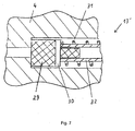
- Fig. 7 is considered an alternative to that in Fig. 4 shown overflow valve 13 with ball and spring an overflow valve 13 'with a sealing member 29 from eg. PUR with a support disk 30 and a spring 31 shown.
- a clamping sleeve 32 serves to limit the stroke and protects the spring 31 from overloading, since the block length of the spring 31 is not reached.
Landscapes
- Engineering & Computer Science (AREA)
- General Engineering & Computer Science (AREA)
- Mechanical Engineering (AREA)
- Measuring Volume Flow (AREA)
- Reciprocating Pumps (AREA)
- Indication Of The Valve Opening Or Closing Status (AREA)
- Lubrication Of Internal Combustion Engines (AREA)
- Fluid-Driven Valves (AREA)
- Closures For Containers (AREA)
Claims (13)
- Agencement de pistons, en particulier pour des soupapes de dosage, des capteurs de débit ou des moteurs hydrauliques, dotés d'un carter (4, 22), dans lequel est formée au moins une cavité cylindrique, dans laquelle un premier piston (8, 23) est monté de façon étanchéifiée et coulissante, qui présente au moins par endroits une cavité cylindrique, et d'un second piston (7, 24), qui est logé de façon coulissante dans la cavité cylindrique du premier piston (8, 23), un siège de soupape étant réalisé dans le premier piston (8, 23), siège contre lequel le second piston (7, 24) peut être appliqué avec une surface d'étanchéité de telle sorte que le second piston (7, 24) peut coulisser dans le premier piston (8, 23) entre une position libérant un passage d'écoulement à travers le premier piston (8, 23) et une position bloquant un passage d'écoulement dans le premier piston (8, 23), caractérisé en ce qu'un élément élastique, en particulier un ressort de pression ou un ensemble de ressort à disque (6, 25) est attribué au second piston (7, 24) de telle sorte que le second piston (7, 24) est sollicité dans sa position libérante un passage d'écoulement dans le premier piston (8, 23).
- Agencement de pistons selon la revendication 1, caractérisé en ce que le siège de soupape et la surface d'étanchéité sont conçus dans une forme conique.
- Agencement de pistons selon l'une quelconque des revendications 1 à 2, caractérisé en ce que le second piston (7, 24) présente au moins par endroits une surface extérieure cylindrique, dont le diamètre correspond à peu près au diamètre intérieur, de la cavité cylindrique du premier piston (8, 23) et sur laquelle des rainures de forme héliocoïdale sont prévues.
- Soupape de dosage dotée d'un agencement de pistons selon l'une quelconque des revendications 1 à 3, caractérisée en ce que le premier piston (8) en tant que piston injecteur définit dans le carter (4) deux chambres (14, 15) qui peuvent être amenées en liaison d'écoulement l'une avec l'autre par déplacement du second piston (7), la surface, tournée vers la première chambre (14), du premier et du second pistons (7, 8) étant inférieure à la surface, tournée vers la seconde chambre (15), du premier piston (8) et d'éléments (2, 5) éventuellement reliés à ce piston.
- Soupape de dosage selon la revendication 4, caractérisée en ce que le carter (4) forme un corps injecteur pouvant être relié à une réglette de distribution (9), dans lequel il présente une première ouverture pour la liaison de la première chambre (14) avec une arrivée dans la réglette de distribution (9) et une ouverture de sortie pouvant être fermée en particulier par une soupape de trop-plein (13), laquelle ouverture est reliée à son tour à un raccordement (12) prévu dans la réglette de distribution (9).
- Soupape de dosage selon la revendication 4 ou 5, caractérisée en ce qu'une vis de fermeture d'injecteur (3) est vissée dans le carter (4) sur le côté de la seconde chambre (15), vis dans laquelle est vissée une vis de régulation (1), dans laquelle éventuellement une pointe d'affichage reliée au premier piston (8) est guidée de façon coulissante.
- Soupape de dosage selon l'une quelconque des revendications 4 à 6, caractérisée en ce que la seconde chambre (15) peut être reliée par une ouverture pouvant être étanchéifiée au moyen d'une vis de fermeture (11) à l'environnement du carter (4).
- Soupape de dosage selon l'une quelconque des revendications 4 à 7, caractérisée en ce que la première et la seconde chambres (14, 15) sont étanchéifiées l'une par rapport à l'autre au moyen du premier piston (8) et en ce qu'il est prévu dans la zone d'étanchéité du premier piston (8) une ouverture dans le carter (4) qui est en liaison d'écoulement avec l'ouverture de sortie ou avec l'environnement du carter (4).
- Capteur de débit doté d'un agencement de pistons selon l'une quelconque des revendications 1 à 3, caractérisé en ce que le carter (22) présente pour le raccordement dans une conduite de fluide une ouverture d'entrée (21a) et une ouverture de sortie (21b), entre lesquelles le premier piston (23) est disposé, une première chambre étant formée entre l'ouverture d'entrée (21a) et le premier piston (23) et une seconde chambre entre l'ouverture de sortie (21b) et le premier piston (23), lesquelles sont en liaison l'une avec l'autre ou sont séparées l'une de l'autre en fonction de la position du second piston (24) dans le premier piston (23).
- Capteur de débit selon la revendication 9, caractérisé en ce qu'un ressort de pression (25) s'appuyant sur le premier piston (23) ou un composant (26) relié à ce piston est associé au second piston (24), lequel ressort sollicite le second piston (24) en direction de sa position reliant les deux chambres.
- Capteur de débit selon la revendication 9 ou 10, caractérisé en ce qu'un autre ressort de pression (27) sollicitant le premier piston (23) en direction de l'ouverture d'entrée (21a) est prévu entre l'ouverture de sortie (21b) et le premier piston (23).
- Capteur de débit selon l'une quelconque des revendications 9 à 11, caractérisé en ce qu'un aimant, en particulier un aimant annulaire (26), est prévu sur ou dans le premier piston (23) et en ce qu'un capteur (28), en particulier un capteur de Hall, est prévu sur ou dans le carter (22) pour l'enregistrement de la position et/ou du déplacement de l'aimant (26).
- Moteur hydraulique doté d'un agencement de pistons selon l'une quelconque des revendications 1 à 3, le carter (22) présentant pour le raccordement dans une conduite de fluide une ouverture d'entrée (21a) et une ouverture de sortie (21b), entre lesquelles le premier piston (23) est disposé, une première chambre étant formée entre l'ouverture d'entrée (21a) et le premier piston (23) et une seconde chambre entre l'ouverture de sortie (21b) et le premier piston (23), lesquelles chambres sont en liaison l'une avec l'autre ou séparées l'une de l'autre en fonction de la position du second piston (24) dans le premier piston (23), un ressort de pression (25) s'appuyant sur le premier piston (23) ou un composant (26) relié à ce piston étant attribué au second piston (24), lequel ressort sollicite le second piston (24) en direction de sa position reliant les deux chambres, et un autre ressort de pression (27) sollicitant le premier piston (23) en direction de l'ouverture d'entrée (21a) étant prévu entre l'ouverture de sortie (21b) et le premier piston (23).
Applications Claiming Priority (2)
| Application Number | Priority Date | Filing Date | Title |
|---|---|---|---|
| DE202005017065U DE202005017065U1 (de) | 2005-10-28 | 2005-10-28 | Kolbenanordnung, insbesondere für Zumessventile |
| PCT/EP2006/008446 WO2007048460A1 (fr) | 2005-10-28 | 2006-09-26 | Agencement de piston, en particulier pour vannes de dosage |
Publications (3)
| Publication Number | Publication Date |
|---|---|
| EP1943452A1 EP1943452A1 (fr) | 2008-07-16 |
| EP1943452B1 true EP1943452B1 (fr) | 2010-03-03 |
| EP1943452B8 EP1943452B8 (fr) | 2010-05-19 |
Family
ID=36062621
Family Applications (1)
| Application Number | Title | Priority Date | Filing Date |
|---|---|---|---|
| EP06791711A Active EP1943452B8 (fr) | 2005-10-28 | 2006-09-26 | Agencement de piston, en particulier pour vannes de dosage |
Country Status (9)
| Country | Link |
|---|---|
| US (1) | US8136634B2 (fr) |
| EP (1) | EP1943452B8 (fr) |
| AT (1) | ATE459841T1 (fr) |
| AU (1) | AU2006308269B2 (fr) |
| CA (1) | CA2627448A1 (fr) |
| DE (2) | DE202005017065U1 (fr) |
| EA (1) | EA013343B1 (fr) |
| WO (1) | WO2007048460A1 (fr) |
| ZA (1) | ZA200804520B (fr) |
Families Citing this family (13)
| Publication number | Priority date | Publication date | Assignee | Title |
|---|---|---|---|---|
| DE202006007591U1 (de) * | 2006-05-12 | 2007-06-21 | Bopp & Reuther Messtechnik Gmbh | Ventilvorrichtung zum Druckausgleich |
| DE202006016377U1 (de) * | 2006-10-20 | 2007-02-01 | Lincoln Gmbh | Schmiermittelverteiler |
| DE102012217452B4 (de) * | 2012-09-26 | 2015-05-07 | Skf Lubrication Systems Germany Gmbh | Schmierstoffverteiler für die Abgabe von Schmierstoff an mindestens eine Schmierstelle sowie Verfahren zum Betrieb desselben |
| CN104180141B (zh) * | 2014-08-13 | 2016-09-07 | 绍兴县滨海塑料制品厂 | 节油型润滑装置 |
| PL3026178T3 (pl) * | 2014-11-27 | 2019-05-31 | Srt Soc A Responsabilita Limitata Con Unico Socio | Podbijarka torowa do podsypki kolejowej |
| IT201600100783A1 (it) * | 2016-10-07 | 2018-04-07 | Dropsa Spa | Impianto di distribuzione di lubrificante semisolido e metodo di controllo di tale impianto |
| DE102017200481A1 (de) * | 2017-01-13 | 2018-07-19 | Skf Lubrication Systems Germany Gmbh | Schmierstoffverteilsystem und Verfahren zu seinem Betrieb |
| NL2020053B1 (nl) * | 2017-12-11 | 2019-06-19 | N V Nederlandsche Apparatenfabriek Nedap | Melkmeter |
| CN108426159B (zh) * | 2018-03-30 | 2023-06-23 | 安徽工程大学 | 一种稳压装置及具有其的集中润滑系统 |
| GB2584490A (en) * | 2019-06-07 | 2020-12-09 | Oxford Flow Ltd | Position sensor for a fluid flow control device |
| DE102020204240A1 (de) * | 2020-04-01 | 2021-10-07 | Sms Group Gmbh | Wächter für Handschmierstellen an rotierenden oder bewegten Bauteilen und System sowie Verfahren zur Überwachung von Abschmiervorgängen an Handschmierstellen |
| US11835176B2 (en) * | 2020-07-02 | 2023-12-05 | Lsp Industries, Inc. | Lubricating system |
| EP4350195A1 (fr) * | 2022-10-04 | 2024-04-10 | DROPSA S.p.A. | Dispositif de dosage de lubrifiant |
Family Cites Families (8)
| Publication number | Priority date | Publication date | Assignee | Title |
|---|---|---|---|---|
| US2000925A (en) * | 1929-08-26 | 1935-05-14 | Union Bank Of Chicago | Lubricant discharge valve for forcefeed lubricating systems |
| US3233628A (en) * | 1962-12-24 | 1966-02-08 | Hammelmann Paul | Hydraulic device for the automatic actuation of a piston |
| US3581845A (en) | 1969-03-07 | 1971-06-01 | Ingersoll Rand Co | Air line oiler |
| US3587782A (en) | 1969-03-07 | 1971-06-28 | Olin Mathieson | Automatic fluid injector |
| US3715013A (en) | 1971-08-19 | 1973-02-06 | Eaton Corp | Lubricant injector |
| US3958725A (en) | 1974-10-15 | 1976-05-25 | Auto Research Corporation | Metering valve for lubrication injector |
| US4096747A (en) * | 1975-10-14 | 1978-06-27 | Gilson Paul R | Digital output, positive displacement flow meter |
| JP3898149B2 (ja) * | 2003-04-25 | 2007-03-28 | ファナック株式会社 | 定量分配器 |
-
2005
- 2005-10-28 DE DE202005017065U patent/DE202005017065U1/de not_active Expired - Lifetime
-
2006
- 2006-09-26 US US12/091,842 patent/US8136634B2/en active Active
- 2006-09-26 AU AU2006308269A patent/AU2006308269B2/en not_active Ceased
- 2006-09-26 DE DE502006006355T patent/DE502006006355D1/de active Active
- 2006-09-26 EP EP06791711A patent/EP1943452B8/fr active Active
- 2006-09-26 WO PCT/EP2006/008446 patent/WO2007048460A1/fr active Application Filing
- 2006-09-26 EA EA200801057A patent/EA013343B1/ru not_active IP Right Cessation
- 2006-09-26 CA CA002627448A patent/CA2627448A1/fr not_active Abandoned
- 2006-09-26 AT AT06791711T patent/ATE459841T1/de active
-
2008
- 2008-05-23 ZA ZA200804520A patent/ZA200804520B/xx unknown
Also Published As
| Publication number | Publication date |
|---|---|
| DE202005017065U1 (de) | 2006-03-02 |
| AU2006308269A1 (en) | 2007-05-03 |
| EP1943452B8 (fr) | 2010-05-19 |
| US20090193965A1 (en) | 2009-08-06 |
| ATE459841T1 (de) | 2010-03-15 |
| ZA200804520B (en) | 2009-06-24 |
| WO2007048460A1 (fr) | 2007-05-03 |
| DE502006006355D1 (de) | 2010-04-15 |
| EP1943452A1 (fr) | 2008-07-16 |
| AU2006308269B2 (en) | 2011-07-07 |
| EA200801057A1 (ru) | 2008-10-30 |
| WO2007048460A8 (fr) | 2008-07-31 |
| EA013343B1 (ru) | 2010-04-30 |
| CA2627448A1 (fr) | 2007-05-03 |
| US8136634B2 (en) | 2012-03-20 |
Similar Documents
| Publication | Publication Date | Title |
|---|---|---|
| EP1943452B1 (fr) | Agencement de piston, en particulier pour vannes de dosage | |
| EP0825348B1 (fr) | Amplificateur de pression de fluide, particulièrement de fluide hydraulique | |
| DE2709386A1 (de) | In einer richtung wirkender durchflussbegrenzer | |
| DE2348387A1 (de) | Druckabhaengige fluid-ventilanordnung | |
| DE19529168A1 (de) | Hydraulischer Türschließer und Verfahren zum Herstellen desselben | |
| DE102013108940A1 (de) | Eigenmedium gesteuertes Ringkolbenventil | |
| EP1779023B1 (fr) | Distributeur de dechargement | |
| DE4224973C2 (de) | Fluidversorgungssystem mit Druckbegrenzung | |
| EP2218957B1 (fr) | Distributeur de lubrifiant | |
| DE10145200B4 (de) | Türschließer | |
| DE2821528A1 (de) | Durchflussfuehler | |
| EP1001196B1 (fr) | Soupape de limitation de pression, en particulier pour des véhicules | |
| DE102012103636B4 (de) | Bidirektionales Durchflusssteuerventil | |
| EP0637711B1 (fr) | Vanne pour fluides | |
| CH656228A5 (de) | Druckmesseinrichtung mit einem druckfuehler. | |
| EP2565468B1 (fr) | Agencement de vannes | |
| DE19923422C2 (de) | Elektronisches Einspritzsystem | |
| EP0281126B1 (fr) | Dispositif pour mesurer ou doser des matériaux fluides | |
| DE19524777B4 (de) | Türschließer mit einstellbarer Vorspannung einer Schließerfeder | |
| CH661333A5 (en) | Pressure-operated valve device | |
| DE602004003141T2 (de) | Zumesseinrichtung | |
| EP2132443B1 (fr) | Pompe avec une soupape de commande à commande magnétique pour l'étranglement de l'aspiration | |
| DE19833106C1 (de) | Pumpenschutzarmatur | |
| DE3415863A1 (de) | Schaltgeraet fuer zweileitungs-zentralschmieranlagen | |
| DE3146938A1 (de) | "druckverhaeltnis-ventil fuer einen hydraulik-kreislauf" |
Legal Events
| Date | Code | Title | Description |
|---|---|---|---|
| PUAI | Public reference made under article 153(3) epc to a published international application that has entered the european phase |
Free format text: ORIGINAL CODE: 0009012 |
|
| 17P | Request for examination filed |
Effective date: 20080423 |
|
| AK | Designated contracting states |
Kind code of ref document: A1 Designated state(s): AT BE BG CH CY CZ DE DK EE ES FI FR GB GR HU IE IS IT LI LT LU LV MC NL PL PT RO SE SI SK TR |
|
| 17Q | First examination report despatched |
Effective date: 20090116 |
|
| GRAP | Despatch of communication of intention to grant a patent |
Free format text: ORIGINAL CODE: EPIDOSNIGR1 |
|
| DAX | Request for extension of the european patent (deleted) | ||
| GRAS | Grant fee paid |
Free format text: ORIGINAL CODE: EPIDOSNIGR3 |
|
| GRAA | (expected) grant |
Free format text: ORIGINAL CODE: 0009210 |
|
| AK | Designated contracting states |
Kind code of ref document: B1 Designated state(s): AT BE BG CH CY CZ DE DK EE ES FI FR GB GR HU IE IS IT LI LT LU LV MC NL PL PT RO SE SI SK TR |
|
| REG | Reference to a national code |
Ref country code: GB Ref legal event code: FG4D Free format text: NOT ENGLISH |
|
| REG | Reference to a national code |
Ref country code: CH Ref legal event code: EP |
|
| REG | Reference to a national code |
Ref country code: IE Ref legal event code: FG4D |
|
| REF | Corresponds to: |
Ref document number: 502006006355 Country of ref document: DE Date of ref document: 20100415 Kind code of ref document: P |
|
| RAP2 | Party data changed (patent owner data changed or rights of a patent transferred) |
Owner name: LINCOLN GMBH |
|
| REG | Reference to a national code |
Ref country code: NL Ref legal event code: VDEP Effective date: 20100303 |
|
| PG25 | Lapsed in a contracting state [announced via postgrant information from national office to epo] |
Ref country code: LT Free format text: LAPSE BECAUSE OF FAILURE TO SUBMIT A TRANSLATION OF THE DESCRIPTION OR TO PAY THE FEE WITHIN THE PRESCRIBED TIME-LIMIT Effective date: 20100303 |
|
| LTIE | Lt: invalidation of european patent or patent extension |
Effective date: 20100303 |
|
| PG25 | Lapsed in a contracting state [announced via postgrant information from national office to epo] |
Ref country code: LV Free format text: LAPSE BECAUSE OF FAILURE TO SUBMIT A TRANSLATION OF THE DESCRIPTION OR TO PAY THE FEE WITHIN THE PRESCRIBED TIME-LIMIT Effective date: 20100303 Ref country code: PL Free format text: LAPSE BECAUSE OF FAILURE TO SUBMIT A TRANSLATION OF THE DESCRIPTION OR TO PAY THE FEE WITHIN THE PRESCRIBED TIME-LIMIT Effective date: 20100303 Ref country code: SI Free format text: LAPSE BECAUSE OF FAILURE TO SUBMIT A TRANSLATION OF THE DESCRIPTION OR TO PAY THE FEE WITHIN THE PRESCRIBED TIME-LIMIT Effective date: 20100303 Ref country code: FI Free format text: LAPSE BECAUSE OF FAILURE TO SUBMIT A TRANSLATION OF THE DESCRIPTION OR TO PAY THE FEE WITHIN THE PRESCRIBED TIME-LIMIT Effective date: 20100303 |
|
| REG | Reference to a national code |
Ref country code: IE Ref legal event code: FD4D |
|
| PG25 | Lapsed in a contracting state [announced via postgrant information from national office to epo] |
Ref country code: NL Free format text: LAPSE BECAUSE OF FAILURE TO SUBMIT A TRANSLATION OF THE DESCRIPTION OR TO PAY THE FEE WITHIN THE PRESCRIBED TIME-LIMIT Effective date: 20100303 Ref country code: ES Free format text: LAPSE BECAUSE OF FAILURE TO SUBMIT A TRANSLATION OF THE DESCRIPTION OR TO PAY THE FEE WITHIN THE PRESCRIBED TIME-LIMIT Effective date: 20100614 Ref country code: EE Free format text: LAPSE BECAUSE OF FAILURE TO SUBMIT A TRANSLATION OF THE DESCRIPTION OR TO PAY THE FEE WITHIN THE PRESCRIBED TIME-LIMIT Effective date: 20100303 Ref country code: CY Free format text: LAPSE BECAUSE OF FAILURE TO SUBMIT A TRANSLATION OF THE DESCRIPTION OR TO PAY THE FEE WITHIN THE PRESCRIBED TIME-LIMIT Effective date: 20100303 Ref country code: IE Free format text: LAPSE BECAUSE OF FAILURE TO SUBMIT A TRANSLATION OF THE DESCRIPTION OR TO PAY THE FEE WITHIN THE PRESCRIBED TIME-LIMIT Effective date: 20100303 Ref country code: GR Free format text: LAPSE BECAUSE OF FAILURE TO SUBMIT A TRANSLATION OF THE DESCRIPTION OR TO PAY THE FEE WITHIN THE PRESCRIBED TIME-LIMIT Effective date: 20100604 Ref country code: SE Free format text: LAPSE BECAUSE OF FAILURE TO SUBMIT A TRANSLATION OF THE DESCRIPTION OR TO PAY THE FEE WITHIN THE PRESCRIBED TIME-LIMIT Effective date: 20100303 Ref country code: RO Free format text: LAPSE BECAUSE OF FAILURE TO SUBMIT A TRANSLATION OF THE DESCRIPTION OR TO PAY THE FEE WITHIN THE PRESCRIBED TIME-LIMIT Effective date: 20100303 |
|
| PG25 | Lapsed in a contracting state [announced via postgrant information from national office to epo] |
Ref country code: BG Free format text: LAPSE BECAUSE OF FAILURE TO SUBMIT A TRANSLATION OF THE DESCRIPTION OR TO PAY THE FEE WITHIN THE PRESCRIBED TIME-LIMIT Effective date: 20100603 Ref country code: SK Free format text: LAPSE BECAUSE OF FAILURE TO SUBMIT A TRANSLATION OF THE DESCRIPTION OR TO PAY THE FEE WITHIN THE PRESCRIBED TIME-LIMIT Effective date: 20100303 Ref country code: IS Free format text: LAPSE BECAUSE OF FAILURE TO SUBMIT A TRANSLATION OF THE DESCRIPTION OR TO PAY THE FEE WITHIN THE PRESCRIBED TIME-LIMIT Effective date: 20100703 Ref country code: CZ Free format text: LAPSE BECAUSE OF FAILURE TO SUBMIT A TRANSLATION OF THE DESCRIPTION OR TO PAY THE FEE WITHIN THE PRESCRIBED TIME-LIMIT Effective date: 20100303 |
|
| PLBE | No opposition filed within time limit |
Free format text: ORIGINAL CODE: 0009261 |
|
| STAA | Information on the status of an ep patent application or granted ep patent |
Free format text: STATUS: NO OPPOSITION FILED WITHIN TIME LIMIT |
|
| PG25 | Lapsed in a contracting state [announced via postgrant information from national office to epo] |
Ref country code: PT Free format text: LAPSE BECAUSE OF FAILURE TO SUBMIT A TRANSLATION OF THE DESCRIPTION OR TO PAY THE FEE WITHIN THE PRESCRIBED TIME-LIMIT Effective date: 20100705 Ref country code: DK Free format text: LAPSE BECAUSE OF FAILURE TO SUBMIT A TRANSLATION OF THE DESCRIPTION OR TO PAY THE FEE WITHIN THE PRESCRIBED TIME-LIMIT Effective date: 20100303 |
|
| 26N | No opposition filed |
Effective date: 20101206 |
|
| BERE | Be: lapsed |
Owner name: LINCOLN G.M.B.H. Effective date: 20100930 |
|
| PG25 | Lapsed in a contracting state [announced via postgrant information from national office to epo] |
Ref country code: MC Free format text: LAPSE BECAUSE OF NON-PAYMENT OF DUE FEES Effective date: 20100930 |
|
| REG | Reference to a national code |
Ref country code: CH Ref legal event code: PL |
|
| GBPC | Gb: european patent ceased through non-payment of renewal fee |
Effective date: 20100926 |
|
| REG | Reference to a national code |
Ref country code: FR Ref legal event code: ST Effective date: 20110531 |
|
| PG25 | Lapsed in a contracting state [announced via postgrant information from national office to epo] |
Ref country code: LI Free format text: LAPSE BECAUSE OF NON-PAYMENT OF DUE FEES Effective date: 20100930 Ref country code: CH Free format text: LAPSE BECAUSE OF NON-PAYMENT OF DUE FEES Effective date: 20100930 Ref country code: BE Free format text: LAPSE BECAUSE OF NON-PAYMENT OF DUE FEES Effective date: 20100930 Ref country code: FR Free format text: LAPSE BECAUSE OF NON-PAYMENT OF DUE FEES Effective date: 20100930 |
|
| PG25 | Lapsed in a contracting state [announced via postgrant information from national office to epo] |
Ref country code: GB Free format text: LAPSE BECAUSE OF NON-PAYMENT OF DUE FEES Effective date: 20100926 |
|
| PG25 | Lapsed in a contracting state [announced via postgrant information from national office to epo] |
Ref country code: LU Free format text: LAPSE BECAUSE OF NON-PAYMENT OF DUE FEES Effective date: 20100926 Ref country code: HU Free format text: LAPSE BECAUSE OF FAILURE TO SUBMIT A TRANSLATION OF THE DESCRIPTION OR TO PAY THE FEE WITHIN THE PRESCRIBED TIME-LIMIT Effective date: 20100904 |
|
| PG25 | Lapsed in a contracting state [announced via postgrant information from national office to epo] |
Ref country code: TR Free format text: LAPSE BECAUSE OF FAILURE TO SUBMIT A TRANSLATION OF THE DESCRIPTION OR TO PAY THE FEE WITHIN THE PRESCRIBED TIME-LIMIT Effective date: 20100303 |
|
| REG | Reference to a national code |
Ref country code: DE Ref legal event code: R082 Ref document number: 502006006355 Country of ref document: DE Representative=s name: KEIL & SCHAAFHAUSEN PATENT- UND RECHTSANWAELTE, DE |
|
| REG | Reference to a national code |
Ref country code: DE Ref legal event code: R081 Ref document number: 502006006355 Country of ref document: DE Owner name: SKF LUBRICATION SYSTEMS GERMANY GMBH, DE Free format text: FORMER OWNER: LINCOLN GMBH, 69190 WALLDORF, DE Effective date: 20141202 Ref country code: DE Ref legal event code: R082 Ref document number: 502006006355 Country of ref document: DE Representative=s name: KEIL & SCHAAFHAUSEN PATENT- UND RECHTSANWAELTE, DE Effective date: 20141202 |
|
| PGFP | Annual fee paid to national office [announced via postgrant information from national office to epo] |
Ref country code: AT Payment date: 20150921 Year of fee payment: 10 |
|
| PGFP | Annual fee paid to national office [announced via postgrant information from national office to epo] |
Ref country code: IT Payment date: 20150924 Year of fee payment: 10 |
|
| REG | Reference to a national code |
Ref country code: AT Ref legal event code: MM01 Ref document number: 459841 Country of ref document: AT Kind code of ref document: T Effective date: 20160926 |
|
| PG25 | Lapsed in a contracting state [announced via postgrant information from national office to epo] |
Ref country code: IT Free format text: LAPSE BECAUSE OF NON-PAYMENT OF DUE FEES Effective date: 20160926 Ref country code: AT Free format text: LAPSE BECAUSE OF NON-PAYMENT OF DUE FEES Effective date: 20160926 |
|
| P01 | Opt-out of the competence of the unified patent court (upc) registered |
Effective date: 20230514 |
|
| PGFP | Annual fee paid to national office [announced via postgrant information from national office to epo] |
Ref country code: DE Payment date: 20230928 Year of fee payment: 18 |