US2000925A - Lubricant discharge valve for forcefeed lubricating systems - Google Patents
Lubricant discharge valve for forcefeed lubricating systems Download PDFInfo
- Publication number
- US2000925A US2000925A US388323A US38832329A US2000925A US 2000925 A US2000925 A US 2000925A US 388323 A US388323 A US 388323A US 38832329 A US38832329 A US 38832329A US 2000925 A US2000925 A US 2000925A
- Authority
- US
- United States
- Prior art keywords
- valve
- piston
- casing
- spring
- intake
- Prior art date
- Legal status (The legal status is an assumption and is not a legal conclusion. Google has not performed a legal analysis and makes no representation as to the accuracy of the status listed.)
- Expired - Lifetime
Links
- 239000000314 lubricant Substances 0.000 title description 30
- 230000001050 lubricating effect Effects 0.000 title description 5
- 239000012530 fluid Substances 0.000 description 31
- 230000006835 compression Effects 0.000 description 3
- 238000007906 compression Methods 0.000 description 3
- 239000003921 oil Substances 0.000 description 3
- 101100001675 Emericella variicolor andJ gene Proteins 0.000 description 1
- 241001178521 Sarotherodon caroli Species 0.000 description 1
- AVKUERGKIZMTKX-NJBDSQKTSA-N ampicillin Chemical compound C1([C@@H](N)C(=O)N[C@H]2[C@H]3SC([C@@H](N3C2=O)C(O)=O)(C)C)=CC=CC=C1 AVKUERGKIZMTKX-NJBDSQKTSA-N 0.000 description 1
- 230000003190 augmentative effect Effects 0.000 description 1
- 230000015572 biosynthetic process Effects 0.000 description 1
- 238000010276 construction Methods 0.000 description 1
- 238000007599 discharging Methods 0.000 description 1
- 239000007788 liquid Substances 0.000 description 1
- 238000003754 machining Methods 0.000 description 1
- 238000004519 manufacturing process Methods 0.000 description 1
- 239000011345 viscous material Substances 0.000 description 1
Images


Classifications
-
- F—MECHANICAL ENGINEERING; LIGHTING; HEATING; WEAPONS; BLASTING
- F16—ENGINEERING ELEMENTS AND UNITS; GENERAL MEASURES FOR PRODUCING AND MAINTAINING EFFECTIVE FUNCTIONING OF MACHINES OR INSTALLATIONS; THERMAL INSULATION IN GENERAL
- F16N—LUBRICATING
- F16N27/00—Proportioning devices
Definitions
- invention relates to improvements vin -dis .chaise valves Afor.,.rtree-.feecllubricating, systems L wherein lubricant Ais'idischarged ⁇ -flltm-l a pump through piping .to bearings etc; tto belubrifier-ted, ⁇
- the main objectA of v,the present invention 4 is to. provide a valve el? the. aforesaid time which 'veil-l operate .connection with .a pump wherein .the .n pressure is lgraclua'lly built up from zero to the desired p nt e her b vslcvv movement of. :the
- a furtherl object of Vthe invention Vls to provide a valveaf the tvne speeiiied whiohis vveii adapted for use insvsterns wherein lubricant 'of Vhigh viscosity such .as Ygrease asdistinguished from the morey fluent oils..l v r In .the accompanying td-ravvinssil 'Lablezembediments of thenventieni
- n Fig-l is ⁇ a eentral longitudinal seeticni oie valve-structure embodying .the :invention v.showins the movable valvefstructure membersy thereofin .normal position.
- n Fie. 2 is a similar :View :showing ,saidfmovfable valve members at the other limit .of their'movenient; Y i
- Fia :3 is .a similar view showing the'movable valve vmembers relative positions inmediately following release .0i pump pressure and preparatory .te .return of saidvalve roetfilters' t0 initial position.l y Y y n n Fig; 4. is a perspective view 0i the piston elementof the structurelof Fissi to I Figs. .5, 6, and 1 .arevievvs similar to Figs. 1.2, and .3, respectively, 'illustrating .another exnhodiment of the invention.
- Y the piston elementof the structurelof Fissi to I Figs. .5, 6, and 1 .arevievvs similar to Figs. 1.2, and .3, respectively, 'illustrating .another exnhodiment of the invention.
- Fig. 8 is .a perspectiveview ci .the valve associated with the. piston elements of the structures .of Figs. 1 to 3, and 5 to 7. respecti-velv.Y Fig. 9 ,is a perspective. View of the piston element of Figs. 5 to 7 inclusive.
- Figs. 1.0, ,1.1, and .1.2 are views similar to Figs. 1. .2. and 3, ⁇ respectively illustrating still another yernlcmiznent of the invention.V l
- Figl isaI perspective view ofV th bei' of Figs. l0, 11, 'and' 12; 1
- valvev I I is provided with a stem .I 2 Aextendj-ing axially through-the piston" Bandprovided -betvvenits ends With an annular ange I3.
- the type of pump used to introduce lubricant under pressure into the casing I may be an ordinary piston pump'having a free discharge port, i. e. a discharge port devoid of a check-valve or may be-pumps ci the types illustrated and described in mytcopending applications, Serial No. 98,886, led March 31, 1926; Serial No. 131,843, filed Aug. 27, 1926; and Serial No. 221,197, filed Sept. 28, 1927, oranyrother type wherein the piping pressure may be completely relieved following a discharge of lubricant under pressure.
- valve II being now open andfthe check- 'valve 'I being closed, it follows that during return travel of the piston to initial position, the flubricant in theintake end of the casing I Will pass through the piston 8 into the discharge end portion to provide the predetermined volume to be fed to the bearing at the next operation.
- Valves of this type are-usually screw-machine held check valve 21. 28 is of the same outer diameter throughout its 9 seats onv the shoulderV degree of skill and care on the part of the operator in charge, are not usually very accurate.
- This embodiment is, furthermore, better adapted for lubricants which vary considerably in fluidity, either under the inuence of variations in temperature or as between oils and greases, thus permitting changes in the type of lubricant used without necessitating Aa change in the discharge valve structure.
- the length-'of the larger diameter end portion of the piston may be increased or the length of the middle portion I of the casingY reduced so that by interchanging pistons 8 or casing members I, valves of varying capacities are produced at low cost.
- j Y The embodiment shown in Figs. 5 to 9 inclusive comprises the casing 22, whichdiifers from the casing of Fig. 1 only in that the small bore portion 3 is omitted, the bore 23 extending from the intakeport 25 to the small bore portion 24 leading to the discharge port 26 equipped with the spring-
- the hollow trunk piston length has the centralV opening bordered by the valve seat 29 on which the valve 30 seats.
- the latter and its stem 3I are of the same construction as is the valve II of Fig. 1, the stem being pro.- vided between its ends with the annularvflange 32 with which the springs 33 and 34 engage, the latter being the same as the spring I6 of Fig. 1 and the former corresponding to the spring I4.
- the discharge end area oi' the piston plus Wall rictional resistance to travel constitute the factors which cooperate with the spring 33 and the pressure of incoming lubricant to overcome the greater force of spring 34, While pressure of incoming lubricant on the area of the piston end bordering the valve seat 29 affords a factor cooperating with the spring 34 to open the valve 38 against the action of thespring 33.
- thislstructure theifcasing x35 iis .prcvide'dat :one vend with [a :closure :cap 1335' .having an fannular .externally l threaded iilang'eY 3.7l terminating in gan ,annularfzinitially:cylindrical lip 38.
- the iin'take "LportlS ⁇ ,is sflared at thezinnerlend :of the fcapwall ,and :is bordered by an zannular shoulder;- against .which ,the marginal ,.plortion ;of a screen 5,40 abuts. :Aiplug 45!
- the latter is A.provided ⁇ on itsiinner .face with a relatively .deep annular' groove llwliich normally receives the annular Jflange Muof Vthe valve 45.
- the latter .comprisesa atplaterhaving'a central stern 4,6 terminating in a l:prcn'ection M marginal 4portionof the valve l5 .sea-ts one endof .a'sleeve or hollow piston 1:8 .pro-
- vat Asaiclliencl with an inwardly .extendingfannula-lr' flange '49; the 'inner edge .of which isspaced from the stem w suiicientlyto accommodate the y inwardly ⁇ extending "flange V150 at'oneffend-iof a sheet 'meta-l sleeve 5l equipped .atjits other end with-an outwardly extending'innige,52.k
- ticularlywhenth'e lubricant ⁇ used is a very iiuent l .inthe structured. rigs 1 w3, the annular Y 'space between the flange 9 .of thepiston and The projection aref thestem 4s of the valve ment of the pistonin Vboth directions and coact-V ing with both springs I4 and I6 to maintain the valve l I closed during travel of thepiston toward the discharge port and to maintain said valve open during spring return movement of said piston.
- the spout'of the plug ⁇ 4l coacting with the ange 44 vof the valve 45 may alsoybe defined asa secondary uid pressure responsive means for insuring initial closure of said valveV 155. ⁇
- a machineor In use, a machineor a seriesof machines lhav-l or tubing with a single pump of a capacity greater than the aggregate capacities of all ofthe said valves.
- a lubricant may be fed fromthe pump at any desired pressure, the minimum of which must be Y sufficient to overcome the resistance of the several springs l5, 34, or 54, the springs of the rcheck valves at the discharge ends of rthe casings and the resistance offered -by the tightest bearing of the group fedby the pump.4V
- the maximum pressure of the lubricant may be asl high as the operator desires.
- a pump of the type shown in Fig. 1 ofthe drawings of Patent No. 1,652,764 may be used in connection with the above described discharge valves, said patent also illustrating aV suitable arrangement ofpiping connecting. the several valves with the discharge port of said pump.
- Any ordinary pump provided with a check valve controlled discharge port may also be used in connection with-the rvalves .shown and described and particularly in connection with the structure of Figs. lto 3,7but in such case the check valves controlling the discharge ports o-f the-valve cas- 'ings must be omitted.
- a valve of the type specified comprising a casing having a cylindrical bore and provided at opposite ends with intake and discharge ports,
- valve seat 'bordering one end of said passage and being opposed to the intake port of the casing, a valve controlling said passage and adapted to seat on said valve seat, a. spring arranged to maintain said valve normally closed, a second and more powerful spring arranged to maintain said valve open during absence' of Vfluid pressure thereon counter to said spring and to maintain saidrpiston normallyat the' intake end of said Y casing, v.the end wallr of the latterv bordering the intake port thereof constitutingA a stop limiting the travel of said valve under the infiuence of the more powerful spring to thereby cause'the first-mentioned springto seat said valve, and an annular shoulder in the discharge end portion of said casing on which said piston is adapted to seat to interrupt flow of lubricant from the vdischarge port of said casing as said piston is actuated against the action of the Amore powerful spring by fluid under pressure entering the intake port of said casing.
- a valve structure comprising a casing having intake and discharge ports at opposite ends.
- a piston reciprocable in said casing and provided withl a passage for fiuid therethrough, a valve seat'bordering one end of said passage and opposing said intake port, a valve adapted to'seat on said valve seat, a spring operatively associated with said valve to maintain the same normally closed to seal said passage, a more powerful spring associated withsaid valver and said casing for maintaining said valve open, asrthe piston is moved toward the intake end of said casing thereby, and means coacting with said valve and piston for interrupting discharge of fiuid from the discharge port of said casing as said piston attains a predeterminedposition in its discharge stroke under the influence of fluid under pressure entering the intake port of said casing.
- a valve Vof the vtype specified comprising a casing having a cylindrical bore and equipped at opposite ends with an intake port and a discharge port, a hollow piston reciprocable in said casing and ⁇ equipped with a valve seat opposed to the intake'port, a Valve adapted to seat on said valve seat, a spring arranged to maintain said valve normally closed, a second and more powerful spring opposed to said first-named spring and arranged to maintain the said valve open and move the piston toward the intake 'end of the casing in the absence of fluid pressure in the said end portion of said casing, means coacting with said valve and piston for interruptingA discharge of said fluid from the discharge port of said casing as said piston attains a predetermined 'position in its discharge stroke under the influence of fluid under pressure entering the intake port of said casing, the piston area opposed to said discharge port being greater than the area thereof opposed to the intake port.
- a valve structure comprising a casing having an intake port at one end and discharge port at its other end, apiston reciprocable in said casing and provided with a by-pass duct for the passage of fluid from the intake to the discharge end portions'of-the casing, a valve seat bordering one end.
- a valve adapted to seat on said valve seat, a spring engaged with said valve and said pistonv for normally maintaining said valve closedfa more powerful spring engaged with said valve for causing the same to open during travel of the piston toward the intake end portion of the casing and coacting with the rst-namedspring for maintaining said piston disposed at one limit of its movement, and means in the discharge end portion of the casing cooperating with said valve and piston for interrupting iow of fluid from the discharge port of said casing at a given point in the travel of said Vpiston responsively to fluid under pressure enter- 'a differential diameter piston reciprocable inrsaid casing and havingrespective end portions disposed and maintained in said corresponding portions'of the'casing during travel, a by-pass duct connecting the intake ⁇ end portion of the casing with vthe vdischarge end portion thereof, a nor- 4mally closed spring-held valve controlling said duct,la spring maintaining the piston normally as said piston moves toward-
- valve structure comprisingya casing, prov'videdg-with inlet and discharge ports at respecf.VV
- Witlrs fluid pressure resistance to travel ,of said piston.:in respectively opposite diF rections to .maintain saidvalve'closed as .said piston moves toward the discharge port responT sivelyAv to ⁇ fluid under Apressure entering the .intake i port ⁇ andato maintain thesaid'valve open during reverse travel ofgsaid piston;
- Avalve structure comprising ⁇ acasing having arrinlet and adischarge port, a piston reciproe cableinclsaid casing betweensaid ports, a by-pass duct throughr said piston, a valve controlling said duct," a pair of opposedA springslof respectively diierentzpower engaged'fwith: said valve, one ofv saidspringsbeing engaged with theA piston for normally maintaining said valveclosed and.
- a valve structure comprising -acasing'having an inlet and adischarge port, a piston reciprocaf ble'r in saidrcasing between said ports, ahy-,pass duct through said piston, avalve controllingsaid duct, a pair; of opposed springs ofrespectively dif ⁇ ferent povverengagedwith 'saidvalva one o'fsaid springs being engagedjwiththe' piston for normallymaintaining saidvalveclosedand co-operating with fluid under: pressure enteringjthe in-f takev port of said casing tojrnaintain'saidvalve closed during travel of vsaid'piston responsively to Y saiduid lunder pressure, the'otherof said springs being engaged with the casing and adapt'edto.;
- a valve structure c,om'prisingfa'lc'fzsinge,havev ing; anfinletwandia discharge -'port;a piston ref; ciprocable in saidcasing bem/,eensaidfportsarby@ ⁇ passV duct through, said-piston, al valve;controlling; ⁇ saidduct; a' pair of ,opposedtspringsf of :respective-g ly?, different :power:engagedl with .saidfvalva one'ofg' ⁇ saidL springs being engaged withfthepiston, for; '1 normally maintaining ,said valve'closed.
- a valve ofthe type specified comprising a casing having an intake andai discharge port, a reeiprocable member disposedv between saldi ports, a check-'Valvecontrolling one of said ports, said member being fluid-pressure responsive for travel in, one direction, a spring for .eifectin'g' travel thereof inthe other direction, uid presl sure means between said member and said casing' yfor resisting travel of said member in both directions, a by-pass duct through said member'arrangedto normally prevent flow of fluidthere ⁇ throughfrom the intake to the discharge end portion of said casing, said spring engaged with said valve and co-olperating with saidfluid ,pressureA means to open said valve uponrelief of the ud' 75' passage and adapted to be maintained closed by forvresisting fluid pressureresponsive vtravel of said member, a by-pass duct through the latter, a spring-held Anormally closed valve controlling said duct and 'engaged with said spring for opening by the latter,
- vA valveof the type speciiied comprising a casing having a cylindricalbore and provided at oppositel ends withintake and discharge ports, al
- a second and more powerful spring arranged to maintain said valve open during the return move-V ment of the piston after discharge stroke and to maintain said piston normally at the intake end Vof said casing, the end wall of the latter borderling the intake port thereofv constituting a stop limiting the travel'of said valve under the influence'of the more powerful spring to thereby cause the first-mentioned spring to seat said valve, and an annular shoulderin the discharge end portion of said casing on which said piston is adapted to seat to interrupt flowv of lubricant from the discharge port ofv said casing as said piston is ac tuated against' the action oi ⁇ the more powerful spring by -fiuidunder pressure entering the intake port of said casing.
- a lubricant supply valve comprising a casing equipped with an intake port at one end and a'discharge port at its other end, a piston reciprocable insaid casing and provided vwith a passage therethrough, a' valve controlling said uid under pressure entering the intake port of the casing and cause the piston to move toward the discharge port, a spring for maintaining said ,valve closed independently of fluidpressure, a more powerful spring engagedwith said valve and the dischargeend of the casing and opposed to the first-named spring and adapted to open said' valve and move said piston towardy the intake port upon relief of said fluid pressure and means in the discharge port end of said casing for limiting thetravel of said piston under the inuence of said fluid under pressure.
- a lubricant supply valver comprising a casing equipped at opposite ends with an intake and Y a discharge port respectively, a piston reciprocable between said ports and equippedl with a passage therethrough, a .valve arranged to close the end of said passage opposed to the intake port to prevent passage of inflowing fluid through said passage, a stop for limiting opening movement of said valve, a light spring engaged with said piston and said valve for maintaining the latter closed Vand a more powerful spring engaged with said valve in opposition to said first-mentioned spring and engaged with the discharge port end of the casing and acting to hold said valve en ⁇ stroke of said piston under the influence' of saidV spring.V Y
- vA lubricant supply valve comprising a casing equipped at opposite ends with an intake and a discharge port respectively, a check valve controlling said discharge port, a piston reciprocable between said ports and .equipped with a passage therethrough, a valve arranged to close the end of said passage opposed to the intake port to Vprevent passage of iniiowing fluid through vsaid passage, a stop for limiting opening movement of said valve, a light spring engagedY with said'piston and said valve for maintaining the latter closed and a more powerful spring engaged with said valve in opposition'v to said first-mentioned spring and engagedwith the discharge port end of the casing and acting to hold saidfvalve engaged normally with the intake end portion of the casing, said casing equipped with a stop formation for limiting travel of the piston toward the dischargeend of the casing as valve is moved in said direction against the action of the last named spring by fluid under pressureA entering the casing, said last-named spring acting to open said valve upon relief of said fluid pressure and maintain the same open during the
Landscapes
- Engineering & Computer Science (AREA)
- General Engineering & Computer Science (AREA)
- Mechanical Engineering (AREA)
- Safety Valves (AREA)
Description
' May 14, 1935. l. cQwLEs LUBRICANT DISCHARGE VALVEFOR FORGEFEED LUBRICATING SYSTEMS jf Q m W .TMA
E i E Filed Aug. 26, 1929 May 14, l1935. l. cowLES 2,000,925 LUBRICANT DISCHARGE VALVE FOR FORCEFEED LUBRICATING SYSTEMS Filed Aug. 2e, i929` s sheets-sheet 2 ,wf f ww )4d ,J f a we 0. y Y. mw M wb v\ n n n f May 14, 1935- I vl. cowLEs 2,000,925
y LUBRICANT DISCHARGE VALVE FOR FVORCEFEED JUBRICIJ.'ING SYSTEMS 'Filed Aug. 26, 1929 s sheets-sheet 5 Patented May 14', 1935 1 y ,LUBRICATING SYSTEMS IrvngCowlesfDeti-oit, Mich., assignor to Union' Y Bank of Chicago,V Chi 'v f of IllinoisLasjttustee i Application August 2.6,
" 17 claims.
-7 .invention relates to improvements vin -dis .chaise valves Afor.,.rtree-.feecllubricating, systems L wherein lubricant Ais'idischarged `-flltm-l a pump through piping .to bearings etc; tto belubrifier-ted,`
5 the-valve ef the present :invention being :adapted 'tey belfinterpcsed 'betweentle vbearing and the piping er tubing andeeperatite-tc automatically Elow 0f the luhrieanttothefbearing .after a stilo stantial-lylV predetermined Volume of' said i0 lubricant. has been discharged te said Ibeatriz-ig.
The main objectA of v,the present invention 4is to. provide a valve el? the. aforesaid time which 'veil-l operate .connection with .a pump wherein .the .n pressure is lgraclua'lly built up from zero to the desired p nt e her b vslcvv movement of. :the
pist. l.or an -termittcnt movement there.- `of, and which will also voperate Aefficiently fin -connecticn Ywith a pump wherein the -pressureis built 'lin to the desiredhish-ncin-t by a ver-v rapid move-- 20 .rient ci the piston as, tor yexample, wunder the inriluence .ci an actuating snr-ing. 1
A furtherl object of Vthe invention Vls to provide a valveaf the tvne speeiiied whiohis vveii adapted for use insvsterns wherein lubricant 'of Vhigh viscosity such .as Ygrease asdistinguished from the morey fluent oils..l v r In .the accompanying td-ravvinssil 'Lablezembediments of thenventieni n Fig-l is `a eentral longitudinal seeticni oie valve-structure embodying .the :invention v.showins the movable valvefstructure membersy thereofin .normal position. n Fie. 2 is a similar :View :showing ,saidfmovfable valve members at the other limit .of their'movenient; Y i
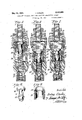
Fia :3 is .a similar view showing the'movable valve vmembers relative positions inmediately following release .0i pump pressure and preparatory .te .return of saidvalve roetfilters' t0 initial position.l y Y y n n Fig; 4. is a perspective view 0i the piston elementof the structurelof Fissi to I Figs. .5, 6, and 1 .arevievvs similar to Figs. 1.2, and .3, respectively, 'illustrating .another exnhodiment of the invention. Y
. Fig. 8 is .a perspectiveview ci .the valve associated with the. piston elements of the structures .of Figs. 1 to 3, and 5 to 7. respecti-velv.Y Fig. 9 ,is a perspective. View of the piston element of Figs. 5 to 7 inclusive. Figs. 1.0, ,1.1, and .1.2 are views similar to Figs. 1. .2. and 3, `respectively illustrating still another yernlcmiznent of the invention.V l
Figl, isaI perspective view ofV th bei' of Figs. l0, 11, 'and' 12; 1
lustrating s te valve mem- *valve-seat I0. 1 This spring acts cago, Ill., a corporation"- .V
19.29, 'serial No; 388,3.'3 "f (01.113477.) i n f n n VReferring new to Figs. 11nd 3 ineiusivgi be seen that the' valve .comprises a.;ca.sing l havjing an internal VsteppedV cylindrical'bore come prising a large.y diameter portion i2. and smaller diameter portions 3 andVV 4saidbores beinglaxfr lally aligned with eaohfotherl andf-Withithe intake port 5V and discharge port-IiiV respectively. -The latter is suitably equipped; witha spr-ingheld check-'valvel -V y v, fTheccasing mayV comprise the middle :or body `portion IV andtwo endginenibers .Ill-andai" as shown,` as this willpermit middle:portionsV ,I'sof vcentral opening is borderedby a valve#seatV Il) on Twhich the'valVeII is normally seated. The valvev I I is provided witha stem .I 2 Aextendj-ing axially through-the piston" Bandprovided -betvvenits ends With an annular ange I3. Y A' helical compression ,spring I4bears .at one-pend .f on the said ange V=I3 and at itsother endupon the annular shoulder I5 of the piston 8vbelow the f valveHII'normally seated. g l
k Another compression spring I6 h end upon the other face of the said ange .I3 and to maintain the 1 .L "30 earsy at `one at its other end upon the annularshoulder I1"r .bordering the `discharge portgILA j The .lastftmen- I vtioned .springis stronger than the firstmentioned sons hereinafter particularly .pointedY f one for' rea out. At :the lower end of the borel portion 2 isv an .annular shoulder I`8 constitutinga valve-seat; on :which .the anged end portion of the pistoni seats to interruptow from the intake end po1".'`
tion tothe discharge `endportion of the casing. "The trunk pistoni lis providedivvith annular grooves` I 9v Vordinarily termed folli-grooves4 :and
isf-'also provided with one'kormore longitudinal I groovesZ extending from the Avalveden'dfoithe "vision t0 the ilange s. .The length of thepismn 8 is such.` that when therangej rests'upon'the sogV seat-shoulder I8,r the other end.` 'ofv saidpiston will .project partially into the bore-portion 2.A 'Ihelengthv of the ybore-p `)rti `)n 2 is slightly rlesV thany the length of thebody portion ofthe piston 8 so that when said piston isdisposedinthe position shown Athe flange be 2. slightly spaced from the annular shoulder 2| of the bore-portion 3.
The type of pump used to introduce lubricant under pressure into the casing I may be an ordinary piston pump'having a free discharge port, i. e. a discharge port devoid of a check-valve or may be-pumps ci the types illustrated and described in mytcopending applications, Serial No. 98,886, led March 31, 1926; Serial No. 131,843, filed Aug. 27, 1926; and Serial No. 221,197, filed Sept. 28, 1927, oranyrother type wherein the piping pressure may be completely relieved following a discharge of lubricant under pressure.
The operation of the valve is as follows:
The piston 8 being inthe position shown in l Fig. 1 and assuming that, by virtue of previous operation, the entire casing I is filled with the lubricant, then upon introducing lubricant under pressure, the piston 8 will begin itsdischarge stroke toforce lubricant in its path past the check-valve 1. s Y' 1 Y As soon as the closed valve II has moved away from the intake end of the casing I, it is, of course, subject to the full force of action of the spring |48 which, being far stronger than the spring I4,would"normally overcome the latter. But as the piston is beingV moved by reasonr of the 'pressure of incoming lubricant'and the area of the face of the piston opposed to the discharge port 6 is far greater than that of the other end of said piston, the travel 'of' the latter is sufficiently resisted to overcome the pressure ofA the spring IIL This resistance to travel'of the piston is'augmented by they fact that the cross-sectional area of the annular space between the ange 9 of the piston andthe shoulder 2I is` of very large area compared to the area of the longitudinal groove or grooves 20 so that lubricant cannot pass throughrthe latter inrsuicient volume during pistonV travel toward thedischarge port to procure pressure in saidI annular space vedual Vto or even approximating thatin the intake end of `the casing so that some degree of vacuum` is maintained in said annular space during said -travel of the piston toward the-discharge port which cooperates with the spring I4 to maintain the rvalve II seated against the action Yoi the spring I6.' 'y
As soon as the iiange I8, the discharge ofvlubricant past check-valve 1 will cease and thenQupon release of pipe and pump pressure, the spring I8 will overcome the spring I4 and cause the valve II to open as the full Apressure of said spring in excess of the counter-springV I4' is now exerted on said valve II. This excess pressure receives-the cooperation of the resistance to reverse travel of the piston 8 due to the lubricant in the annular space between the iiange 9 and shoulder 2I which can escape only relatively slowly for the samereason that it liills relatively slowly. n
The valve II being now open andfthe check- 'valve 'I being closed, it follows that during return travel of the piston to initial position, the flubricant in theintake end of the casing I Will pass through the piston 8 into the discharge end portion to provide the predetermined volume to be fed to the bearing at the next operation.
As the travel of the valve il 'is limited by contact with the endwall of the casing bordering the intake port 5, it will'be obvious that as soon as said valve is so engaged the spring I4 will cause Vthe piston 8Qto continue travel until the valve I ,I is again seated. l
Valves of this type are-usually screw-machine held check valve 21. 28 is of the same outer diameter throughout its 9 seats onv the shoulderV degree of skill and care on the part of the operator in charge, are not usually very accurate.
Consequently, a device that will permit of a large degree of tolerance between intertting relatively movable parts are better adapted for screwmachine production than devices requiring very accurate machining. The .structure `above f described permits greater variation in relative diameters of the intertting relatively movable parts without defeating operativeness of the completed-structure than is true of the other embodiments shown in the accompanying drawings and also permits greatervariation in the respective spring ,pressures and is, hence, the preferred form of embodnnent of the invention.
This embodiment is, furthermore, better adapted for lubricants which vary considerably in fluidity, either under the inuence of variations in temperature or as between oils and greases, thus permitting changes in the type of lubricant used without necessitating Aa change in the discharge valve structure. f
If it is desired to reduce the volume of lubricant discharged at each operati-on of the valve-structure of Figs. 1 to 3, the length-'of the larger diameter end portion of the piston may be increased or the length of the middle portion I of the casingY reduced so that by interchanging pistons 8 or casing members I, valves of varying capacities are produced at low cost. j Y The embodiment shown in Figs. 5 to 9 inclusive comprises the casing 22, whichdiifers from the casing of Fig. 1 only in that the small bore portion 3 is omitted, the bore 23 extending from the intakeport 25 to the small bore portion 24 leading to the discharge port 26 equipped with the spring- The hollow trunk piston length, has the centralV opening bordered by the valve seat 29 on which the valve 30 seats. The latter and its stem 3I are of the same construction as is the valve II of Fig. 1, the stem being pro.- vided between its ends with the annularvflange 32 with which the springs 33 and 34 engage, the latter being the same as the spring I6 of Fig. 1 and the former corresponding to the spring I4.
This structure operates the same as that of Fig. 1 except that the extra resistance to travel of the piston due to the ange 9, the groove or grooves 20 and the annularspace between the iiange 9 and shoulder 2I of Fig. 1 are lacking. Consequently in the structure of Figs. 5 to 9 inclusive, successful operation requires greater accuracy in the relative diameters of the bore 23 and the piston while the relative pressures exerted by the springs 33 and 34 must be more accurately adjusted since they bear a distinct relation to the diierence in 'areas of the discharge face portion of the piston 28 and the intake face portion bordering the valve seat 28. In brief, the discharge end area oi' the piston plus Wall rictional resistance to travel constitute the factors which cooperate with the spring 33 and the pressure of incoming lubricant to overcome the greater force of spring 34, While pressure of incoming lubricant on the area of the piston end bordering the valve seat 29 affords a factor cooperating with the spring 34 to open the valve 38 against the action of thespring 33.
The foregoing will serve to explain the nicety of relative spring pressures required 'to Yrender this structure operative, these relative counteracting forces requiringthe strengths of the respective springs to be determined by experiment Cil ` aecomo i .Y "forsvarious sizes oi saidfvalve'structuresand varijations -`Ain ratio of -top=.an`df bottom piston- A"face mareas. Y t I, f t v I However this structurelis somewhat -lessl @Kbensive" than-4 th'rat lof Figsf 11 to 4f inclusivean'd; permits `of 'sufficient' tolerances asi to-relativedi'ar'n- JYeters of=-pistonlz8andflbore323 and las to variations fin #springs 'to constitute the js'axne `^"a `thc'aijoughly -practicable-andfeiiicientvalvestructura 1 `\Itwi-1lbe vreadily`v understoodlandiappreciated pendent for operationfupon relative1aras#ofthe ldischarge fandintakeifaces-of thefrespective pis- "tons, v-Inlthe struetureioi'ligs onlythat-portion incominglubricantlandf the arear of4` -this-fa'gce relatively to the 'discharge face Viseasily-variedby `:enlarging f the. saidsvalveiseatf andthei valve seat- .irigthereon fThisf is `true iii-lso'.`r of the-structure "ofi-Figi` lfwhich, however ,ipossesses the; further adl.vantage of 'producing =tlhe drag incident fto the annular space between @the .ang'e iS andlshoulfider 2| IThe!springs .M :and 533 r are ;required .to2 bel: sufcientlyweak-uwithirespecttol thesprings L6 and F341 and-with-respecttothearea ofitheintake'faces `fofthe .respective pistons tocause the valves and 128 to'lspring .to open position .the -instantfthat vof thepiston .lvalvesiby virtue of .vacuumiinxthe zdischargaend :portion otthecasing Y create'diatf the Ainstant of .release of pressure I:in fthe intake :end
:,portioniand the initial springresponsive return movement;of--thepistons.` .Y
. In Fig. 10" I haveiillustrated .another'embodi- Lment ,of .the valve rstructure which operates :on .exactly the same principle as'ithose Sabove de- .zscribd .but iposse'ss'es certain structural advantageso'vertheilatter.V i
thislstructure :theifcasing x35 iis .prcvide'dat :one vend with [a :closure :cap 1335' .having an fannular .externally l threaded iilang'eY 3.7l terminating in gan ,annularfzinitially:cylindrical lip 38. The iin'take "LportlS `,is sflared at thezinnerlend :of the fcapwall ,and :is bordered by an zannular shoulder;- against .which ,the marginal ,.plortion ;of a screen 5,40 abuts. :Aiplug 45! having a 4central opening ,including :a .countersunk :or :flared portionf bordered lbylgan annular'fshqulder abutting ,against the marginal :portion Lof the screen 40, iits' snugly .iin the bore of the ilange v3'! 'andiis ypermanently fheld in Aeplaoe thereinl .by 4crimping :or contracting theilip 38 t gainst.. the .opposed :tapered shoulder 'of said ,.plug." ,Y Y
The latter 'is A.provided `on itsiinner .face with a relatively .deep annular' groove llwliich normally receives the annular Jflange Muof Vthe valve 45. The latter .comprisesa atplaterhaving'a central stern 4,6 terminating in a l:prcn'ection M marginal 4portionof the valve l5 .sea-ts one endof .a'sleeve or hollow piston 1:8 .pro-
vided vat Asaiclliencl with an inwardly .extendingfannula-lr' flange '49; the 'inner edge .of which isspaced from the stem w suiicientlyto accommodate the y inwardly `extending "flange V150 at'oneffend-iof a sheet 'meta-l sleeve 5l equipped .atjits other end with-an outwardly extending'innige,52.k
Y A relativelyflight helical compression sprl-'ngl 53 isinterposedbetween Athe angel of the sleeve and the flange 520i the sleeve'il.4
opposed end of the sleevefl.
iisfinj- Figs. 5, 6, and 7, but presents two features not *t fpresented z-by thelatter;` onefdfwhich resides inV providing Athe-icuii or. Well *bordered `by the iiange n 'Mfof .ithe livallveslt Sinto :which the. nozzle fspolib'oftheplugrll :projects Y "In the :eventfthat theslub'ricant :used lisfof a or intake fhighjdegree of viscos'ity suchxas would tend Ato .n
prevenmne sieeve :er piston a/from .attaining Y Vthe initial iniiowing lubricant willv exertY avdirect initial pressureupon'thervalve:45 loeforetliisA prest sure vvis .felt throughout "the intake end portio'n4 ofthe casing and,thereforaiattheperforations i60 J:of the'valve 45. 'Ihelresistanceto travelfof the sleeve- .or piston 318 'offered :by the flubricant in .the.;..discharge rend 'of the casing will, therefore,
Acooperate :with this initial pressure .at 4theicenter -of the valve'rdatogcause idisplacementfdflubricant interposed between saidvalveandasaid sleeve tor. pistonztoinsure ifull sealingfcontact.`
tsoon "as fthe piston 48 -se'ats von the-'shoulder 26|v so'f 4the casingfthe .flow fof .lubricant is interrupted ibut at this .timev the projection `4'! bears Yupon th'efcheck 'valver #to hold the vlatter voff rits seat so that alpen release iocf pumprand ifpip'e pres-4 .sure the V'va'lve Willxbe vena-bled to ystaxit -on its reverse movement withoutfcreating vacuum .the
discharge verxdfefA fthe :casing 35. Said valve 5f K will thus vinstantly ispring to ionen `'position jwh'ere- 4upon lubmcant new t'hroughjtlie iperferations 60 from' theiixtake vend-'portion Zof'. said easing,j
through the annular spacev between ther `flange 49 of the piston 48 andthe sleeve 51 to the 'dis- :ehargeend portionof saidcasing.; Y
' Inftlae embodiment":ofv` 10,. 1:1; .will he noted" that theVL-sleeve or piston area op- .posed .to the lubricant theq dischargeend vof .the :casing'during the discharge stroke :of said .piston is equal to the 'area 'of the Adischarge face l -of said piston plus that fof the angeS whereas the. areaxpos'ed to'thepressureof the lubricantin the intake end'ofthecasing is that .of the aggregate perforations-LGS 'of the valve vM5 plus fa very narrow lannular piston ,area borderfee 'ing the lcircumfereritial :edge-"iofsaid` valve 45. g
Hence, the differenti-al pistoni areas `exposed. to iluidpressurel kon thefdischarge stroke Aof` the vpistoni and valve flfa'resuch ,as to readily adapt thisstructure for use with eithervery iiuentlight oils .Grheavyg'reases 1.5 may., in most instanfcesgbe omitted and ,par-
ticularlywhenth'e lubricant `used is a very iiuent l .inthe structured. rigs 1 w3, the annular Y 'space between the flange 9 .of thepiston and The projection aref thestem 4s of the valve ment of the pistonin Vboth directions and coact-V ing with both springs I4 and I6 to maintain the valve l I closed during travel of thepiston toward the discharge port and to maintain said valve open during spring return movement of said piston. In the structure of Fig. 10, the spout'of the plug`4l coacting with the ange 44 vof the valve 45 may alsoybe defined asa secondary uid pressure responsive means for insuring initial closure of said valveV 155.`
While I have shown and described the several foregoing embodiments of the invention as applied to force-feed lubricating systems, the same mayy very obviously be used for discharging measured volumes of other-v liquids or viscous substances; f
In use, a machineor a seriesof machines lhav-l or tubing with a single pump of a capacity greater than the aggregate capacities of all ofthe said valves.
A lubricant may be fed fromthe pump at any desired pressure, the minimum of which must be Y sufficient to overcome the resistance of the several springs l5, 34, or 54, the springs of the rcheck valves at the discharge ends of rthe casings and the resistance offered -by the tightest bearing of the group fedby the pump.4V The maximum pressure of the lubricantmay be asl high as the operator desires. f l
A pump of the type shown in Fig. 1 ofthe drawings of Patent No. 1,652,764 may be used in connection with the above described discharge valves, said patent also illustrating aV suitable arrangement ofpiping connecting. the several valves with the discharge port of said pump.
Any ordinary pump provided with a check valve controlled discharge port may also be used in connection with-the rvalves .shown and described and particularly in connection with the structure of Figs. lto 3,7but in such case the check valves controlling the discharge ports o-f the-valve cas- 'ings must be omitted.
I claim as my invention: f l. A valve of the type specified comprising a casing having a cylindrical bore and provided at opposite ends with intake and discharge ports,
a hollow piston recprocable in said casing andV provided with a-passage for uid therethrough;
a valve seat 'bordering one end of said passage and being opposed to the intake port of the casing, a valve controlling said passage and adapted to seat on said valve seat, a. spring arranged to maintain said valve normally closed, a second and more powerful spring arranged to maintain said valve open during absence' of Vfluid pressure thereon counter to said spring and to maintain saidrpiston normallyat the' intake end of said Y casing, v.the end wallr of the latterv bordering the intake port thereof constitutingA a stop limiting the travel of said valve under the infiuence of the more powerful spring to thereby cause'the first-mentioned springto seat said valve, and an annular shoulder in the discharge end portion of said casing on which said piston is adapted to seat to interrupt flow of lubricant from the vdischarge port of said casing as said piston is actuated against the action of the Amore powerful spring by fluid under pressure entering the intake port of said casing.
2. A valve structure comprising a casing having intake and discharge ports at opposite ends.
` a piston reciprocable in said casing and provided withl a passage for fiuid therethrough, a valve seat'bordering one end of said passage and opposing said intake port, a valve adapted to'seat on said valve seat, a spring operatively associated with said valve to maintain the same normally closed to seal said passage, a more powerful spring associated withsaid valver and said casing for maintaining said valve open, asrthe piston is moved toward the intake end of said casing thereby, and means coacting with said valve and piston for interrupting discharge of fiuid from the discharge port of said casing as said piston attains a predeterminedposition in its discharge stroke under the influence of fluid under pressure entering the intake port of said casing.
Y'3. A valve Vof the vtype specified comprising a casing having a cylindrical bore and equipped at opposite ends with an intake port and a discharge port, a hollow piston reciprocable in said casing and `equipped with a valve seat opposed to the intake'port, a Valve adapted to seat on said valve seat, a spring arranged to maintain said valve normally closed, a second and more powerful spring opposed to said first-named spring and arranged to maintain the said valve open and move the piston toward the intake 'end of the casing in the absence of fluid pressure in the said end portion of said casing, means coacting with said valve and piston for interruptingA discharge of said fluid from the discharge port of said casing as said piston attains a predetermined 'position in its discharge stroke under the influence of fluid under pressure entering the intake port of said casing, the piston area opposed to said discharge port being greater than the area thereof opposed to the intake port.
4.,A valve structure comprising a casing having an intake port at one end and discharge port at its other end, apiston reciprocable in said casing and provided with a by-pass duct for the passage of fluid from the intake to the discharge end portions'of-the casing, a valve seat bordering one end. of said duct and opposed to the intake port of the casing, a valve adapted to seat on said valve seat, a spring engaged with said valve and said pistonv for normally maintaining said valve closedfa more powerful spring engaged with said valve for causing the same to open during travel of the piston toward the intake end portion of the casing and coacting with the rst-namedspring for maintaining said piston disposed at one limit of its movement, and means in the discharge end portion of the casing cooperating with said valve and piston for interrupting iow of fluid from the discharge port of said casing at a given point in the travel of said Vpiston responsively to fluid under pressure enter- 'a differential diameter piston reciprocable inrsaid casing and havingrespective end portions disposed and maintained in said corresponding portions'of the'casing during travel, a by-pass duct connecting the intake` end portion of the casing with vthe vdischarge end portion thereof, a nor- 4mally closed spring-held valve controlling said duct,la spring maintaining the piston normally as said piston moves toward-tliegdischarge' port responsivelyto fluid under pressure entering the intake port and to` maintain the said valve open during reversetravel ofv said piston. p
,6.l A' valve structure comprisingya casing, prov'videdg-with inlet and discharge ports at respecf.VV
tively opposite ,ends, aifloating piston reciproca? blel between said ports and; presenting a larger,
area:` end face opposed to theidischargethan to theI intake port, a by-pass ductjrconnecting *the* intaken end portion of ,the casing with the disel charger end 'portion thereof',A a .normally closed vspring-held valve cbntrollingsaididuct, al spring maintaining the .piston normally, vdisposed atthe intake. end portionofrsaid` casingy` said: springs ,Y cooperating. Witlrs fluid :pressure resistance to travel ,of said piston.:in respectively opposite diF rections to .maintain saidvalve'closed as .said piston moves toward the discharge port responT sivelyAv to `fluid under Apressure entering the .intake i port `andato maintain thesaid'valve open during reverse travel ofgsaid piston;
7.' Avalve structure comprising` acasing having arrinlet and adischarge port, a piston reciproe cableinclsaid casing betweensaid ports, a by-pass duct throughr said piston, a valve controlling said duct," a pair of opposedA springslof respectively diierentzpower engaged'fwith: said valve, one ofv saidspringsbeing engaged with theA piston for normally maintaining said valveclosed and. co-
I voperating vwith' fluidunder pressure entering the intake port of said; casing lto'rnaintain. said valve closed'during travel of said piston responsively to said'iiuidvunderpressure,the other of said springs i being; engaged `Withfthe casing and'adapted to maintain said valve open and move the piston: toward theintake end of the casing as'rsaid valve*4 attains Aopen positiontozthereby rcause transfer :of
fluid from `the intake to the discharge end portion of said casing through said duct.
8. A valve structure comprising -acasing'having an inlet and adischarge port, a piston reciprocaf ble'r in saidrcasing between said ports, ahy-,pass duct through said piston, avalve controllingsaid duct, a pair; of opposed springs ofrespectively dif` ferent povverengagedwith 'saidvalva one o'fsaid springs being engagedjwiththe' piston for normallymaintaining saidvalveclosedand co-operating with fluid under: pressure enteringjthe in-f takev port of said casing tojrnaintain'saidvalve closed during travel of vsaid'piston responsively to Y saiduid lunder pressure, the'otherof said springs being engaged with the casing and adapt'edto.;
maintain said valvek open and move the piston toward the intake end of the casing as said valve attains open position to thereby cause transfer Vof fluid from the intake to the discharge end portion of said casing through' said duct, kand means coacting with said last-named spring for pass duct throughv said piston, a-'valve controlling said duct, a pair of opposed springs of respectively different power engaged With'said valve, one of said springs being engaged with the piston for normally maintaining said valvelclosed ,and cooperating with fluid under pressure entering the intake port of said casing to maintain saidV Valve `said springs being engaged;withthev ,pistonffon of fluid from .the .intake to therdischargeend .no
vof said piston.
rrlfvsesil,durinestravelofsadnstcm;respansivelnte: said fluid under pressure, theother of l,said,f springsg,` I
pass duct through said piston, ya valve, controlling;i
said duct, a pairy of opposed springs ofrespectives.;l lydierent power engaged:withgsaidvalya pneof;
normally; maintaining said; valve closedyand ,co-
. operating with, fluidunder pressure entering,` the; intakeportmof saidlcasingto maintainsaidval en@ closed during travel of said pistonA responsivelg o; said, fluid under pressure, theother of said springs;4 being' engaged Withithe casing andadaptedi o. maintain saidvalve open and move the pistinntof` Ward the intake vendlof, the casinglas saidyal-ye@ attains open position totherebyr cause-transferhof iiuidfromthe intake. to the .dischargefend portion` oi-said casing throughsaidqduct, and `uid'pressure meanswithin said'casing co-operating with,v
said last-namedspringforrresisting.travel of Said'I f piston responsively to.` entry of; said?-fluid lilidil-,zA pressure, andro-operating ,Withthespril'lgg- 119,13,` mally maintaining saidavalve closed" to prevent; relative Amovementv of said-va1ve andf` said piston; c* Y during said fluidircsponsive travel of-saidpistom Y 1 1. A valve structure c,om'prisingfa'lc'fzsinge,havev ing; anfinletwandia discharge -'port;a piston ref; ciprocable in saidcasing bem/,eensaidfportsarby@` passV duct through, said-piston, al valve;controlling;` saidduct; a' pair of ,opposedtspringsf of :respective-g ly?, different :power:engagedl with .saidfvalva =one'ofg'` saidL springs being engaged withfthepiston, for; '1 normally maintaining ,said valve'closed. and cofv operating with fluid: under pressuref entering ,the intakeport of said casingto maintainfsaidpvalve; Y closed during travel of said-'piston` responsively; to Y Ward the vintake `endjofthe casingras said Ylile* attains. open-pos`itiont .to f thereby' `cause transferir tionV ofV` said'fcasing throughsaidduct; andJ fluid pressure'rmeans within: said-'casing co-operating; with the f spring normally-i'maintaininggsaid' Lyalve l" closed tozpreventirelativetmovementcofsaidsvalvef j and said piston during said fluid responsive travel 12. A valve ofthe type specified comprising a casing having an intake andai discharge port, a reeiprocable member disposedv between saldi ports, a check-'Valvecontrolling one of said ports, said member being fluid-pressure responsive for travel in, one direction, a spring for .eifectin'g' travel thereof inthe other direction, uid presl sure means between said member and said casing' yfor resisting travel of said member in both directions, a by-pass duct through said member'arrangedto normally prevent flow of fluidthere` throughfrom the intake to the discharge end portion of said casing, said spring engaged with said valve and co-olperating with saidfluid ,pressureA means to open said valve uponrelief of the ud' 75' passage and adapted to be maintained closed by forvresisting fluid pressureresponsive vtravel of said member, a by-pass duct through the latter, a spring-held Anormally closed valve controlling said duct and 'engaged with said spring for opening by the latter, and fluid pressure means interposedv between said member and said casing for resisting travel of said member in either direction, said valve being responsive to uid under Vpressure enteringthe intake port of said casing to close the same rand said uid .under pressure coacting with said iiuid pressure means to prevent opening of lsaid valve during fluid pressure responsive travel lof said piston.
14. vA valveof the type speciiied comprising a casing having a cylindricalbore and provided at oppositel ends withintake and discharge ports, al
hollow piston reciprocable in said casing and provided withapassage for'fluid therethrough,
Lavalve seat bordering one end of said passage, a kvalvecontrolling said passage, a` valve adapted to seat on said valve seat, said valve seat being opposed to the intake port of the casing, a spring arranged to maintain said valve normally'closed,
.a second and more powerful spring arranged to maintain said valve open during the return move-V ment of the piston after discharge stroke and to maintain said piston normally at the intake end Vof said casing, the end wall of the latter borderling the intake port thereofv constituting a stop limiting the travel'of said valve under the influence'of the more powerful spring to thereby cause the first-mentioned spring to seat said valve, and an annular shoulderin the discharge end portion of said casing on which said piston is adapted to seat to interrupt flowv of lubricant from the discharge port ofv said casing as said piston is ac tuated against' the action oi` the more powerful spring by -fiuidunder pressure entering the intake port of said casing. Y
15. A lubricant supply valve comprising a casing equipped with an intake port at one end and a'discharge port at its other end, a piston reciprocable insaid casing and provided vwith a passage therethrough, a' valve controlling said uid under pressure entering the intake port of the casing and cause the piston to move toward the discharge port, a spring for maintaining said ,valve closed independently of fluidpressure, a more powerful spring engagedwith said valve and the dischargeend of the casing and opposed to the first-named spring and adapted to open said' valve and move said piston towardy the intake port upon relief of said fluid pressure and means in the discharge port end of said casing for limiting thetravel of said piston under the inuence of said fluid under pressure.
16. A lubricant supply valvercomprising a casing equipped at opposite ends with an intake and Y a discharge port respectively, a piston reciprocable between said ports and equippedl with a passage therethrough, a .valve arranged to close the end of said passage opposed to the intake port to prevent passage of inflowing fluid through said passage, a stop for limiting opening movement of said valve, a light spring engaged with said piston and said valve for maintaining the latter closed Vand a more powerful spring engaged with said valve in opposition to said first-mentioned spring and engaged with the discharge port end of the casing and acting to hold said valve en` stroke of said piston under the influence' of saidV spring.V Y
1'7. vA lubricant supply valve comprising a casing equipped at opposite ends with an intake and a discharge port respectively, a check valve controlling said discharge port, a piston reciprocable between said ports and .equipped with a passage therethrough, a valve arranged to close the end of said passage opposed to the intake port to Vprevent passage of iniiowing fluid through vsaid passage, a stop for limiting opening movement of said valve, a light spring engagedY with said'piston and said valve for maintaining the latter closed and a more powerful spring engaged with said valve in opposition'v to said first-mentioned spring and engagedwith the discharge port end of the casing and acting to hold saidfvalve engaged normally with the intake end portion of the casing, said casing equipped with a stop formation for limiting travel of the piston toward the dischargeend of the casing as valve is moved in said direction against the action of the last named spring by fluid under pressureA entering the casing, said last-named spring acting to open said valve upon relief of said fluid pressure and maintain the same open during the return Vstroke of Vsaid piston under the influence of said spring.
IRVING COWLES.
Priority Applications (1)
| Application Number | Priority Date | Filing Date | Title |
|---|---|---|---|
| US388323A US2000925A (en) | 1929-08-26 | 1929-08-26 | Lubricant discharge valve for forcefeed lubricating systems |
Applications Claiming Priority (1)
| Application Number | Priority Date | Filing Date | Title |
|---|---|---|---|
| US388323A US2000925A (en) | 1929-08-26 | 1929-08-26 | Lubricant discharge valve for forcefeed lubricating systems |
Publications (1)
| Publication Number | Publication Date |
|---|---|
| US2000925A true US2000925A (en) | 1935-05-14 |
Family
ID=23533644
Family Applications (1)
| Application Number | Title | Priority Date | Filing Date |
|---|---|---|---|
| US388323A Expired - Lifetime US2000925A (en) | 1929-08-26 | 1929-08-26 | Lubricant discharge valve for forcefeed lubricating systems |
Country Status (1)
| Country | Link |
|---|---|
| US (1) | US2000925A (en) |
Cited By (4)
| Publication number | Priority date | Publication date | Assignee | Title |
|---|---|---|---|---|
| US2617496A (en) * | 1946-02-15 | 1952-11-11 | Ernest W Davis | Measuring valve |
| WO1986003290A1 (en) * | 1984-11-28 | 1986-06-05 | Bo Hedlund | Device for metering liquid media, particularly lubricants |
| US20090193965A1 (en) * | 2005-10-28 | 2009-08-06 | Lincoln Gmbh | Piston arrangement |
| US20170058846A1 (en) * | 2014-06-05 | 2017-03-02 | Wabco Europe Bvba | Vacuum pump and system of a vacuum pump and an engine |
-
1929
- 1929-08-26 US US388323A patent/US2000925A/en not_active Expired - Lifetime
Cited By (7)
| Publication number | Priority date | Publication date | Assignee | Title |
|---|---|---|---|---|
| US2617496A (en) * | 1946-02-15 | 1952-11-11 | Ernest W Davis | Measuring valve |
| WO1986003290A1 (en) * | 1984-11-28 | 1986-06-05 | Bo Hedlund | Device for metering liquid media, particularly lubricants |
| US4711321A (en) * | 1984-11-28 | 1987-12-08 | Bo Hedlund | Device for metering liquid media, particularly lubricants |
| US20090193965A1 (en) * | 2005-10-28 | 2009-08-06 | Lincoln Gmbh | Piston arrangement |
| US8136634B2 (en) * | 2005-10-28 | 2012-03-20 | Lincoln Gmbh | Piston arrangement |
| US20170058846A1 (en) * | 2014-06-05 | 2017-03-02 | Wabco Europe Bvba | Vacuum pump and system of a vacuum pump and an engine |
| US10480465B2 (en) * | 2014-06-05 | 2019-11-19 | Wabco Europe Bvba | Vacuum pump and system of a vacuum pump and an engine |
Similar Documents
| Publication | Publication Date | Title |
|---|---|---|
| US2141022A (en) | Lubricating apparatus | |
| US1623431A (en) | Combined cylinder cock and relief valve | |
| US1889256A (en) | Check valve | |
| US2000925A (en) | Lubricant discharge valve for forcefeed lubricating systems | |
| US3353712A (en) | Fluid dispensing system incorporating a fluid accumulator | |
| GB1241807A (en) | A pneumatic spring suspension unit containing a level control inside the cylinder casing | |
| US2679261A (en) | Pressure responsive valve | |
| CS218582B2 (en) | Overpressure valve for hydraulic elements of the mine support mainly for the anthracite mines | |
| US2040667A (en) | Pump | |
| US2065726A (en) | Plug valve | |
| US2044629A (en) | Check valve for fluid pressure pipes | |
| GB544524A (en) | Improvements in or relating to control valves | |
| US2308753A (en) | Valve | |
| US2137102A (en) | Fluid flow indicator | |
| US2855069A (en) | Lubricating system and flow reversing valve | |
| US909950A (en) | Testing apparatus. | |
| US1998029A (en) | Automatic lubricated gas stop | |
| US1933905A (en) | Valve for lubricating systems | |
| US1880854A (en) | Lubricating system and apparatus | |
| US2597137A (en) | Control apparatus for centralized lubricating systems | |
| US3559765A (en) | Lubrication meter valve | |
| US1752975A (en) | Force-feed lubricating device | |
| US1186780A (en) | Self-controlling reducing-valve. | |
| US1493064A (en) | Compressor regulator | |
| US1955412A (en) | Lubricating apparatus |