EP1939081B1 - Conteneur équipé sur véhicule - Google Patents
Conteneur équipé sur véhicule Download PDFInfo
- Publication number
- EP1939081B1 EP1939081B1 EP07021326A EP07021326A EP1939081B1 EP 1939081 B1 EP1939081 B1 EP 1939081B1 EP 07021326 A EP07021326 A EP 07021326A EP 07021326 A EP07021326 A EP 07021326A EP 1939081 B1 EP1939081 B1 EP 1939081B1
- Authority
- EP
- European Patent Office
- Prior art keywords
- drawer
- pin
- projection
- guide groove
- open position
- Prior art date
- Legal status (The legal status is an assumption and is not a legal conclusion. Google has not performed a legal analysis and makes no representation as to the accuracy of the status listed.)
- Expired - Fee Related
Links
Images


Classifications
-
- B—PERFORMING OPERATIONS; TRANSPORTING
- B62—LAND VEHICLES FOR TRAVELLING OTHERWISE THAN ON RAILS
- B62K—CYCLES; CYCLE FRAMES; CYCLE STEERING DEVICES; RIDER-OPERATED TERMINAL CONTROLS SPECIALLY ADAPTED FOR CYCLES; CYCLE AXLE SUSPENSIONS; CYCLE SIDE-CARS, FORECARS, OR THE LIKE
- B62K19/00—Cycle frames
- B62K19/46—Luggage carriers forming part of frame
Definitions
- This invention relates to a container equipped on a vehicle according to the preamble of claim 1.
- a container according to the preamble of claim 1 is known from JP 11-059281 A .
- a further container equipped on a vehicle and including a drawer for accommodating a small article, an accommodation case for accommodating the drawer for sliding movement and an intermediately open stopping mechanism for stopping the drawer once at an intermediate position when the drawer is pulled out to the passenger side is known from patent document JP-A-2005-205966 ( FIGS. 11 and 18).
- an inner cover 157 (for reference characters, those of the document are applied) which covers a head pipe from rearwardly and forms part of a vehicle body cover 34, a housing wall 197 provided at an opening portion of the inner cover 157 and a drawer provided for horizontal sliding movement on the inner side of the housing wall 197 are provided at a front portion of a vehicle.
- a holding mechanism 230 (hereinafter referred to as “intermediately open stopping mechanism 230") for holding the drawer at an intermediate position (intermediately open position) is provided between the inner cover and the drawer.
- the driver would operate a pivot engaging member 235 to pivot in a direction indicated by an arrow mark in the figure to cancel the engagement of an engaging recessed portion 238 with a lock shaft 232.
- the pivot engaging member 235 is provided below the drawer. In order for the driver to move the drawer to the fully open position, the driver must reach out its hand below the drawer and operate the pivot engaging member 235, and this complicates the operation. Further, when the pivot engaging member 235 is operated, depending upon the physical features of the driver, stooping action is required, and this further complicates the operation.
- a container equipped on a vehicle and including a drawer for accommodating a small article, an accommodation case for accommodating the drawer for sliding movement and an intermediately open stopping mechanism for stopping the drawer once at an intermediate position when the drawer is pulled out to the passenger side comprises a resilient mechanism provided on the accommodation case for resiliently biasing the drawer at the fully closed position toward the opening side until the fully open position is reached, and a stopping cancel mechanism provided on the accommodation case for canceling the stopping by the intermediately open stopping mechanism when the drawer stopped at the intermediate position by the intermediately open stopping mechanism is operated in the closing direction, and that the drawer stops at the fully open position after the drawer is operated in the closing direction and the stopping by the intermediately open stopping mechanism is canceled.
- the intermediately open stopping mechanism includes an arm member provided for horizontal pivotal motion on the drawer or the accommodation case and having a pin-like projection at a tip end thereof, and a groove group extending in the sliding direction of the drawer on the accommodation case or the drawer for guiding the pin-like projection, that the groove group includes a first guide groove for guiding the pin-like projection from the fully open position to the fully closed position of the drawer, a second guide groove extending substantially linearly from a start point thereof at the fully closed position separately from the first guide groove for guiding the pin-like projection from the fully closed position to the intermediate position of the drawer, a blind alley portion provided at an end portion of the second guide groove for stopping the pin-like projection at the intermediate position once, and a communicating groove extending in an inclined relationship from the blind alley portion to the fully closed position side and intersecting with a mid portion of the first guide groove, and that, when the drawer is opened, as the pin-like projection advances along the second guide groove extending linearly, the pin-like projection is stopped once at the blind alley
- the container equipped on a vehicle is characterized in that a non-return mechanism for allowing passage of the pin-like projection from the fully closed position to the intermediately open position along the second guide groove but preventing the pin-like projection from returning to the fully closed position is provided at an entrance of the blind alley portion.
- the container equipped on a vehicle is characterized in that the blind alley portion is formed in a V shape as viewed in plan and a portion surrounded by the first guide groove, second guide groove and communicating groove is formed as a triangular portion, and the blind alley portion is defined such that the bottom of the V shape of the blind alley portion is positioned rather near to the first guide groove with respect to the vertex of the triangular portion which faces the blind alley portion.
- the container equipped on a vehicle is characterized in that the groove group is provided on the accommodation case while the arm member is provided on the drawer.
- the container equipped on a vehicle is characterized in that an end portion of the second guide groove or an end portion of the first guide groove has an open end which extends to and is open at an end portion of the accommodation case, and the open end is formed in a shape of a spread fan.
- the resilient mechanism for resiliently biasing the drawer at the fully closed position toward the opening side until the fully open position is reached and the stopping cancel mechanism for canceling the stopping by the intermediately open stopping mechanism when the drawer stopped at the intermediate position by the intermediately open stopping mechanism is operated in the closing direction are provided on the accommodation case.
- the drawer is opened to the intermediately open position by the resilient mechanism and the intermediately open stopping mechanism, and then by operating the drawer stopping at the intermediate open position in the closing direction, the drawer is released by the stopping cancel mechanism and can be opened to the fully open position.
- the driver can move the drawer from the intermediately open position to the fully open position only by performing operation of pushing the drawer.
- the driver can perform the operation of opening the drawer at the intermediately open position to the fully open position very readily.
- the intermediately open stopping mechanism includes the arm member provided on one of the drawer and the accommodation case and having the pin-like projection, and the groove group disposed on the other of the accommodation case and the drawer for guiding the pin-like projection.
- the groove group includes the first guide groove, second guide, blind alley portion provided at the end portion of the second guide groove, and communicating groove extending in an inclined relationship from the blind alley portion and intersecting with the first guide groove.
- the drawer When the drawer is opened, as the pin-like projection is stopped once at the blind alley portion, the drawer can be pulled out to the intermediately open position. Then, as the drawer is returned a little, the pin-like projection advances from the blind alley portion along the communicating path and enters the first guide groove. Then, as the drawer is pulled, the pin-like projection advances along the first guide groove and the drawer can be pulled out to the fully open position. In short, the driver can move the drawer from the intermediately open position to the fully open position only by pushing and pulling the drawer.
- the driver can perform the operation of opening the drawer at the intermediately open position to the fully open position very readily.
- the drawer opening operation does not become cumbersome depending upon the physical features of the driver.
- the structure for such operation of the drawer is formed simply from the pin-like projection and the guide grooves, the number of parts can be minimized and besides the cost can be suppressed low.
- the non-return mechanism for allowing passage of the pin-like projection from the fully closed position to the intermediately open position along the second guide groove but preventing the pin-like projection from returning to the fully closed position is provided at the entrance of the blind alley portion. Therefore, when the pin-like projection comes to the blind alley portion, the pin-like projection does not return from the blind alley portion to the second guide groove.
- the drawer can be opened from the intermediately open position to the fully open position with certainty.
- the pin-like projection abuts, at the intermediately open position, with the blind alley portion and is biased.
- the blind alley portion is formed in a V shape as viewed in plan and the portion surrounded by the first guide groove, second guide groove and communicating groove is formed as a triangular portion and besides the blind alley portion is defined such that the bottom of the V shape of the blind alley portion is positioned rather near to the first guide groove with respect to the vertex of the triangular portion which faces the blind alley portion, the pin-like projection entering the blind alley portion advances into the communicating groove when the drawer is returned a little.
- the resilient mechanism for resiliently biasing the drawer to the opening side is provided on the drawer, and the blind alley portion is defined such that the bottom of the V shape of the blind alley portion is positioned rather near to the first guide groove.
- the pin-like projection can be advanced into the communicating path and then into the first guide groove without additionally providing a non-return mechanism at the entrance of the blind alley portion. Consequently, the drawer can be opened to the fully open position.
- the groove group is provided on the accommodation case.
- the accommodation capacity of the drawer is not decreased by the groove group, and a sufficient accommodation capacity can be assured.
- the end portion of the second guide groove or the end portion of the first guide groove has the open end which extends to and is open at the end portion of the accommodation case, the arm member having the pin-like projection can be fitted into the groove group readily. Accordingly, the drawer can be assembled to the accommodation case readily.
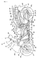
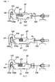
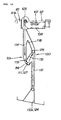
- FIG. 1 is a left side elevational view of a motorcycle according to the present invention.
- the motorcycle 10 includes: main frames 12L, 12R (only reference character 12L on this side is shown) extending obliquely rearwardly downwards from an upper portion of a head pipe 11; down frames 13L, 13R (only reference character 13L on this side is shown) extending obliquely rearwardly downwards from a lower portion of the head pipe 11 and then substantially downwardly and finally rearwardly and connected to the main frames 12L, 12R; seat rails 14L, 14R (only reference character 14L on this side is shown) extending obliquely rearwardly upwards from rear portions of the main frames 12L, 12R; middle frames 17L, 17R (only reference character 17L on this side is shown) interconnecting intermediate points 16L, 16R (only reference character 16L on this side is shown) of the seat rails 14L, 14R and rear end portions of the main frames 12L, 12R; rail stays 18L, 18R (only reference character
- a fuel tank 43 is disposed in a region surrounded by the main frames 12L, 12R and the down frames 13L, 13R, and a first cross member 44 extends between the left and right main frames 12L, 12R above the fuel tank 43.
- a second cross member 45 extends between the left and right down frames 13L, 13R below the fuel tank 43, and a third cross member 46 extends between the left and right seat rails 14L, 14R in the proximity of the pivot plates 21 L, 21 R.
- a rear cross member 47 extends between rear end portions of the left and right seat rails 14L, 14R.
- a radiator unit 51 for cooling the engine 42 is disposed forwardly of the down frames 13L, 13R rearwardly of the front wheel 38, and a coolant reservoir tank 52 is disposed in the proximity of the radiator unit 51.
- a fuel pump 53 a strainer 54 provided below the fuel pump 53 for separating foreign articles such as water or garbage in fuel accommodated in the fuel tank 43 and a flow sensor 55 for detecting the remaining amount of the fuel accommodated in the fuel tank 43 are provided in the inside of the fuel tank 43.
- reference numeral 56 denotes a front disk brake unit; 57 a front disk plate; 58 a front cowl which covers the front of the vehicle; 59 an inner cover which covers a front portion of the vehicle including the head pipe 11 and provided continuously to the front cowl 58; 60 a container equipped on the vehicle; 61 a main cowl for covering side portions of the vehicle; 62 a front fender; 63 a rear fender; 64 an exhaust pipe extending from the power unit 24; 65 a silencer connecting to a rear end portion of the exhaust pipe 64; 66 a side stand; 67 a main stand; and 68 a secondary air reed valve disposed sidewardly of the engine and connected to the exhaust pipe 64 and an intake pipe 77 hereinafter described.
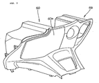
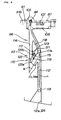
- FIG. 2 is a perspective view of an inner cover which includes the container according to the present invention.
- the inner cover 59 is a member which is attached so as to extend forwardly from rearwardly of the front cowl (reference character 58 of FIG. 1 ) and is provided continuously to the front cowl 58.
- the inner cover 59 is opposed to a front portion of the front seat (reference numeral 33 of FIG. 1 ) on which the driver is to be seated, and is disposed at a position at which the hand of the driver reaches when the user in a seated state reaches out its hand.
- the container 60 is provided on the inner cover 59, and the front face of the container 60 is covered with a lid 60a. Accordingly, the driver can reach out its hand and operate to open and close the container 60 readily.
- the structure of the container 60 is described in detail below with reference to the succeeding figures.
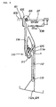
- FIG. 3 is a perspective view illustrating a state wherein the container according to the present invention is positioned at its fully open position, and the container 60 attached to the inner cover 59 is shown in a pulled out state.
- the container 60 includes an accommodation case 81 attached to the inner cover (reference numeral 59 in FIG. 2 ), and a drawer 82 provided for horizontal sliding movement in the accommodation case 81.
- the drawer 82 In the fully open state, the drawer 82 is prevented from coming off the accommodation case 81 by means of a stopper not shown, and if the stopper is rendered inoperative, then the drawer 82 can be removed readily from the accommodation case 81.
- the container 60 includes a drawer 82 for accommodating a small article and an accommodation case 81 for accommodating the drawer 82 for horizontal sliding movement in directions indicated by an arrow mark s.
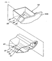
- FIG. 4 is an exploded perspective view showing components of the container according to the present invention.
- the container 60 includes a drawer 82 and an accommodation case 81.
- An intermediately open stopping mechanism 83 for stopping the drawer 82 once at an intermediate position when the drawer 82 is pulled out toward the passenger side is provided on one and the other of the drawer 82 and the accommodation case 81.
- the intermediately open stopping mechanism 83 includes an arm member 85 provided on the drawer 82 and having a pin-like projection 84, and a groove group 86 including a plurality of grooves provided on a bottom plate 81 b of the accommodation case 81 for guiding the pin-like projection 84.
- the groove group 86 is provided on the accommodation case 81. In other words, since the groove group 86 is provided not on the drawer 82 side, the accommodation capacity of the drawer 82 does not decrease, and a sufficient accommodation capacity of the drawer 82 can be assured.
- the arm member 85 is provided on the drawer 82 side, maintenance of the arm member 85 can be performed readily by taking out the drawer 82.
- the groove group 86 is provided on the accommodation case 81 and the arm member 85 is provided on the drawer 82
- the groove group 86 may be provided on the drawer 82 and the arm member 85 may be provided on the accommodation case 81.
- FIG. 5 is a sectional view showing a resilient mechanism for biasing the drawer in the opening direction according to the present invention.
- the resilient mechanism 93 is attached to a small pocket 92 formed by partly expanding a portion of the accommodation case 81 in the proximity of an opening 91 which is an entrance of the accommodation case 81.
- the resilient mechanism 93 includes a shaft portion 94 disposed on the small pocket 92 and attached to the accommodation case 81 side, a drum 95 attached for rotation on the shaft portion 94, a spiral spring 96 in the form of a thin plate wrapped around the drum 95, and a hook member 97 attached to an end portion 96a of the spiral spring 96.
- the resilient mechanism 93 is configured such that the spiral spring 96 is wrapped around the drum 95 and, when this spiral spring 96 is extended, force F for taking up the hook member 97 in a direction toward the drum 95 acts upon the hook member 97.
- the hook member 97 is anchored at a hook anchoring portion 98 formed at an innermost portion of a bottom plate 82b of the drawer 82.
- the hook anchoring portion 98 is disposed such that it assumes a position most proximate to the resilient mechanism 93 when the drawer 82 is at its fully open position (K), but assumes another position spaced most away from the resilient mechanism 93 when the drawer 82 is at its fully closed position (H).
- the drawer 82 By anchoring the hook member 97 of the resilient mechanism 93 at the hook anchoring portion 98 of the drawer 82, the drawer 82 can be biased in a direction toward the fully open position (K).
- the resilient mechanism 93 for resiliently biasing the drawer 82 at the fully closed position (H) toward the opening side is provided on the accommodation case 81, since the drawer 82 tends to move to the fully open position (K), a mechanism for holding the drawer 82 at the fully closed position (H) or an intermediately open position (TK) is required.
- a locking mechanism for holding the drawer 82 at the fully closed position (H) and an intermediately open stopping mechanism for holding the drawer 82 at the intermediately open position (TK) are provided. Details of them are described below.
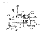
- FIG. 6 is a sectional view showing the arm member having the pin-like projection at the tip end thereof according to the present invention.
- a recessed portion 101 is provided at a rear end portion 99 of the bottom plate 82b of the drawer 82, and the arm member 85 having the pin-like projection 84 at the tip end thereof is provided in the recessed portion 101.
- the arm member 85 includes a support pin 102 attached at the right angle to a horizontal face 101 s of the recessed portion 101, and an arm member 85 attached for pivotal motion in directions perpendicular to the plane of FIG. 6 around the support pin 102 and having a rear end 85b fitted on the support pin 102.
- the arm member 85 has the pin-like projection 84 provided at a tip end 85a thereof and projecting downwardly.
- An end portion 84a of the pin-like projection 84 extends downwardly farther than the bottom face 82c of the bottom plate 82b of the drawer 82 and has a margin for overlapping of a length L with the groove group 86.
- the support pin 102 and the arm member 85 are disposed such that they are accommodated in the recessed portion 101 above the bottom face 82c of the bottom plate 82b.
- the arm member 85 is provided for horizontal pivotal motion as viewed in plan on the drawer 82 and the pin-like projection 84 is provided at the tip end 85a of the arm member 85.
- reference numeral 103 denotes a washer, and 104 a fixing ring for fixing the support pin 102. It is to be noted that the pin-like projection 84 is secured to the arm member 85 by welding.
- FIG. 7 is a view showing the locking mechanism for the arm member having the pin-like project at the tip end thereof according to the present invention and illustrating operation of the locking mechanism.
- the locking mechanism 87 is provided on the accommodation case (reference numeral 81 in FIG. 5 ).
- the locking mechanism 87 includes: as principal components thereof, a holder member 106 attached to the accommodation case 81 side and having a receiving portion 105 of a substantially U shape as viewed in plan for receiving the pin-like projection 84; a stopper 108 provided for sliding movement on the holder member 106 with a spring 107 interposed therebetween for holding or releasing the pin-like projection 84; and a cable 109 connected to the stopper 108 for pulling the stopper 108 in a direction indicated by an arrow mark a.
- the cable 109 is connected to an actuator not shown.
- the spring 107 is a member for biasing the stopper 108 in a direction indicated by an arrow mark b in the figure.
- the cable 109 is pulled to move the stopper 108 in a direction indicated by an arrow mark a against the bias of the spring 107. Consequently, the tip end portion 108a of the stopper 108 does not close up the entrance 105a of the receiving portion 105, and the pin-like projection 84 can be released.
- the pin-like projection 84 is permitted to move in the direction indicated by an arrow mark c and can release the drawer 82 from the fully closed position.
- FIG. 8 is a view showing a configuration of the intermediately open stopping mechanism including the groove group according to the present invention and illustrating operation of the intermediately open stopping mechanism (when the drawer is moved from the fully open position to the fully closed position).
- the pin-like projection 84 When the drawer (reference numeral 82 in FIG. 5 ) is at the fully closed position, the pin-like projection 84 is positioned at a blind alley portion 111, but when the drawer 82 is at the fully open position, the pin-like projection 84 is positioned at an open end portion 113 of a first guide groove 112.
- the intermediately open stopping mechanism 83 includes a groove group 86, which extends in the sliding direction of the drawer 82, on the bottom plate 81 b of the accommodation case 81.
- the groove group 86 guides the pin-like projection 84 provided on the drawer 82.
- the groove group 86 provided on the accommodation case 81 includes: a first guide groove 112 for guiding the pin-like projection 84 when the drawer 82 is closed from the fully open position to the fully closed position; a second guide groove 114 operable to guide the pin-like projection 84 provided on the arm member (reference numeral 85 in FIG. 6 ) when the drawer 82 is opened from the fully closed position to the intermediately open position and having a blind alley portion 111 with which the pin-like projection 84 abuts at the intermediately open position; and a communicating groove 115 for interconnecting the second guide groove and the first guide groove 112 to guide the pin-like projection 84.
- the communicating groove 115 is connected to the blind alley portion 111 so as to make an acute angle (0 ⁇ ⁇ ⁇ 90°) in a direction in which the drawer 82 slidably moves and has, at an entrance 111a of the blind alley portion 111, a non-return mechanism 116 which permits, when the drawer 82 moves from the fully closed position to the intermediately open position, the pin-like projection 84 to pass therethrough to the blind alley portion 111 but constrains, when the drawer 82 moves from the intermediately open position to the fully open position, the pin-like projection 84 to pass therethrough to the communicating groove 115.
- the non-return mechanism 116 is described in detail.
- the blind alley portion 111 is formed in a V shape as viewed in plan, and a portion surrounded by the first guide groove 112, second guide groove 114 and communicating groove 115 is formed as a triangular portion 118.
- a shaft member 121 is provided uprightly in the proximity of a vertex 119 of the triangular portion 118 which faces the blind alley portion 111, and a non-return arm 122 is fitted at a rear end 122b thereof for pivotal motion around the shaft member 121. Further, the non-return arm 122 is attached at a front end 122a thereof for swinging movement around the shaft member 121.
- a spring 123 is interposed between the non-return arm 122 and a retaining member 117 provided uprightly at the triangular portion 118 such that the non-return arm 122 is normally disposed so as to cross the second guide groove 114, but when the pin-like projection 84 passes through the second guide groove 114, the non-return arm 122 is biased by the pin-like projection 84 to open the second guide groove 114.
- the groove group 86 include: a first guide groove 112 for guiding the pin-like projection 84 from the fully open position to the fully closed position of the drawer (reference numeral 82 in FIG. 5 ); a second guide groove 114 extending substantially linearly from the start point at the fully closed position separately from the first guide groove 112 for guiding the pin-like projection 84 from the fully closed position to the intermediate position of the drawer 82; a blind alley portion 111 provided at an end portion of the second guide groove 114 for stopping the pin-like projection 84 at the intermediately open once; and a communicating groove 115 extending in an inclined relationship from the blind alley portion 111 toward the fully closed position side and intersecting with a mid portion of the first guide groove 112.
- a non-return mechanism 116 which permits the pin-like projection 84, which advances from the fully closed position to the intermediately open position along the second guide groove 114, to pass therethrough but prevents the pin-like projection 84 to return to the fully closed position therethrough is provided at the entrance of the blind alley portion 111.
- an open end 124 which extends to and is open at an end portion 81 a of the accommodation case 81, and the open end 124 is formed in a shape of a spread fan.
- the arm member 85 having the pin-like projection 84 can be fitted readily into the first guide groove 112. Accordingly, the drawer 82 can be assembled to the accommodation case 81 readily.
- FIG. 9 is a view showing a configuration and operation of the intermediately open stopping mechanism according to the present invention (when the drawer is placed at the intermediately open position and then moved from the intermediate position to the fully open position).
- the non-return mechanism 116 which permits passage of the pin-like projection 84 which moves from the fully closed position to the intermediately open position along the second guide groove 114 but blocks the pin-like projection 84 from returning to the fully closed position is provided at the entrance 111 a of the blind alley portion 111, after the pin-like projection 84 reaches the blind alley portion 111, the pin-like projection 84 does not return into the second guide groove 114.
- the drawer (reference numeral 82 in FIG. 5 ) can be held at the intermediately open position.
- the pin-like projection 84 stopped at the blind alley portion 111 advances, when the drawer 82 is returned a little, in the direction indicated by an arrow mark n along the communicating groove 115 and comes to a switchover point 126 which is the connection point between the communicating groove 115 and the first guide groove 112. Thereafter, the pin-like projection 84 enters the first guide groove 112. Then, when the drawer 82 is pulled finally, the pin-like projection 84 advances along the first guide groove 112, and the drawer 82 can be pulled out to the fully open position. In short, the driver can move the drawer 82 from the half open position to the fully open position only by pushing and pulling the drawer 82.
- the driver can perform operation for opening the drawer 82, which is at the intermediately open position, to the fully open position very readily. Since the drawer 82 can be opened from the intermediately open position to the fully open position only by pushing and pulling operation, the drawer opening operation does not become cumbersome depending upon the physical features of the driver.
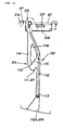
- FIG. 10 is a perspective view illustrating that the drawer is at the intermediately open position or the fully open position.
- the driver can move the drawer 82 to the fully open position only by gripping the lid 60a to push and pull the drawer 82. Accordingly, the driver can perform operation for opening the drawer 82 at the intermediately open position to the fully open position very easily. Further, since the intermediately open stopping mechanism 83 has a simple configuration including the groove group 86 and the arm member 85 which has the pin-like projection 84, assembly of the drawer 82 to the accommodation case 81 can be performed very easily. Further, since the intermediately open stopping mechanism 83 has the simple configuration, also maintenance of the arm member 85 is easy.
- FIG. 11 is a view of an embodiment different from that of FIG. 8 , and the major difference resides in elimination of the non-return mechanism 116.
- the blind alley portion 111 is formed in a V shape as viewed in plan, and a portion surrounded by the first guide groove 112, second guide groove 114 and communicating groove 115 is formed as the triangular portion 118. Further, the blind alley portion 111 is defined such that the V-shape bottom 127 of the blind alley portion 111 is positioned rather near to the first guide groove 112 with respect to the vertex 119 of the triangular portion 118 which faces the blind alley portion 111.
- FIG. 12 is a view of an embodiment different from that of FIG. 9 .
- a resilient mechanism (reference numeral 93 in FIG. 5 ) for resiliently biasing the drawer (reference numeral 82 in FIG. 5 ) at the fully closed position toward the opening side to the fully open position and a stopping cancel mechanism 130 which includes a communicating groove 115 for canceling the stopping by the intermediately open stopping mechanism 83 if the drawer 82 stopped at the intermediately open position is operated in the closing direction by the intermediately open stopping mechanism 83 are provided on the accommodation case (reference numeral 81 in FIG. 5 ). The drawer 82 is stopped at the fully open position after it is operated in the closing direction and the stopping by the intermediately open stopping mechanism 83 is canceled.
- the resilient mechanism (reference numeral 93 in FIG. 5 ) for resiliently biasing the drawer 82 to the opening side is provided on the drawer 82, the pin-like projection 84 abuts with the blind alley portion 111 at the intermediately open position and is biased toward the blind alley portion 111.
- the blind alley portion 111 is formed in a V shape as viewed in plan, and a portion surrounded by the first guide groove 112, second guide groove 114 and communicating groove 115 is formed as the triangular portion 118. Further, the blind alley portion 111 is defined such that the V-shape bottom 127 of the blind alley portion 111 is positioned rather near to the first guide groove 112 with respect to the vertex 119 of the triangular portion 118 which faces the blind alley portion 111. Therefore, the pin-like projection 84 entering the blind alley portion 111 moves into the communicating groove 115 when the drawer 82 is returned a little and comes to the switchover point 126 connecting to the first guide groove 112.
- the resilient mechanism 93 for resiliently biasing the drawer 82 toward the opening side is provided on the drawer 82 and the blind alley portion 111 is defined such that the V-shape bottom 127 of the blind alley portion 111 is positioned rather near to the first guide groove 112, when the drawer 82 is moved from the intermediately open position to the fully open position, the pin-like projection 84 moves into the communicating groove 115 and can finally enter the first guide groove 112. Accordingly, the drawer 82 can be opened to the fully open position.
- the blind alley portion 111 is defined such that the V-shape bottom 127 of the blind alley portion 111 is positioned rather near to the first guide groove 112, the non-return mechanism 116 provided at the entrance 111 a of the blind alley portion 111 is not required any more. Since the requirement for the non-return mechanism 116 is eliminated, the structure of the intermediately open stopping mechanism 83 can be simplified.
- the non-return mechanism to be provided at the entrance of the blind alley portion may be omitted.
- the resilient mechanism for resiliently biasing the drawer to the opening side may be omitted on the accommodation case.
- end portion of the second guide groove or the open end provided at the end portion of the first guide groove may be formed as an open end having an equal groove width without being formed in a shape of a spread fan.
- the present invention can be applied suitably to an accommodation box of a motorcycle.
- the invention is directed to a container wherein operation of moving a drawer having a function of holding the drawer at an intermediately open position from the intermediately open position to the fully open position can be performed readily.
- a container 60 includes a drawer 82 for accommodating a small article, an accommodation case 81 for accommodating the drawer 82 for horizontal sliding movement, and an intermediately open stopping mechanism 83 for stopping the drawer 82 at an intermediate position once when the drawer 82 is pulled out toward the passenger side.
- the intermediately open stopping mechanism 83 includes an arm member 85 provided on the drawer 82 and having a pin-like projection 84 at a tip end thereof, and a groove group 86 provided and extending on the accommodation case 81 for guiding the pin-like projection 84.
- the groove group 86 includes a plurality of guide grooves including a blind alley portion 111 for stopping the pin-like projection 84 at the intermediately open position once.
Landscapes
- Engineering & Computer Science (AREA)
- Mechanical Engineering (AREA)
- Passenger Equipment (AREA)
- Closures For Containers (AREA)
Claims (5)
- Contenant (60) installé sur un véhicule, ayant un tiroir (82) pour loger un petit article, un boîtier de logement (81) pour loger ledit tiroir (82) pour un mouvement coulissant, un mécanisme d'arrêt d'ouverture intermédiaire (83) pour arrêter ledit tiroir (82) une fois qu'il est à une position intermédiaire lorsque ledit tiroir (82) est tiré vers le côté passager, et un mécanisme d'annulation d'arrêt (130) prévu sur ledit boîtier de logement (81) pour annuler l'arrêt par ledit mécanisme d'arrêt d'ouverture intermédiaire (83) lorsque ledit tiroir (82) arrêté à la position intermédiaire par ledit mécanisme d'arrêt d'ouverture intermédiaire (83) est actionné dans la direction de fermeture ; dans lequel
ledit tiroir (82) s'arrête à la position totalement ouverte après l'actionnement dudit tiroir (82) dans la direction de fermeture et l'annulation de l'arrêt par ledit mécanisme d'arrêt d'ouverture intermédiaire (83) ;
ledit mécanisme d'arrêt d'ouverture intermédiaire (83) comprend un élément formant bras (85) prévu sur ledit tiroir (82) ou ledit boîtier de logement (81) pour un mouvement de pivotement à l'horizontal et ayant une saillie en forme de broche (84) à son extrémité terminale, et un groupe de rainures (86) s'étendant dans la direction de coulissement dudit tiroir (82) sur ledit boîtier de logement (81) ou ledit tiroir (82) pour guider ladite saillie en forme de broche (84) ;
ledit groupe de rainures (86) comprend une première rainure de guidage (112) pour guider ladite saillie en forme de broche (84) à partir de la position d'ouverture totale jusqu'à la position totalement fermée dudit tiroir (82), une seconde rainure de guidage (114) s'étendant essentiellement linéairement à partir d'un point de départ de celle-ci à la position totalement fermée séparément de ladite première rainure de guidage (112) pour guider ladite saillie en forme de broche (84) à partir de la position totalement fermée jusqu'à la position intermédiaire dudit tiroir (82), une partie sans issue (111) prévue à une partie terminale de ladite seconde rainure de guidage (114a) pour arrêter ladite saillie en forme de broche (84) une fois dans la position intermédiaire, et une rainure de communication (115) s'étendant à partir de ladite partie sans issue (111) jusqu'à une partie médiane de ladite première rainure de guidage (112) ; et
lorsque ledit tiroir (82) est ouvert, à mesure que ladite saillie en forme de broche (84) avance le long de ladite seconde rainure de guidage (114) s'étendant linéairement, ladite saillie en forme de broche (84) est arrêtée une fois qu'elle se trouve à ladite partie sans issue (111) puis, à mesure que ledit tiroir (82) est repoussé un peu, ladite saillie en forme de broche (84) avance le long dudit chemin de communication, après quoi, à mesure que ledit premier tiroir (82) est tiré vers l'extérieur, ladite saillie en forme de broche (84) avance le long de ladite première rainure de guidage (112) et vient à la position totalement ouverte, mais lorsque ledit tiroir (82) est fermé, à mesure que ladite saillie en forme de broche (84) avance le long de ladite première rainure de guidage (112), ladite saillie en forme de broche (84) se déplace à partir de la position totalement ouverte jusqu'à la position totalement fermée,
caractérisé en ce que :un mécanisme élastique (93) est prévu sur ledit boîtier de logement (81) pour escamoter de manière élastique ledit tiroir (82) à la position totalement fermée vers le côté d'ouverture jusqu'à ce que la position totalement ouverte soit atteinte ;la rainure de communication (115) s'étend dans une relation inclinée à partir de ladite partie sans issue (111) jusqu'au côté position totalement fermée et coupe la partie médiane de ladite première rainure de guidage (112) ; etlorsque ladite saillie en forme de broche (84) est arrêtée à ladite partie sans issue (111) et ledit tiroir (82) est refermé un peu, ladite saillie en forme de broche (84) avance le long dudit chemin de communication et entre dans ladite première rainure de guidage (112). - Contenant (60) installé sur un véhicule selon la revendication 1, caractérisé en ce qu'un mécanisme anti-retour (116) pour permettre le passage de ladite saillie en forme de broche (84) à partir de la position totalement fermée jusqu'à la position d'ouverture intermédiaire le long de la seconde rainure de guidage (114) mais empêcher ladite saillie en forme de broche (84) de revenir à la position totalement fermée est prévu à une entrée de ladite partie sans issue (111a).
- Contenant (60) installé sur un véhicule selon la revendication 1 ou 2, caractérisé en ce que ladite partie sans issue (111) est en forme de V en vue de plan, et une partie entourée par lesdites première rainure de guidage (112), seconde rainure de guidage (114) et rainure de communication (115) est formée sous la forme d'une partie triangulaire (118), et ladite partie sans issue (111) est définie de sorte que le bas de la forme en V de ladite partie sans issue (111) est placé assez près de ladite première rainure de guidage (112) par rapport au sommet (119) de ladite partie triangulaire (118) qui fait face à ladite partie sans issue (111).
- Contenant (60) installé sur un véhicule selon l'une quelconque des revendications 1 à 3, caractérisé en ce que ledit groupe de rainures (86) est prévu sur ledit boîtier de logement (81) alors que ledit élément formant bras (85) est prévu sur ledit tiroir (82).
- Contenant (60) installé sur un véhicule selon l'une quelconque des revendications 1 à 4, caractérisé en ce qu'une partie terminale de ladite seconde rainure de guidage (114a) ou une partie terminale de ladite première rainure de guidage a une extrémité ouverte qui s'étend vers et est ouverte à une partie terminale dudit boîtier de logement (81a), et ladite extrémité ouverte (124) est formée en une forme d'éventail ouvert.
Applications Claiming Priority (1)
| Application Number | Priority Date | Filing Date | Title |
|---|---|---|---|
| JP2006351738A JP4801581B2 (ja) | 2006-12-27 | 2006-12-27 | 車両に装備される物入れ |
Publications (2)
| Publication Number | Publication Date |
|---|---|
| EP1939081A1 EP1939081A1 (fr) | 2008-07-02 |
| EP1939081B1 true EP1939081B1 (fr) | 2009-11-25 |
Family
ID=38979653
Family Applications (1)
| Application Number | Title | Priority Date | Filing Date |
|---|---|---|---|
| EP07021326A Expired - Fee Related EP1939081B1 (fr) | 2006-12-27 | 2007-10-31 | Conteneur équipé sur véhicule |
Country Status (6)
| Country | Link |
|---|---|
| US (1) | US7854486B2 (fr) |
| EP (1) | EP1939081B1 (fr) |
| JP (1) | JP4801581B2 (fr) |
| CN (1) | CN101209727B (fr) |
| DE (1) | DE602007003431D1 (fr) |
| ES (1) | ES2335703T3 (fr) |
Families Citing this family (5)
| Publication number | Priority date | Publication date | Assignee | Title |
|---|---|---|---|---|
| CN201182372Y (zh) * | 2008-03-13 | 2009-01-21 | 佛山市顺德区泰明金属制品厂有限公司 | 抽屉滑轨闭合装置 |
| JP2011201515A (ja) * | 2010-03-26 | 2011-10-13 | Honda Motor Co Ltd | サドルバックおよび該バッグを備えた自動二輪車 |
| TWI507114B (zh) * | 2013-09-30 | 2015-11-01 | Hon Hai Prec Ind Co Ltd | 可抽取式裝載裝置 |
| US10023255B1 (en) * | 2015-10-26 | 2018-07-17 | Truman R Davis | Transportation storage system and method of use |
| CN114847683A (zh) * | 2022-04-18 | 2022-08-05 | 拉扎斯网络科技(上海)有限公司 | 一种储物装置 |
Family Cites Families (15)
| Publication number | Priority date | Publication date | Assignee | Title |
|---|---|---|---|---|
| US2695831A (en) * | 1951-12-04 | 1954-11-30 | Sigal Solomon | Table with drawer and guide |
| US3539239A (en) * | 1968-10-23 | 1970-11-10 | Rubbermaid Inc | Cabinet with retractable door |
| DE3300926C2 (de) * | 1983-01-13 | 1986-11-13 | Audi AG, 8070 Ingolstadt | Ablagebehälter, insbesondere für Kraftfahrzeuge |
| US4494806A (en) * | 1983-05-13 | 1985-01-22 | Leslie Metal Arts Company | Spring loaded drawer assembly with mechanical damping |
| US4712845A (en) * | 1986-01-27 | 1987-12-15 | Ni Industries, Inc. | Self-opening receptacle assembly with adjustable rollers |
| JPH01159281A (ja) | 1987-12-16 | 1989-06-22 | Tokyo Electric Co Ltd | 印字ギヤツプ調整装置 |
| JP2611488B2 (ja) * | 1990-04-25 | 1997-05-21 | 日産自動車株式会社 | 電動式格納スイッチ装置 |
| JP2539974Y2 (ja) * | 1990-06-18 | 1997-07-02 | 株式会社ニフコ | 物品収納装置 |
| DE4038324A1 (de) * | 1990-11-30 | 1992-06-04 | Happich Gmbh Gebr | Behaeltnis, wie ascher, ablagefach o. dgl. insbesondere fuer fahrzeuge |
| US5393137A (en) * | 1993-06-11 | 1995-02-28 | Illinois Tool Works Inc. | Damper assembly |
| DE19636528A1 (de) | 1996-09-09 | 1998-03-19 | Fischer Artur Werke Gmbh | Fahrzeugascher |
| JPH1159281A (ja) | 1997-08-12 | 1999-03-02 | Kojima Press Co Ltd | 多段開閉制御機構及びそれを用いた車両用引出し物 |
| JP3871931B2 (ja) * | 2001-12-27 | 2007-01-24 | 本田技研工業株式会社 | 小型車両用物品収納構造 |
| JP4020755B2 (ja) * | 2002-10-31 | 2007-12-12 | 株式会社ニフコ | 自動車の小物入れ兼用カップホルダ装置 |
| JP4372565B2 (ja) * | 2004-01-20 | 2009-11-25 | 本田技研工業株式会社 | 車両の収納構造 |
-
2006
- 2006-12-27 JP JP2006351738A patent/JP4801581B2/ja not_active Expired - Fee Related
-
2007
- 2007-10-30 US US11/978,727 patent/US7854486B2/en not_active Expired - Fee Related
- 2007-10-31 ES ES07021326T patent/ES2335703T3/es active Active
- 2007-10-31 EP EP07021326A patent/EP1939081B1/fr not_active Expired - Fee Related
- 2007-10-31 DE DE602007003431T patent/DE602007003431D1/de active Active
- 2007-12-20 CN CN2007101597147A patent/CN101209727B/zh active Active
Also Published As
| Publication number | Publication date |
|---|---|
| US20080157554A1 (en) | 2008-07-03 |
| DE602007003431D1 (de) | 2010-01-07 |
| EP1939081A1 (fr) | 2008-07-02 |
| CN101209727A (zh) | 2008-07-02 |
| ES2335703T3 (es) | 2010-03-31 |
| JP4801581B2 (ja) | 2011-10-26 |
| CN101209727B (zh) | 2010-12-01 |
| US7854486B2 (en) | 2010-12-21 |
| JP2008162321A (ja) | 2008-07-17 |
Similar Documents
| Publication | Publication Date | Title |
|---|---|---|
| EP1939081B1 (fr) | Conteneur équipé sur véhicule | |
| JP5342515B2 (ja) | 充電口構造および鞍乗り型車両 | |
| US7841639B2 (en) | Utility vehicle equipped with extendable cargo bed | |
| US6709042B2 (en) | Motorcycle with window screen structure | |
| US7448663B2 (en) | Guard structure for vehicle seat lock | |
| EP1939078B1 (fr) | Motocyclette | |
| JP4451140B2 (ja) | 車両におけるロック解除操作部材配設構造 | |
| JP4991349B2 (ja) | スクータ型車両 | |
| JP2007099098A (ja) | 自動二輪車 | |
| US8002305B2 (en) | Low-floor type vehicle | |
| EP3190034A1 (fr) | Dispositif de pare-brise d'un véhicule de type à selle | |
| JP3610760B2 (ja) | スクータ型車両のフューエルリッド装置 | |
| US20080197647A1 (en) | Front portion structure of vehicle | |
| JP2009227155A (ja) | 小型車両用シート構造 | |
| JP4928976B2 (ja) | 車両のキーシリンダ配設構造 | |
| JP4372565B2 (ja) | 車両の収納構造 | |
| JP4224977B2 (ja) | 自動二輪車の車体構造 | |
| JP4372564B2 (ja) | 車両におけるロック解除操作子配設構造 | |
| JP2724748B2 (ja) | 自動二輪車 | |
| JPS6234870A (ja) | スク−タ型車輛の物入れ装置 | |
| JP6563993B2 (ja) | 鞍乗型車両 | |
| JP4581944B2 (ja) | 自動二輪車のサイドバッグ支持装置 | |
| EP3929013A1 (fr) | Véhicule à enfourcher | |
| JP2020104821A (ja) | 鞍乗り型車両の収納部構造 | |
| JPH0541987Y2 (fr) |
Legal Events
| Date | Code | Title | Description |
|---|---|---|---|
| PUAI | Public reference made under article 153(3) epc to a published international application that has entered the european phase |
Free format text: ORIGINAL CODE: 0009012 |
|
| 17P | Request for examination filed |
Effective date: 20071031 |
|
| AK | Designated contracting states |
Kind code of ref document: A1 Designated state(s): AT BE BG CH CY CZ DE DK EE ES FI FR GB GR HU IE IS IT LI LT LU LV MC MT NL PL PT RO SE SI SK TR |
|
| AX | Request for extension of the european patent |
Extension state: AL BA HR MK RS |
|
| AKX | Designation fees paid |
Designated state(s): DE ES FR IT |
|
| GRAP | Despatch of communication of intention to grant a patent |
Free format text: ORIGINAL CODE: EPIDOSNIGR1 |
|
| GRAS | Grant fee paid |
Free format text: ORIGINAL CODE: EPIDOSNIGR3 |
|
| GRAA | (expected) grant |
Free format text: ORIGINAL CODE: 0009210 |
|
| RAP1 | Party data changed (applicant data changed or rights of an application transferred) |
Owner name: HONDA MOTOR CO., LTD. |
|
| AK | Designated contracting states |
Kind code of ref document: B1 Designated state(s): DE ES FR IT |
|
| REF | Corresponds to: |
Ref document number: 602007003431 Country of ref document: DE Date of ref document: 20100107 Kind code of ref document: P |
|
| REG | Reference to a national code |
Ref country code: ES Ref legal event code: FG2A Ref document number: 2335703 Country of ref document: ES Kind code of ref document: T3 |
|
| PLBE | No opposition filed within time limit |
Free format text: ORIGINAL CODE: 0009261 |
|
| STAA | Information on the status of an ep patent application or granted ep patent |
Free format text: STATUS: NO OPPOSITION FILED WITHIN TIME LIMIT |
|
| 26N | No opposition filed |
Effective date: 20100826 |
|
| PG25 | Lapsed in a contracting state [announced via postgrant information from national office to epo] |
Ref country code: IT Free format text: LAPSE BECAUSE OF NON-PAYMENT OF DUE FEES Effective date: 20101031 |
|
| REG | Reference to a national code |
Ref country code: FR Ref legal event code: PLFP Year of fee payment: 10 |
|
| REG | Reference to a national code |
Ref country code: DE Ref legal event code: R084 Ref document number: 602007003431 Country of ref document: DE |
|
| PGFP | Annual fee paid to national office [announced via postgrant information from national office to epo] |
Ref country code: FR Payment date: 20160919 Year of fee payment: 10 |
|
| PGFP | Annual fee paid to national office [announced via postgrant information from national office to epo] |
Ref country code: ES Payment date: 20160915 Year of fee payment: 10 |
|
| REG | Reference to a national code |
Ref country code: FR Ref legal event code: ST Effective date: 20180629 |
|
| PG25 | Lapsed in a contracting state [announced via postgrant information from national office to epo] |
Ref country code: FR Free format text: LAPSE BECAUSE OF NON-PAYMENT OF DUE FEES Effective date: 20171031 |
|
| REG | Reference to a national code |
Ref country code: ES Ref legal event code: FD2A Effective date: 20181226 |
|
| PGFP | Annual fee paid to national office [announced via postgrant information from national office to epo] |
Ref country code: DE Payment date: 20181016 Year of fee payment: 12 |
|
| PG25 | Lapsed in a contracting state [announced via postgrant information from national office to epo] |
Ref country code: ES Free format text: LAPSE BECAUSE OF NON-PAYMENT OF DUE FEES Effective date: 20171101 |
|
| REG | Reference to a national code |
Ref country code: DE Ref legal event code: R119 Ref document number: 602007003431 Country of ref document: DE |
|
| PG25 | Lapsed in a contracting state [announced via postgrant information from national office to epo] |
Ref country code: DE Free format text: LAPSE BECAUSE OF NON-PAYMENT OF DUE FEES Effective date: 20200501 |
|
| PGFP | Annual fee paid to national office [announced via postgrant information from national office to epo] |
Ref country code: IT Payment date: 20200911 Year of fee payment: 14 |
|
| PG25 | Lapsed in a contracting state [announced via postgrant information from national office to epo] |
Ref country code: IT Free format text: LAPSE BECAUSE OF NON-PAYMENT OF DUE FEES Effective date: 20211031 |