EP1938154B1 - Selbsttätig verfahrbares bodenstaub-aufsammelgerät - Google Patents
Selbsttätig verfahrbares bodenstaub-aufsammelgerät Download PDFInfo
- Publication number
- EP1938154B1 EP1938154B1 EP06806800.6A EP06806800A EP1938154B1 EP 1938154 B1 EP1938154 B1 EP 1938154B1 EP 06806800 A EP06806800 A EP 06806800A EP 1938154 B1 EP1938154 B1 EP 1938154B1
- Authority
- EP
- European Patent Office
- Prior art keywords
- movement
- passive wheel
- floor
- collector
- dust collector
- Prior art date
- Legal status (The legal status is an assumption and is not a legal conclusion. Google has not performed a legal analysis and makes no representation as to the accuracy of the status listed.)
- Not-in-force
Links
- 239000000428 dust Substances 0.000 title claims description 19
- 230000033001 locomotion Effects 0.000 claims description 18
- 239000011435 rock Substances 0.000 claims 1
- 238000012544 monitoring process Methods 0.000 description 4
- 230000001960 triggered effect Effects 0.000 description 3
- 238000004140 cleaning Methods 0.000 description 2
- 238000012937 correction Methods 0.000 description 2
- 230000000977 initiatory effect Effects 0.000 description 2
- 238000000034 method Methods 0.000 description 2
- 238000010408 sweeping Methods 0.000 description 2
- 229910000831 Steel Inorganic materials 0.000 description 1
- 238000013459 approach Methods 0.000 description 1
- 230000003542 behavioural effect Effects 0.000 description 1
- 230000000903 blocking effect Effects 0.000 description 1
- 238000006243 chemical reaction Methods 0.000 description 1
- 238000013461 design Methods 0.000 description 1
- 238000010586 diagram Methods 0.000 description 1
- 230000000694 effects Effects 0.000 description 1
- 230000005764 inhibitory process Effects 0.000 description 1
- 230000007257 malfunction Effects 0.000 description 1
- 238000004321 preservation Methods 0.000 description 1
- 238000011084 recovery Methods 0.000 description 1
- 230000000630 rising effect Effects 0.000 description 1
- 239000002689 soil Substances 0.000 description 1
- 239000010959 steel Substances 0.000 description 1
- 239000000725 suspension Substances 0.000 description 1
- 230000007704 transition Effects 0.000 description 1
Images

Classifications
-
- G—PHYSICS
- G05—CONTROLLING; REGULATING
- G05D—SYSTEMS FOR CONTROLLING OR REGULATING NON-ELECTRIC VARIABLES
- G05D1/00—Control of position, course, altitude or attitude of land, water, air or space vehicles, e.g. using automatic pilots
- G05D1/02—Control of position or course in two dimensions
- G05D1/021—Control of position or course in two dimensions specially adapted to land vehicles
- G05D1/0268—Control of position or course in two dimensions specially adapted to land vehicles using internal positioning means
- G05D1/0272—Control of position or course in two dimensions specially adapted to land vehicles using internal positioning means comprising means for registering the travel distance, e.g. revolutions of wheels
Definitions
- the invention relates to a self-propelled ground dust collecting device with an electromotive drive, a dust collector and a cover, wherein the collecting device has one or more driven Verfahrer and a non-driven, rotating passive wheel, further correction measures for recovering the free mobility of the Aufsammelatorss triggered are, in the case that a movement inhibition of the Aufsammeloaras is recognized by this.
- Floor dust collectors of the type in question are known. These clean independently and without assistance in usual apartments possibly different and changing floor coverings by sweeping and possibly further by suction. These collection devices adapt to the variable floor height (carpet, hard floor and their transitions). For example, on the DE 102 42 257 A1 directed.
- a collection device of the type in question must not be bogged down by obstacles. Basically, this device may be stuck by unsuitable behavioral strategies or by mechanical jamming, with mechanical jamming in the form of driving on flat obstacles or by driving under, for example. Under cabinets or radiators may occur.
- solutions are known in which a drive is largely prevented by a sprung suspension.
- a self-propelled ground dust collection device that includes a sensor that determines if a wheel is dodging down. This can happen when the unit is riding on a step of a staircase and partially overhangs.
- the invention is concerned with the Aufgbengnagna, a ground dust collecting device in such a way that basically its mobility is maintained.
- the correction measure may be that the ground dust collecting device first stops the journey and then starts a suitable release algorithm or reversing the maneuver that has led to the confinement, performs or rocking, about effetternernierende rotations and movements, performs or lifting the embarksammelatorss when driving or lowering the Aufsammeltechniks at a Underride performs.
- a seizing is prevented by driving on or driving under an obstacle.
- the preservation of mobility is a prerequisite for the complete driving on a surface and the reliable return to the base station, at which a recharging of an accumulator optionally provided in the accumulator and, where appropriate, also the emptying of the Aufsammel advocatess takes place.
- three support points are required. In general, these are two driven Verfahrer and a non-driven, follower Passivrad.
- the rotation of the traversing wheels is continuously monitored by infrared or Hall sensors. If the pick-up device encounters an obstacle, it may be the case that the travel wheels continue to rotate without effecting forward movement of the pick-up device.
- the non-driven, follower passive wheel only turns when the pickup device moves forwards or backwards. If the pick-up device moves under an obstacle and jams there, this can also lead to a blocking of the traveling wheels. The passive wheel will also stand still in this case.
- the rotation of the passive wheel is monitored by a suitable sensor. If the speed of rotation of the passive wheel falls below a limit speed specified by the number and arrangement of the sensors and by an electrical circuit, then it is assumed that the collecting device has become stuck. Exceptions here are the events “Start” and “Turn left or right", in which also no rotation of the passive wheel is to be expected. These exceptional events are detected by a corresponding electronic circuit, so that a standstill of the passive wheel here has no effect on the handling of the Aufsammel convinceds.
- the movement of the passive wheel can be monitored mechanically, optically or magnetically. When monitoring the rotation of the passive wheel, the undershooting of a minimum speed is detected. This can be done by rotating signal generators such as magnets (Hall sensors) or timing discs (when using a light / infrared light beam). For example, magnetic pulses that are picked up by a Hall sensor are conceivable.
- FIG. 1 Shown and described is first with reference to FIG. 1 a self-propelled ground dust collecting device 1 with a chassis 2 and a cover 2 covering the chassis 2.
- the autonomously operating Aufsammel réelle 1 is designed as a sweeping device, including a rotatable about a horizontal axis x brush 4 is provided, which in the illustrated embodiment, the device bottom 5 in the region of a rectangular cutout 6 down, that is, in the direction of the soil to be maintained.
- the drive of the brush 4 via an electric motor, not shown, which is arranged by a, relative to the usual direction of travel r rear region arranged, also not shown accumulator is fed.
- the Aufsammelêt 1 also has two, partly the device bottom 5 passing through Verfahrcken 7, each Verfahrrad 7 is driven by a separate electric motor, which in addition to the usual, straight-line method of the device 1 and a turning or turning the same is possible.
- This Verfahrer 7 are arranged relative to the usual direction of travel r back of the brush 4.
- a non-driven, follower Passivrad 8 is provided, according to which the ground dust collecting device 1 by means of the Verfahrer 7 and the Passivrades 8 has three support points.
- the passive wheel 8 is monitored with respect to its movement.
- This motion monitoring of the passive wheel can be done mechanically, optically or magnetically.
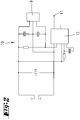
- the evaluated signal is transferred via the interface 11 to another electronics, for the possible initiation of a corrective action.
- another electronics for the possible initiation of a corrective action.
- Also conceivable here is the arrangement of a plurality of magnets, which are distributed uniformly over the circumference of the passive wheel 8.
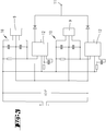
- FIG. 3 also illustrated the arrangement of several Hall sensors 9 conceivable.
- the embodiment according to the invention counteracts a jamming of the collecting device 1.
- the approach to an obstacle or driving under an obstacle is detected early, so that in good time a measure for the recovery or to maintain the free mobility of the recording device can be triggered.
Landscapes
- Engineering & Computer Science (AREA)
- Aviation & Aerospace Engineering (AREA)
- Radar, Positioning & Navigation (AREA)
- Remote Sensing (AREA)
- Physics & Mathematics (AREA)
- General Physics & Mathematics (AREA)
- Automation & Control Theory (AREA)
- Electric Vacuum Cleaner (AREA)
- Control Of Position, Course, Altitude, Or Attitude Of Moving Bodies (AREA)
- Electric Suction Cleaners (AREA)
- Filters For Electric Vacuum Cleaners (AREA)
Description
- Die Erfindung betrifft ein selbsttätig verfahrbares Bodenstaub-Aufsammelgerät mit einem elektromotrischen Antrieb, einem Staubsammelbehälter und einer Abdeckhaube, wobei das Aufsammelgerät ein oder mehrere angetriebene Verfahrräder und ein nicht angetriebenes, mitlaufendes Passivrad aufweist, wobei weiter Korrektur-Maßnahmen zur Rückgewinnung der freien Beweglichkeit des Aufsammelgerätes auslösbar sind, im Falle, dass eine Bewegungshinderung des Aufsammelgerätes von diesem erkannt wird.
- Bodenstaub-Aufsammelgeräte der in Rede stehenden Art sind bekannt. Diese reinigen selbständig und ohne Hilfestellung in üblichen Wohnungen gegebenenfalls unterschiedliche und wechselnde Bodenbeläge durch Kehren und gegebenenfalls weiter durch Saugen. Diese Aufsammelgeräte passen sich der variablen Bodenhöhe (Teppich, Hartboden und deren Übergänge) an. So wird beispielsweise auf die
DE 102 42 257 A1 verwiesen. Um die Mobilität und damit die Arbeitsfähigkeit zu erhalten, darf sich ein Aufsammelgerät der in Rede stehenden Art nicht an Hindernissen festfahren. Grundsätzlich kann sich dieses Gerät durch ungeeignete Verhaltensstrategien oder durch mechanisches Verklemmen festfahren, wobei mechanisches Verklemmen in Form des Auffahrens auf flache Hindernisse oder durch Unterfahren bspw. unter Schränke oder Heizungskörper auftreten kann. Diesbezüglich sind Lösungen bekannt, bei welchen ein Auffahren weitestgehend durch ein gefedertes Fahrwerk verhindert wird. Bei kontinuierlich ansteigenden Hindernissen wie Lampenfüßen oder Stahlrohrstühlen mit umlaufendem Schwingrohr verfahren sich jedoch diese bekannten Aufsammelgeräte fest und schalten ab. Zum Schutz gegen Unterfahren ist es bekannt Ultraschall-Abstandssensoren vorzusehen, welche die Hindernisse bereits aus der Distanz erkennen. Diese Sensorik versagt jedoch bei sehr schmalen Stegen, wie beispielsweise Halterungen von Heizkörpern. Wird ein Hindernis nicht über die Sensorik erkannt, kann sich das Aufsammelgerät unter diesem Hindernis festklemmen. Ein Auffahren bzw. Unterfahren hat zunächst zur Folge, dass der Reinigungsfortgang nicht fortgesetzt werden kann. Das Festfahren wird bei den bekannten Geräten nicht erkannt, so dass vorgesehene Reinigungsbürsten weiter in Betrieb sind, dass heißt, weiter drehen ohne dass sich der Roboter bewegt. Somit sind Bodenschädigungen und gegebenenfalls Schädigungen des Aufsammelgerätes zu erwarten. Aus derWO 2005/083541 A ist ein selbsttätig verfahrbares Bodenstaub-Aufsammelgerät bekannt, das einen Sensor aufweist, der feststellt, ob ein Rad nach unten ausweicht. Dies kann eintreten, wenn das Gerät auf einer Stufe einer Treppe fährt und teilweise überkragt. - Ausgehend von dem zuletzt genannten Stand der Technik beschäftigt sich die Erfindung mit der Aufgbenstellung, ein Bodenstaub-Aufsammelgerät so auszugestalten, dass grundsätzlich seine Mobilität erhalten bleibt.
- Diese Aufgabe ist beim Gegenstand des Anspruches 1 gelöst, wobei darauf abgestellt ist, dass das Passivrad hinsichtlich seiner Bewegung überwacht wird zur möglichen Einleitung einer Korrektur-Maßnahme bei einer Unterschreitung einer vorgegebenen Grenzgeschwindigkeit, wobei die Korrektur-Maßnahme sein kann, dass das Bodenstaub-Aufsammelgerät zunächst die Fahrt stoppt und hiernach einen geeigneten Befreiungsalgorithmus startet oder eine Umkehr des Fahrmanövers, welches zum Festfahren geführt hat, durchführt oder ein Freischaukeln, etwa durchalternierende Drehungen und Fahrbewegungen, durchführt oder ein Anheben des Aufsammelgerätes bei einem Auffahren bzw. ein Absenken des Aufsammelgerätes bei einem Unterfahren durchführt. Zufolge dieser Ausgestaltung wird einem Festfahren durch Auffahren bzw. Unterfahren eines Hindernisses entgegengewirkt. Der Zustand "Festgefahren" wird frühzeitig und zuverlässig erkannt, so dass eine Maßnahme zur Rückgewinnung der freien Beweglichkeit des Aufsammelgerätes auslösbar ist. Eine solche Maßnahme kann sein, wie auch im Anspruch 1 ausgeführt, dass das Bodenstaub-Aufsammelgerät zunächst die Fahrt stoppt und hiernach einen geeigneten Befreiungsalgorithmus startet. Hierdurch bleibt dessen Mobilität erhalten.
- Die Erhaltung der Mobilität ist Voraussetzung für das vollständige Befahren einer Fläche und das zuverlässige Zurückfinden zur Basisstation, an welcher ein Wiederaufladen eines in dem Aufsammelgerät gegebenenfalls vorgesehenen Akkumulators und darüber hinaus gegebenenfalls auch das Entleeren des Aufsammelgerätes erfolgt.
- Weitere mögliche Maßnahmen zur Rückgewinnung der freien Beweglichkeit des Aufsammelgerätes, wie auch im Anspruch 1 enthalten, können in einer Umkehr des Fahrmanövers, welches zum Festfahren geführt hat, bestehen. Weiter alternativ kann auch ein Freischaukeln als Maßnahme greifen, so durch alternierende Drehungen und Fahrbewegungen. Darüber hinaus ist als Maßnahme auch ein Anheben des Aufsammelgerätes bei einem Auffahren bzw. ein Absenken des Aufsammelgerätes bei einem Unterfahren denkbar.
- Zur Gewährleistung einer statisch bestimmten Auflage des Bodenstaub-Aufsammelgerätes auf einer Ebene sind drei Auflagepunkte erforderlich. In der Regel sind dies zwei angetriebene Verfahrräder und ein nicht angetriebenes, mitlaufendes Passivrad. Die Drehung der Verfahrräder wird kontinuierlich durch Infrarot- oder Hallsensoren überwacht. Fährt das Aufsammelgerät auf ein Hindernis auf, so kann der Fall auftreten, dass sich die Verfahrräder weiter drehen ohne eine Vorwärtsbewegung des Aufsammelgerätes zu bewirken. Das nicht angetriebene, mitlaufende Passivrad dreht sich hingegen nur dann, wenn sich das Aufsammelgerät vorwärts oder rückwärts bewegt. Fährt das Aufsammelgerät unter ein Hindernis und klemmt dort fest, so kann dies auch zu einem Blockieren der Verfahrräder führen. Das Passivrad wird auch in diesem Fall still stehen.
- Durch die erfindungsgemäße Ausgestaltung wird durch eine geeignete Sensorik die Drehung des Passivrades überwacht. Unterschreitet die Drehgeschwindigkeit des Passivrades eine durch Anzahl und Anordnung der Sensoren sowie durch eine elektrische Schaltung vorgegebene Grenzgeschwindigkeit, so wird davon ausgegangen, dass sich das Aufsammelgerät festgefahren hat. Ausnahmen bilden hierbei die Ereignisse "Start" und "Drehung links oder rechts", in welchen auch keine Drehung des Passivrades zu erwarten ist. Diese Ausnahmeereignisse werden durch eine entsprechende elektronische Schaltung erfasst, so dass ein Stillstand des Passivrades hierbei keinen Einfluss auf das Fahrverhalten des Aufsammelgerätes hat. Die Bewegung des Passivrades kann mechanisch, optisch oder auch magnetisch überwacht werden.
Bei der Überwachung der Drehung des Passivrades wird die Unterschreitung einer Mindestgeschwindigkeit erkannt. Dies kann durch umlaufende Signalgeber wie Magnete (bei Hallsensoren) oder Taktscheiben (bei Verwendung eines Licht-/Infrarotlichtstrahles) geschehen. Denkbar sind zum Beispiel magnetische Impulse, die von einem Hall-Sensor aufgenommen werden. - Nachstehend ist die Erfindung anhand der beigefügten Zeichnungen, welche lediglich zwei Ausführungsbeispiele darstellen, näher erläutert. Es zeigt:
- Fig. 1
- eine perspektivische Unteransicht des erfindungsgemäßen Aufsammelgerätes;
- Fig. 2
- einen Plan einer elektronischen Schaltung zur Erfassung und Auswertung der Drehgeschwindigkeit des Passivrades in einer ersten Ausführungsform;
- Fig. 3
- eine elektronische Schaltung gemäß
Figur 2 , jedoch eine zweite Ausführungsform betreffend. - Dargestellt und beschrieben ist zunächst mit Bezug zu
Figur 1 ein selbsttätig verfahrbares Bodenstaub-Aufsammelgerät 1 mit einem Chassis 2 und einer das Chassis 2 überdeckenden Abdeckhaube 3. - Das autonom arbeitende Aufsammelgerät 1 ist als Kehrgerät ausgebildet, wozu eine um eine Horizontalachse x drehbare Bürste 4 vorgesehen ist, welche in dem dargestellten Ausführungsbeispiel den Geräteboden 5 im Bereich eines Rechteckausschnittes 6 nach unten, dass heißt in Richtung auf den zu pflegenden Boden durchsetzt. Der Antrieb der Bürste 4 erfolgt über einen nicht dargestellten Elektromotor, welcher von einem, bezogen auf die übliche Verfahrrichtung r rückwärtigen Bereich angeordneten, gleichfalls nicht dargestellten Akkumulator gespeist wird.
- Der mittels der Bürste 4 aufgesammelte Bodenstaub wird in einen rückwärtig angeordneten, nicht näher dargestellten Staubsammelbehälter geworfen.
- Das Aufsammelgerät 1 weist zudem zwei, teilweise den Geräteboden 5 durchsetzende Verfahrräder 7 auf, wobei jedes Verfahrrad 7 über einen gesonderten Elektromotor angetrieben wird, womit neben dem üblichen, geradlinigen Verfahren des Gerätes 1 auch ein Drehen bzw. Wenden desselben ermöglicht ist.
- Diese Verfahrräder 7 sind bezogen auf die übliche Verfahrrichtung r rückwärtig der Bürste 4 angeordnet. Wie weiter aus der Unteransicht in
Figur 1 zu erkennen, ist in üblicher Verfahrrichtung r vor der Bürste 4 ein nicht angetriebenes, mitlaufendes Passivrad 8 vorgesehen, zufolge dessen das Bodenstaub-Aufsammelgerät 1 mittels der Verfahrräder 7 und des Passivrades 8 drei Auflagepunkte aufweist. - Bezüglich der weiteren, hier nicht näher beschriebenen Funktionsteile sowie des Arbeits- und Verfahrverhaltens des Bodenstaub-Aufsammelgerätes 1 wird auf die eingangs erwähnte
DE 102 42 257 A1 verwiesen, deren Inhalt hiermit vollinhaltlich in die Offenbarung vorliegender Erfindung miteinbezogen wird, auch zu dem Zwecke, Merkmale dieser Patentanmeldung in Ansprüche vorliegender Erfindung mit einzubeziehen. - Um eine Bewegungshinderung des Aufsammelgerätes 1, beispielsweise ein Festfahren durch Auf- oder Unterfahren zu erkennen, wird das Passivrad 8 hinsichtlich seiner Bewegung überwacht. Diese Bewegungsüberwachung des Passivrades kann mechanisch, optisch oder auch magnetisch erfolgen.
- Anhand des in
Figur 2 dargestellten elektronischen Schaltplans wird eine Überwachung mittels eines Hall-Sensors 9 beschrieben. Bei der Überwachung der Drehung des mitlaufenden, nicht angetriebenen Passivrades 8 kann die Unterschreitung einer Mindestgeschwindigkeit erkannt werden. Dies wird in dem dargestellten Ausführungsbeispiel durch umlaufende Signalgeber wie Magnete realisiert. Die magnetischen Impulse werden von dem Hall-Sensor 9 aufgenommen und auf den Triggereingang eines re-triggerbaren Monoflops 10 gegeben. Passiert ein in das Passivrad 8 integrierter Magnet den Hall-Sensor 9, schaltet dieser den Monoflop für eine über ein RC-Glied einstellbare Zeitspanne von LOW auf HIGH. Im normalen Fahrbetrieb ist diese Zeit so bemessen, dass der Magnet den Hall-Sensor 9 erneut passiert und somit das Monoflop 10 retriggert, bevor die Zeit abgelaufen ist. Geschieht dies nicht, signalisiert der Rückfall des Monoflops 10 auf LOW die Fehlfunktion. Das ausgewertete Signal wird über die Schnittstelle 11 an eine weitere Elektronik übergeben, zur möglichen Einleitung einer Korrekturmaßnahme. Denkbar ist hier auch die Anordnung mehrerer Magnete, die über den Umfang des Passivrades 8 gleichmäßig verteilt sind. Weiter ist wie inFigur 3 dargestellt auch die Anordnung mehrerer Hall-Sensoren 9 denkbar. - Mögliche Reaktionen des Aufsammelgerätes 1 zur Erhaltung seiner Mobilität können die Umkehr des Fahrmanövers, welches zum Festfahren geführt hat, das Freischaukeln durch alternierende Drehungen und Fahrbewegungen oder ein Anheben bei Auffahren oder Absenken bei Unterfahren des Aufsammelgerätes 1 sein.
- Durch die erfindungsgemäße Ausgestaltung ist einem Festfahren des Aufsammelgerätes 1 entgegengewirkt. Das Auffahren auf ein Hindernis oder das Unterfahren unter ein Hindernis wird frühzeitig erkannt, so dass rechtzeitig eine Maßnahme zur Rückgewinnung bzw. zur Beibehaltung der freien Beweglichkeit des Aufnahmegerätes auslösbar ist.
- Alle offenbarten Merkmale sind (für sich) erfindungswesentlich. In die Offenbarung der Anmeldung wird hiermit auch der Offenbarungsinhalt der zugehörigen/beigefügten Prioritätsunterlagen (Abschrift der Voranmeldung) vollinhaltlich mit einbezogen, auch zu dem Zweck, Merkmale dieser Unterlagen in Ansprüche vorliegender Anmeldung mit aufzunehmen.
Claims (4)
- Selbsttätig verfahrbares Bodenstaub-Aufsammelgerät (1) mit einem elektromotorischen Antrieb, einem Staubsammelbehälter und einer Abdeckhaube (3), wobei das Aufsammelgerät (1) ein oder mehrere angetriebene Verfahrräder (7) und ein nicht angetriebenes, mitlaufendes Passivrad (8) aufweist, wobei weiter Korrektur-Maßnahmen zur Rückgewinnung der freien Beweglichkeit des Aufsammelgerätes (1) auslösbar sind im Falle, dass eine Bewegungshinderung des Aufsammelgerätes (1) von diesem erkannt wird, dadurch gekennzeichnet, dass das Passivrad (8) hinsichtlich seiner Bewegung überwacht wird zur möglichen Einleitung einer Korrektur-Maßnahme bei einer Unterschreitung einer vorgegebenen Grenzgeschwindigkeit, wobei die Korrektur-Maßnahme sein kann, dass das Bodenstaub-Aufsammelgerät (1) zunächst die Fahrt stoppt und hiernach einen geeigneten Befreiungsalgorithmus startet oder eine Umkehr des Fahrmanövers, welches zum Festfahren geführt hat, durchführt oder ein Freischaukeln, etwa durchalternierende Drehungen und Fahrbewegungen, durchführt oder ein Anheben des Aufsammelgerätes bei einem Auffahren bzw. ein Absenken des Aufsammelgerätes bei einem Unterfahren durchführt.
- Bodenstaub-Aufsammelgerät nach Anspruch 1, dadurch gekennzeichnet, dass die Bewegung des Passivrades (8) mechanisch überwacht wird.
- Bodenstaub-Aufsammelgerät nach Anspruch 1, dadurch gekennzeichnet, dass die Bewegung des Passivrades (8) optisch überwacht wird.
- Bodenstaub-Aufsammelgerät nach Anspruch 1, dadurch gekennzeichnet, dass die Bewegung des Passivrades (8) magnetisch überwacht wird.
Applications Claiming Priority (2)
| Application Number | Priority Date | Filing Date | Title |
|---|---|---|---|
| DE102005046639A DE102005046639A1 (de) | 2005-09-29 | 2005-09-29 | Selbständig verfahrbares Bodenstaub-Aufsammelgerät |
| PCT/EP2006/066640 WO2007036490A2 (de) | 2005-09-29 | 2006-09-22 | Selbsttätig verfahrbares bodenstaub-aufsammelgerät |
Publications (2)
| Publication Number | Publication Date |
|---|---|
| EP1938154A2 EP1938154A2 (de) | 2008-07-02 |
| EP1938154B1 true EP1938154B1 (de) | 2017-09-13 |
Family
ID=37775530
Family Applications (1)
| Application Number | Title | Priority Date | Filing Date |
|---|---|---|---|
| EP06806800.6A Not-in-force EP1938154B1 (de) | 2005-09-29 | 2006-09-22 | Selbsttätig verfahrbares bodenstaub-aufsammelgerät |
Country Status (8)
| Country | Link |
|---|---|
| EP (1) | EP1938154B1 (de) |
| JP (1) | JP4961429B2 (de) |
| CN (1) | CN101273307B (de) |
| DE (1) | DE102005046639A1 (de) |
| ES (1) | ES2645678T3 (de) |
| RU (1) | RU2008116827A (de) |
| TW (1) | TWI402050B (de) |
| WO (1) | WO2007036490A2 (de) |
Families Citing this family (36)
| Publication number | Priority date | Publication date | Assignee | Title |
|---|---|---|---|---|
| US8788092B2 (en) | 2000-01-24 | 2014-07-22 | Irobot Corporation | Obstacle following sensor scheme for a mobile robot |
| US8412377B2 (en) | 2000-01-24 | 2013-04-02 | Irobot Corporation | Obstacle following sensor scheme for a mobile robot |
| US6956348B2 (en) | 2004-01-28 | 2005-10-18 | Irobot Corporation | Debris sensor for cleaning apparatus |
| US6690134B1 (en) | 2001-01-24 | 2004-02-10 | Irobot Corporation | Method and system for robot localization and confinement |
| US7571511B2 (en) | 2002-01-03 | 2009-08-11 | Irobot Corporation | Autonomous floor-cleaning robot |
| US8396592B2 (en) | 2001-06-12 | 2013-03-12 | Irobot Corporation | Method and system for multi-mode coverage for an autonomous robot |
| US7429843B2 (en) | 2001-06-12 | 2008-09-30 | Irobot Corporation | Method and system for multi-mode coverage for an autonomous robot |
| US9128486B2 (en) | 2002-01-24 | 2015-09-08 | Irobot Corporation | Navigational control system for a robotic device |
| US8428778B2 (en) | 2002-09-13 | 2013-04-23 | Irobot Corporation | Navigational control system for a robotic device |
| US8386081B2 (en) | 2002-09-13 | 2013-02-26 | Irobot Corporation | Navigational control system for a robotic device |
| US7332890B2 (en) | 2004-01-21 | 2008-02-19 | Irobot Corporation | Autonomous robot auto-docking and energy management systems and methods |
| KR101214723B1 (ko) | 2004-06-24 | 2012-12-24 | 아이로보트 코퍼레이션 | 자동 로봇 장치용의 원격 제어 스케줄러 및 방법 |
| US8972052B2 (en) | 2004-07-07 | 2015-03-03 | Irobot Corporation | Celestial navigation system for an autonomous vehicle |
| US7706917B1 (en) | 2004-07-07 | 2010-04-27 | Irobot Corporation | Celestial navigation system for an autonomous robot |
| ES2346343T3 (es) | 2005-02-18 | 2010-10-14 | Irobot Corporation | Robot autonomo de limpieza de superficies para una limpieza en seco y en mojado. |
| US7620476B2 (en) | 2005-02-18 | 2009-11-17 | Irobot Corporation | Autonomous surface cleaning robot for dry cleaning |
| US8392021B2 (en) | 2005-02-18 | 2013-03-05 | Irobot Corporation | Autonomous surface cleaning robot for wet cleaning |
| US8930023B2 (en) | 2009-11-06 | 2015-01-06 | Irobot Corporation | Localization by learning of wave-signal distributions |
| EP2533120B1 (de) | 2005-12-02 | 2019-01-16 | iRobot Corporation | Robotersystem |
| EP2829939B1 (de) | 2005-12-02 | 2019-11-13 | iRobot Corporation | Roboternavigationssystem mit autonomer Abdeckung |
| US8584305B2 (en) | 2005-12-02 | 2013-11-19 | Irobot Corporation | Modular robot |
| KR101300492B1 (ko) | 2005-12-02 | 2013-09-02 | 아이로보트 코퍼레이션 | 커버리지 로봇 이동성 |
| US8528157B2 (en) | 2006-05-19 | 2013-09-10 | Irobot Corporation | Coverage robots and associated cleaning bins |
| US8417383B2 (en) | 2006-05-31 | 2013-04-09 | Irobot Corporation | Detecting robot stasis |
| JP5018208B2 (ja) * | 2007-04-25 | 2012-09-05 | パナソニック株式会社 | 電気掃除機 |
| ES2559128T3 (es) | 2007-05-09 | 2016-02-10 | Irobot Corporation | Robot autónomo de cubrimiento compacto |
| DE102007060750B4 (de) | 2007-12-17 | 2020-07-30 | Vorwerk & Co. Interholding Gmbh | Bodenbearbeitungsgerät |
| DE102009024990B4 (de) | 2009-06-16 | 2022-06-23 | Vorwerk & Co. Interholding Gmbh | Elektrogerät mit einer Halterung für eine Fernbedienung |
| DE102009052629A1 (de) | 2009-11-10 | 2011-05-12 | Vorwerk & Co. Interholding Gmbh | Verfahren zur Steuerung eines Roboters |
| KR101497197B1 (ko) | 2010-02-16 | 2015-02-27 | 아이로보트 코퍼레이션 | 진공 브러쉬 |
| DE102010016208B4 (de) | 2010-03-30 | 2022-09-22 | Vorwerk & Co. Interholding Gmbh | Verfahren zum Auffinden einer Fernbedienung |
| DE202010005573U1 (de) | 2010-06-07 | 2010-08-19 | Vorwerk & Co. Interholding Gmbh | Selbsttätig verfahrbares Gerät |
| CN105739500B (zh) * | 2016-03-29 | 2020-06-30 | 海尔优家智能科技(北京)有限公司 | 一种智能扫地机器人的交互控制方法及装置 |
| EP3589181A1 (de) | 2017-03-03 | 2020-01-08 | TTI (Macao Commercial Offshore) Limited | Staubsauger und staubsaugsystem in drahtloser kommunikation mit einer benutzergesteuerten elektronischen vorrichtung |
| CN108801717B (zh) * | 2018-07-06 | 2020-08-14 | 山东莱钢永锋钢铁有限公司 | 一种工厂空气检测用颗粒物收集设备 |
| DE102018222136A1 (de) * | 2018-12-18 | 2020-06-18 | Robert Bosch Gmbh | Autonomes Arbeitsgerät |
Family Cites Families (9)
| Publication number | Priority date | Publication date | Assignee | Title |
|---|---|---|---|---|
| JPH02249522A (ja) * | 1989-03-23 | 1990-10-05 | Mitsubishi Electric Corp | 自走掃除機 |
| JPH04193244A (ja) * | 1990-11-27 | 1992-07-13 | Matsushita Electric Ind Co Ltd | 電気掃除機 |
| JP3531268B2 (ja) * | 1995-04-05 | 2004-05-24 | 松下電器産業株式会社 | 自走式掃除機 |
| IL145680A0 (en) * | 2001-09-26 | 2002-06-30 | Friendly Robotics Ltd | Robotic vacuum cleaner |
| DE10357635B4 (de) * | 2003-12-10 | 2013-10-31 | Vorwerk & Co. Interholding Gmbh | Bodenreinigungsgerät |
| DE10357636B4 (de) * | 2003-12-10 | 2013-05-08 | Vorwerk & Co. Interholding Gmbh | Selbsttätig verfahrbares Bodenstaub-Aufsammelgerät |
| KR20050063546A (ko) * | 2003-12-22 | 2005-06-28 | 엘지전자 주식회사 | 로봇 청소기 및 그 운전방법 |
| EP3287863B1 (de) * | 2004-01-28 | 2019-06-19 | iRobot Corporation | Autonome reinigungsvorrichtung mit schmutzsensor |
| JP2005218579A (ja) * | 2004-02-04 | 2005-08-18 | Funai Electric Co Ltd | 自走式掃除機 |
-
2005
- 2005-09-29 DE DE102005046639A patent/DE102005046639A1/de not_active Withdrawn
-
2006
- 2006-09-22 CN CN2006800359342A patent/CN101273307B/zh not_active Expired - Fee Related
- 2006-09-22 JP JP2008532744A patent/JP4961429B2/ja not_active Expired - Fee Related
- 2006-09-22 ES ES06806800.6T patent/ES2645678T3/es active Active
- 2006-09-22 WO PCT/EP2006/066640 patent/WO2007036490A2/de not_active Ceased
- 2006-09-22 RU RU2008116827/09A patent/RU2008116827A/ru not_active Application Discontinuation
- 2006-09-22 EP EP06806800.6A patent/EP1938154B1/de not_active Not-in-force
- 2006-09-28 TW TW095135967A patent/TWI402050B/zh not_active IP Right Cessation
Non-Patent Citations (1)
| Title |
|---|
| None * |
Also Published As
| Publication number | Publication date |
|---|---|
| EP1938154A2 (de) | 2008-07-02 |
| ES2645678T3 (es) | 2017-12-07 |
| TW200727842A (en) | 2007-08-01 |
| CN101273307A (zh) | 2008-09-24 |
| TWI402050B (zh) | 2013-07-21 |
| JP2009509601A (ja) | 2009-03-12 |
| CN101273307B (zh) | 2010-10-06 |
| DE102005046639A1 (de) | 2007-04-05 |
| WO2007036490A2 (de) | 2007-04-05 |
| RU2008116827A (ru) | 2009-11-10 |
| JP4961429B2 (ja) | 2012-06-27 |
| WO2007036490A3 (de) | 2007-05-18 |
Similar Documents
| Publication | Publication Date | Title |
|---|---|---|
| WO2007036490A2 (de) | Selbsttätig verfahrbares bodenstaub-aufsammelgerät | |
| DE60002209T2 (de) | Robotisches fussbodenreinigungsgerät | |
| EP2982285B1 (de) | Bodenreinigungsgerät zur trocken- und feuchtreinigung sowie verfahren zum betrieb eines selbstfahrenden bodenreinigungsgerätes | |
| DE10261787B3 (de) | Mobiles Bodenbearbeitungsgerät | |
| EP3454715B1 (de) | System und ein verfahren zur reinigung eines fussbodens mit einem reinigungsroboter | |
| DE69909326T2 (de) | Staubsauger | |
| DE69911459T2 (de) | Staubsauger | |
| EP3047771B1 (de) | Staubsaugerroboter | |
| EP3787455B1 (de) | Saugroboter zum autonomen reinigen eines fahrzeuginnenraums | |
| DE202009010809U1 (de) | Mobile Robotervorrichtung mit einem Aufprallsensor | |
| EP1519672A1 (de) | Bodenbearbeitungssystem | |
| EP1706012A2 (de) | Bodenreinigungsgerät mit mitteln zur bodenerkennung | |
| DE10242257A1 (de) | Selbsttätig verfahrbares Bodenstaub-Aufsammelgerät, sowie Kombination eines derartigen Aufsammelgerätes und einer Basisstation | |
| EP3409165B1 (de) | Stützanordnung an einem reinigungsroboter | |
| EP2893860B1 (de) | Bodenpflegegerät mit einer angetriebenen Bürstenwalze | |
| EP4277508B1 (de) | Verfahren zur autonomen bearbeitung von bodenflächen | |
| DE69114798T2 (de) | Universelle Kehreinheit. | |
| DE102018116225A1 (de) | Reinigungsgerät | |
| DE102011055764A1 (de) | Verfahren zur Bearbeitung einer textilen Bodenfläche mittels eines Bodenreinigungsgerätes sowie Bodenreinigungsgerät | |
| EP3893710A2 (de) | Gerät zur reinigung verschmutzter oberflächen | |
| EP2939581B1 (de) | Selbstfahrendes reinigungsgerät und betriebsverfahren für ein selbstfahrendes reinigungsgerät | |
| DE102023202656B4 (de) | Kombinierter Bodenroboter | |
| DE102015104250A1 (de) | Bodenpflegegerät und Verfahren zur Pflege eines zumindest teilweise mit Teppich belegten Bodens mit einem selbstfahrenden Bodenpflegegerät | |
| DE102011055213A1 (de) | Selbstfahrendes Entmistungsgerät | |
| DE102014100162A1 (de) | Selbstfahrendes Reinigungsgerät und Betriebsverfahren für ein selbstfahrendes Reinigungsgerät |
Legal Events
| Date | Code | Title | Description |
|---|---|---|---|
| PUAI | Public reference made under article 153(3) epc to a published international application that has entered the european phase |
Free format text: ORIGINAL CODE: 0009012 |
|
| 17P | Request for examination filed |
Effective date: 20080305 |
|
| AK | Designated contracting states |
Kind code of ref document: A2 Designated state(s): AT BE BG CH CY CZ DE DK EE ES FI FR GB GR HU IE IS IT LI LT LU LV MC NL PL PT RO SE SI SK TR |
|
| DAX | Request for extension of the european patent (deleted) | ||
| 17Q | First examination report despatched |
Effective date: 20161130 |
|
| REG | Reference to a national code |
Ref country code: DE Ref legal event code: R079 Ref document number: 502006015670 Country of ref document: DE Free format text: PREVIOUS MAIN CLASS: G05B0001020000 Ipc: G05D0001020000 |
|
| GRAP | Despatch of communication of intention to grant a patent |
Free format text: ORIGINAL CODE: EPIDOSNIGR1 |
|
| RIC1 | Information provided on ipc code assigned before grant |
Ipc: G05D 1/02 20060101AFI20170309BHEP |
|
| INTG | Intention to grant announced |
Effective date: 20170405 |
|
| GRAS | Grant fee paid |
Free format text: ORIGINAL CODE: EPIDOSNIGR3 |
|
| GRAA | (expected) grant |
Free format text: ORIGINAL CODE: 0009210 |
|
| AK | Designated contracting states |
Kind code of ref document: B1 Designated state(s): AT BE BG CH CY CZ DE DK EE ES FI FR GB GR HU IE IS IT LI LT LU LV MC NL PL PT RO SE SI SK TR |
|
| REG | Reference to a national code |
Ref country code: GB Ref legal event code: FG4D Free format text: NOT ENGLISH |
|
| REG | Reference to a national code |
Ref country code: CH Ref legal event code: EP |
|
| REG | Reference to a national code |
Ref country code: IE Ref legal event code: FG4D Free format text: LANGUAGE OF EP DOCUMENT: GERMAN |
|
| REG | Reference to a national code |
Ref country code: AT Ref legal event code: REF Ref document number: 928762 Country of ref document: AT Kind code of ref document: T Effective date: 20171015 |
|
| REG | Reference to a national code |
Ref country code: DE Ref legal event code: R096 Ref document number: 502006015670 Country of ref document: DE Ref country code: FR Ref legal event code: PLFP Year of fee payment: 12 |
|
| REG | Reference to a national code |
Ref country code: ES Ref legal event code: FG2A Ref document number: 2645678 Country of ref document: ES Kind code of ref document: T3 Effective date: 20171207 |
|
| REG | Reference to a national code |
Ref country code: NL Ref legal event code: MP Effective date: 20170913 |
|
| REG | Reference to a national code |
Ref country code: LT Ref legal event code: MG4D |
|
| PG25 | Lapsed in a contracting state [announced via postgrant information from national office to epo] |
Ref country code: LT Free format text: LAPSE BECAUSE OF FAILURE TO SUBMIT A TRANSLATION OF THE DESCRIPTION OR TO PAY THE FEE WITHIN THE PRESCRIBED TIME-LIMIT Effective date: 20170913 Ref country code: FI Free format text: LAPSE BECAUSE OF FAILURE TO SUBMIT A TRANSLATION OF THE DESCRIPTION OR TO PAY THE FEE WITHIN THE PRESCRIBED TIME-LIMIT Effective date: 20170913 Ref country code: SE Free format text: LAPSE BECAUSE OF FAILURE TO SUBMIT A TRANSLATION OF THE DESCRIPTION OR TO PAY THE FEE WITHIN THE PRESCRIBED TIME-LIMIT Effective date: 20170913 |
|
| PG25 | Lapsed in a contracting state [announced via postgrant information from national office to epo] |
Ref country code: GR Free format text: LAPSE BECAUSE OF FAILURE TO SUBMIT A TRANSLATION OF THE DESCRIPTION OR TO PAY THE FEE WITHIN THE PRESCRIBED TIME-LIMIT Effective date: 20171214 Ref country code: BG Free format text: LAPSE BECAUSE OF FAILURE TO SUBMIT A TRANSLATION OF THE DESCRIPTION OR TO PAY THE FEE WITHIN THE PRESCRIBED TIME-LIMIT Effective date: 20171213 Ref country code: LV Free format text: LAPSE BECAUSE OF FAILURE TO SUBMIT A TRANSLATION OF THE DESCRIPTION OR TO PAY THE FEE WITHIN THE PRESCRIBED TIME-LIMIT Effective date: 20170913 |
|
| PG25 | Lapsed in a contracting state [announced via postgrant information from national office to epo] |
Ref country code: NL Free format text: LAPSE BECAUSE OF FAILURE TO SUBMIT A TRANSLATION OF THE DESCRIPTION OR TO PAY THE FEE WITHIN THE PRESCRIBED TIME-LIMIT Effective date: 20170913 |
|
| PG25 | Lapsed in a contracting state [announced via postgrant information from national office to epo] |
Ref country code: PL Free format text: LAPSE BECAUSE OF FAILURE TO SUBMIT A TRANSLATION OF THE DESCRIPTION OR TO PAY THE FEE WITHIN THE PRESCRIBED TIME-LIMIT Effective date: 20170913 Ref country code: RO Free format text: LAPSE BECAUSE OF FAILURE TO SUBMIT A TRANSLATION OF THE DESCRIPTION OR TO PAY THE FEE WITHIN THE PRESCRIBED TIME-LIMIT Effective date: 20170913 |
|
| REG | Reference to a national code |
Ref country code: CH Ref legal event code: PL |
|
| PG25 | Lapsed in a contracting state [announced via postgrant information from national office to epo] |
Ref country code: EE Free format text: LAPSE BECAUSE OF FAILURE TO SUBMIT A TRANSLATION OF THE DESCRIPTION OR TO PAY THE FEE WITHIN THE PRESCRIBED TIME-LIMIT Effective date: 20170913 Ref country code: SK Free format text: LAPSE BECAUSE OF FAILURE TO SUBMIT A TRANSLATION OF THE DESCRIPTION OR TO PAY THE FEE WITHIN THE PRESCRIBED TIME-LIMIT Effective date: 20170913 Ref country code: IS Free format text: LAPSE BECAUSE OF FAILURE TO SUBMIT A TRANSLATION OF THE DESCRIPTION OR TO PAY THE FEE WITHIN THE PRESCRIBED TIME-LIMIT Effective date: 20180113 |
|
| REG | Reference to a national code |
Ref country code: DE Ref legal event code: R097 Ref document number: 502006015670 Country of ref document: DE |
|
| REG | Reference to a national code |
Ref country code: IE Ref legal event code: MM4A |
|
| REG | Reference to a national code |
Ref country code: BE Ref legal event code: MM Effective date: 20170930 |
|
| PG25 | Lapsed in a contracting state [announced via postgrant information from national office to epo] |
Ref country code: LU Free format text: LAPSE BECAUSE OF NON-PAYMENT OF DUE FEES Effective date: 20170922 Ref country code: MC Free format text: LAPSE BECAUSE OF FAILURE TO SUBMIT A TRANSLATION OF THE DESCRIPTION OR TO PAY THE FEE WITHIN THE PRESCRIBED TIME-LIMIT Effective date: 20170913 |
|
| PLBE | No opposition filed within time limit |
Free format text: ORIGINAL CODE: 0009261 |
|
| STAA | Information on the status of an ep patent application or granted ep patent |
Free format text: STATUS: NO OPPOSITION FILED WITHIN TIME LIMIT |
|
| PG25 | Lapsed in a contracting state [announced via postgrant information from national office to epo] |
Ref country code: LI Free format text: LAPSE BECAUSE OF NON-PAYMENT OF DUE FEES Effective date: 20170930 Ref country code: DK Free format text: LAPSE BECAUSE OF FAILURE TO SUBMIT A TRANSLATION OF THE DESCRIPTION OR TO PAY THE FEE WITHIN THE PRESCRIBED TIME-LIMIT Effective date: 20170913 Ref country code: IE Free format text: LAPSE BECAUSE OF NON-PAYMENT OF DUE FEES Effective date: 20170922 Ref country code: CH Free format text: LAPSE BECAUSE OF NON-PAYMENT OF DUE FEES Effective date: 20170930 |
|
| 26N | No opposition filed |
Effective date: 20180614 |
|
| GBPC | Gb: european patent ceased through non-payment of renewal fee |
Effective date: 20171213 |
|
| PG25 | Lapsed in a contracting state [announced via postgrant information from national office to epo] |
Ref country code: BE Free format text: LAPSE BECAUSE OF NON-PAYMENT OF DUE FEES Effective date: 20170930 |
|
| REG | Reference to a national code |
Ref country code: FR Ref legal event code: PLFP Year of fee payment: 13 |
|
| PG25 | Lapsed in a contracting state [announced via postgrant information from national office to epo] |
Ref country code: SI Free format text: LAPSE BECAUSE OF FAILURE TO SUBMIT A TRANSLATION OF THE DESCRIPTION OR TO PAY THE FEE WITHIN THE PRESCRIBED TIME-LIMIT Effective date: 20170913 Ref country code: GB Free format text: LAPSE BECAUSE OF NON-PAYMENT OF DUE FEES Effective date: 20171213 |
|
| PG25 | Lapsed in a contracting state [announced via postgrant information from national office to epo] |
Ref country code: HU Free format text: LAPSE BECAUSE OF FAILURE TO SUBMIT A TRANSLATION OF THE DESCRIPTION OR TO PAY THE FEE WITHIN THE PRESCRIBED TIME-LIMIT; INVALID AB INITIO Effective date: 20060922 |
|
| PG25 | Lapsed in a contracting state [announced via postgrant information from national office to epo] |
Ref country code: CY Free format text: LAPSE BECAUSE OF NON-PAYMENT OF DUE FEES Effective date: 20170913 |
|
| PG25 | Lapsed in a contracting state [announced via postgrant information from national office to epo] |
Ref country code: TR Free format text: LAPSE BECAUSE OF FAILURE TO SUBMIT A TRANSLATION OF THE DESCRIPTION OR TO PAY THE FEE WITHIN THE PRESCRIBED TIME-LIMIT Effective date: 20170913 |
|
| PG25 | Lapsed in a contracting state [announced via postgrant information from national office to epo] |
Ref country code: PT Free format text: LAPSE BECAUSE OF FAILURE TO SUBMIT A TRANSLATION OF THE DESCRIPTION OR TO PAY THE FEE WITHIN THE PRESCRIBED TIME-LIMIT Effective date: 20170913 |
|
| PGFP | Annual fee paid to national office [announced via postgrant information from national office to epo] |
Ref country code: CZ Payment date: 20200911 Year of fee payment: 15 |
|
| PGFP | Annual fee paid to national office [announced via postgrant information from national office to epo] |
Ref country code: AT Payment date: 20200918 Year of fee payment: 15 |
|
| REG | Reference to a national code |
Ref country code: AT Ref legal event code: MM01 Ref document number: 928762 Country of ref document: AT Kind code of ref document: T Effective date: 20210922 |
|
| PG25 | Lapsed in a contracting state [announced via postgrant information from national office to epo] |
Ref country code: CZ Free format text: LAPSE BECAUSE OF NON-PAYMENT OF DUE FEES Effective date: 20210922 |
|
| PG25 | Lapsed in a contracting state [announced via postgrant information from national office to epo] |
Ref country code: AT Free format text: LAPSE BECAUSE OF NON-PAYMENT OF DUE FEES Effective date: 20210922 |
|
| PGFP | Annual fee paid to national office [announced via postgrant information from national office to epo] |
Ref country code: DE Payment date: 20220920 Year of fee payment: 17 |
|
| PGFP | Annual fee paid to national office [announced via postgrant information from national office to epo] |
Ref country code: FR Payment date: 20220921 Year of fee payment: 17 |
|
| PGFP | Annual fee paid to national office [announced via postgrant information from national office to epo] |
Ref country code: IT Payment date: 20220930 Year of fee payment: 17 Ref country code: ES Payment date: 20221018 Year of fee payment: 17 |
|
| REG | Reference to a national code |
Ref country code: DE Ref legal event code: R079 Ref document number: 502006015670 Country of ref document: DE Free format text: PREVIOUS MAIN CLASS: G05D0001020000 Ipc: G05D0001430000 |
|
| REG | Reference to a national code |
Ref country code: DE Ref legal event code: R119 Ref document number: 502006015670 Country of ref document: DE |
|
| PG25 | Lapsed in a contracting state [announced via postgrant information from national office to epo] |
Ref country code: FR Free format text: LAPSE BECAUSE OF NON-PAYMENT OF DUE FEES Effective date: 20230930 Ref country code: DE Free format text: LAPSE BECAUSE OF NON-PAYMENT OF DUE FEES Effective date: 20240403 |
|
| REG | Reference to a national code |
Ref country code: ES Ref legal event code: FD2A Effective date: 20241031 |
|
| PG25 | Lapsed in a contracting state [announced via postgrant information from national office to epo] |
Ref country code: IT Free format text: LAPSE BECAUSE OF NON-PAYMENT OF DUE FEES Effective date: 20230922 |
|
| PG25 | Lapsed in a contracting state [announced via postgrant information from national office to epo] |
Ref country code: IT Free format text: LAPSE BECAUSE OF NON-PAYMENT OF DUE FEES Effective date: 20230922 |
|
| PG25 | Lapsed in a contracting state [announced via postgrant information from national office to epo] |
Ref country code: ES Free format text: LAPSE BECAUSE OF NON-PAYMENT OF DUE FEES Effective date: 20230923 |
|
| PG25 | Lapsed in a contracting state [announced via postgrant information from national office to epo] |
Ref country code: ES Free format text: LAPSE BECAUSE OF NON-PAYMENT OF DUE FEES Effective date: 20230923 |