EP1936168A2 - Steuergerät für einen Verbrennungsmotor mit Kompressionszündung - Google Patents
Steuergerät für einen Verbrennungsmotor mit Kompressionszündung Download PDFInfo
- Publication number
- EP1936168A2 EP1936168A2 EP20070021734 EP07021734A EP1936168A2 EP 1936168 A2 EP1936168 A2 EP 1936168A2 EP 20070021734 EP20070021734 EP 20070021734 EP 07021734 A EP07021734 A EP 07021734A EP 1936168 A2 EP1936168 A2 EP 1936168A2
- Authority
- EP
- European Patent Office
- Prior art keywords
- combustion
- fuel
- ignition
- drive circuit
- operation mode
- Prior art date
- Legal status (The legal status is an assumption and is not a legal conclusion. Google has not performed a legal analysis and makes no representation as to the accuracy of the status listed.)
- Granted
Links
Images


Classifications
-
- F—MECHANICAL ENGINEERING; LIGHTING; HEATING; WEAPONS; BLASTING
- F02—COMBUSTION ENGINES; HOT-GAS OR COMBUSTION-PRODUCT ENGINE PLANTS
- F02D—CONTROLLING COMBUSTION ENGINES
- F02D41/00—Electrical control of supply of combustible mixture or its constituents
- F02D41/30—Controlling fuel injection
- F02D41/3011—Controlling fuel injection according to or using specific or several modes of combustion
- F02D41/3017—Controlling fuel injection according to or using specific or several modes of combustion characterised by the mode(s) being used
- F02D41/3035—Controlling fuel injection according to or using specific or several modes of combustion characterised by the mode(s) being used a mode being the premixed charge compression-ignition mode
-
- F—MECHANICAL ENGINEERING; LIGHTING; HEATING; WEAPONS; BLASTING
- F02—COMBUSTION ENGINES; HOT-GAS OR COMBUSTION-PRODUCT ENGINE PLANTS
- F02D—CONTROLLING COMBUSTION ENGINES
- F02D13/00—Controlling the engine output power by varying inlet or exhaust valve operating characteristics, e.g. timing
- F02D13/02—Controlling the engine output power by varying inlet or exhaust valve operating characteristics, e.g. timing during engine operation
- F02D13/0261—Controlling the valve overlap
- F02D13/0265—Negative valve overlap for temporarily storing residual gas in the cylinder
-
- F—MECHANICAL ENGINEERING; LIGHTING; HEATING; WEAPONS; BLASTING
- F02—COMBUSTION ENGINES; HOT-GAS OR COMBUSTION-PRODUCT ENGINE PLANTS
- F02D—CONTROLLING COMBUSTION ENGINES
- F02D41/00—Electrical control of supply of combustible mixture or its constituents
- F02D41/30—Controlling fuel injection
- F02D41/3011—Controlling fuel injection according to or using specific or several modes of combustion
- F02D41/3017—Controlling fuel injection according to or using specific or several modes of combustion characterised by the mode(s) being used
- F02D41/3035—Controlling fuel injection according to or using specific or several modes of combustion characterised by the mode(s) being used a mode being the premixed charge compression-ignition mode
- F02D41/3041—Controlling fuel injection according to or using specific or several modes of combustion characterised by the mode(s) being used a mode being the premixed charge compression-ignition mode with means for triggering compression ignition, e.g. spark plug
-
- F—MECHANICAL ENGINEERING; LIGHTING; HEATING; WEAPONS; BLASTING
- F02—COMBUSTION ENGINES; HOT-GAS OR COMBUSTION-PRODUCT ENGINE PLANTS
- F02D—CONTROLLING COMBUSTION ENGINES
- F02D41/00—Electrical control of supply of combustible mixture or its constituents
- F02D41/30—Controlling fuel injection
- F02D41/3011—Controlling fuel injection according to or using specific or several modes of combustion
- F02D41/3076—Controlling fuel injection according to or using specific or several modes of combustion with special conditions for selecting a mode of combustion, e.g. for starting, for diagnosing
-
- F—MECHANICAL ENGINEERING; LIGHTING; HEATING; WEAPONS; BLASTING
- F02—COMBUSTION ENGINES; HOT-GAS OR COMBUSTION-PRODUCT ENGINE PLANTS
- F02D—CONTROLLING COMBUSTION ENGINES
- F02D41/00—Electrical control of supply of combustible mixture or its constituents
- F02D41/30—Controlling fuel injection
- F02D41/38—Controlling fuel injection of the high pressure type
- F02D41/40—Controlling fuel injection of the high pressure type with means for controlling injection timing or duration
- F02D41/402—Multiple injections
-
- F—MECHANICAL ENGINEERING; LIGHTING; HEATING; WEAPONS; BLASTING
- F02—COMBUSTION ENGINES; HOT-GAS OR COMBUSTION-PRODUCT ENGINE PLANTS
- F02M—SUPPLYING COMBUSTION ENGINES IN GENERAL WITH COMBUSTIBLE MIXTURES OR CONSTITUENTS THEREOF
- F02M26/00—Engine-pertinent apparatus for adding exhaust gases to combustion-air, main fuel or fuel-air mixture, e.g. by exhaust gas recirculation [EGR] systems
- F02M26/01—Internal exhaust gas recirculation, i.e. wherein the residual exhaust gases are trapped in the cylinder or pushed back from the intake or the exhaust manifold into the combustion chamber without the use of additional passages
-
- F—MECHANICAL ENGINEERING; LIGHTING; HEATING; WEAPONS; BLASTING
- F02—COMBUSTION ENGINES; HOT-GAS OR COMBUSTION-PRODUCT ENGINE PLANTS
- F02B—INTERNAL-COMBUSTION PISTON ENGINES; COMBUSTION ENGINES IN GENERAL
- F02B1/00—Engines characterised by fuel-air mixture compression
- F02B1/12—Engines characterised by fuel-air mixture compression with compression ignition
-
- F—MECHANICAL ENGINEERING; LIGHTING; HEATING; WEAPONS; BLASTING
- F02—COMBUSTION ENGINES; HOT-GAS OR COMBUSTION-PRODUCT ENGINE PLANTS
- F02B—INTERNAL-COMBUSTION PISTON ENGINES; COMBUSTION ENGINES IN GENERAL
- F02B75/00—Other engines
- F02B75/12—Other methods of operation
- F02B2075/125—Direct injection in the combustion chamber for spark ignition engines, i.e. not in pre-combustion chamber
-
- F—MECHANICAL ENGINEERING; LIGHTING; HEATING; WEAPONS; BLASTING
- F02—COMBUSTION ENGINES; HOT-GAS OR COMBUSTION-PRODUCT ENGINE PLANTS
- F02B—INTERNAL-COMBUSTION PISTON ENGINES; COMBUSTION ENGINES IN GENERAL
- F02B23/00—Other engines characterised by special shape or construction of combustion chambers to improve operation
- F02B23/08—Other engines characterised by special shape or construction of combustion chambers to improve operation with positive ignition
- F02B23/10—Other engines characterised by special shape or construction of combustion chambers to improve operation with positive ignition with separate admission of air and fuel into cylinder
- F02B23/104—Other engines characterised by special shape or construction of combustion chambers to improve operation with positive ignition with separate admission of air and fuel into cylinder the injector being placed on a side position of the cylinder
-
- F—MECHANICAL ENGINEERING; LIGHTING; HEATING; WEAPONS; BLASTING
- F02—COMBUSTION ENGINES; HOT-GAS OR COMBUSTION-PRODUCT ENGINE PLANTS
- F02D—CONTROLLING COMBUSTION ENGINES
- F02D41/00—Electrical control of supply of combustible mixture or its constituents
- F02D41/0002—Controlling intake air
- F02D2041/001—Controlling intake air for engines with variable valve actuation
-
- F—MECHANICAL ENGINEERING; LIGHTING; HEATING; WEAPONS; BLASTING
- F02—COMBUSTION ENGINES; HOT-GAS OR COMBUSTION-PRODUCT ENGINE PLANTS
- F02D—CONTROLLING COMBUSTION ENGINES
- F02D41/00—Electrical control of supply of combustible mixture or its constituents
- F02D41/30—Controlling fuel injection
- F02D41/3011—Controlling fuel injection according to or using specific or several modes of combustion
- F02D41/3064—Controlling fuel injection according to or using specific or several modes of combustion with special control during transition between modes
-
- Y—GENERAL TAGGING OF NEW TECHNOLOGICAL DEVELOPMENTS; GENERAL TAGGING OF CROSS-SECTIONAL TECHNOLOGIES SPANNING OVER SEVERAL SECTIONS OF THE IPC; TECHNICAL SUBJECTS COVERED BY FORMER USPC CROSS-REFERENCE ART COLLECTIONS [XRACs] AND DIGESTS
- Y02—TECHNOLOGIES OR APPLICATIONS FOR MITIGATION OR ADAPTATION AGAINST CLIMATE CHANGE
- Y02T—CLIMATE CHANGE MITIGATION TECHNOLOGIES RELATED TO TRANSPORTATION
- Y02T10/00—Road transport of goods or passengers
- Y02T10/10—Internal combustion engine [ICE] based vehicles
- Y02T10/12—Improving ICE efficiencies
-
- Y—GENERAL TAGGING OF NEW TECHNOLOGICAL DEVELOPMENTS; GENERAL TAGGING OF CROSS-SECTIONAL TECHNOLOGIES SPANNING OVER SEVERAL SECTIONS OF THE IPC; TECHNICAL SUBJECTS COVERED BY FORMER USPC CROSS-REFERENCE ART COLLECTIONS [XRACs] AND DIGESTS
- Y02—TECHNOLOGIES OR APPLICATIONS FOR MITIGATION OR ADAPTATION AGAINST CLIMATE CHANGE
- Y02T—CLIMATE CHANGE MITIGATION TECHNOLOGIES RELATED TO TRANSPORTATION
- Y02T10/00—Road transport of goods or passengers
- Y02T10/10—Internal combustion engine [ICE] based vehicles
- Y02T10/40—Engine management systems
Definitions
- the present invention relates to a controller of an internal combustion engine capable of switching a combustion type between spark ignition combustion and compression ignition combustion.
- a compression ignition gasoline engine (hereafter referred to as compression ignition engine) which compresses an air-fuel mixture and performs ignition combustion (hereafter referred to as compression ignition combustion) is attracting attention.
- compression ignition engine reduces the fuel consumption through improved efficiency by high compression, reduced pump loss, and reduced cooling loss by rapid combustion.
- the compression ignition engine also reduces the NOx concentration in exhaust gas through low-temperature combustion of the air-fuel mixture thus satisfying both the fuel efficiency performance and the exhaust performance.
- both spark ignition combustion and compression ignition combustion be performed and the combustion type be switched therebetween to attain an engine torque required by a driver.
- JP-A-2004-293471 discloses a technique which provides an operating region (hereafter referred to as intermediate compression ignition combustion region) in which intermediate compression ignition combustion is performed. In this region, torque fluctuations caused by variation of air volume and pump loss, etc. at the time of combustion type switching between spark ignition combustion and compression ignition combustion are reduced by setting a throttle opening to a setup value 3 that is a middle between a setup value 1 at the time of spark ignition combustion and a setup value 2 at the time of compression ignition combustion.
- An object of the present invention is to provide a controller of an internal combustion engine capable of smoothly switching the combustion type between spark ignition combustion and compression ignition combustion.
- a controller of an internal combustion engine that performs combined spark and compression ignition combustion (hereafter referred to as combined combustion) in which compression ignition combustion is performed by a pressure rise after spark ignition combustion.
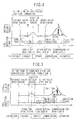
- Fig. 2 is a system configuration when a controller of a compression ignition combustion engine according to an embodiment of the present invention is applied to an automobile gasoline engine.
- An engine 100 is a compression ignition engine that performs spark ignition combustion and compression ignition combustion.
- the engine 100 includes an airflow sensor 1 which measures the amount of intake air and an electronic control throttle 2 which adjusts the intake flow rate, each being provided at a required position in an intake pipe 6.
- the engine 100 includes an injector 3 which injects fuel into a combustion chamber surrounded by a cylinder 7 and a piston 14, an ignition plug 4 which supplies ignition energy, and variable valves 5 (an intake valve 5a which controls intake gas flowing in the cylinder and an exhaust valve 5b which controls exhaust gas discharged therefrom); each being provided at a required position in the cylinder 7.
- the amount of EGR in the cylinder is controlled by controlling the variable valves 5.
- the engine 100 includes a three-way catalyst 10 which purifies exhaust gas, an air-fuel ratio sensor 9 which is one mode of an air-fuel ratio detector and detects an air-fuel ratio of exhaust gas on an upstream side of the three-way catalyst 10, and an exhaust temperature sensor 11 which is one mode of an exhaust temperature detector and measures the temperature of exhaust gas on an upstream side of the three-way catalyst 10; each being provided at a required position in the exhaust pipe 8.
- a crankshaft 12 is provided with a crank angle sensor 13 for calculating the rotational angle. Signals obtained from the airflow sensor 1, the air-fuel ratio sensor 9, the exhaust temperature sensor 11, and the crank angle sensor 13 are sent to a control unit (hereafter referred to as ECU 20).
- ECU 20 control unit
- a signal (not shown in the diagram) obtained from a sensor which detects a requested torque for the engine (hereafter referred to as requested torque detection sensor) is sent to the ECU 20, and a requested torque is calculated based on an output signal of the requested torque detection sensor within the ECU 20.
- the requested torque detection sensor refers to an accelerator opening sensor, for example, in an engine-mounted automobile.
- the ECU 20 calculates the rotational speed of the engine based on an output signal of the crank angle sensor 13. Based on engine operating conditions obtained from outputs of each of the above-mentioned sensors, main operation variables of the engine such as airflow rate, amount of fuel injection, ignition timing, etc. are optimally calculated.
- the amount of fuel injection calculated by the ECU 20 is converted to a valve opening pulse signal and then sent to the injector 3. Further, an ignition plug drive signal is sent to the ignition plug 4 so that the fuel can be ignited at an ignition timing calculated by the ECU 20. Further, a throttle opening calculated by the ECU 20 is sent to the electronic control throttle 2 as a throttle drive signal. Further, the operation amounts of the variable valves calculated by the ECU 20 are sent to the variable valves 5 as variable valve drive signals.
- the ECU 20 also performs combustion of a type different from spark ignition combustion and compression ignition combustion.
- a negative overlap period is provided to leave internal EGR in the cylinder 7.
- the amount of residual EGR is less than that at the time of compression ignition combustion.
- air is channeled into the cylinder 7 through the variable valves 5 from the intake pipe 6, and fuel injection (main fuel injection) is performed to form an air-fuel mixture.
- fuel injection main fuel injection
- the air-fuel mixture explodes by sparks generated by the ignition plug 4 at a predetermined ignition timing.
- a part of the air-fuel mixture not having undergone spark ignition combustion performs compression ignition resulting in an explosion.
- combustion pressure of the explosion depresses the piston to produce a driving power of the engine.
- exhaust gas is purified by the three-way catalyst 10 and then discharged to the outside.
- Such combustion that implements ignition combustion by a pressure rise after the above-mentioned spark ignition combustion is defined as combined combustion.
- An operation of the engine 100 at the time of the combined combustion is outlined in Fig. 5 .
- Fig. 6 shows an internal block diagram of the ECU 20.
- output signals of the airflow sensor 1, the air-fuel ratio sensor 9, the exhaust temperature sensor 11, and the crank angle sensor 13 are inputted to an input circuit 601.
- input signals are not limited thereto.
- the inputted input signals of each sensor are sent to an input port in an input/output port 602.
- Values sent to the input port are stored in a RAM 603 and then subjected to calculation processing by a CPU 605.
- a control program having descriptions of detailed calculation processing is programmed in a ROM 604 in advance.
- a value indicating an amount of operation of each actuator calculated according to the control program is stored in the RAM 603, sent to the output port in the input/output port 602, and sent to each actuator through each drive circuit.
- Drive circuits of the present embodiment include an electronic throttle drive circuit 606, an injector drive circuit 607, an ignition output circuit 608, and a variable valve drive circuit 609. These circuits control the actuation of the electronic control throttle 2, the injector 3, the ignition plug 4, and the variable valves 5, respectively.
- the ECU 20 is provided with a combustion type switching controller 20A which prevents the degradation of operation performance and exhaust performance at the time of combustion type switching between spark ignition combustion and compression ignition combustion.
- a combustion type switching controller 20A which prevents the degradation of operation performance and exhaust performance at the time of combustion type switching between spark ignition combustion and compression ignition combustion.
- the following explains the combustion type switching control between spark ignition combustion and compression ignition combustion by the combustion type switching controller 20A.
- the combustion type switching controller 20A according to the present embodiment performs the combined combustion by controlling an internal cylinder temperature and a combustion speed at the end of compression upon combustion type switching, thus performing a smooth switching between spark ignition combustion and compression ignition combustion. As a result, it is possible to reduce torque fluctuations and an increase in exhaust gas components at the time of combustion type switching.
- Fig. 7 is a control block diagram of combustion type switching control by the combustion type switching controller 20A.
- the combustion type switching controller 20A includes a combustion type switching judgment section 701 and a combustion type switching implementation section 702 which changes operation variables of the engine 100 for combustion type switching.
- the combustion type switching judgment section 701 determines whether or not combustion type switching is possible based on a requested engine torque and a rotational speed required for the engine 100, sets a combustion type switch flag, and outputs the flag to the combustion type switching implementation section 702.
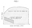
- the combustion type switching judgment section 701 includes a map showing operating conditions of the engine 100 based on an engine torque and an engine rotational speed as shown in Fig. 1 .
- the combustion type switching implementation section 702 determines target operation variables for controlling the engine 100 based on the combustion type switch flag which is an output of the combustion type switching judgment section 701.
- the combustion type switching implementation section 702 sets operation variables for combined combustion to target operation variables to implement combined combustion and then sets operation variables for compression ignition combustion to target operation variables so as to change the combustion type from spark ignition combustion through combined combustion to compression ignition combustion.
- the combustion type switching implementation section 702 sets operation variables for spark ignition combustion to target operation variables so as to perform spark ignition combustion without changing the combustion type to compression ignition combustion.
- the combustion type switching implementation section 702 sets operation variables for combined combustion to target operation variables to implement combined combustion and then sets operation variables for spark ignition combustion to target operation variables so as to change the combustion type from compression ignition combustion through combined combustion to spark ignition combustion.
- the combustion type switching implementation section 702 sets operation variables for compression ignition combustion to target operation variables so as to perform compression ignition combustion without changing the combustion type to compression ignition combustion.
- the above-mentioned operation variables refer to an opening of the electronic control throttle 2 (a throttle opening), a fuel injection pulse width and fuel injection timing of the injector 3, an ignition timing of the ignition plug 4, an opening/closing timing of the intake valve 5a, and an opening/closing timing of the exhaust valve 5b, each being operated when controlling the engine 100.
- combined combustion is completed when combined combustion have been performed for a predetermined time based on the combined combustion detection flag which is an output result of combined combustion detection means, such as a cylinder internal pressure sensor for detecting a pressure in the cylinder 7, a knock sensor, etc. provided in the engine 100.
- Fig. 8 is a time chart of each flag and target value when combustion type switching control is implemented.
- a dashed line shows a case where an operation variable is simply changed (simple switching control) at a time point t1 at the time of switching from spark ignition combustion to compression ignition combustion.
- a solid line shows a case where combustion type switching control according to the present embodiment is applied.
- the time point t1 denotes a timing at which combustion type switching from spark ignition combustion to combined combustion is started
- a time point t2 denotes a timing at which combustion type switching from spark ignition combustion to combined combustion is completed
- a time point t3 denotes a timing at which combustion type switching from combined combustion to compression ignition combustion is started.
- the throttle opening is operated so as to prevent a decrease in an air volume (by an increase in the amount of internal EGR by the increased amount of negative overlap) to maintain the air-fuel ratio to the stoichiometric condition. Further, also at the time point t1 and thereafter, the main fuel injection pulse width is the same as a setup value at the time of spark ignition combustion.
- the ignition timing is made earlier so as to restrain the degradation of combustion stability caused by the increased amount of internal EGR.
- the controller changes the combustion type from combined combustion to compression ignition combustion. For combustion type switching, the controller increases the amount of negative overlap and the throttle opening, starts subfuel injection, and decreases the main fuel injection pulse width. After compression ignition combustion has been implemented, the controller sets the ignition timing to OFF.
- the predetermined time A during which combined combustion is continued is a setup value predetermined in a test or a simulation.
- the predetermined time A may differ according to operating conditions of the engine 100 and may be determined based on an output result of a sensor which detects the combustion type in the cylinder 7.
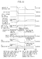
- Fig. 9 is a time chart of each operation variable when combustion type switching control from spark ignition combustion to compression ignition combustion is performed by the combustion type switching controller 20A.
- the time chart shows the amount of internal EGR, the air volume, the total amount of fuel injection, the internal cylinder temperature at the end of compression, the combustion speed at the end of compression, the combustion type, the engine torque, the NOx concentration in exhaust gas components, and the HC concentration therein (For each of the internal EGR, the air volume, the total amount of fuel injection, the combustion speed at the end of compression, the engine torque, the NOx concentration, and the HC concentration, the upward direction means an increase in value. For the internal cylinder temperature at the end of compression, the upward direction means higher temperature. For the combustion type, the upward direction means compression ignition combustion.).
- a dashed line shows a case where the simple switching control is applied
- a solid line shows a case where the combustion type switching control according to the present embodiment is applied.
- the controller changes each operation variable to setup values for implementing compression ignition combustion at the time point t1. Accordingly, the amount of internal EGR and the air volume increase, and the total amount of fuel injection decreases. Thus, compression ignition combustion is implemented, and combustion is started after the end of compression (compression top dead center), thereby reducing the internal cylinder temperature at the end of compression and the combustion speed at the end of compression (The embodiment of Fig. 9 shows a case where the ignition timing of compression ignition combustion is after the end of compression.). However, when each operation variable is simply changed at the same timing, the engine undergoes a cycle with an unstable combustion condition in which neither spark ignition combustion nor compression ignition combustion can be implemented in the cylinder 7.
- combustion type switching controller 20A when combustion type switching control from spark ignition combustion to compression ignition combustion is applied by the combustion type switching controller 20A at the time point t1, the controller increases the amount of internal EGR, but leaves the air volume unchanged by correcting the throttle opening. Further, since the total amount of fuel injection is also the same as that before the time point t1, the air-fuel ratio remains unchanged and is maintained to the stoichiometric condition. Further, the internal cylinder temperature at the end of compression decreases by an increase in the amount of internal EGR, and at the same time the combustion speed at the end of compression decreases. When each value is set as a predetermined value, the combustion type changes to combined combustion at the time point t2.
- the controller performs combined combustion for a predetermined time; then, it increases the amount of internal EGR and the air volume and decreases the total amount of fuel injection so as to change the combustion type to compression ignition combustion at the time t3. Then, compression ignition combustion is implemented. Accordingly, the internal cylinder temperature at the end of compression falls, and at the same time the combustion speed at the end of compression decreases (As mentioned above, Fig. 9 shows a case where the ignition timing at the time of compression ignition combustion is after the compression top dead center.).
- the combustion type can be changed from spark ignition combustion to compression ignition combustion while maintaining combustion stability. Since this can prevent spark and combustion failures at the time of combustion type switching, there are no fluctuations of the engine torque ,and an increase in the NOx concentration and HC concentration can be restrained.
- the controller determines that it is necessary to change the combustion type to spark ignition combustion, and the combustion type switching implementation section 702 sets operation variables for spark ignition combustion to target operation variables so as to implement spark ignition combustion.
- an air-precedent fuel control method is widely applied at the time of spark ignition combustion.
- the controller operates the electronic control throttle 2 which changes the air volume flowing into the cylinder according to a requested engine torque required for the engine and determines the amount of fuel injection so as to maintain the air-fuel ratio close to the stoichiometric condition according to the above-mentioned air volume measured by the airflow sensor 1.
- a fuel-precedent fuel control method is applied at the time of compression ignition combustion. With this method, the amount of fuel injection is determined directly from a requested engine torque in order to perform combustion with the air-fuel ratio maintained to the lean-burn condition.
- the air-precedent combustion control method (not shown in the diagram) is performed at the time of spark ignition combustion before the time point t1 shown in Figs. 8 and 9 , and then the fuel-precedent combustion control method is selected after the time point t1.
- the reason why this fuel control method is used is explained as follows: The air volume fluctuates by variation of the amount of EGR according to variation of valve timing. Then, if the air-precedent fuel control method is applied, the amount of fuel injection fluctuates at the time of combustion type switching to combined combustion or compression ignition combustion after the time point t1, resulting in torque fluctuations. Thus, the above-mentioned fuel control method aims at suppressing the torque fluctuations.
- the air-precedent fuel control method may be performed in combined combustion performed between the time points t1 and t3; then, the fuel-precedent fuel control method may be selected at the time point t3.
- Fig. 10 is a time chart of each flag and target value when the above-mentioned combustion type switching control is performed.
- a dashed line shows a case where target values of each operation variable is simply changed (simple switching control) at a time point t4 at the time of switching from compression ignition combustion to spark ignition combustion.
- a solid line shows a case where the combustion type switching control according to the present embodiment is applied.
- the time point t4 denotes a timing at which combustion type switching from compression ignition combustion to combined combustion is started
- a time point t5 denotes a timing at which combustion type switching from compression ignition combustion to combined combustion is completed
- a time point t6 denotes a timing at which combustion type switching from combined combustion to spark ignition combustion is started.
- the controller decreases the amount of negative overlap and the throttle opening so as to perform combustion type switching from compression ignition combustion to combined combustion at the time point t4.
- the controller operates the amount of negative overlap at the time of combined combustion such that it is less than that at the time of compression ignition combustion and the throttle opening to such an extent that a deviation from the stoichiometric condition can be avoided by decreasing the air volume when the internal EGR is introduced.
- the controller zeros the subfuel injection pulse width, stops subfuel injection, and increases the main fuel injection pulse width at the time point t4.
- the controller sets the ignition signal to ON at the time point t4, i.e., the controller sets an ignition timing which is earlier than that at the time of spark ignition combustion in order to ensure combustion stability at the time of combined combustion.
- the controller decreases the amount of negative overlap and the throttle opening and delays the ignition timing so as to switch the combustion type from combined combustion to spark ignition combustion.
- the predetermined time B during which combined combustion is continued is a setup value predetermined in a test or a simulation.
- Fig. 11 is a time chart of each value when combustion type switching control from compression ignition combustion to spark ignition combustion by the combustion type switching controller 20A is performed.
- the time chart shows the amount of internal EGR, the air volume, the total amount of fuel injection, the internal cylinder temperature at the end of compression, the combustion speed at the end of compression, the combustion type, the engine torque, the NOx concentration in exhaust gas components, and the HC concentration therein (For each of the internal EGR, the air volume, the total amount of fuel injection, the combustion speed at the end of compression, the engine torque, the NOx concentration, and the HC concentration, the upward direction means an increase in value. For the internal cylinder temperature at the end of compression, the upward direction means higher temperature. For the combustion type, the upward direction means compression ignition combustion.).
- a dashed line shows a case where the simple switching control is applied, and a solid line shows a case where the combustion type switching control according to the present embodiment is applied.
- the controller changes each operation variable to setup values for implementing spark ignition combustion at the time point t4. Accordingly, the amount of internal EGR, the air volume, and the total amount of fuel injection decrease.
- spark ignition combustion i.e., the combustion type is changed to spark ignition combustion in which combustion is started by ignition sparks supplied from the ignition plug before the end of compression, the internal cylinder temperature at the end of compression rises, and the combustion speed at the end of compression increases (However, the embodiment of Fig. 11 shows a case where the ignition timing of compression ignition combustion is after the end of compression.).
- the combustion type switching control from compression ignition combustion to spark ignition combustion by the combustion type switching controller 20A when the combustion type switching control from compression ignition combustion to spark ignition combustion by the combustion type switching controller 20A is applied, the amount of internal EGR is decreased so as to change the combustion type from compression ignition combustion to combined combustion at the time point t4.
- the air volume remains unchanged through the correction of the throttle opening; therefore, the air-fuel ratio is maintained to the stoichiometric condition.
- the controller increases the total amount of fuel injection.
- the internal cylinder temperature at the end of compression rises, and at the same time the combustion speed at the end of compression increases.
- the controller performs combined combustion for a predetermined time; then, it decreases the amount of internal EGR, delays the ignition timing, and performs spark ignition combustion so as to change the combustion type to spark ignition combustion at the time point t6. Accordingly, the internal cylinder temperature at the end of compression increases by the decreased amount of internal EGR, and at the same time the combustion speed at the end of compression increases (As mentioned above, Fig. 11 shows a case where the ignition timing at the time of compression ignition combustion is after the compression top dead center.).
- the controller determines that it is necessary to change the combustion type to compression ignition combustion, and the combustion type switching implementation section 702 sets operation variables for compression ignition combustion to target operation variables so as to implement compression ignition combustion.
- the fuel-precedent combustion control method (not shown in the diagram) is performed at the time of combined combustion and compression ignition combustion before the time point t6 shown in Figs. 10 and 11 , and the air-precedent combustion control method is selected after the time point t6.
- the fuel-precedent fuel control method may be performed before the time point t5; then, the air-precedent fuel control method may be performed at the time of combined combustion and compression ignition combustion after the time point t5.
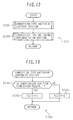
- Figs. 12 to 14 are flow charts of combustion type switching control by the combustion type switching controller 20A.
- Fig. 12 is a flow chart showing the control block of Fig. 7 .
- Step S1202 the combustion type switching controller 20A sets operation variables suitable for the selected combustion type and at the same time changes the operation variables for combustion type switching while restraining the degradation of operation performance and exhaust performance so as to perform combustion of a type according to the combustion type switch flag FLG(t) which denotes a result of Step S1201.
- Fig. 13 is a flow chart of the combustion type switching judgment section in Step S1201.
- the combustion type switching judgment section determines a feasible combustion type based on the map of Fig. 1 according to operating conditions determined by a requested torque and an engine rotational speed. If the operating conditions are such that spark ignition combustion should be performed, the combustion type switching judgment section proceeds to Step S1302; if the operating conditions are such that compression ignition combustion can be performed, the same section proceeds to Step S1303.
- Fig. 14 is a flow chart of a combustion type switching implementation section S1202.
- Step S1406 the combustion type switching implementation section proceeds to Step S1406 so as to continue combined combustion at the time of combustion type switching, change the combustion type from combined combustion to compression ignition combustion, or continue compression ignition combustion.
- Step S1403 determines whether or not operation variables for combined combustion are set as present target operation variables, i.e., whether or not combined combustion is currently being performed or operation variables are currently being operated so as to perform combined combustion. If the present combustion type is combined combustion, the combustion type switching implementation section determines that execution of compression ignition combustion is requested during a combined combustion continuation period and then proceeds to Step S1404. If the present combustion type is not of combined combustion but of spark ignition combustion, the combustion type switching implementation section determines that combustion type switching from spark ignition combustion to compression ignition combustion is requested and then proceeds to Step S1405.
- Step S1404 the combustion type switching implementation section sets operation variables for compression ignition combustion to target operation variables and then terminates a series of the operations so as to perform compression ignition combustion.
- Step S1405 the combustion type switching implementation section sets operation variables for combined combustion to target operation variables and then terminates a series of the operations so as to perform combined combustion during the process of switching from spark ignition combustion to compression ignition combustion.
- Step S1408 the combustion type switching implementation section sets operation variables for compression ignition combustion to target operation variables and then terminates a series of the operations so as to continue compression ignition combustion or change the combustion type from combined combustion to compression ignition combustion.
- Step S1410 determines whether or not the present target operation variables are operation variables for combined combustion. If operation variables for combined combustion are set as present target operation variables, the combustion type switching implementation section proceeds to Step S1412; otherwise, i.e., if operation variables for compression ignition combustion are set, the same section proceeds to Step S1411.
- Step S1411 which is executed when changing the combustion type to compression ignition combustion, sets operation variables for spark ignition combustion to target operation variables and then terminates a series of the operations so as to change the combustion type from compression ignition combustion to spark ignition combustion.
- Step S1412 is executed when combustion type switching to spark ignition combustion is requested during the combined combustion continuation period in the process of combustion type switching to compression ignition combustion. This step sets operation variables for spark ignition combustion to target operation variables and then terminates a series of the operations so as to change the combustion type from combined combustion to spark ignition combustion.
- Step S1413 determines whether or not combined combustion is currently being continued during the process of combustion type switching to spark ignition combustion. If operation variables for combined combustion are set as present target operation variable, i.e., combined combustion is currently being continued, the combustion type switching implementation section proceeds to Step S1414. On the other hand, if operation variables for combined combustion are not set as present target operation variable, i.e., if operation variables for spark ignition combustion are set, the combustion type switching implementation section determines that continuation of spark ignition combustion is requested, proceeds to Step S1412 to set operation variables for spark ignition combustion to target operation variables, and then terminates a series of the operations.
- Step S1415 the combustion type switching implementation section sets operation variables for combined combustion to target operation variables and then terminates a series of the operations so as to continue combined combustion.
- the predetermined time A in the above-mentioned flow chart refers to a time period during which combined combustion is continued during the process of switching from spark ignition combustion to compression ignition combustion, and it is equivalent to a time period between t3 and t1 (t3-t1) of Figs. 8 and 9 .
- the predetermined time B is a time period during which combined combustion is continued during the process of switching from compression ignition combustion to spark ignition combustion, and it is equivalent to a time period between t6 and t4 (t6-t4) of Figs. 10 and 11 .
- the combustion type switching judgment section 701 may determine whether or not switching between spark ignition combustion and compression ignition combustion can be performed based not only on a requested torque and an engine rotational speed but also on at least one of output signals of sensors which directly or indirectly detect a water temperature, an exhaust temperature, an intake temperature, and a fuel temperature.
- combustion control means based on control of the internal EGR to perform compression ignition combustion
- combustion control means based on adjustment of EGR, such as external EGR, or control of an intake temperature, an actual compression ratio, or an intake pipe pressure.
- parameters at the time of combustion type switching are set to predetermined values that enable combined combustion to change the combustion type.
- the predetermined values can be changed based not only on operating conditions but also on a water temperature, an exhaust temperature, an intake temperature, and a fuel temperature, it is possible to use values predetermined through a simulation or an experiment. Further, it is also possible to update the predetermined values through learning during operation.
- the combustion type can smoothly be changed by providing combined combustion in the process of combustion type switching, making it possible to restrain the degradation of operation performance at the time of combustion type switching. Further, since the air-fuel ratio is maintained to the stoichiometric condition in combined combustion, it is also possible to restrain the degradation of exhaust performance at the time of combustion type switching.
Landscapes
- Engineering & Computer Science (AREA)
- Chemical & Material Sciences (AREA)
- Combustion & Propulsion (AREA)
- Mechanical Engineering (AREA)
- General Engineering & Computer Science (AREA)
- Output Control And Ontrol Of Special Type Engine (AREA)
- Combined Controls Of Internal Combustion Engines (AREA)
- Control Of Throttle Valves Provided In The Intake System Or In The Exhaust System (AREA)
- Electrical Control Of Air Or Fuel Supplied To Internal-Combustion Engine (AREA)
- Electrical Control Of Ignition Timing (AREA)
- Combustion Methods Of Internal-Combustion Engines (AREA)
Applications Claiming Priority (1)
| Application Number | Priority Date | Filing Date | Title |
|---|---|---|---|
| JP2006339385A JP4438792B2 (ja) | 2006-12-18 | 2006-12-18 | 圧縮自己着火式内燃機関の制御装置 |
Publications (3)
| Publication Number | Publication Date |
|---|---|
| EP1936168A2 true EP1936168A2 (de) | 2008-06-25 |
| EP1936168A3 EP1936168A3 (de) | 2014-07-16 |
| EP1936168B1 EP1936168B1 (de) | 2017-10-04 |
Family
ID=39085188
Family Applications (1)
| Application Number | Title | Priority Date | Filing Date |
|---|---|---|---|
| EP07021734.4A Ceased EP1936168B1 (de) | 2006-12-18 | 2007-11-08 | Steuergerät für einen Verbrennungsmotor mit Kompressionszündung |
Country Status (3)
| Country | Link |
|---|---|
| US (1) | US7848869B2 (de) |
| EP (1) | EP1936168B1 (de) |
| JP (1) | JP4438792B2 (de) |
Cited By (2)
| Publication number | Priority date | Publication date | Assignee | Title |
|---|---|---|---|---|
| WO2011082918A1 (de) * | 2010-01-08 | 2011-07-14 | Robert Bosch Gmbh | Verfahren zum umschalten zwischen einer hcci-verbrennung und einer si-verbrennung in einem reaktor einer brennkraftmaschine |
| EP3240949A4 (de) * | 2014-12-30 | 2018-08-15 | Robert Bosch GmbH | Fortschrittlicher multimodaler verbrennungsmotor mit überwachungssteuerung |
Families Citing this family (12)
| Publication number | Priority date | Publication date | Assignee | Title |
|---|---|---|---|---|
| DE102008000916B4 (de) * | 2007-04-02 | 2021-12-16 | Denso Corporation | Verbrennungssteuerungsvorrichtung für direkt einspritzende Kompressionszündungskraftmaschine |
| JP4836088B2 (ja) | 2007-11-08 | 2011-12-14 | 日立オートモティブシステムズ株式会社 | 圧縮自己着火式内燃機関の制御装置および制御方法 |
| JP5028245B2 (ja) * | 2007-12-20 | 2012-09-19 | 本田技研工業株式会社 | 内燃機関の内部egr制御装置 |
| JP5303511B2 (ja) * | 2010-06-11 | 2013-10-02 | 日立オートモティブシステムズ株式会社 | 筒内燃料噴射式内燃機関の制御装置 |
| JP5568457B2 (ja) * | 2010-12-20 | 2014-08-06 | 日立オートモティブシステムズ株式会社 | 内燃機関の制御装置 |
| US9228510B2 (en) * | 2012-08-22 | 2016-01-05 | Cummins Inc. | Engine control systems and methods |
| DE112013004385T5 (de) | 2012-09-07 | 2015-05-21 | Mazda Motor Corporation | Fremdzündungsmotor |
| JP5994700B2 (ja) * | 2013-03-25 | 2016-09-21 | マツダ株式会社 | 火花点火式エンジンの制御装置 |
| JP5858971B2 (ja) | 2013-11-18 | 2016-02-10 | 三菱電機株式会社 | 内燃機関の制御装置およびその方法 |
| WO2018096586A1 (ja) * | 2016-11-22 | 2018-05-31 | マツダ株式会社 | 圧縮自己着火式エンジンの制御装置 |
| WO2018096587A1 (ja) * | 2016-11-22 | 2018-05-31 | マツダ株式会社 | 圧縮自己着火式エンジンの制御装置 |
| US10018142B1 (en) * | 2017-02-10 | 2018-07-10 | GM Global Technology Operations LLC | Auxiliary fuel injector timing driver |
Citations (5)
| Publication number | Priority date | Publication date | Assignee | Title |
|---|---|---|---|---|
| JPH11336600A (ja) * | 1998-05-22 | 1999-12-07 | Nissan Motor Co Ltd | 火花点火式内燃機関 |
| JP2000192828A (ja) * | 1998-12-25 | 2000-07-11 | Nissan Motor Co Ltd | 内燃機関の燃焼制御装置 |
| US6237562B1 (en) * | 1999-01-29 | 2001-05-29 | Honda Giken Kogyo Kabushiki Kaisha | Method of controlling compression ignition internal combustion engine |
| EP1298292A2 (de) * | 2001-09-28 | 2003-04-02 | Hitachi, Ltd. | Regler für eine verdichtungsgezündete Maschine |
| EP1310649A1 (de) * | 2000-08-17 | 2003-05-14 | Hitachi, Ltd. | Dieselbrennkraftmaschine |
Family Cites Families (9)
| Publication number | Priority date | Publication date | Assignee | Title |
|---|---|---|---|---|
| DE19923413B4 (de) | 1999-05-21 | 2011-02-17 | Daimler Ag | Verfahren zum Betrieb einer im Viertakt arbeitenden Hubkolben-Brennkraftmaschine mit wechselnder Kompressions- und Fremdzündung |
| JP3911912B2 (ja) | 1999-06-23 | 2007-05-09 | 株式会社日立製作所 | エンジン制御システム及び制御方法 |
| US6752104B2 (en) * | 2001-12-11 | 2004-06-22 | Caterpillar Inc | Simultaneous dual mode combustion engine operating on spark ignition and homogenous charge compression ignition |
| US20040182359A1 (en) * | 2003-03-17 | 2004-09-23 | Stewart Daniel W. | Individual cylinder-switching in a multi-cylinder engine |
| JP2004293471A (ja) | 2003-03-27 | 2004-10-21 | Honda Motor Co Ltd | 燃焼方式切替可能な内燃機関の吸気絞り弁制御装置 |
| JP4386781B2 (ja) | 2004-03-31 | 2009-12-16 | 大阪瓦斯株式会社 | エンジン |
| JP4100401B2 (ja) | 2005-02-24 | 2008-06-11 | トヨタ自動車株式会社 | 内燃機関 |
| US7240659B2 (en) * | 2005-09-21 | 2007-07-10 | Ford Global Technologies, Llc | Transition strategy for engine operation with spark ignition and homogeneous charge compression ignition modes |
| JP2007247479A (ja) * | 2006-03-15 | 2007-09-27 | Hitachi Ltd | 圧縮着火式内燃機関の制御装置 |
-
2006
- 2006-12-18 JP JP2006339385A patent/JP4438792B2/ja not_active Expired - Fee Related
-
2007
- 2007-11-08 EP EP07021734.4A patent/EP1936168B1/de not_active Ceased
- 2007-12-12 US US11/954,417 patent/US7848869B2/en not_active Expired - Fee Related
Patent Citations (5)
| Publication number | Priority date | Publication date | Assignee | Title |
|---|---|---|---|---|
| JPH11336600A (ja) * | 1998-05-22 | 1999-12-07 | Nissan Motor Co Ltd | 火花点火式内燃機関 |
| JP2000192828A (ja) * | 1998-12-25 | 2000-07-11 | Nissan Motor Co Ltd | 内燃機関の燃焼制御装置 |
| US6237562B1 (en) * | 1999-01-29 | 2001-05-29 | Honda Giken Kogyo Kabushiki Kaisha | Method of controlling compression ignition internal combustion engine |
| EP1310649A1 (de) * | 2000-08-17 | 2003-05-14 | Hitachi, Ltd. | Dieselbrennkraftmaschine |
| EP1298292A2 (de) * | 2001-09-28 | 2003-04-02 | Hitachi, Ltd. | Regler für eine verdichtungsgezündete Maschine |
Non-Patent Citations (1)
| Title |
|---|
| FUERHAPTER A ET AL: "HOMOGENE SELBSTZUENDUNG DIE PRAKTISCHE UMSETZUNG AM TRANSIENTEN VOLLMOTOR", MTZ MOTORTECHNISCHE ZEITSCHRIFT, VIEWEG VERLAG, WIESBADEN, DE, vol. 65, no. 2, 1 February 2004 (2004-02-01), pages 94-101, XP001198707, ISSN: 0024-8525 * |
Cited By (3)
| Publication number | Priority date | Publication date | Assignee | Title |
|---|---|---|---|---|
| WO2011082918A1 (de) * | 2010-01-08 | 2011-07-14 | Robert Bosch Gmbh | Verfahren zum umschalten zwischen einer hcci-verbrennung und einer si-verbrennung in einem reaktor einer brennkraftmaschine |
| EP3240949A4 (de) * | 2014-12-30 | 2018-08-15 | Robert Bosch GmbH | Fortschrittlicher multimodaler verbrennungsmotor mit überwachungssteuerung |
| US10550790B2 (en) | 2014-12-30 | 2020-02-04 | Robert Bosch Llc | Multi-mode advanced combustion engine with supervisory control |
Also Published As
| Publication number | Publication date |
|---|---|
| US7848869B2 (en) | 2010-12-07 |
| EP1936168B1 (de) | 2017-10-04 |
| JP4438792B2 (ja) | 2010-03-24 |
| EP1936168A3 (de) | 2014-07-16 |
| JP2008151021A (ja) | 2008-07-03 |
| US20080147300A1 (en) | 2008-06-19 |
Similar Documents
| Publication | Publication Date | Title |
|---|---|---|
| EP1936168B1 (de) | Steuergerät für einen Verbrennungsmotor mit Kompressionszündung | |
| JP4836088B2 (ja) | 圧縮自己着火式内燃機関の制御装置および制御方法 | |
| US7957887B2 (en) | Engine controller | |
| US8050846B2 (en) | Apparatus and method for controlling engine | |
| US7367310B2 (en) | Controller for compression ignition engine | |
| US7628013B2 (en) | Control device of charge compression ignition-type internal combustion engine | |
| KR20060051868A (ko) | 엔진 | |
| US20090078235A1 (en) | Control System and Method for Internal Combustion Engine | |
| JP6424067B2 (ja) | エンジン制御装置 | |
| JP5055245B2 (ja) | 圧縮自己着火式内燃機関の制御装置 | |
| US8261755B2 (en) | Fuel injection system of compression ignition internal combustion engine | |
| US8464687B2 (en) | Control device for compressed self-ignition type internal combustion engine | |
| JP2007064210A (ja) | 圧縮着火内燃機関の制御装置 | |
| JP5087569B2 (ja) | 圧縮自己着火式内燃機関の制御装置 | |
| US10837418B2 (en) | Internal combustion engine control device | |
| JP2008075633A (ja) | 内燃機関の燃焼制御装置 | |
| JP2007040235A (ja) | 圧縮着火内燃機関の制御装置 | |
| JP6527393B2 (ja) | 内燃機関の制御装置 | |
| JP2005098186A (ja) | 内燃機関の運転領域制御装置 | |
| JP2005098187A (ja) | 内燃機関の制御装置 |
Legal Events
| Date | Code | Title | Description |
|---|---|---|---|
| PUAI | Public reference made under article 153(3) epc to a published international application that has entered the european phase |
Free format text: ORIGINAL CODE: 0009012 |
|
| AK | Designated contracting states |
Kind code of ref document: A2 Designated state(s): AT BE BG CH CY CZ DE DK EE ES FI FR GB GR HU IE IS IT LI LT LU LV MC MT NL PL PT RO SE SI SK TR |
|
| AX | Request for extension of the european patent |
Extension state: AL BA HR MK RS |
|
| 17P | Request for examination filed |
Effective date: 20090623 |
|
| PUAL | Search report despatched |
Free format text: ORIGINAL CODE: 0009013 |
|
| AK | Designated contracting states |
Kind code of ref document: A3 Designated state(s): AT BE BG CH CY CZ DE DK EE ES FI FR GB GR HU IE IS IT LI LT LU LV MC MT NL PL PT RO SE SI SK TR |
|
| AX | Request for extension of the european patent |
Extension state: AL BA HR MK RS |
|
| RIC1 | Information provided on ipc code assigned before grant |
Ipc: F02D 41/30 20060101AFI20140611BHEP Ipc: F02D 13/02 20060101ALN20140611BHEP Ipc: F02B 1/12 20060101ALI20140611BHEP |
|
| AKX | Designation fees paid |
Designated state(s): DE |
|
| AXX | Extension fees paid |
Extension state: MK Extension state: RS Extension state: AL Extension state: HR Extension state: BA |
|
| 17Q | First examination report despatched |
Effective date: 20150330 |
|
| GRAP | Despatch of communication of intention to grant a patent |
Free format text: ORIGINAL CODE: EPIDOSNIGR1 |
|
| RIC1 | Information provided on ipc code assigned before grant |
Ipc: F02B 75/12 20060101ALI20170306BHEP Ipc: F02D 41/00 20060101ALI20170306BHEP Ipc: F02B 23/10 20060101ALI20170306BHEP Ipc: F02M 26/01 20160101ALI20170306BHEP Ipc: F02D 41/40 20060101ALI20170306BHEP Ipc: F02D 41/30 20060101AFI20170306BHEP Ipc: F02D 13/02 20060101ALN20170306BHEP Ipc: F02B 1/12 20060101ALI20170306BHEP |
|
| STAA | Information on the status of an ep patent application or granted ep patent |
Free format text: STATUS: GRANT OF PATENT IS INTENDED |
|
| RIC1 | Information provided on ipc code assigned before grant |
Ipc: F02B 1/12 20060101ALI20170316BHEP Ipc: F02D 13/02 20060101ALN20170316BHEP Ipc: F02B 23/10 20060101ALI20170316BHEP Ipc: F02D 41/00 20060101ALI20170316BHEP Ipc: F02B 75/12 20060101ALI20170316BHEP Ipc: F02D 41/40 20060101ALI20170316BHEP Ipc: F02D 41/30 20060101AFI20170316BHEP Ipc: F02M 26/01 20160101ALI20170316BHEP |
|
| INTG | Intention to grant announced |
Effective date: 20170413 |
|
| GRAA | (expected) grant |
Free format text: ORIGINAL CODE: 0009210 |
|
| GRAS | Grant fee paid |
Free format text: ORIGINAL CODE: EPIDOSNIGR3 |
|
| STAA | Information on the status of an ep patent application or granted ep patent |
Free format text: STATUS: THE PATENT HAS BEEN GRANTED |
|
| AK | Designated contracting states |
Kind code of ref document: B1 Designated state(s): DE |
|
| RIN1 | Information on inventor provided before grant (corrected) |
Inventor name: YAMAOKA, SHIRO Inventor name: KAKUYA, HIROMU Inventor name: KUMANO, KENGO |
|
| RIN2 | Information on inventor provided after grant (corrected) |
Inventor name: KUMANO, KENGO Inventor name: YAMAOKA, SHIRO Inventor name: KAKUYA, HIROMU |
|
| REG | Reference to a national code |
Ref country code: DE Ref legal event code: R096 Ref document number: 602007052547 Country of ref document: DE |
|
| REG | Reference to a national code |
Ref country code: DE Ref legal event code: R097 Ref document number: 602007052547 Country of ref document: DE |
|
| PLBE | No opposition filed within time limit |
Free format text: ORIGINAL CODE: 0009261 |
|
| STAA | Information on the status of an ep patent application or granted ep patent |
Free format text: STATUS: NO OPPOSITION FILED WITHIN TIME LIMIT |
|
| 26N | No opposition filed |
Effective date: 20180705 |
|
| PGFP | Annual fee paid to national office [announced via postgrant information from national office to epo] |
Ref country code: DE Payment date: 20201028 Year of fee payment: 14 |
|
| REG | Reference to a national code |
Ref country code: DE Ref legal event code: R119 Ref document number: 602007052547 Country of ref document: DE |
|
| PG25 | Lapsed in a contracting state [announced via postgrant information from national office to epo] |
Ref country code: DE Free format text: LAPSE BECAUSE OF NON-PAYMENT OF DUE FEES Effective date: 20220601 |