EP1929225B2 - Auszugkasten für ein kältegerät - Google Patents
Auszugkasten für ein kältegerät Download PDFInfo
- Publication number
- EP1929225B2 EP1929225B2 EP06793663.3A EP06793663A EP1929225B2 EP 1929225 B2 EP1929225 B2 EP 1929225B2 EP 06793663 A EP06793663 A EP 06793663A EP 1929225 B2 EP1929225 B2 EP 1929225B2
- Authority
- EP
- European Patent Office
- Prior art keywords
- refrigeration appliance
- ribs
- elevations
- appliance according
- drawer box
- Prior art date
- Legal status (The legal status is an assumption and is not a legal conclusion. Google has not performed a legal analysis and makes no representation as to the accuracy of the status listed.)
- Active
Links
Images
Classifications
-
- F—MECHANICAL ENGINEERING; LIGHTING; HEATING; WEAPONS; BLASTING
- F25—REFRIGERATION OR COOLING; COMBINED HEATING AND REFRIGERATION SYSTEMS; HEAT PUMP SYSTEMS; MANUFACTURE OR STORAGE OF ICE; LIQUEFACTION SOLIDIFICATION OF GASES
- F25D—REFRIGERATORS; COLD ROOMS; ICE-BOXES; COOLING OR FREEZING APPARATUS NOT OTHERWISE PROVIDED FOR
- F25D25/00—Charging, supporting, and discharging the articles to be cooled
- F25D25/02—Charging, supporting, and discharging the articles to be cooled by shelves
- F25D25/024—Slidable shelves
- F25D25/025—Drawers
-
- A—HUMAN NECESSITIES
- A47—FURNITURE; DOMESTIC ARTICLES OR APPLIANCES; COFFEE MILLS; SPICE MILLS; SUCTION CLEANERS IN GENERAL
- A47B—TABLES; DESKS; OFFICE FURNITURE; CABINETS; DRAWERS; GENERAL DETAILS OF FURNITURE
- A47B2210/00—General construction of drawers, guides and guide devices
- A47B2210/03—Drawers with profiled bottoms
-
- A—HUMAN NECESSITIES
- A47—FURNITURE; DOMESTIC ARTICLES OR APPLIANCES; COFFEE MILLS; SPICE MILLS; SUCTION CLEANERS IN GENERAL
- A47B—TABLES; DESKS; OFFICE FURNITURE; CABINETS; DRAWERS; GENERAL DETAILS OF FURNITURE
- A47B2210/00—General construction of drawers, guides and guide devices
- A47B2210/06—Drawer liners
-
- A—HUMAN NECESSITIES
- A47—FURNITURE; DOMESTIC ARTICLES OR APPLIANCES; COFFEE MILLS; SPICE MILLS; SUCTION CLEANERS IN GENERAL
- A47B—TABLES; DESKS; OFFICE FURNITURE; CABINETS; DRAWERS; GENERAL DETAILS OF FURNITURE
- A47B2210/00—General construction of drawers, guides and guide devices
- A47B2210/17—Drawers used in connection with household appliances
- A47B2210/175—Refrigerators or freezers
-
- F—MECHANICAL ENGINEERING; LIGHTING; HEATING; WEAPONS; BLASTING
- F25—REFRIGERATION OR COOLING; COMBINED HEATING AND REFRIGERATION SYSTEMS; HEAT PUMP SYSTEMS; MANUFACTURE OR STORAGE OF ICE; LIQUEFACTION SOLIDIFICATION OF GASES
- F25D—REFRIGERATORS; COLD ROOMS; ICE-BOXES; COOLING OR FREEZING APPARATUS NOT OTHERWISE PROVIDED FOR
- F25D21/00—Defrosting; Preventing frosting; Removing condensed or defrost water
- F25D21/14—Collecting or removing condensed and defrost water; Drip trays
-
- F—MECHANICAL ENGINEERING; LIGHTING; HEATING; WEAPONS; BLASTING
- F25—REFRIGERATION OR COOLING; COMBINED HEATING AND REFRIGERATION SYSTEMS; HEAT PUMP SYSTEMS; MANUFACTURE OR STORAGE OF ICE; LIQUEFACTION SOLIDIFICATION OF GASES
- F25D—REFRIGERATORS; COLD ROOMS; ICE-BOXES; COOLING OR FREEZING APPARATUS NOT OTHERWISE PROVIDED FOR
- F25D2500/00—Problems to be solved
- F25D2500/02—Geometry problems
Definitions
- the present invention relates to a refrigerator.
- Pull-out boxes are often used in a compartment of the interior of refrigerators which is partitioned off by an intermediate floor, in order to store water-containing refrigerated goods such as, in particular, fruit or vegetables which would quickly release moisture in the interior if unprotected.
- Such a release of moisture is undesirable since it affects the quality of the refrigerated goods and the moisture condenses on the evaporator of the refrigeration device, from where it has to be removed again with the expenditure of energy.
- the storage of such refrigerated goods in a separate volume, as is created by the pull-out box and possibly the intermediate shelf, means that the moisture inevitably released by the refrigerated goods can only escape from the pull-out box with difficulty.
- Free water can collect on the contact surfaces of stored fruit with each other and with the pull-out box and form a breeding ground for bacteria and mold, which also affects the quality and shelf life of the refrigerated goods. In order to counteract this, the pull-out box has to be cleaned frequently.
- JP 2000180043 It is proposed to cover a storage plate of a pull-out box with a protective film made of elastic material, which is provided with a multiplicity of hollow elevations.
- the bumps are pressed flat under the weight of a fruit placed on top, thereby preventing the fruits from rolling away and bumping against each other when the pull-out box is pulled out and pushed in. So it is possible to place the fruits permanently so that they do not touch each other.
- the flexible film creates a very large contact area on the underside of the fruit, which in turn is not conducive to their durability. It is also tedious to clean the flexible film, as it cannot be placed in a dishwasher like a piece of crockery.
- a pull-out box is out JP2001330366 A known.
- the object of the present invention is to provide a refrigeration device which effectively protects sensitive refrigerated goods from spoilage, is easy to clean and is simple to produce with little material.
- the object is achieved by a refrigeration device with the features of claim 1. Because the elevations are made hard, they do not enlarge the contact area between themselves and the refrigerated goods placed thereon by their own deformation. In order to secure fruit or round containers against rolling away, the dimensions of the elevations and / or their distances from one another in the horizontal direction must be of a similar magnitude as the dimensions of the refrigerated goods to be stored thereon. To form such a height structure only on the upper side of the storage plate would require a high expenditure of material and raise manufacturing difficulties, which is why there are recesses on the underside of the supporting plate which are complementary to the elevations.
- the storage plate is itself the base plate of the pull-out box
- the storage plate is removably placed on a base plate of the pull-out box.
- the storage plate is preferably provided with bores between the elevations through which liquid collected on the upper side of the storage plate can flow out in an intermediate space between the base plate and the storage plate, which is formed at least by the complementary recesses.
- the surveys are arranged in a periodic pattern.
- the elevations can be elongated ribs.
- These ribs are preferably separated from the walls of the pull-out box by a trench. Such a trench facilitates cleaning of the storage plate, since moisture or dirt that has collected between the elevations can be wiped into the trench and removed from there.
- the trench is preferably deeper than grooves extending between the ribs.
- the ribs are preferably staggered in the width direction or in the depth direction of the pull-out box, in order to enable space-saving storage of cylindrical refrigerated goods.
- the ribs can prevent refrigerated goods of cylindrical shape from rolling away, but not those of spherical shape.
- the storage plate in successive parallel sectional planes preferably has a corrugated cross section with a fluctuating mean level or with a fluctuating amplitude of the waves.
- the elevations must not have any sharp edges in order not to damage sensitive refrigerated goods.
- the ribs preferably have radii of curvature of not less than 1 cm.
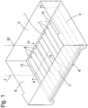
- Fig. 1 shows a perspective view of a pull-out box made of a clear plastic by injection molding according to a first embodiment.
- the box has a base plate 1, which is surrounded by vertical walls 2, 3, 4, 5.
- an elongated handle recess 6 is formed at an edge at which the front wall 2 and the base plate 1 meet.
- a multiplicity of ribs 7 which are uniformly curved in cross section are formed in the base plate 1.
- the ribs 7 extend parallel in the depth direction of the base plate 1.
- the ridges of adjacent ribs 7 are spaced between 1 and 5 cm, and the difference in height between the ridges and the deepest point of a groove 8 between two ribs 7 contributes several mm.
- Rib spacing and height difference are matched to one another in such a way that a round object 9 of several cm in diameter, such as a lying bottle, an apple or a tomato, touches two adjacent ribs 7 near their ridges, but not the bottom of the groove 8 between them Ribs 7.
- the contact area between the object 9 and the base plate 1 thus remains small and moisture can be absorbed by the grooves 8 without coming into contact with the object 9.
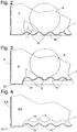
- the ribs 7 have a cross section in the form of an arc of a circle with the convex side pointing upwards, i.e. H. with center of curvature below the base plate 1.
- the grooves 8, however, are formed by upward concave arcs with the same radius of curvature r as the ribs 7.
- the radii of curvature of ribs 7 and grooves 8 can differ. So it can e.g. For example, it may be desirable to give the grooves a smaller radius of curvature than the rib to prevent small items of chilled goods, e.g. Grapes touching the bottom of the grooves.
- the radius of curvature can also vary across the cross-section of a rib. However, it should not be too small, preferably not less than one centimeter, in order to prevent the ribs 7 from being pressed into sensitive refrigerated goods.
- the wall thickness of the base plate 1 is constant over its entire extent, i. H.
- recesses 10 complementary to the ribs 7 are formed on the underside of the base plate 1.
- the height difference between the ridges of the ribs 7 and the bottoms of the grooves 8 is several mm and is greater than the wall thickness of the bottom plate 1.
- the ribs 7 do not extend to the front wall 2 and the rear wall 4, instead a trench 11 running transversely to the ribs is formed between the ends of the ribs 7 and the walls 2, 4. This trench 11 facilitates cleaning of the base plate 1, since residues from the grooves 8 can be quickly and easily wiped into one of the trenches 11 and removed from there together.
- the trenches 11 can be arranged deeper than the grooves 8. Thus, liquid can flow out of the grooves 8 into the trenches 11.
- a trench 12 is expediently formed along the side walls 3, 5 at the same level as the trenches 11, as in FIG Fig. 3 shown.
- Fig. 4 can be understood here both as a cut in the width direction of the pull-out box, as indicated by lines II, II, and as a cut in the depth direction, as indicated by lines IV, IV.
- the profiles of the base plate designated here by 1 'in the two cutting directions do not differ from one another.
- the cut of the Fig. 4 runs through the local depressions 14 and through saddle points 15 between two peaks 13 lying in front of and behind the cutting plane.
- One to the cutting plane of the Fig. 4 parallel section through the tips 13 would a course of the bottom plate 1 'similar to that in Fig. 3 shown with an average higher soil level than in Fig. 4 ,
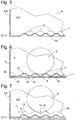
- the cut plane shown corresponds to a value of the depth coordinate y at which f (y) is minimal and negative; the course of a cut along a plane in which f (y) is maximum and positive is easily imaginable on the basis of the contour denoted by 16.
- Fig. 6 shows a modification of the Fig. 1 . 2 , in which the ribs 7 and grooves 8 are formed not in the base plate of the pull-out box itself, but in a plate 17 loosely inserted in the box, while the base plate 1 "'is itself flat.
- the plate 17 can be easily removed and cleaned, so that cleaning of the complete pull-out box is less necessary.
- the insert plate 17 can cover the entire base plate 1 "" of the pull-out box.
- the plate 17 is provided on its underside with isolated knobs 18, which are supported selectively on the base plate 1 "'. Preventing a flat contact between the insert plate 17 and the base plate 1"' ensures that the insert plate 17 is then also light can be removed when moisture has penetrated between them and the base plate 1 "'.
- the height profile in the width and depth directions can also be modulated, as with reference to FIG Figures 4 . 5 described.
- bores 19 are formed in the insert plate 17, through which moisture that flows into one of the depressions 14 can pass into an intermediate space 20 between the insert plate 17 and the base plate 1 "'and is thus kept away from the refrigerated goods ,
Landscapes
- Engineering & Computer Science (AREA)
- Chemical & Material Sciences (AREA)
- Combustion & Propulsion (AREA)
- Physics & Mathematics (AREA)
- Mechanical Engineering (AREA)
- Thermal Sciences (AREA)
- General Engineering & Computer Science (AREA)
- Cold Air Circulating Systems And Constructional Details In Refrigerators (AREA)
- Devices That Are Associated With Refrigeration Equipment (AREA)
- Packging For Living Organisms, Food Or Medicinal Products That Are Sensitive To Environmental Conditiond (AREA)
- Drawers Of Furniture (AREA)
Description
- Die vorliegende Erfindung betrifft ein Kältegerät. Auszugkästen werden häufig in einem durch einen Zwischenboden abgeteilten Fach des Innenraums von Kühlschränken eingesetzt, um dort wasserhaltiges Kühlgut wie insbesondere Obst zu oder Gemüse zu lagern, das bei ungeschützter Lagerung in dem Innenraum schnell Feuchtigkeit abgeben würde. Eine solche Feuchtigkeitsabgabe ist unerwünscht, da sie die Qualität des Kühlguts beeinträchtigt und die Feuchtigkeit am Verdampfer des Kältegeräts kondensiert, von wo sie unter Energieaufwand wieder beseitigt werden muss.
- Die Unterbringung von derartigem Kühlgut in einem abgetrennten Volumen, wie es durch den Auszugkasten und gegebenenfalls den Zwischenboden geschaffen wird, führt jedoch dazu, dass die von dem Kühlgut unvermeidlicherweise abgegebene Feuchtigkeit aus dem Auszugkasten nur schlecht entweichen kann. So kann sich freies Wasser an Kontaktflächen gelagerter Früchte untereinander und mit dem Auszugkasten sammeln und einen Nährboden für Bakterien und Schimmelpilze bilden, was ebenfalls Qualität und Haltbarkeit des Kühlguts beeinträchtigt. Um mit dem entgegenzuwirken, muss der Auszugkasten häufig gereinigt werden.
- Um den Reinigungsprozess zu vereinfachen und die Zeitspanne zwischen zwei Reinigungsvorgängen zu verlängern, legen viele Benutzer den Boden eines solchen Auszugkastens mit saugfähigem Papier aus. Das Papier hilft zwar, Feuchtigkeit aus der unmittelbaren Kontaktzone der Früchte mit dem Boden des Auszugkastens abzuführen, das Wachstum von Keimen kann es jedoch nicht verhindern. Außerdem ist es nicht möglich, mit Hilfe eines solchen Papiers zu verhindern, dass empfindliche Früchte sich gegenseitig berühren.
- Um die Ansammlung von Feuchtigkeit zwischen einer Ablageplatte eines Auszugkastens und auf dieser Ablageplatte gelagertem Kühlgut zu verhindern, wurde in
DE 203 13 431 U1 vorgeschlagen, den Boden einer solchen Ablageplatte mit Belüftungslöchern zu versehen und die von dem Kühlgut berührte Oberseite der Trageplatte mit einer Riffelung zu versehen. An Stelle einer großen zusammenhängenden Kontaktfläche zwischen Kühlgut und Ablageplatte werden so viele kleine Kontaktflächen geschaffen, die jeweils durch Vertiefungen der Riffelung voneinander getrennt sind. Durch die Vertiefungen der Riffelung kann zwar Luft an die Unterseite des Kühlguts gelangen, doch ist der Luftaustausch gering, sodass die Wirkung begrenzt ist. Die Riffelung kann auch nicht verhindern, dass Früchte beim Bewegen des Auszugkastens ins Rollen geraten und gegeneinander oder die Kastenwände stoßen bzw. in einen engen Kontakt miteinander oder den Kastenwänden geraten. - In
JP 2000180043 - Ein Auszugkasten ist aus
JP2001330366 A - Aufgabe der vorliegenden Erfindung ist, ein Kältegerät zu schaffen, das empfindliches Kühlgut wirksam vor Verderb schützt, einfach zu reinigen ist und mit geringem Materialaufwand einfach herstellbar ist.
- Die Aufgabe wird gelöst durch Kältegerät mit den Merkmalen des Anspruchs 1. Indem die Erhebungen hart gemacht sind, vergrößern sie nicht durch eigene Verformung die Kontaktfläche zwischen sich und darauf abgelegtem Kühlgut. Um Früchte oder runde Behälter gegen Wegrollen zusichern, müssen die Abmessungen der Erhebungen und/oder ihre Abstände voneinander in horizontaler Richtung von ähnlicher Größenordnung wie die Abmessungen des darauf zu lagernden Kühlguts sein. Eine solche Höhenstruktur nur an der Oberseite der Ablageplatte zu bilden, würde einen hohen Materialaufwand erfordern und fertigungstechnische Schwierigkeiten aufwerfen, weswegen zu den Erhebungen komplementäre Aussparungen an der Unterseite der Trageplatte vorgesehen sind.
- Einer ersten Ausgestaltung zufolge ist die Ablageplatte selbst Bodenplatte des Auszugkastens,
- Einer weiteren Ausgestaltung zufolge ist die Ablageplatte entfernbar auf einer Bodenplatte des Auszugkastens platziert.
- In diesem Fall ist die Ablageplatte vorzugsweise zwischen den Erhebungen mit Bohrungen versehen, durch die an der Oberseite der Ablageplatte gesammelte Flüssigkeit in einem Zwischenraum zwischen der Bodenplatte und der Ablageplatte abfließen kann, der wenigstens durch die komplementären Aussparungen gebildet ist.
- Die Erhebungen sind in einem periodischen Muster angeordnet.
- Bei den Erhebungen kann es sich um lang gestreckte Rippen handeln.
- Diese Rippen sind vorzugsweise von den Wänden des Auszugkastens durch einen Graben getrennt. Ein solcher Graben erleichtert die Reinigung der Ablageplatte, da Feuchtigkeit oder Schmutz, der sich zwischen den Erhebungen gesammelt hat, in den Graben gewischt und von dort entfernt werden kann.
- Um gegebenenfalls auch ein Abfließen von Flüssigkeit zu ermöglichen, liegt der Graben vorzugsweise tiefer als sich zwischen den Rippen erstreckende Rillen.
- Die Rippen sind vorzugsweise in Breitenrichtung oder in Tiefenrichtung des Auszugkastens gestaffelt, um eine Platz sparende Lagerung von walzenförmigem Kühlgut zu ermöglichen.
- Die Rippen können zwar Kühlgut von walzenförmiger Gestalt an Wegrollen hindern, nicht aber solches von kugeliger Gestalt. Um dies zu erreichen, weist die Ablageplatte in aufeinanderfolgenden parallelen Schnittebenen vorzugsweise einen gewellten Querschnitt mit schwankendem mittleren Niveau oder mit schwankender Amplitude der Wellen auf.
- Selbstverständlich dürfen die Erhebungen keine scharfen Kanten aufweisen, um nicht ihrerseits empfindliches Kühlgut zu beschädigen. Um empfindliches Kühlgut zu schonen, haben die Rippen vorzugsweise Krümmungsradien von nicht weniger als 1 cm.
- Weitere Merkmale und Vorteile der Erfindung ergeben sich aus der nachfolgenden Beschreibung von Ausführungsbeispielen unter Bezugnahme auf die beigefügten Figuren. Es zeigen:
- Fig. 1
- eine perspektivische Ansicht eines Auszugkastens gemäß einer ersten Ausgestaltung
- Fig. 2
- einen fragmentarischen Schnitt durch den Auszugkasten von
Fig. 1 entlang der durch Linien II, II inFig. 1 bezeichneten Ebene; - Fig. 3
- einen zu
Fig. 2 analogen Schnitt gemäß einer zweiten Ausgestaltung; - Fig. 4
- einen zu
Fig. 2 analogen Schnitt bzw. einen Schnitt entlang der inFig. 1 durch Linien IV, IV bezeichneten Ebene gemäß einer dritten Ausgestaltung; - Fig. 5
- einen zu
Fig. 4 analogen Schnitt gemäß einer vierten Ausgestaltung; - Fig. 6
- einen zu
Fig. 2 analogen Schnitt gemäß einer fünften Ausgestaltung; und - Fig. 7
- einen zu
Fig. 4 analogen Schnitt gemäß einer sechsten Ausgestaltung. -
Fig. 1 zeigt eine perspektivische Ansicht eines aus einem glasklaren Kunststoff im Spritzguss gefertigten Auszugkastens gemäß einer ersten Ausgestaltung. Der Kasten hat eine Bodenplatte 1, die von vertikalen Wänden 2, 3, 4, 5 umgeben ist. An einer Kante, an der die vordere Wand 2 und die Bodenplatte 1 aneinander stoßen, ist eine lang gestreckte Griffnische 6 gebildet. In der Bodenplatte 1 ist eine Vielzahl von im Querschnitt gleichmäßig geschwungenen Rippen 7 gebildet. Die Rippen 7 erstrecken sich parallel in Tiefenrichtung der Bodenplatte 1. Die Kämme von benachbarten Rippen 7 haben einen Abstand von zwischen 1 und 5 cm, und der Höhenunterschied zwischen den Kämmen und der tiefsten Stelle einer Rille 8 zwischen zwei Rippen 7 beiträgt mehrere mm. Rippenabstand und Höhenunterschied sind so aneinander angepasst, dass ein runder Gegenstand 9 von mehreren cm Durchmesser wie etwa eine liegende Flasche, ein Apfel oder eine Tomate, zwei benachbarte Rippen 7 in der Nähe von deren Kämmen berührt, nicht aber den Boden der Rille 8 zwischen den Rippen 7. So bleibt die Kontaktfläche zwischen dem Gegenstand 9 und der Bodenplatte 1 klein, und Feuchtigkeit kann von den Rillen 8 aufgenommen werden, ohne mit dem Gegenstand 9 in Kontakt zu geraten. - In dem gezeigten Ausführungsbeispiel haben die Rippen 7 einen Querschnitt in Form eines Kreisbogens mit nach oben gerichteter konvexer Seite, d. h. mit Krümmungsmittelpunkt unterhalb der Bodenplatte 1. Die Rillen 8 hingegen sind durch nach oben konkave Kreisbögen mit dem gleichen Krümmungsradius r wie die Rippen 7 gebildet.
- Selbstverständlich können die Krümmungsradien von Rippen 7 und Rillen 8 sich unterscheiden. So kann es z. B. wünschenswert sein, den Rillen einen kleineren Krümmungsradius als den Rippe, um zu verhindern, dass kleinteiliges Kühlgut, z.B. Trauben, den Boden der Rillen berührt. Es kann auch der Krümmungsradius über den Querschnitt einer Rippe hinweg variieren. Er sollte jedoch nicht zu klein gewählt sein, vorzugsweise nicht kleiner als ein Zentimeter, um zu verhindern, dass die Rippen 7 sich in empfindliches Kühlgut eindrücken.
- Die Wandstärke der Bodenplatte 1 ist auf ihrer gesamten Ausdehnung konstant, d. h. auf der Unterseite der Bodenplatte 1 sind zu den Rippen 7 komplementäre Aussparungen 10 gebildet. Der Höhenunterschied zwischen den Kämmen der Rippen 7 und den Böden der Rillen 8 beträgt mehrere mm und ist größer als die Wandstärke der Bodenplatte 1.
- Die Rippen 7 erstrecken sich nicht bis zu der vorderen Wand 2 und der hinteren Wand 4, stattdessen ist zwischen den Enden der Rippen 7 und den Wänden 2,4 ein quer zu den Rippen verlaufender Graben 11 gebildet. Dieser Graben 11 erleichtert das Reinigen der Bodenplatte 1, da Rückstände aus den Rillen 8 schnell und einfach in einen der Gräben 11 hinein gewischt und von dort gemeinsam entfernt werden können.
- Um die Menge an Flüssigkeit zu vergrößern, die der Auszugkasten aufnehmen kann, bevor die Flüssigkeit den Kontakt mit Lagergut gerät, können die Gräben 11 tiefer als die Rillen 8 angeordnet sein. So kann Flüssigkeit aus den Rillen 8 in die Gräben 11 abfließen. Um die Verschiebbarkeit des Auszugkastens ist nicht zu beeinträchtigen, ist zweckmäßigerweise jeweils entlang der Seitenwände 3, 5 ein Graben 12 auf dem gleichen Niveau wie die Gräben 11 gebildet, wie in
Fig. 3 dargestellt. - Die oben beschriebenen Ausgestaltungen können ein Wegrollen von Kühlgut nur quer zu den Rippen 7 verhindern, nicht aber in deren Längsrichtung. Und auch eine Sicherung in Längsrichtung zu erreichen, ist eine Modulation des Höhenprofils der Bodenplatte in zwei zueinander orthogonalen Richtungen erforderlich. Während das Höhenprofil h einer Bodenplatte mit in Tiefenrichtung verlaufenden Rippen beschrieben werden kann als h(x, y)=f(x), wobei x eine Koordinate in Breitenrichtung und y eine Koordinate in Tiefenrichtung der Bodenplatte bezeichnet und f eine periodische Funktion, z. B. eine Sinusfunktion, ist, wird in der Ausgestaltung der
Fig. 4 ein Bodenprofil der Form h(x, y)=f(x)+f(y) verwendet. D. h. im Vergleich zur Ausgestaltung derFig. 2 oder 3 ist auch die Höhe der Rippen 7 und Rillen 8 in deren Längsrichtung moduliert, so dass punktuelle Spitzen 13 und Senken 14 erhalten werden.Fig. 4 kann hier sowohl als ein Schnitt in Breitenrichtung des Auszugkastens, wie durch die Linien II, II bezeichnet, aufgefasst werden, als auch als ein Schnitt in Tiefenrichtung, wie die durch die Linien IV, IV bezeichnet. Die Profile der hier mit 1' bezeichneten Bodenplatte in den beiden Schnittrichtungen unterscheiden sich nicht voneinander. Der Schnitt derFig. 4 verläuft durch die lokalen Senken 14 und durch Sattelpunkte 15 zwischen jeweils zwei vor und hinter der Schnittebene liegenden Spitzen 13. Ein zur der Schnittebene derFig. 4 . paralleler Schnitt durch die Spitzen 13 würde einen Verlauf der Bodenplatte 1' ähnlich dem inFig. 3 gezeigten ergeben, mit einem im Mittel höheren Bodenniveau als inFig. 4 . - Anstatt periodische Funktionen den zwei Raumrichtungen x, y additiv zu überlagern, kommt auch eine Multiplikation in Betracht: h(x, y)= f(x)*f(y). Ein Schnitt durch ein als ein solches Produkt periodischer Funktionen beschreibbares Profil einer Bodenplatte, mit 1" bezeichnet, ist in
Fig. 5 zu sehen; wiederum kann der Schnitt sowohl als ein Schnitt in der Ebenen der Linien II, II als auch in der Ebene der Linien IV, IV vonFig. 1 aufgefasst werden. Im Falle eines Schnitts in Breitenrichtung (Ebene der Linien II, II; x = konstant) entspricht die gezeigte Schnittebene einem Wert der Tiefenkoordinate y, bei dem f(y) minimal und negativ ist; der Verlauf eines Schnitts entlang einer Ebene, in der f(y) maximal und positiv ist, ist anhand der mit 16 bezeichneten Kontur leicht vorstellbar. Anders als die Bodenplatte 1' derFig. 4 weist die Bodenplatte 1" Schnittebenen, z. B. entlang der Linie A, auf, in denen die Höhe nicht variiert, weil f(y)=0 ist. -
Fig. 6 zeigt eine Abwandlung derFig. 1 ,2 , bei der die Rippen 7 und Rillen 8 nicht in der Bodenplatte des Auszugkastens selbst, sondern in einer in den Kasten lose eingelegten Platte 17 gebildet sind, während die Bodenplatte 1"' selber eben ist. Eine solche Ausgestaltung hat den Vorteil, dass die Platte 17 leicht entnommen und gereinigt werden kann, so dass eine Reinigung des kompletten Auszugkasten seltener erforderlich ist. Die Einlegeplatte 17 kann die gesamte Bodenplatte 1'" des Auszugkastens abdecken. Alternativ können auch mehrere Platten 17 vorgesehen werden, die nebeneinander anzuordnen sind, um die Bodenplatte 1"' komplett abzudecken. Dies hat insbesondere bei einem großformatigen Auszugkasten den Vorteil, dass die einzelnen Platten 17 mit Abmessungen gefertigt sein können, die eine Reinigung der Platten 17 in einer Spülmaschine gestatten. - Die Platte 17 ist an ihrer Unterseite mit vereinzelten Noppen 18 versehen, die sich punktuell auf der Bodenplatte 1"' abstützen. Indem so ein flächiger Kontakt zwischen Einlegeplatte 17 und Bodenplatte 1"' verhindert wird, ist gewährleistet, dass die Einlegeplatte 17 auch dann leicht entnommen werden kann, wenn Feuchtigkeit zwischen sie und die Bodenplatte 1"' eingedrungen ist.
- Selbstverständlich kann auch bei der Einlegeplatte 17 das Höhenprofil in Breiten- und Tiefenrichtung moduliert sein, wie mit Bezug auf die
Figuren 4 ,5 beschrieben. Dies ist inFig. 7 in einem zuFig. 4 analogen Schnitt veranschaulicht. An den lokalen Senken 14 sind hier jeweils Bohrungen 19 in der Einlegeplatte 17 gebildet, durch die Feuchtigkeit, die in eine der Senken 14 fließt, in einen Zwischenraum 20 zwischen der Einlegeplatte 17 und der Bodenplatte 1"' gelangen kann und so vom Kühlgut ferngehalten wird.
Claims (9)
- Kältegerät mit einem Auszugkasten, der in einem Betriebszustand in einem durch einen Zwischenboden abgeteilten Fach eines Innenraums des Kältegeräts eingesetzt und verschiebbar gelagert ist und bei dem an der Oberseite einer Ablageplatte (1, 1', 1", 17) des Auszugkastens eine Vielzahl von harten Erhebungen (7, 13) gebildet ist, wobei die Erhebungen (7, 13) in einem periodischen Muster angeordnet sind, wobei die Ablageplatte (17) entfernbar auf einer Bodenplatte (1"') des Auszugkastens platziert ist oder die Ablageplatte (1, 1', 1") eine Bodenplatte des Auszugkastens bildet, wobei zu den Erhebungen (7, 13) komplementäre Aussparungen (10) an der Unterseite der Ablageplatte (1, 1', 1", 17) gebildet sind.
- Kältegerät nach Anspruch 1, dadurch gekennzeichnet, dass die Ablageplatte (17) zwischen den Erhebungen (13) mit Bohrungen (19) versehen ist.
- Kältegerät nach einem der vorhergehenden Ansprüche, dadurch gekennzeichnet, dass die Erhebungen langgestreckte Rippen (7) sind.
- Kältegerät nach Anspruch 3, dadurch gekennzeichnet, dass die Rippen (7) von den Wänden (2, 3, 4, 5) des Auszugkastens durch einen Graben (11, 12) getrennt sind.
- Kältegerät nach Anspruch 4, dadurch gekennzeichnet, dass der Graben (11, 12) tiefer liegt als sich zwischen den Rippen (7) erstreckende Rillen (8).
- Kältegerät nach einem der Ansprüche 3 bis 5, dadurch gekennzeichnet, dass die Rippen (7) in Breitenrichtung oder in Tiefenrichtung des Auszugkastens gestaffelt sind.
- Kältegerät nach einem der Ansprüche 1 oder 2, dadurch gekennzeichnet, dass die Ablageplatte (1') in aufeinander folgenden parallelen Schnittebenen einen gewellten Querschnitt mit zwischen den Schnittebenen schwankendem mittlerem Niveau aufweist.
- Kältegerät nach einem der Ansprüche 1 oder 2, dadurch gekennzeichnet, dass die Ablageplatte (1") in aufeinander folgenden parallelen Schnittebenen einen gewellten Querschnitt mit zwischen den Schnittebenen schwankender Amplitude der Wellen aufweist.
- Kältegerät nach einem der vorhergehenden Ansprüche, dadurch gekennzeichnet, dass die Erhebungen (7, 13) im Querschnitt Krümmungsradien von nicht weniger als 1 cm aufweisen.
Priority Applications (1)
| Application Number | Priority Date | Filing Date | Title |
|---|---|---|---|
| PL06793663T PL1929225T5 (pl) | 2005-09-22 | 2006-09-20 | Pojemnik wysuwany do urządzenia chłodniczego |
Applications Claiming Priority (2)
| Application Number | Priority Date | Filing Date | Title |
|---|---|---|---|
| DE102005045325A DE102005045325A1 (de) | 2005-09-22 | 2005-09-22 | Auszugkasten für ein Kältegerät |
| PCT/EP2006/066532 WO2007033969A1 (de) | 2005-09-22 | 2006-09-20 | Auszugkasten für ein kältegerät |
Publications (3)
| Publication Number | Publication Date |
|---|---|
| EP1929225A1 EP1929225A1 (de) | 2008-06-11 |
| EP1929225B1 EP1929225B1 (de) | 2017-03-15 |
| EP1929225B2 true EP1929225B2 (de) | 2020-02-26 |
Family
ID=37401045
Family Applications (1)
| Application Number | Title | Priority Date | Filing Date |
|---|---|---|---|
| EP06793663.3A Active EP1929225B2 (de) | 2005-09-22 | 2006-09-20 | Auszugkasten für ein kältegerät |
Country Status (6)
| Country | Link |
|---|---|
| EP (1) | EP1929225B2 (de) |
| CN (1) | CN101268322B (de) |
| DE (2) | DE102005045325A1 (de) |
| PL (1) | PL1929225T5 (de) |
| RU (1) | RU2426044C2 (de) |
| WO (1) | WO2007033969A1 (de) |
Families Citing this family (7)
| Publication number | Priority date | Publication date | Assignee | Title |
|---|---|---|---|---|
| DE102009029145B4 (de) * | 2009-09-02 | 2014-08-28 | BSH Bosch und Siemens Hausgeräte GmbH | Kältegerät mit Einbaubehälter |
| DE102009029133A1 (de) * | 2009-09-02 | 2011-03-03 | BSH Bosch und Siemens Hausgeräte GmbH | Kühlgutbehälter für ein Kältegerät |
| DE102010019626A1 (de) * | 2010-03-11 | 2011-09-15 | Liebherr-Hausgeräte Lienz Gmbh | Kühl- und/oder Gefriergerät |
| CN102564035A (zh) * | 2010-12-10 | 2012-07-11 | 泰州乐金电子冷机有限公司 | 存储食物的冰箱抽屉及其冰箱 |
| DE102012202958A1 (de) * | 2012-02-27 | 2013-08-29 | Bayerische Motoren Werke Aktiengesellschaft | Oberflächenelement mit wenigstens einem strukturierten Oberflächenbereich, insbesondere für ein Kraftfahrzeug |
| US8960824B2 (en) | 2013-03-15 | 2015-02-24 | Whirlpool Corporation | Customizable drawer liner for a refrigerator drawer |
| CN104534800B (zh) * | 2014-12-30 | 2017-03-22 | 合肥美的电冰箱有限公司 | 托盘及冰箱 |
Citations (2)
| Publication number | Priority date | Publication date | Assignee | Title |
|---|---|---|---|---|
| US4789130A (en) † | 1987-06-05 | 1988-12-06 | General Electric Company | Container and ice cube tray assembly |
| CA2453684A1 (en) † | 2003-12-18 | 2005-06-18 | Camco Inc. | Refrigerator crisper air flow control assembly |
Family Cites Families (17)
| Publication number | Priority date | Publication date | Assignee | Title |
|---|---|---|---|---|
| US2067830A (en) | 1935-12-02 | 1937-01-12 | James A Depew | Hydrator |
| GB1000140A (en) | 1961-11-25 | 1965-08-04 | Karl Dahmen | Improvements in and relating to deep freeze containers |
| JPS58119191U (ja) * | 1982-02-04 | 1983-08-13 | 昭和アルミニウム株式会社 | 魚類等載置用すのこ |
| JPS60240599A (ja) | 1984-05-11 | 1985-11-29 | Sumikin Kaiun Kk | 一般貨物船による冷凍魚等の保冷輸送装置 |
| JPS63247581A (ja) | 1987-04-02 | 1988-10-14 | 株式会社東芝 | 冷蔵庫 |
| SU1763317A1 (ru) * | 1990-05-10 | 1992-09-23 | С.Ф.Борисов | Тара дл хранени легкоповреждаемых предметов |
| NZ237482A (en) | 1991-03-19 | 1995-02-24 | Fisher & Paykel | Condensate collector tray with v-shaped grooves |
| DE19644505C2 (de) | 1996-10-25 | 1999-08-19 | Fink Karl Eisfink | Anlage zum Kühlhalten von Lebensmitteln |
| JP2000180043A (ja) | 1998-12-18 | 2000-06-30 | Fujitsu General Ltd | 冷蔵庫の野菜容器 |
| DE19924000A1 (de) * | 1999-05-26 | 2000-11-30 | Tv Mainrollo Gmbh | Kühlmöbel mit einer rauhen Oberflächenstruktur im Innenraum |
| JP2001116446A (ja) * | 1999-10-20 | 2001-04-27 | Hitachi Ltd | 冷蔵庫 |
| JP2001330366A (ja) * | 2000-05-23 | 2001-11-30 | Matsushita Refrig Co Ltd | 食品収納容器及び冷蔵庫 |
| FR2831655B1 (fr) | 2001-10-26 | 2004-07-30 | Maville Interiors | Dispositif de presentation et de conservation au frais de produits, notamment des bouteilles |
| CN2527938Y (zh) | 2002-03-08 | 2002-12-25 | 宜兴市四通家电配套厂 | 一种快速解冻/速冻板及带解冻/速冻板冰箱 |
| ITPN20020016U1 (it) | 2002-03-13 | 2003-09-15 | Electrolux Home Products Corpo | Apparecchio frigorifero con cassetto estraibile perfezionato. |
| JP2004150676A (ja) * | 2002-10-29 | 2004-05-27 | Sanyo Electric Co Ltd | 冷蔵庫 |
| DE20313431U1 (de) | 2003-08-29 | 2003-10-23 | BSH Bosch und Siemens Hausgeräte GmbH, 81669 München | Einsatzbehälter für ein Kältegerät |
-
2005
- 2005-09-22 DE DE102005045325A patent/DE102005045325A1/de not_active Withdrawn
-
2006
- 2006-09-20 CN CN2006800345585A patent/CN101268322B/zh active Active
- 2006-09-20 EP EP06793663.3A patent/EP1929225B2/de active Active
- 2006-09-20 DE DE202006020817U patent/DE202006020817U1/de not_active Expired - Lifetime
- 2006-09-20 RU RU2008114616/21A patent/RU2426044C2/ru not_active IP Right Cessation
- 2006-09-20 PL PL06793663T patent/PL1929225T5/pl unknown
- 2006-09-20 WO PCT/EP2006/066532 patent/WO2007033969A1/de not_active Ceased
Patent Citations (2)
| Publication number | Priority date | Publication date | Assignee | Title |
|---|---|---|---|---|
| US4789130A (en) † | 1987-06-05 | 1988-12-06 | General Electric Company | Container and ice cube tray assembly |
| CA2453684A1 (en) † | 2003-12-18 | 2005-06-18 | Camco Inc. | Refrigerator crisper air flow control assembly |
Also Published As
| Publication number | Publication date |
|---|---|
| PL1929225T5 (pl) | 2020-10-05 |
| CN101268322A (zh) | 2008-09-17 |
| WO2007033969A1 (de) | 2007-03-29 |
| RU2426044C2 (ru) | 2011-08-10 |
| PL1929225T3 (pl) | 2017-08-31 |
| DE202006020817U1 (de) | 2010-06-24 |
| DE102005045325A1 (de) | 2007-03-29 |
| EP1929225B1 (de) | 2017-03-15 |
| CN101268322B (zh) | 2011-10-05 |
| EP1929225A1 (de) | 2008-06-11 |
| RU2008114616A (ru) | 2009-10-27 |
Similar Documents
| Publication | Publication Date | Title |
|---|---|---|
| DE3447302A1 (de) | Geschirrspuelmaschine fuer den haushalt | |
| EP1929225B2 (de) | Auszugkasten für ein kältegerät | |
| EP2172144B1 (de) | Geschirrkorb | |
| EP2059752A1 (de) | Kältegerät und auszugkasten dafür | |
| EP2869747B1 (de) | Geschirrspülmaschine, insbesondere haushaltsgeschirr-spülmaschine, mit wenigstens einer leitstruktur an ihrer türinnenseite zum umlenken von dort entlang strömenden trocknungsfluid | |
| WO2011026748A2 (de) | Kühlgutbehälter für ein kältegerät | |
| DE69220117T2 (de) | Kondensatsammler | |
| WO2005114075A1 (de) | Ablageplatte für ein kältegerät | |
| EP3747338B1 (de) | Spülkorb für spülmaschinen | |
| EP2628417B1 (de) | Anordnung mit einer Wandstruktur und einem oder mehreren daran anordenbaren Elementen | |
| DE202010015471U1 (de) | Topfdisplay für Pflanztöpfe | |
| DE69106320T2 (de) | Trogförmiger Behälter zum Verpacken von Obst, Gemüse oder dergleichen. | |
| WO2011128169A2 (de) | Dosenträger | |
| DE102012023302A1 (de) | Auszug | |
| DE102008024596A1 (de) | Dynamische Arretierung zum flexiblen Positionieren von zwei aufeinanderzusetzenden Objekten, insbesondere einem Geschirr auf einem Tablett | |
| EP2539655B1 (de) | Kältegerät mit herausziehbarem behälter | |
| EP0606073B2 (de) | Flaschenkasten | |
| DE102012023313B4 (de) | Wandstruktur | |
| EP2312990B1 (de) | Geschirrspülmaschine | |
| DE202023105005U1 (de) | Pflanztopf mit Entwässserungsstreben | |
| DE10341077A1 (de) | Auszugskasten mit Einsatzbehälter | |
| DE202018100703U1 (de) | Abtropfmatte | |
| DE102019121993A1 (de) | Behälter zur Aufnahme von Lebensmitteln | |
| DE10219620C1 (de) | Abstellvorrichtung für Geschirr, insbesondere für Gläser, Schalen und dergleichen | |
| EP3409605A1 (de) | Kiste, insbesondere zur lagerung und/oder zum transport von geschirr |
Legal Events
| Date | Code | Title | Description |
|---|---|---|---|
| PUAI | Public reference made under article 153(3) epc to a published international application that has entered the european phase |
Free format text: ORIGINAL CODE: 0009012 |
|
| 17P | Request for examination filed |
Effective date: 20080422 |
|
| AK | Designated contracting states |
Kind code of ref document: A1 Designated state(s): AT BE BG CH CY CZ DE DK EE ES FI FR GB GR HU IE IS IT LI LT LU LV MC NL PL PT RO SE SI SK TR |
|
| 17Q | First examination report despatched |
Effective date: 20100512 |
|
| DAX | Request for extension of the european patent (deleted) | ||
| RAP1 | Party data changed (applicant data changed or rights of an application transferred) |
Owner name: BSH HAUSGERAETE GMBH |
|
| GRAP | Despatch of communication of intention to grant a patent |
Free format text: ORIGINAL CODE: EPIDOSNIGR1 |
|
| STAA | Information on the status of an ep patent application or granted ep patent |
Free format text: STATUS: GRANT OF PATENT IS INTENDED |
|
| INTG | Intention to grant announced |
Effective date: 20161201 |
|
| GRAS | Grant fee paid |
Free format text: ORIGINAL CODE: EPIDOSNIGR3 |
|
| GRAA | (expected) grant |
Free format text: ORIGINAL CODE: 0009210 |
|
| STAA | Information on the status of an ep patent application or granted ep patent |
Free format text: STATUS: THE PATENT HAS BEEN GRANTED |
|
| AK | Designated contracting states |
Kind code of ref document: B1 Designated state(s): AT BE BG CH CY CZ DE DK EE ES FI FR GB GR HU IE IS IT LI LT LU LV MC NL PL PT RO SE SI SK TR |
|
| REG | Reference to a national code |
Ref country code: CH Ref legal event code: EP Ref country code: GB Ref legal event code: FG4D Free format text: NOT ENGLISH |
|
| REG | Reference to a national code |
Ref country code: IE Ref legal event code: FG4D Free format text: LANGUAGE OF EP DOCUMENT: GERMAN |
|
| REG | Reference to a national code |
Ref country code: AT Ref legal event code: REF Ref document number: 876000 Country of ref document: AT Kind code of ref document: T Effective date: 20170415 |
|
| REG | Reference to a national code |
Ref country code: DE Ref legal event code: R096 Ref document number: 502006015415 Country of ref document: DE |
|
| REG | Reference to a national code |
Ref country code: NL Ref legal event code: MP Effective date: 20170315 |
|
| REG | Reference to a national code |
Ref country code: LT Ref legal event code: MG4D |
|
| PG25 | Lapsed in a contracting state [announced via postgrant information from national office to epo] |
Ref country code: GR Free format text: LAPSE BECAUSE OF FAILURE TO SUBMIT A TRANSLATION OF THE DESCRIPTION OR TO PAY THE FEE WITHIN THE PRESCRIBED TIME-LIMIT Effective date: 20170616 Ref country code: FI Free format text: LAPSE BECAUSE OF FAILURE TO SUBMIT A TRANSLATION OF THE DESCRIPTION OR TO PAY THE FEE WITHIN THE PRESCRIBED TIME-LIMIT Effective date: 20170315 Ref country code: LT Free format text: LAPSE BECAUSE OF FAILURE TO SUBMIT A TRANSLATION OF THE DESCRIPTION OR TO PAY THE FEE WITHIN THE PRESCRIBED TIME-LIMIT Effective date: 20170315 |
|
| PG25 | Lapsed in a contracting state [announced via postgrant information from national office to epo] |
Ref country code: LV Free format text: LAPSE BECAUSE OF FAILURE TO SUBMIT A TRANSLATION OF THE DESCRIPTION OR TO PAY THE FEE WITHIN THE PRESCRIBED TIME-LIMIT Effective date: 20170315 Ref country code: SE Free format text: LAPSE BECAUSE OF FAILURE TO SUBMIT A TRANSLATION OF THE DESCRIPTION OR TO PAY THE FEE WITHIN THE PRESCRIBED TIME-LIMIT Effective date: 20170315 Ref country code: BG Free format text: LAPSE BECAUSE OF FAILURE TO SUBMIT A TRANSLATION OF THE DESCRIPTION OR TO PAY THE FEE WITHIN THE PRESCRIBED TIME-LIMIT Effective date: 20170615 |
|
| PG25 | Lapsed in a contracting state [announced via postgrant information from national office to epo] |
Ref country code: NL Free format text: LAPSE BECAUSE OF FAILURE TO SUBMIT A TRANSLATION OF THE DESCRIPTION OR TO PAY THE FEE WITHIN THE PRESCRIBED TIME-LIMIT Effective date: 20170315 |
|
| PG25 | Lapsed in a contracting state [announced via postgrant information from national office to epo] |
Ref country code: ES Free format text: LAPSE BECAUSE OF FAILURE TO SUBMIT A TRANSLATION OF THE DESCRIPTION OR TO PAY THE FEE WITHIN THE PRESCRIBED TIME-LIMIT Effective date: 20170315 Ref country code: EE Free format text: LAPSE BECAUSE OF FAILURE TO SUBMIT A TRANSLATION OF THE DESCRIPTION OR TO PAY THE FEE WITHIN THE PRESCRIBED TIME-LIMIT Effective date: 20170315 Ref country code: RO Free format text: LAPSE BECAUSE OF FAILURE TO SUBMIT A TRANSLATION OF THE DESCRIPTION OR TO PAY THE FEE WITHIN THE PRESCRIBED TIME-LIMIT Effective date: 20170315 Ref country code: CZ Free format text: LAPSE BECAUSE OF FAILURE TO SUBMIT A TRANSLATION OF THE DESCRIPTION OR TO PAY THE FEE WITHIN THE PRESCRIBED TIME-LIMIT Effective date: 20170315 Ref country code: SK Free format text: LAPSE BECAUSE OF FAILURE TO SUBMIT A TRANSLATION OF THE DESCRIPTION OR TO PAY THE FEE WITHIN THE PRESCRIBED TIME-LIMIT Effective date: 20170315 |
|
| PG25 | Lapsed in a contracting state [announced via postgrant information from national office to epo] |
Ref country code: PT Free format text: LAPSE BECAUSE OF FAILURE TO SUBMIT A TRANSLATION OF THE DESCRIPTION OR TO PAY THE FEE WITHIN THE PRESCRIBED TIME-LIMIT Effective date: 20170717 Ref country code: IS Free format text: LAPSE BECAUSE OF FAILURE TO SUBMIT A TRANSLATION OF THE DESCRIPTION OR TO PAY THE FEE WITHIN THE PRESCRIBED TIME-LIMIT Effective date: 20170715 |
|
| REG | Reference to a national code |
Ref country code: DE Ref legal event code: R026 Ref document number: 502006015415 Country of ref document: DE |
|
| PLBI | Opposition filed |
Free format text: ORIGINAL CODE: 0009260 |
|
| PLAX | Notice of opposition and request to file observation + time limit sent |
Free format text: ORIGINAL CODE: EPIDOSNOBS2 |
|
| 26 | Opposition filed |
Opponent name: VESTEL BEYAZ ESYA SANAYI VE TICARET A.S. Effective date: 20171215 |
|
| PG25 | Lapsed in a contracting state [announced via postgrant information from national office to epo] |
Ref country code: DK Free format text: LAPSE BECAUSE OF FAILURE TO SUBMIT A TRANSLATION OF THE DESCRIPTION OR TO PAY THE FEE WITHIN THE PRESCRIBED TIME-LIMIT Effective date: 20170315 |
|
| PG25 | Lapsed in a contracting state [announced via postgrant information from national office to epo] |
Ref country code: SI Free format text: LAPSE BECAUSE OF FAILURE TO SUBMIT A TRANSLATION OF THE DESCRIPTION OR TO PAY THE FEE WITHIN THE PRESCRIBED TIME-LIMIT Effective date: 20170315 |
|
| REG | Reference to a national code |
Ref country code: CH Ref legal event code: PL |
|
| GBPC | Gb: european patent ceased through non-payment of renewal fee |
Effective date: 20170920 |
|
| PLBB | Reply of patent proprietor to notice(s) of opposition received |
Free format text: ORIGINAL CODE: EPIDOSNOBS3 |
|
| PG25 | Lapsed in a contracting state [announced via postgrant information from national office to epo] |
Ref country code: MC Free format text: LAPSE BECAUSE OF FAILURE TO SUBMIT A TRANSLATION OF THE DESCRIPTION OR TO PAY THE FEE WITHIN THE PRESCRIBED TIME-LIMIT Effective date: 20170315 |
|
| REG | Reference to a national code |
Ref country code: IE Ref legal event code: MM4A |
|
| REG | Reference to a national code |
Ref country code: BE Ref legal event code: MM Effective date: 20170930 |
|
| PG25 | Lapsed in a contracting state [announced via postgrant information from national office to epo] |
Ref country code: LU Free format text: LAPSE BECAUSE OF NON-PAYMENT OF DUE FEES Effective date: 20170920 |
|
| REG | Reference to a national code |
Ref country code: FR Ref legal event code: ST Effective date: 20180531 |
|
| PG25 | Lapsed in a contracting state [announced via postgrant information from national office to epo] |
Ref country code: LI Free format text: LAPSE BECAUSE OF NON-PAYMENT OF DUE FEES Effective date: 20170930 Ref country code: IE Free format text: LAPSE BECAUSE OF NON-PAYMENT OF DUE FEES Effective date: 20170920 Ref country code: GB Free format text: LAPSE BECAUSE OF NON-PAYMENT OF DUE FEES Effective date: 20170920 Ref country code: CH Free format text: LAPSE BECAUSE OF NON-PAYMENT OF DUE FEES Effective date: 20170930 |
|
| PG25 | Lapsed in a contracting state [announced via postgrant information from national office to epo] |
Ref country code: FR Free format text: LAPSE BECAUSE OF NON-PAYMENT OF DUE FEES Effective date: 20171002 Ref country code: BE Free format text: LAPSE BECAUSE OF NON-PAYMENT OF DUE FEES Effective date: 20170930 |
|
| REG | Reference to a national code |
Ref country code: AT Ref legal event code: MM01 Ref document number: 876000 Country of ref document: AT Kind code of ref document: T Effective date: 20170920 |
|
| PG25 | Lapsed in a contracting state [announced via postgrant information from national office to epo] |
Ref country code: AT Free format text: LAPSE BECAUSE OF NON-PAYMENT OF DUE FEES Effective date: 20170920 |
|
| PG25 | Lapsed in a contracting state [announced via postgrant information from national office to epo] |
Ref country code: HU Free format text: LAPSE BECAUSE OF FAILURE TO SUBMIT A TRANSLATION OF THE DESCRIPTION OR TO PAY THE FEE WITHIN THE PRESCRIBED TIME-LIMIT; INVALID AB INITIO Effective date: 20060920 |
|
| PG25 | Lapsed in a contracting state [announced via postgrant information from national office to epo] |
Ref country code: CY Free format text: LAPSE BECAUSE OF NON-PAYMENT OF DUE FEES Effective date: 20170315 |
|
| PUAH | Patent maintained in amended form |
Free format text: ORIGINAL CODE: 0009272 |
|
| STAA | Information on the status of an ep patent application or granted ep patent |
Free format text: STATUS: PATENT MAINTAINED AS AMENDED |
|
| 27A | Patent maintained in amended form |
Effective date: 20200226 |
|
| AK | Designated contracting states |
Kind code of ref document: B2 Designated state(s): AT BE BG CH CY CZ DE DK EE ES FI FR GB GR HU IE IS IT LI LT LU LV MC NL PL PT RO SE SI SK TR |
|
| REG | Reference to a national code |
Ref country code: DE Ref legal event code: R102 Ref document number: 502006015415 Country of ref document: DE |
|
| PGFP | Annual fee paid to national office [announced via postgrant information from national office to epo] |
Ref country code: IT Payment date: 20220930 Year of fee payment: 17 |
|
| REG | Reference to a national code |
Ref country code: DE Ref legal event code: R084 Ref document number: 502006015415 Country of ref document: DE |
|
| P01 | Opt-out of the competence of the unified patent court (upc) registered |
Effective date: 20230504 |
|
| PG25 | Lapsed in a contracting state [announced via postgrant information from national office to epo] |
Ref country code: IT Free format text: LAPSE BECAUSE OF NON-PAYMENT OF DUE FEES Effective date: 20230920 |
|
| PG25 | Lapsed in a contracting state [announced via postgrant information from national office to epo] |
Ref country code: IT Free format text: LAPSE BECAUSE OF NON-PAYMENT OF DUE FEES Effective date: 20230920 |
|
| PGFP | Annual fee paid to national office [announced via postgrant information from national office to epo] |
Ref country code: DE Payment date: 20250930 Year of fee payment: 20 |
|
| PGFP | Annual fee paid to national office [announced via postgrant information from national office to epo] |
Ref country code: PL Payment date: 20250905 Year of fee payment: 20 Ref country code: TR Payment date: 20250911 Year of fee payment: 20 |