EP1922281B1 - Anbaubremse für treibscheibe - Google Patents
Anbaubremse für treibscheibe Download PDFInfo
- Publication number
- EP1922281B1 EP1922281B1 EP06753694A EP06753694A EP1922281B1 EP 1922281 B1 EP1922281 B1 EP 1922281B1 EP 06753694 A EP06753694 A EP 06753694A EP 06753694 A EP06753694 A EP 06753694A EP 1922281 B1 EP1922281 B1 EP 1922281B1
- Authority
- EP
- European Patent Office
- Prior art keywords
- brake
- driving sheave
- driving disk
- driving
- fdb
- Prior art date
- Legal status (The legal status is an assumption and is not a legal conclusion. Google has not performed a legal analysis and makes no representation as to the accuracy of the status listed.)
- Not-in-force
Links
- 230000005540 biological transmission Effects 0.000 claims description 11
- 230000006835 compression Effects 0.000 claims description 6
- 238000007906 compression Methods 0.000 claims description 6
- 238000009420 retrofitting Methods 0.000 claims description 3
- 210000003746 feather Anatomy 0.000 description 3
- 125000006850 spacer group Chemical group 0.000 description 2
- 230000000694 effects Effects 0.000 description 1
- 238000009434 installation Methods 0.000 description 1
- 230000007257 malfunction Effects 0.000 description 1
- 238000012544 monitoring process Methods 0.000 description 1
- 230000002093 peripheral effect Effects 0.000 description 1
Images


Classifications
-
- B—PERFORMING OPERATIONS; TRANSPORTING
- B66—HOISTING; LIFTING; HAULING
- B66D—CAPSTANS; WINCHES; TACKLES, e.g. PULLEY BLOCKS; HOISTS
- B66D5/00—Braking or detent devices characterised by application to lifting or hoisting gear, e.g. for controlling the lowering of loads
- B66D5/02—Crane, lift hoist, or winch brakes operating on drums, barrels, or ropes
- B66D5/24—Operating devices
- B66D5/30—Operating devices electrical
-
- B—PERFORMING OPERATIONS; TRANSPORTING
- B66—HOISTING; LIFTING; HAULING
- B66D—CAPSTANS; WINCHES; TACKLES, e.g. PULLEY BLOCKS; HOISTS
- B66D5/00—Braking or detent devices characterised by application to lifting or hoisting gear, e.g. for controlling the lowering of loads
- B66D5/02—Crane, lift hoist, or winch brakes operating on drums, barrels, or ropes
- B66D5/12—Crane, lift hoist, or winch brakes operating on drums, barrels, or ropes with axial effect
- B66D5/14—Crane, lift hoist, or winch brakes operating on drums, barrels, or ropes with axial effect embodying discs
-
- B—PERFORMING OPERATIONS; TRANSPORTING
- B66—HOISTING; LIFTING; HAULING
- B66B—ELEVATORS; ESCALATORS OR MOVING WALKWAYS
- B66B5/00—Applications of checking, fault-correcting, or safety devices in elevators
- B66B5/02—Applications of checking, fault-correcting, or safety devices in elevators responsive to abnormal operating conditions
- B66B5/04—Applications of checking, fault-correcting, or safety devices in elevators responsive to abnormal operating conditions for detecting excessive speed
-
- B—PERFORMING OPERATIONS; TRANSPORTING
- B66—HOISTING; LIFTING; HAULING
- B66B—ELEVATORS; ESCALATORS OR MOVING WALKWAYS
- B66B5/00—Applications of checking, fault-correcting, or safety devices in elevators
- B66B5/02—Applications of checking, fault-correcting, or safety devices in elevators responsive to abnormal operating conditions
- B66B5/16—Braking or catch devices operating between cars, cages, or skips and fixed guide elements or surfaces in hoistway or well
- B66B5/18—Braking or catch devices operating between cars, cages, or skips and fixed guide elements or surfaces in hoistway or well and applying frictional retarding forces
-
- F—MECHANICAL ENGINEERING; LIGHTING; HEATING; WEAPONS; BLASTING
- F16—ENGINEERING ELEMENTS AND UNITS; GENERAL MEASURES FOR PRODUCING AND MAINTAINING EFFECTIVE FUNCTIONING OF MACHINES OR INSTALLATIONS; THERMAL INSULATION IN GENERAL
- F16D—COUPLINGS FOR TRANSMITTING ROTATION; CLUTCHES; BRAKES
- F16D1/00—Couplings for rigidly connecting two coaxial shafts or other movable machine elements
- F16D1/02—Couplings for rigidly connecting two coaxial shafts or other movable machine elements for connecting two abutting shafts or the like
- F16D1/033—Couplings for rigidly connecting two coaxial shafts or other movable machine elements for connecting two abutting shafts or the like by clamping together two faces perpendicular to the axis of rotation, e.g. with bolted flanges
-
- F—MECHANICAL ENGINEERING; LIGHTING; HEATING; WEAPONS; BLASTING
- F16—ENGINEERING ELEMENTS AND UNITS; GENERAL MEASURES FOR PRODUCING AND MAINTAINING EFFECTIVE FUNCTIONING OF MACHINES OR INSTALLATIONS; THERMAL INSULATION IN GENERAL
- F16D—COUPLINGS FOR TRANSMITTING ROTATION; CLUTCHES; BRAKES
- F16D3/00—Yielding couplings, i.e. with means permitting movement between the connected parts during the drive
- F16D3/50—Yielding couplings, i.e. with means permitting movement between the connected parts during the drive with the coupling parts connected by one or more intermediate members
- F16D3/70—Yielding couplings, i.e. with means permitting movement between the connected parts during the drive with the coupling parts connected by one or more intermediate members comprising elastic elements arranged in holes in one coupling part and surrounding pins on the other coupling part
-
- F—MECHANICAL ENGINEERING; LIGHTING; HEATING; WEAPONS; BLASTING
- F16—ENGINEERING ELEMENTS AND UNITS; GENERAL MEASURES FOR PRODUCING AND MAINTAINING EFFECTIVE FUNCTIONING OF MACHINES OR INSTALLATIONS; THERMAL INSULATION IN GENERAL
- F16D—COUPLINGS FOR TRANSMITTING ROTATION; CLUTCHES; BRAKES
- F16D55/00—Brakes with substantially-radial braking surfaces pressed together in axial direction, e.g. disc brakes
- F16D55/24—Brakes with substantially-radial braking surfaces pressed together in axial direction, e.g. disc brakes with a plurality of axially-movable discs, lamellae, or pads, pressed from one side towards an axially-located member
- F16D55/26—Brakes with substantially-radial braking surfaces pressed together in axial direction, e.g. disc brakes with a plurality of axially-movable discs, lamellae, or pads, pressed from one side towards an axially-located member without self-tightening action
- F16D55/28—Brakes with only one rotating disc
-
- F—MECHANICAL ENGINEERING; LIGHTING; HEATING; WEAPONS; BLASTING
- F16—ENGINEERING ELEMENTS AND UNITS; GENERAL MEASURES FOR PRODUCING AND MAINTAINING EFFECTIVE FUNCTIONING OF MACHINES OR INSTALLATIONS; THERMAL INSULATION IN GENERAL
- F16D—COUPLINGS FOR TRANSMITTING ROTATION; CLUTCHES; BRAKES
- F16D55/00—Brakes with substantially-radial braking surfaces pressed together in axial direction, e.g. disc brakes
- F16D2055/0004—Parts or details of disc brakes
- F16D2055/0058—Fully lined, i.e. braking surface extending over the entire disc circumference
-
- F—MECHANICAL ENGINEERING; LIGHTING; HEATING; WEAPONS; BLASTING
- F16—ENGINEERING ELEMENTS AND UNITS; GENERAL MEASURES FOR PRODUCING AND MAINTAINING EFFECTIVE FUNCTIONING OF MACHINES OR INSTALLATIONS; THERMAL INSULATION IN GENERAL
- F16D—COUPLINGS FOR TRANSMITTING ROTATION; CLUTCHES; BRAKES
- F16D2121/00—Type of actuator operation force
- F16D2121/18—Electric or magnetic
- F16D2121/20—Electric or magnetic using electromagnets
- F16D2121/22—Electric or magnetic using electromagnets for releasing a normally applied brake
Definitions
- the solution according to the invention is achieved in that a mounting brake to be mounted in addition to an existing traction sheave has been developed, which includes the possibility of additional support in the brake for the traction sheave or via an additional flange with receiving elastic elements, the torque transfer from the brake to the traction sheave.
- the brake acts directly on the traction sheave with which it is connected torque-tight. Any intermediate elements between the drive and the traction sheave, which can cause malfunctions, are switched off or are not available.
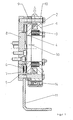
- FIG. 1 shows the brake 1, in which a solenoid coil 2 is present.
- the compression springs 3 press the armature disk 4 against the rotor 5, which is equipped with one friction lining 6 left and right (ie both sides).
- the torque (braking torque) is generated by the compression springs 3 pressing the armature disk 4 against the rotor 5 with the two friction linings 6 and a flange plate 7.
- DC is applied to the solenoid coil 2 and there is a magnetic field which attracts the armature disk 4 via the air gap 30 against the compression springs 3 to the brake 1 and thus the rotor 5 and on the circumferential teeth and the transmission flange 8 is free to rotate.
- the brake 1 is screwed over axially parallel to the central longitudinal axis extending fastening screws 10 and arranged thereon spacers 9 with the flange plate 7. In between there is a Anschraubbügel 11, which via slots 12 in an angled 90 ° thereto foot on a base plate or a base 23 (FIGS. Fig. 4 ) of the respective structure is attached.
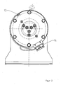
- FIG. 2 is the terminal box 14, as well as the LBAntzung 13 shown, which monitors the state of the brake (braked or released) or displays the associated control.
- FIG. 3 one sees the central transmission flange 8 with the corresponding peripheral toothing on it, which axially into the rotor 5 (FIG. FIG. 1 ) and transmits the torque.
- the bracket 11 with the slots 12 is on the base 23 (FIG. Fig. 4 ) attached.
- FIG. 4 shows the traction sheave shaft 16 driven by a conventional drive, not shown, on which the traction sheave 15 is fixed in a torsionally rigid manner by means of a feather key.
- the traction sheave shaft 16 has in the original form an additional journal 17 on which the traction sheave is additionally deposited with a conventional pillow block bearing.
- This floor storage is eliminated and it is cultivated the attachment brake with an additional storage 18 as a pendulum bearing, which thus assumes the storage of the journal 17.
- An attachment hub 19 with an additional hub 20, which is connected via a feather key, has elastic elements 21 with which the torque is transmitted to the rotor 5 of the brake.
- the attachment hub 19 is fastened by the bearing pin 17 by means of a conical clamping connection 31 and transmits the torque to the traction sheave shaft 16, which is connected to the traction sheave 15 via a feather key.
- An additional sliding bearing 22 serves for further support.
- the mounting hub 19 is connected to the intermediate flange 25 by fastening screws 29.
- the replaced press cover, which secured the traction sheave 15 axially on the cone, is replaced by a new connecting flange 26, which is connected via the elastic elements 21 and transmits the torque.
- the mounting hub 19 is mounted separately with a bearing 18 and 24 within the brake.
- FIG. 6 shows a similar variant as FIG. 5 However, here the connecting flange 26 is fastened exclusively on the inner hub 27 of the traction sheave 15 by means of screws 28.
- FIG. 7 a variant is shown in which the connecting flange 26 is attached to the outer ring of the traction sheave 15.
- FIG. 8 a variant is shown, in which from the intermediate flange 25, the elastic elements 21 projecting directly into the spokes of the traction sheave 15.
- the elastic elements 21 projecting directly into the spokes of the traction sheave 15.
- the elastic elements 21 are always 2 elastic elements 21 each left and right to a spoke fitting ( Fig. 8a ), so that a largely low-backlash torque transmission is ensured.
Landscapes
- Engineering & Computer Science (AREA)
- Mechanical Engineering (AREA)
- General Engineering & Computer Science (AREA)
- Cage And Drive Apparatuses For Elevators (AREA)
- Braking Arrangements (AREA)
- Connection Of Motors, Electrical Generators, Mechanical Devices, And The Like (AREA)
Applications Claiming Priority (2)
| Application Number | Priority Date | Filing Date | Title |
|---|---|---|---|
| DE102005022897A DE102005022897A1 (de) | 2005-05-18 | 2005-05-18 | Anbaubremse für Treibscheibe |
| PCT/EP2006/004695 WO2006122796A1 (de) | 2005-05-18 | 2006-05-17 | Anbaubremse für treibscheibe |
Publications (2)
| Publication Number | Publication Date |
|---|---|
| EP1922281A1 EP1922281A1 (de) | 2008-05-21 |
| EP1922281B1 true EP1922281B1 (de) | 2011-09-14 |
Family
ID=36699080
Family Applications (1)
| Application Number | Title | Priority Date | Filing Date |
|---|---|---|---|
| EP06753694A Not-in-force EP1922281B1 (de) | 2005-05-18 | 2006-05-17 | Anbaubremse für treibscheibe |
Country Status (9)
| Country | Link |
|---|---|
| US (1) | US7866633B2 (https=) |
| EP (1) | EP1922281B1 (https=) |
| JP (1) | JP5457026B2 (https=) |
| KR (1) | KR20080015414A (https=) |
| CN (1) | CN101175686B (https=) |
| AT (1) | ATE524409T1 (https=) |
| DE (1) | DE102005022897A1 (https=) |
| ES (1) | ES2370516T3 (https=) |
| WO (1) | WO2006122796A1 (https=) |
Cited By (1)
| Publication number | Priority date | Publication date | Assignee | Title |
|---|---|---|---|---|
| US11807493B1 (en) | 2018-10-15 | 2023-11-07 | Otis Elevator Company | Retrofitted hoist machine |
Families Citing this family (18)
| Publication number | Priority date | Publication date | Assignee | Title |
|---|---|---|---|---|
| US8783421B2 (en) | 2007-09-20 | 2014-07-22 | Thyssenkrupp Aufzugswerke Gmbh | Brake device |
| BRPI0820045B1 (pt) * | 2007-11-14 | 2020-04-28 | Inventio Ag | acionamento de elevador para acionamento e para detenção de uma cabine de elevador, processo para acionamento e para detenção de uma cabine de elevador e instalação de elevador |
| FI125327B (fi) * | 2009-01-12 | 2015-08-31 | Kone Corp | Hissikorin liikkeen estävällä lukituslaitteella varustettu hissi ja hissikorin liikkeen estävä lukituslaite |
| JP5452033B2 (ja) * | 2009-02-16 | 2014-03-26 | 三菱電機ビルテクノサービス株式会社 | エレベータ非常ブレーキ装置 |
| CN101633470B (zh) * | 2009-05-22 | 2012-05-23 | 苏州新达电扶梯部件有限公司 | 自动扶梯附加制动器 |
| US8752262B2 (en) * | 2009-12-22 | 2014-06-17 | Otis Elevator Company | Supplemental elevator brake and retrofitting installation procedure |
| CN101934995A (zh) * | 2010-08-16 | 2011-01-05 | 成都瑞迪机械实业有限公司 | 多磁极双回路盘式制动器 |
| JP5579111B2 (ja) * | 2011-03-24 | 2014-08-27 | 株式会社キトー | 無励磁作動ブレーキを備えた巻上機 |
| JP2013001557A (ja) * | 2011-06-21 | 2013-01-07 | Toshiba Elevator Co Ltd | 巻上機及び巻上機改修方法 |
| US9099148B2 (en) * | 2012-03-30 | 2015-08-04 | Oracle International Corporation | Magnetic Z-directional clutch |
| WO2017212576A1 (ja) * | 2016-06-08 | 2017-12-14 | 三菱電機株式会社 | エレベータ用巻上機の軸受装置 |
| US10208817B2 (en) * | 2016-10-10 | 2019-02-19 | Cameron International Corporation | Drawworks gearbox with redundant braking on input side |
| CN108547883B (zh) * | 2018-05-25 | 2024-05-31 | 马鞍山荣马传动机械股份有限公司 | 高速传动轴 |
| NL2021721B1 (nl) * | 2018-09-27 | 2020-05-07 | Ciass Ede B V | Samenstel van een axiale koelwaaier bestemd voor bevestiging aan een motoras van een elektromotor en een bedienbaar remmechanisme |
| CN110219905B (zh) * | 2019-06-20 | 2024-01-26 | 迈格钠磁动力股份有限公司 | 一种离心触发式缓速器和提升运输装置 |
| WO2021081488A1 (en) * | 2019-10-25 | 2021-04-29 | Mcintosh Brake Systems, Llc | Brake system and method |
| CN111942989B (zh) * | 2020-08-24 | 2021-07-23 | 广厦建设集团有限责任公司 | 一种建筑施工用施工电梯安防装置 |
| CN112727679B (zh) * | 2020-12-29 | 2022-05-31 | 崇礼新天风能有限公司 | 基于摩擦制动机构的减速装置、风力发电机制动系统 |
Family Cites Families (17)
| Publication number | Priority date | Publication date | Assignee | Title |
|---|---|---|---|---|
| US4275803A (en) * | 1979-10-01 | 1981-06-30 | Harnischfeger Corporation | Load brake |
| JPS571185A (en) * | 1980-06-03 | 1982-01-06 | Mitsubishi Electric Corp | Elevator device |
| JPS5943791A (ja) * | 1982-09-03 | 1984-03-10 | 三菱電機株式会社 | エレベ−タ用巻上機 |
| JPH0530069Y2 (https=) * | 1988-03-29 | 1993-07-30 | ||
| JPH0745315B2 (ja) * | 1988-08-26 | 1995-05-17 | 三菱電機株式会社 | 巻上機 |
| JPH0412982A (ja) * | 1990-05-07 | 1992-01-17 | Mitsubishi Electric Corp | エレベータのガイドレール固定装置 |
| US5202539A (en) * | 1991-08-28 | 1993-04-13 | Inventio Ag | Emergency brake apparatus for an elevator |
| CA2084242C (en) * | 1991-12-02 | 2000-11-07 | Richard J. Ericson | Disc brake for elevator drive sheave |
| US5201821A (en) * | 1992-01-08 | 1993-04-13 | Otis Elevator Company | Disc brake elevator drive sheave |
| US5680911A (en) * | 1996-03-05 | 1997-10-28 | Wang; Chiou Nan | Elector emergency device |
| EP0796814B1 (en) * | 1996-03-22 | 2004-09-22 | Sanyo Kogyo Co., Ltd. | Brake for hoist gear |
| DE19614267A1 (de) * | 1996-04-11 | 1997-10-16 | Atec Weiss Gmbh & Co Kg | Elastische, axial- und winkelbewegliche Kupplung |
| JP3748947B2 (ja) * | 1996-06-26 | 2006-02-22 | 株式会社産機 | 複式制動装置 |
| CN1063726C (zh) * | 1996-07-09 | 2001-03-28 | 王秋楠 | 电梯安全脱困装置 |
| JP2000230567A (ja) * | 1999-02-09 | 2000-08-22 | Koyo Seiko Co Ltd | 軸用クランプ継手 |
| JP2000344449A (ja) * | 1999-06-02 | 2000-12-12 | Teijin Seiki Co Ltd | エレベータ用駆動装置 |
| JP2003104666A (ja) * | 2001-09-28 | 2003-04-09 | Meidensha Corp | 巻上機及びエレベータ装置 |
-
2005
- 2005-05-18 DE DE102005022897A patent/DE102005022897A1/de not_active Withdrawn
-
2006
- 2006-05-17 EP EP06753694A patent/EP1922281B1/de not_active Not-in-force
- 2006-05-17 KR KR1020077027521A patent/KR20080015414A/ko not_active Withdrawn
- 2006-05-17 US US11/920,484 patent/US7866633B2/en not_active Expired - Fee Related
- 2006-05-17 WO PCT/EP2006/004695 patent/WO2006122796A1/de not_active Ceased
- 2006-05-17 ES ES06753694T patent/ES2370516T3/es active Active
- 2006-05-17 JP JP2008511634A patent/JP5457026B2/ja not_active Expired - Fee Related
- 2006-05-17 AT AT06753694T patent/ATE524409T1/de active
- 2006-05-17 CN CN2006800168260A patent/CN101175686B/zh not_active Expired - Fee Related
Cited By (1)
| Publication number | Priority date | Publication date | Assignee | Title |
|---|---|---|---|---|
| US11807493B1 (en) | 2018-10-15 | 2023-11-07 | Otis Elevator Company | Retrofitted hoist machine |
Also Published As
| Publication number | Publication date |
|---|---|
| JP2008540297A (ja) | 2008-11-20 |
| US20090236186A1 (en) | 2009-09-24 |
| US7866633B2 (en) | 2011-01-11 |
| WO2006122796A1 (de) | 2006-11-23 |
| CN101175686B (zh) | 2012-04-18 |
| ATE524409T1 (de) | 2011-09-15 |
| CN101175686A (zh) | 2008-05-07 |
| JP5457026B2 (ja) | 2014-04-02 |
| ES2370516T3 (es) | 2011-12-19 |
| KR20080015414A (ko) | 2008-02-19 |
| DE102005022897A1 (de) | 2006-11-23 |
| EP1922281A1 (de) | 2008-05-21 |
Similar Documents
| Publication | Publication Date | Title |
|---|---|---|
| EP1922281B1 (de) | Anbaubremse für treibscheibe | |
| US8079569B2 (en) | Cable drawworks for a drilling rig | |
| CN1044997C (zh) | 用于电梯驱动滑轮的盘式制动器 | |
| DE19532509A1 (de) | Reibungskupplung mit mechanisch betätigtem konzentrischen Ausrücker | |
| US5145035A (en) | Elevator disc brake | |
| DE102008058865A1 (de) | Handlüftung für eine Bremse | |
| EP1987998B1 (de) | Antriebsanordnung für Seilbahnen sowie Brems- und Kupplunseinheit hierfür | |
| EP1069068B1 (de) | Kompakter Antrieb für einen Aufzug | |
| DE102008026247B4 (de) | Kombinierte Kupplungs- Bremseinheit mit doppelt wirkender Haltebremse | |
| DE102014215911A1 (de) | Scheibenbremsanordnung | |
| EP0729913B1 (de) | Kettenzug mit auf beide Seiten der Kupplung wirkender Bremse | |
| EP4265556B1 (de) | Antriebsmaschine für einen aufzug | |
| WO2001028911A1 (de) | Aufzug mit einem an einem tragmittel gehaltenen fahrkorb | |
| DE3446657A1 (de) | Hilfsantrieb fuer aufzuege | |
| DE10148408C1 (de) | Sicherheitsbremse für einen Elektrokettenzug | |
| DE19927847C1 (de) | Lastsicherndes Bremskupplungssystem für kraftangetriebene Hebezeuge, insbesondere für Elektrokettenzüge | |
| EP4238921B1 (en) | Braking device for an elevator or escalator system | |
| DE20000913U1 (de) | Getriebehebewerk | |
| DE20217287U1 (de) | Riementrieb-Aufzugsmaschine mit Nothaltebremsen | |
| DE202004007282U1 (de) | Elektromagnetisch gelüftete Zweikreis-Anbaubremse mit ins Lagerschild integrierten Magnetspulen und Druckfederanordnung | |
| EP4306469B1 (de) | Aufzug mit glattrohr-aufzugsantrieb und antriebsträger mit einstückiger vollring-schale | |
| DE43414C (de) | Drehlager für Lastdruckschleuderbremsen und Reibungskupplungen | |
| CH624745A5 (en) | Clutch, in particular for small electric hoists | |
| DE102006040116A1 (de) | Treibscheibe mit Primärbremsanlage | |
| DE202004005300U1 (de) | Aufzugsantriebseinheit |
Legal Events
| Date | Code | Title | Description |
|---|---|---|---|
| PUAI | Public reference made under article 153(3) epc to a published international application that has entered the european phase |
Free format text: ORIGINAL CODE: 0009012 |
|
| 17P | Request for examination filed |
Effective date: 20071218 |
|
| AK | Designated contracting states |
Kind code of ref document: A1 Designated state(s): AT BE BG CH CY CZ DE DK EE ES FI FR GB GR HU IE IS IT LI LT LU LV MC NL PL PT RO SE SI SK TR |
|
| DAX | Request for extension of the european patent (deleted) | ||
| GRAP | Despatch of communication of intention to grant a patent |
Free format text: ORIGINAL CODE: EPIDOSNIGR1 |
|
| GRAS | Grant fee paid |
Free format text: ORIGINAL CODE: EPIDOSNIGR3 |
|
| GRAA | (expected) grant |
Free format text: ORIGINAL CODE: 0009210 |
|
| AK | Designated contracting states |
Kind code of ref document: B1 Designated state(s): AT BE BG CH CY CZ DE DK EE ES FI FR GB GR HU IE IS IT LI LT LU LV MC NL PL PT RO SE SI SK TR |
|
| REG | Reference to a national code |
Ref country code: GB Ref legal event code: FG4D Free format text: NOT ENGLISH |
|
| REG | Reference to a national code |
Ref country code: CH Ref legal event code: EP |
|
| REG | Reference to a national code |
Ref country code: IE Ref legal event code: FG4D Free format text: LANGUAGE OF EP DOCUMENT: GERMAN |
|
| REG | Reference to a national code |
Ref country code: DE Ref legal event code: R096 Ref document number: 502006010178 Country of ref document: DE Effective date: 20111117 |
|
| REG | Reference to a national code |
Ref country code: ES Ref legal event code: FG2A Ref document number: 2370516 Country of ref document: ES Kind code of ref document: T3 Effective date: 20111219 |
|
| REG | Reference to a national code |
Ref country code: NL Ref legal event code: VDEP Effective date: 20110914 |
|
| PG25 | Lapsed in a contracting state [announced via postgrant information from national office to epo] |
Ref country code: SE Free format text: LAPSE BECAUSE OF FAILURE TO SUBMIT A TRANSLATION OF THE DESCRIPTION OR TO PAY THE FEE WITHIN THE PRESCRIBED TIME-LIMIT Effective date: 20110914 Ref country code: FI Free format text: LAPSE BECAUSE OF FAILURE TO SUBMIT A TRANSLATION OF THE DESCRIPTION OR TO PAY THE FEE WITHIN THE PRESCRIBED TIME-LIMIT Effective date: 20110914 Ref country code: LT Free format text: LAPSE BECAUSE OF FAILURE TO SUBMIT A TRANSLATION OF THE DESCRIPTION OR TO PAY THE FEE WITHIN THE PRESCRIBED TIME-LIMIT Effective date: 20110914 |
|
| LTIE | Lt: invalidation of european patent or patent extension |
Effective date: 20110914 |
|
| PG25 | Lapsed in a contracting state [announced via postgrant information from national office to epo] |
Ref country code: LV Free format text: LAPSE BECAUSE OF FAILURE TO SUBMIT A TRANSLATION OF THE DESCRIPTION OR TO PAY THE FEE WITHIN THE PRESCRIBED TIME-LIMIT Effective date: 20110914 Ref country code: GR Free format text: LAPSE BECAUSE OF FAILURE TO SUBMIT A TRANSLATION OF THE DESCRIPTION OR TO PAY THE FEE WITHIN THE PRESCRIBED TIME-LIMIT Effective date: 20111215 Ref country code: CY Free format text: LAPSE BECAUSE OF FAILURE TO SUBMIT A TRANSLATION OF THE DESCRIPTION OR TO PAY THE FEE WITHIN THE PRESCRIBED TIME-LIMIT Effective date: 20110914 Ref country code: SI Free format text: LAPSE BECAUSE OF FAILURE TO SUBMIT A TRANSLATION OF THE DESCRIPTION OR TO PAY THE FEE WITHIN THE PRESCRIBED TIME-LIMIT Effective date: 20110914 |
|
| REG | Reference to a national code |
Ref country code: IE Ref legal event code: FD4D |
|
| PG25 | Lapsed in a contracting state [announced via postgrant information from national office to epo] |
Ref country code: SK Free format text: LAPSE BECAUSE OF FAILURE TO SUBMIT A TRANSLATION OF THE DESCRIPTION OR TO PAY THE FEE WITHIN THE PRESCRIBED TIME-LIMIT Effective date: 20110914 Ref country code: CZ Free format text: LAPSE BECAUSE OF FAILURE TO SUBMIT A TRANSLATION OF THE DESCRIPTION OR TO PAY THE FEE WITHIN THE PRESCRIBED TIME-LIMIT Effective date: 20110914 Ref country code: IE Free format text: LAPSE BECAUSE OF FAILURE TO SUBMIT A TRANSLATION OF THE DESCRIPTION OR TO PAY THE FEE WITHIN THE PRESCRIBED TIME-LIMIT Effective date: 20110914 Ref country code: IS Free format text: LAPSE BECAUSE OF FAILURE TO SUBMIT A TRANSLATION OF THE DESCRIPTION OR TO PAY THE FEE WITHIN THE PRESCRIBED TIME-LIMIT Effective date: 20120114 |
|
| PG25 | Lapsed in a contracting state [announced via postgrant information from national office to epo] |
Ref country code: NL Free format text: LAPSE BECAUSE OF FAILURE TO SUBMIT A TRANSLATION OF THE DESCRIPTION OR TO PAY THE FEE WITHIN THE PRESCRIBED TIME-LIMIT Effective date: 20110914 Ref country code: EE Free format text: LAPSE BECAUSE OF FAILURE TO SUBMIT A TRANSLATION OF THE DESCRIPTION OR TO PAY THE FEE WITHIN THE PRESCRIBED TIME-LIMIT Effective date: 20110914 Ref country code: PL Free format text: LAPSE BECAUSE OF FAILURE TO SUBMIT A TRANSLATION OF THE DESCRIPTION OR TO PAY THE FEE WITHIN THE PRESCRIBED TIME-LIMIT Effective date: 20110914 Ref country code: RO Free format text: LAPSE BECAUSE OF FAILURE TO SUBMIT A TRANSLATION OF THE DESCRIPTION OR TO PAY THE FEE WITHIN THE PRESCRIBED TIME-LIMIT Effective date: 20110914 Ref country code: PT Free format text: LAPSE BECAUSE OF FAILURE TO SUBMIT A TRANSLATION OF THE DESCRIPTION OR TO PAY THE FEE WITHIN THE PRESCRIBED TIME-LIMIT Effective date: 20120116 |
|
| PLBE | No opposition filed within time limit |
Free format text: ORIGINAL CODE: 0009261 |
|
| STAA | Information on the status of an ep patent application or granted ep patent |
Free format text: STATUS: NO OPPOSITION FILED WITHIN TIME LIMIT |
|
| PG25 | Lapsed in a contracting state [announced via postgrant information from national office to epo] |
Ref country code: DK Free format text: LAPSE BECAUSE OF FAILURE TO SUBMIT A TRANSLATION OF THE DESCRIPTION OR TO PAY THE FEE WITHIN THE PRESCRIBED TIME-LIMIT Effective date: 20110914 |
|
| 26N | No opposition filed |
Effective date: 20120615 |
|
| REG | Reference to a national code |
Ref country code: DE Ref legal event code: R097 Ref document number: 502006010178 Country of ref document: DE Effective date: 20120615 |
|
| BERE | Be: lapsed |
Owner name: CHR. MAYR G.M.B.H. & CO. KG Effective date: 20120531 |
|
| PG25 | Lapsed in a contracting state [announced via postgrant information from national office to epo] |
Ref country code: MC Free format text: LAPSE BECAUSE OF NON-PAYMENT OF DUE FEES Effective date: 20120531 |
|
| REG | Reference to a national code |
Ref country code: CH Ref legal event code: PL |
|
| GBPC | Gb: european patent ceased through non-payment of renewal fee |
Effective date: 20120517 |
|
| PG25 | Lapsed in a contracting state [announced via postgrant information from national office to epo] |
Ref country code: LI Free format text: LAPSE BECAUSE OF NON-PAYMENT OF DUE FEES Effective date: 20120531 Ref country code: CH Free format text: LAPSE BECAUSE OF NON-PAYMENT OF DUE FEES Effective date: 20120531 |
|
| PG25 | Lapsed in a contracting state [announced via postgrant information from national office to epo] |
Ref country code: BE Free format text: LAPSE BECAUSE OF NON-PAYMENT OF DUE FEES Effective date: 20120531 |
|
| PG25 | Lapsed in a contracting state [announced via postgrant information from national office to epo] |
Ref country code: GB Free format text: LAPSE BECAUSE OF NON-PAYMENT OF DUE FEES Effective date: 20120517 |
|
| PG25 | Lapsed in a contracting state [announced via postgrant information from national office to epo] |
Ref country code: BG Free format text: LAPSE BECAUSE OF FAILURE TO SUBMIT A TRANSLATION OF THE DESCRIPTION OR TO PAY THE FEE WITHIN THE PRESCRIBED TIME-LIMIT Effective date: 20111214 |
|
| REG | Reference to a national code |
Ref country code: AT Ref legal event code: MM01 Ref document number: 524409 Country of ref document: AT Kind code of ref document: T Effective date: 20120517 |
|
| PG25 | Lapsed in a contracting state [announced via postgrant information from national office to epo] |
Ref country code: AT Free format text: LAPSE BECAUSE OF NON-PAYMENT OF DUE FEES Effective date: 20120517 |
|
| REG | Reference to a national code |
Ref country code: DE Ref legal event code: R084 Ref document number: 502006010178 Country of ref document: DE |
|
| REG | Reference to a national code |
Ref country code: DE Ref legal event code: R084 Ref document number: 502006010178 Country of ref document: DE Effective date: 20140314 Ref country code: ES Ref legal event code: GC2A Effective date: 20140416 |
|
| PG25 | Lapsed in a contracting state [announced via postgrant information from national office to epo] |
Ref country code: LU Free format text: LAPSE BECAUSE OF NON-PAYMENT OF DUE FEES Effective date: 20120517 |
|
| PG25 | Lapsed in a contracting state [announced via postgrant information from national office to epo] |
Ref country code: HU Free format text: LAPSE BECAUSE OF FAILURE TO SUBMIT A TRANSLATION OF THE DESCRIPTION OR TO PAY THE FEE WITHIN THE PRESCRIBED TIME-LIMIT Effective date: 20060517 |
|
| REG | Reference to a national code |
Ref country code: FR Ref legal event code: PLFP Year of fee payment: 11 |
|
| REG | Reference to a national code |
Ref country code: FR Ref legal event code: PLFP Year of fee payment: 12 |
|
| PGFP | Annual fee paid to national office [announced via postgrant information from national office to epo] |
Ref country code: FR Payment date: 20170522 Year of fee payment: 12 Ref country code: DE Payment date: 20170529 Year of fee payment: 12 |
|
| PGFP | Annual fee paid to national office [announced via postgrant information from national office to epo] |
Ref country code: ES Payment date: 20170601 Year of fee payment: 12 |
|
| PGFP | Annual fee paid to national office [announced via postgrant information from national office to epo] |
Ref country code: TR Payment date: 20170516 Year of fee payment: 12 |
|
| PGFP | Annual fee paid to national office [announced via postgrant information from national office to epo] |
Ref country code: IT Payment date: 20170524 Year of fee payment: 12 |
|
| REG | Reference to a national code |
Ref country code: DE Ref legal event code: R119 Ref document number: 502006010178 Country of ref document: DE |
|
| PG25 | Lapsed in a contracting state [announced via postgrant information from national office to epo] |
Ref country code: FR Free format text: LAPSE BECAUSE OF NON-PAYMENT OF DUE FEES Effective date: 20180531 Ref country code: DE Free format text: LAPSE BECAUSE OF NON-PAYMENT OF DUE FEES Effective date: 20181201 Ref country code: IT Free format text: LAPSE BECAUSE OF NON-PAYMENT OF DUE FEES Effective date: 20180517 |
|
| REG | Reference to a national code |
Ref country code: ES Ref legal event code: FD2A Effective date: 20190913 |
|
| PG25 | Lapsed in a contracting state [announced via postgrant information from national office to epo] |
Ref country code: ES Free format text: LAPSE BECAUSE OF NON-PAYMENT OF DUE FEES Effective date: 20180518 |
|
| PG25 | Lapsed in a contracting state [announced via postgrant information from national office to epo] |
Ref country code: TR Free format text: LAPSE BECAUSE OF NON-PAYMENT OF DUE FEES Effective date: 20180517 |