EP1921838A2 - Lesegerät - Google Patents
Lesegerät Download PDFInfo
- Publication number
- EP1921838A2 EP1921838A2 EP07120531A EP07120531A EP1921838A2 EP 1921838 A2 EP1921838 A2 EP 1921838A2 EP 07120531 A EP07120531 A EP 07120531A EP 07120531 A EP07120531 A EP 07120531A EP 1921838 A2 EP1921838 A2 EP 1921838A2
- Authority
- EP
- European Patent Office
- Prior art keywords
- frame
- reading table
- pivotable
- camera
- reading
- Prior art date
- Legal status (The legal status is an assumption and is not a legal conclusion. Google has not performed a legal analysis and makes no representation as to the accuracy of the status listed.)
- Withdrawn
Links
Images

Classifications
-
- H—ELECTRICITY
- H04—ELECTRIC COMMUNICATION TECHNIQUE
- H04N—PICTORIAL COMMUNICATION, e.g. TELEVISION
- H04N1/00—Scanning, transmission or reproduction of documents or the like, e.g. facsimile transmission; Details thereof
- H04N1/04—Scanning arrangements, i.e. arrangements for the displacement of active reading or reproducing elements relative to the original or reproducing medium, or vice versa
- H04N1/19—Scanning arrangements, i.e. arrangements for the displacement of active reading or reproducing elements relative to the original or reproducing medium, or vice versa using multi-element arrays
- H04N1/195—Scanning arrangements, i.e. arrangements for the displacement of active reading or reproducing elements relative to the original or reproducing medium, or vice versa using multi-element arrays the array comprising a two-dimensional [2D] array
-
- H—ELECTRICITY
- H04—ELECTRIC COMMUNICATION TECHNIQUE
- H04N—PICTORIAL COMMUNICATION, e.g. TELEVISION
- H04N1/00—Scanning, transmission or reproduction of documents or the like, e.g. facsimile transmission; Details thereof
- H04N1/0035—User-machine interface; Control console
- H04N1/00405—Output means
- H04N1/00408—Display of information to the user, e.g. menus
- H04N1/0044—Display of information to the user, e.g. menus for image preview or review, e.g. to help the user position a sheet
-
- H—ELECTRICITY
- H04—ELECTRIC COMMUNICATION TECHNIQUE
- H04N—PICTORIAL COMMUNICATION, e.g. TELEVISION
- H04N1/00—Scanning, transmission or reproduction of documents or the like, e.g. facsimile transmission; Details thereof
- H04N1/04—Scanning arrangements, i.e. arrangements for the displacement of active reading or reproducing elements relative to the original or reproducing medium, or vice versa
- H04N1/19—Scanning arrangements, i.e. arrangements for the displacement of active reading or reproducing elements relative to the original or reproducing medium, or vice versa using multi-element arrays
- H04N1/195—Scanning arrangements, i.e. arrangements for the displacement of active reading or reproducing elements relative to the original or reproducing medium, or vice versa using multi-element arrays the array comprising a two-dimensional [2D] array
- H04N1/19594—Scanning arrangements, i.e. arrangements for the displacement of active reading or reproducing elements relative to the original or reproducing medium, or vice versa using multi-element arrays the array comprising a two-dimensional [2D] array using a television camera or a still video camera
-
- H—ELECTRICITY
- H04—ELECTRIC COMMUNICATION TECHNIQUE
- H04N—PICTORIAL COMMUNICATION, e.g. TELEVISION
- H04N1/00—Scanning, transmission or reproduction of documents or the like, e.g. facsimile transmission; Details thereof
- H04N1/00127—Connection or combination of a still picture apparatus with another apparatus, e.g. for storage, processing or transmission of still picture signals or of information associated with a still picture
- H04N1/00347—Connection or combination of a still picture apparatus with another apparatus, e.g. for storage, processing or transmission of still picture signals or of information associated with a still picture with another still picture apparatus, e.g. hybrid still picture apparatus
-
- H—ELECTRICITY
- H04—ELECTRIC COMMUNICATION TECHNIQUE
- H04N—PICTORIAL COMMUNICATION, e.g. TELEVISION
- H04N2201/00—Indexing scheme relating to scanning, transmission or reproduction of documents or the like, and to details thereof
- H04N2201/0077—Types of the still picture apparatus
- H04N2201/0081—Image reader
-
- H—ELECTRICITY
- H04—ELECTRIC COMMUNICATION TECHNIQUE
- H04N—PICTORIAL COMMUNICATION, e.g. TELEVISION
- H04N2201/00—Indexing scheme relating to scanning, transmission or reproduction of documents or the like, and to details thereof
- H04N2201/0077—Types of the still picture apparatus
- H04N2201/0089—Image display device
-
- H—ELECTRICITY
- H04—ELECTRIC COMMUNICATION TECHNIQUE
- H04N—PICTORIAL COMMUNICATION, e.g. TELEVISION
- H04N2201/00—Indexing scheme relating to scanning, transmission or reproduction of documents or the like, and to details thereof
- H04N2201/04—Scanning arrangements
- H04N2201/0402—Arrangements not specific to a particular one of the scanning methods covered by groups H04N1/04 - H04N1/207
- H04N2201/043—Viewing the scanned area
-
- H—ELECTRICITY
- H04—ELECTRIC COMMUNICATION TECHNIQUE
- H04N—PICTORIAL COMMUNICATION, e.g. TELEVISION
- H04N2201/00—Indexing scheme relating to scanning, transmission or reproduction of documents or the like, and to details thereof
- H04N2201/04—Scanning arrangements
- H04N2201/0402—Arrangements not specific to a particular one of the scanning methods covered by groups H04N1/04 - H04N1/207
- H04N2201/0436—Scanning a picture-bearing surface lying face up on a support
-
- H—ELECTRICITY
- H04—ELECTRIC COMMUNICATION TECHNIQUE
- H04N—PICTORIAL COMMUNICATION, e.g. TELEVISION
- H04N2201/00—Indexing scheme relating to scanning, transmission or reproduction of documents or the like, and to details thereof
- H04N2201/04—Scanning arrangements
- H04N2201/0402—Arrangements not specific to a particular one of the scanning methods covered by groups H04N1/04 - H04N1/207
- H04N2201/045—Mounting the scanning elements in a collapsible or foldable structure, e.g. for ease of transportation
Definitions
- the invention relates to a reader for visually impaired people to enable them despite their visual impairment in the situation to capture images or text and possibly fill out forms. This is done by the image or the text is displayed in an enlarged view.
- a reading device which comprises a reading table and an image acquisition unit arranged at a distance from the reading table, wherein the image acquisition unit is movable over the reading table at a substantially constant distance.
- the image capture unit is arranged in a head part and is connected via control lines to a control unit.
- a screen is arranged, which is height-adjustable relative to the head part and can also be depth-adjustable via a telescopic guide.
- the screen can be aligned relative to the head part via a rotary joint with respect to its angular position.
- the screen can be designed as a flat screen.
- the object of the invention is to provide a reading device which is transportable and can be constructed as needed.
- a reading device comprising a reading table and an image acquisition unit arranged at a distance from the reading table and a display unit, wherein the camera can be positioned above its height above the reading table via a frame connected to the reading table and wherein the display unit is attached to the frame height adjustable is attached.
- the frame is pivotable via a hinge connection relative to the reading table and the display unit is pivotable relative to the frame via a pivoting device.
- the image capture unit is also pivotable relative to the frame.
- the pivot axes for the frame and the carrier and for the pivoting device in the plane of the frame.
- the image capture unit may include a pivotable support member pivotally connected to the frame, and the camera may be disposed on a deflectable cantilever connected to the support member.
- the carrier of the image acquisition unit is pivotable in a plane essentially perpendicular to the reading table and if the camera can be pivoted into this plane together with the carrier.
- recordings of a panel are possible, which can be displayed enlarged on the display.
- the reading device illustrated in FIG. 1 comprises a reading table 1 on which a document 2 to be read is at least partially placed.
- the reading table 1 is connected at its end facing away from the viewer with a frame 3 by means of a hinge joint, so that the reading table 1 on the frame 3 is pivotable.
- the frame 3 consists of 2 bars 4, 5 with a strut 6, which extends approximately parallel to a pivot axis 7. Between the spars 4, 5 an image acquisition unit 11 is arranged at a predetermined distance from the reading table 1, which consists of a relative to the frame 3 pivotable support member 12, arranged on the support member 12 boom 13 and the actual camera 14 with a magnifying optics.
- the camera 14 is pivotable by means of the arm 13 relative to the carrier 12 about a pivot axis 16 which is perpendicular to the pivot axis 15 of the carrier to the frame 3. As a result, the camera 14 can be positioned above the reading table 1 at a distance from the frame 3 and aligned with the reading table 1.
- the display unit comprises a flat screen 17, which is connected via a frame part 18 with the frame 3.
- the frame part 18 is pivotable about a pivot axis 19 located within the frame 3 relative to the frame 3, and the flat screen 17 is pivotable relative to the frame part 18 about a swiveling axis 20 spaced from the frame 3.
- the camera 14 When folding the reader, the camera 14 is first pivoted with its arm 13 about the axis 16 to the carrier 12 out, see arrow 21. Subsequently, the carrier 12 is rotated about the axis 15 so that the camera is between the bars 4, 5, represented by the arrow 23rd
- the flat screen is rotated in the direction of arrow 24 about the axis 20 up and back until it is in the support member 18 and the support member 18 is pivoted about the axis 19 so that the frame member 18 within the spars 4, 5 of the frame 3 to lie comes, represented by the arrow 22 '.
- the camera 14 In the unfolded position of the reader shown in Fig. 1, the camera 14 is directed to a part of the original 2 to reproduce the text there on the display 17 in a magnification.
- the orientation of the camera 14 is represented by a light fan 25.
- the reading section By moving the sheet arranged on the reading table, the reading section is changed.
- a lighting unit On the boom 13, a lighting unit may be provided for additional illumination of the template. 2
- the control of the functions of the camera 14 via an external control unit 26 which transmits via a cable connection, alternatively via a wireless connection, commands to the camera control.
- an alternative orientation of the camera 14 is directed to an area in front of the user, such as on a panel, represented by the light cone 25 '.
- the camera 14 is arranged in the carrier 12, wherein the carrier 12 has been pivoted about the axis 15 in the direction of the arrow 23 'to the rear, so further away from the user. Facing the user remains the display unit 17, whose height is adjustable by adjusting the axes 19, 20.
- the position of the frame 3 with respect to the reading table 1 has not changed, that is, the frame 3 is locked with respect to the pivot axis 7 relative to the reading table 1.
- All hinges and swivel axes can be infinitely locked or adjusted in stages.
- securing means may be provided to fix an reached position and to protect against unintentional adjustment.
- Fig. 3 the reader is shown in a folded state.
- the reading table 1 is at the bottom and the frame 3 is based on the edge of the reading table.
- the boom 13 has been brought by rotation about the arrow 23 (Fig. 1) in an upwardly pivoted position, so that the optics of the boom 13 located on the camera 14 is protected.
Landscapes
- Engineering & Computer Science (AREA)
- Multimedia (AREA)
- Signal Processing (AREA)
- Human Computer Interaction (AREA)
- Facsimile Scanning Arrangements (AREA)
- Studio Devices (AREA)
Abstract
Description
- Die Erfindung betrifft ein Lesegerät für Sehbehinderte Menschen, um diese trotz ihrer Sehbehinderung in die Lage zu versetzen, Bilder oder Text zu erfassen und gegebenenfalls Formulare auszufüllen. Dies geschieht dadurch, dass das Bild oder der Text in vergrößerter Darstellung wiedergegeben wird.
- Aus der
DE 199 52 393 A1 ist ein Lesegerät bekannt, das einen Lesetisch und eine in einem Abstand zu dem Lesetisch angeordnete Bilderfassungseinheit umfasst, wobei die Bilderfassungseinheit in einem im Wesentlichen konstanten Abstand über den Lesetisch bewegbar ist. Die Bilderfassungseinheit ist in einem Kopfteil angeordnet und ist über Steuerleitungen mit einem Steuergerät verbunden. Im Bereich des Kopfteils ist ein Bildschirm angeordnet, der gegenüber dem Kopfteil höhenverstellbar ist und über eine Teleskopführung auch tiefenverstellbar sein kann. Der Bildschirm ist gegenüber dem Kopfteil über ein Drehgelenk bezüglich seiner Winkellage ausrichtbar. Dabei kann der Bildschirm als Flachbildschirm ausgeführt sein. - Obwohl dieses Lesegerät eine große Hilfe für Sehbehinderte Menschen ist, besteht der Nachteil, dass es schwer zu transportieren ist auf Grund des starren Aufbaus.
- Die Aufgabe der Erfindung besteht darin, ein Lesegerät bereit zu stellen, welches transportabel ist und bedarfsweise aufgebaut werden kann.
- Die Aufgabe wird gelöst mit einem Lesegerät, umfassend einen Lesetisch und eine in einem Abstand zu dem Lesetisch angeordnete Bilderfassungseinheit und eine Anzeigeeinheit, wobei die Kamera über einen mit dem Lesetisch verbundenen Rahmen in ihrer Höhe über dem Lesetisch positionierbar ist und wobei die Anzeigeeinheit an dem Rahmen höhenverstellbar befestigt ist. Der Rahmen ist über eine Scharnierverbindung gegenüber dem Lesetisch verschwenkbar und die Anzeigeeinheit ist über eine Schwenkvorrichtung gegenüber dem Rahmen verschwenkbar. Die Bilderfassungseinheit ist ebenfalls gegenüber dem Rahmen schwenkbar.
- Vorteilhafterweise liegen die Schwenkachsen für den Rahmen und den Träger sowie für die Schwenkvorrichtung in der Ebene des Rahmens.
- Die Bilderfassungseinheit kann ein schwenkbares Trägerteil aufweisen, das mit dem Rahmen schwenkbar verbunden ist, und die Kamera kann an einem mit dem Trägerteil verbundenen auslenkbaren Ausleger angeordnet sein.
- Besonders vorteilhaft ist es, wenn der Träger der Bilderfassungseinheit in eine Ebene im Wesentlichen senkrecht zum Lesetisch schwenkbar ist und wenn die Kamera zusammen mit dem Träger in diese Ebene verschwenkbar ist. Hierdurch sind Aufnahmen von einer Tafel möglich, die vergrößert auf der Anzeige dargestellt werden können.
- In der Zeichnung ist ein Ausführungsbeispiel der Erfindung dargestellt. Es zeigt:
- Fig. 1
- ein erfindungsgemäßes Lesegerät in perspektivischer Ansicht, die
- Fig. 2
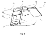
- das Lesegerät aus Fig. 1 in einer alternativen Ausrichtung der Bilderfassungseinheit.
- Fig. 3
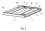
- das Lesegerät in einem zusammengefalteten Zustand.
- Das in Fig. 1 dargestellte Lesegerät umfasst einen Lesetisch 1, auf welchem eine zulesende Vorlage 2 zumindest teilweise aufgelegt ist. Der Lesetisch 1 ist an seinem vom Betrachter abgewandten Ende mit einem Rahmen 3 mittels eines Scharniergelenks verbunden, so dass der Lesetisch 1 auf den Rahmen 3 hin verschwenkbar ist.
- Der Rahmen 3 besteht aus 2 Holmen 4, 5 mit einem Verstrebungsteil 6, welches sich in etwa parallel zu einer Schwenkachse 7 erstreckt. Zwischen den Holmen 4, 5 ist in einem vorgegebenen Abstand zum Lesetisch 1 eine Bilderfassungseinheit 11 angeordnet, die aus einem gegenüber dem Rahmen 3 verschwenkbaren Trägerteil 12, einem an dem Trägerteil 12 angeordneten Ausleger 13 und der eigentlichen Kamera 14 mit einer Vergrößerungsoptik besteht. Die Kamera 14 ist mittels des Auslegers 13 gegenüber dem Träger 12 um eine Schwenkachse 16 verschwenkbar, die senkrecht auf der Schwenkachse 15 des Trägers zum Rahmen 3 steht. Dadurch kann die Kamera 14 oberhalb des Lesetisches 1 in einer Entfernung zum Rahmen 3 positioniert und zu dem Lesetisch 1 ausgerichtet werden.
- Die Anzeigeeinheit umfasst einen Flachbildschirm 17, der über ein Rahmenteil 18 mit dem Rahmen 3 verbunden ist. Das Rahmenteil 18 ist um eine innerhalb des Rahmens 3 liegende Schwenkachse 19 gegenüber dem Rahmen 3 verschwenkbar und der Flachbildschirm 17 ist um eine zum Rahmen 3 beabstandete Verschwenkachse 20 gegenüber dem Rahmenteil 18 verschwenkbar.
- Beim Zusammenklappen des Lesegeräts wird zunächst die Kamera 14 mit ihrem Ausleger 13 um die Achse 16 zum Träger 12 hin verschwenkt, siehe Pfeil 21. Anschließend wird der Träger 12 so um die Achse 15 gedreht, dass die Kamera zwischen den Holmen 4, 5 liegt, dargestellt durch den Pfeil 23.
- Der Flachbildschirm wird in Richtung des Pfeils 24 um die Achse 20 nach oben und hinten gedreht, bis er im Trägerteil 18 liegt und das Trägerteil 18 wird um die Achse 19 so geschwenkt, dass das Rahmenteil 18 innerhalb der Holme 4, 5 des Rahmens 3 zu liegen kommt, dargestellt durch den Pfeil 22'.
- Schließlich wird der Rahmen 3 um die Achse 7 auf den Lesetisch zugeschwenkt, bis dieser ebenfalls zwischen den Holmen 4, 5 zu liegen kommt, dargestellt durch den Pfeil 24.
- In der in Fig. 1 dargestellten aufgeklappten Stellung des Lesegeräts ist die Kamera 14 auf einen Teil der Vorlage 2 gerichtet, um den dort vorhandenen Text auf der Anzeige 17 in einer Vergrößerung wiederzugeben. Die Ausrichtung der Kamera 14 ist durch einen Lichtfächer 25 dargestellt. Durch Verschieben des auf dem Lesetisch angeordneten Blattes wird der Leseausschnitt verändert. An dem Ausleger 13 kann auch eine Beleuchtungseinheit vorgesehen sein zur zusätzlichen Ausleuchtung der Vorlage 2.
- Die Steuerung der Funktionen der Kamera 14 erfolgt über ein externes Steuergerät 26, welches über eine Kabelverbindung, alternativ auch über eine kabellose Verbindung, Befehle an die Kamerasteuerung übermittelt.
- Als Funktionen können z.B. Zoom, Falschfarbendarstellung, Kontrast- und Helligkeitseinstellungen und Markierungen bereitgestellt sein.
- In Fig. 2 ist eine alternative Ausrichtung der Kamera 14 auf einen Bereich vor dem Benutzer ausgerichtet, etwa auf eine Tafel, dargestellt durch den Lichtkegel 25'. Dazu ist die Kamera 14 in dem Träger 12 angeordnet, wobei der Träger 12 um die Achse 15 in Richtung des Pfeils 23' nach hinten, also weiter vom Benutzer weg, verschwenkt wurde. Dem Benutzer zugewandt bleibt die Anzeigeeinheit 17, deren Höhe durch Verstellen um die Achsen 19, 20 einstellbar ist. Die Position des Rahmens 3 bezüglich des Lesetisches 1 hat sich nicht geändert, das heißt, der Rahmen 3 ist bezüglich der Schwenkachse 7 gegenüber dem Lesetisch 1 arretiert.
- In dieser Ansicht von schräg hinten und unten wird die Verstrebung 6 und die Konstruktion des Rahmenteils 18 mit einer zusätzlichen Verstrebung 26 und einer Versteifung im Drehgelenk um die Achse 19 in Form einer Strebe 27 deutlich.
- Sämtliche Scharniere und Schwenkachsen können stufenlos arretierbar oder in Stufen verstellt werden. Darüber hinaus können Sicherungsmittel vorgesehen sein, um eine erreichte Position zu fixieren und gegen unbeabsichtigtes Verstellen abzusichern.
- In Fig. 3 ist das Lesegerät in einem zusammengefalteten Zustand gezeigt. Der Lesetisch 1 befindet sich zu unterst und der Rahmen 3 stützt sich auf den Rand des Lesetisches ab.
- Der Ausleger 13 wurde durch Drehung um den Pfeil 23 (Fig. 1) in eine nach oben verschwenkte Position gebracht, so dass die Optik der am Ausleger 13 befindlichen Kamera 14 geschützt ist.
- Zu erkennen sind die Verstrebungen 6 des Rahmens 3, die Versteifung 26 des die Anzeigeeinheit 17 tragenden Rahmenteils 18 sowie das zweigeteilte Scharnier 28, 29 zur Arretierung des Rahmens gegenüber dem Lesetisch 1.
- Insgesamt wird im zusammengefalteten Zustand eine flache kompakte Anordnung erreicht, dank derer ein Transport in einer Aktentasche möglich ist.
Claims (5)
- Lesegerät, umfassend einen Lesetisch (1) und eine in einem Abstand zu dem Lesetisch (1) angeordnete Bilderfassungseinheit (11) und eine Anzeigeeinheit (17), wobei die Bilderfassungseinheit (11) über ein mit dem Lesetisch (1) verbundenen Rahmen (3) in ihrer Höhe über dem Lesetisch (1) positionierbar ist und wobei an dem Rahmen (3) die Anzeigeeinheit (17) höhenverstellbar befestigt ist, dadurch gekennzeichnet, dass der Rahmen (3) über ein Scharnierverbindung (28, 29) gegenüber dem Lesetisch (1) verschwenkbar ist, dass die Anzeigeeinheit (17) über eine Schwenkvorrichtung (18, 27) gegenüber dem Rahmen (3) verschwenkbar ist und dass die Bilderfassungseinheit (11) ebenfalls gegenüber dem Rahmen (3) schwenkbar ist.
- Lesegerät nach Anspruch 1, dadurch gekennzeichnet, dass die Schwenkachsen (7, 15, 19) in der Ebene des Rahmens (3) liegen.
- Lesegerät nach Anspruch 1 oder 2, dadurch gekennzeichnet, dass die Bilderfassungseinheit (11) ein schwenkbares Trägerteil (12) aufweist, das mit dem Rahmen (3) schwenkbar verbunden ist, und dass eine Kamera (14) an einem mit dem Trägerteil (12) verbundenen auslenkbaren Ausleger (13) angeordnet ist.
- Lesegerät nach einem der Ansprüche 1 bis 3, dadurch gekennzeichnet, dass der Bildausschnitt (25) der Kamera (14) motorisch verstellbar ist, insbesondere über externe Eingabemittel (26).
- Lesegerät nach einem der Ansprüche 1 bis 4, dadurch gekennzeichnet, dass der Träger (12) der Bilderfassungseinheit (11) in eine Ebene im wesentlichen senkrecht zum Lesetisch (1) schwenkbar ist und dass die Kamera (14) zusammen mit dem Träger (12) in diese Ebene verschwenkbar ist.
Applications Claiming Priority (1)
| Application Number | Priority Date | Filing Date | Title |
|---|---|---|---|
| DE200610053652 DE102006053652A1 (de) | 2006-11-13 | 2006-11-13 | Lesegerät |
Publications (2)
| Publication Number | Publication Date |
|---|---|
| EP1921838A2 true EP1921838A2 (de) | 2008-05-14 |
| EP1921838A3 EP1921838A3 (de) | 2009-01-28 |
Family
ID=39110868
Family Applications (1)
| Application Number | Title | Priority Date | Filing Date |
|---|---|---|---|
| EP07120531A Withdrawn EP1921838A3 (de) | 2006-11-13 | 2007-11-13 | Lesegerät |
Country Status (2)
| Country | Link |
|---|---|
| EP (1) | EP1921838A3 (de) |
| DE (1) | DE102006053652A1 (de) |
Cited By (11)
| Publication number | Priority date | Publication date | Assignee | Title |
|---|---|---|---|---|
| EP2321960A4 (de) * | 2008-08-04 | 2012-05-30 | Freedom Scientific Inc | Tragbare kamera mit multipositionslupe |
| US8264598B2 (en) | 2008-09-22 | 2012-09-11 | Freedom Scientific, Inc. | Multiposition handheld electronic magnifier |
| NL2006698C2 (en) * | 2011-04-29 | 2012-10-30 | Optelec Dev B V | Portable magnifying camera. |
| DE102011075273A1 (de) | 2011-05-04 | 2012-11-08 | Baum Retec Ag | Lesegerät |
| WO2014014756A1 (en) | 2012-07-20 | 2014-01-23 | Freedom Scientific, Inc. | Multiposition magnifier camera |
| DE102012214280A1 (de) * | 2012-08-10 | 2014-02-13 | Bundesdruckerei Gmbh | Dokumentenlesegerät mit einer Dokumentenauflage |
| JP2017526286A (ja) * | 2014-08-19 | 2017-09-07 | フリーダム サイエンティフィック インコーポレイテッド | ポータブル机上用ビデオ拡大機 |
| KR102047386B1 (ko) * | 2018-11-30 | 2019-11-21 | (주) 씨앤피 | 접이식 탁상형 전자 확대기 |
| US10511749B2 (en) | 2016-02-26 | 2019-12-17 | Freedom Scientific, Inc. | Magnifier device with adjustable camera |
| GB2594597A (en) * | 2018-02-07 | 2021-11-03 | C&P Co Ltd | Foldable desk-type electronic magnifier |
| WO2021239981A1 (de) * | 2020-05-28 | 2021-12-02 | Thomas Lentfort | Portabler smartphone-scanner |
Families Citing this family (4)
| Publication number | Priority date | Publication date | Assignee | Title |
|---|---|---|---|---|
| DE102012221810A1 (de) * | 2012-11-28 | 2014-06-12 | Wolfgang Baum | Vorrichtung zum Einlesen und Ausgeben von Texten und/oder Bildern |
| DE102015209024B4 (de) * | 2015-05-18 | 2020-06-25 | LS Asset Management GmbH & Co. KG | Bildschirmlesegerät |
| DE102015209020B4 (de) * | 2015-05-18 | 2020-06-18 | LS Asset Management GmbH & Co. KG | Bildschirmlesegerät |
| DE102015209026A1 (de) * | 2015-05-18 | 2016-11-24 | Baum Retec Ag | Bildschirmlesegerät |
Family Cites Families (3)
| Publication number | Priority date | Publication date | Assignee | Title |
|---|---|---|---|---|
| US7050106B2 (en) * | 2001-11-21 | 2006-05-23 | Canon Kabushiki Kaisha | Image input device with rotatable image pickup unit |
| EP1745454A1 (de) * | 2004-04-13 | 2007-01-24 | Pulse Data International Limited | Bildvergrösserungsvorrichtung für sehbehinderte |
| US7980708B2 (en) * | 2005-06-08 | 2011-07-19 | Fujinon Corporation | Document presentation device including a movable part |
-
2006
- 2006-11-13 DE DE200610053652 patent/DE102006053652A1/de not_active Withdrawn
-
2007
- 2007-11-13 EP EP07120531A patent/EP1921838A3/de not_active Withdrawn
Cited By (26)
| Publication number | Priority date | Publication date | Assignee | Title |
|---|---|---|---|---|
| EP2321960A4 (de) * | 2008-08-04 | 2012-05-30 | Freedom Scientific Inc | Tragbare kamera mit multipositionslupe |
| US8259222B2 (en) | 2008-08-04 | 2012-09-04 | Freedom Scientific, Inc. | Portable multi position magnifier camera |
| US8804031B2 (en) | 2008-08-04 | 2014-08-12 | Freedom Scientific, Inc. | Multiposition handheld electronic magnifier |
| US9413973B2 (en) | 2008-08-04 | 2016-08-09 | Freedom Scientific, Inc. | Multiposition handheld electronic magnifier |
| US9998672B2 (en) | 2008-08-04 | 2018-06-12 | Freedom Scientific, Inc. | Multiposition handheld electronic magnifier |
| US8264598B2 (en) | 2008-09-22 | 2012-09-11 | Freedom Scientific, Inc. | Multiposition handheld electronic magnifier |
| NL2006698C2 (en) * | 2011-04-29 | 2012-10-30 | Optelec Dev B V | Portable magnifying camera. |
| DE102011075273A1 (de) | 2011-05-04 | 2012-11-08 | Baum Retec Ag | Lesegerät |
| WO2014014756A1 (en) | 2012-07-20 | 2014-01-23 | Freedom Scientific, Inc. | Multiposition magnifier camera |
| US10708546B2 (en) | 2012-07-20 | 2020-07-07 | Freedom Scientific, Inc. | Multiposition magnifier camera |
| EP2875403A4 (de) * | 2012-07-20 | 2016-03-23 | Freedom Scientific Inc | Vergrösserungskamera mit mehreren positionen |
| US9992453B2 (en) | 2012-07-20 | 2018-06-05 | Freedom Scientific, Inc. | Multiposition magnifier camera |
| US9992364B2 (en) | 2012-08-10 | 2018-06-05 | Bundesdruckerei Gmbh | Document scanning device having a document bed |
| DE102012214280A1 (de) * | 2012-08-10 | 2014-02-13 | Bundesdruckerei Gmbh | Dokumentenlesegerät mit einer Dokumentenauflage |
| JP2017526286A (ja) * | 2014-08-19 | 2017-09-07 | フリーダム サイエンティフィック インコーポレイテッド | ポータブル机上用ビデオ拡大機 |
| US10348942B2 (en) | 2014-08-19 | 2019-07-09 | Freedom Scientific, Inc. | Portable desktop video magnifier camera |
| EP3195047A4 (de) * | 2014-08-19 | 2018-04-04 | Freedom Scientific, Inc. | Tragbare desktop-videovergrösserungskamera |
| US11470226B2 (en) | 2014-08-19 | 2022-10-11 | Freedom Scientific, Inc. | Portable desktop video magnifier camera |
| US10979605B2 (en) | 2014-08-19 | 2021-04-13 | Freedom Scientific, Inc. | Portable desktop video magnifier camera |
| US11201990B2 (en) | 2016-02-26 | 2021-12-14 | Freedom Scientific, Inc. | Magnifier device with adjustable camera |
| US10511749B2 (en) | 2016-02-26 | 2019-12-17 | Freedom Scientific, Inc. | Magnifier device with adjustable camera |
| GB2594597A (en) * | 2018-02-07 | 2021-11-03 | C&P Co Ltd | Foldable desk-type electronic magnifier |
| GB2594597B (en) * | 2018-02-07 | 2022-09-21 | C&P Co Ltd | Foldable desktop electronic magnifier |
| KR102047386B1 (ko) * | 2018-11-30 | 2019-11-21 | (주) 씨앤피 | 접이식 탁상형 전자 확대기 |
| WO2020111802A1 (ko) * | 2018-11-30 | 2020-06-04 | (주) 씨앤피 | 접이식 탁상형 전자 확대기 |
| WO2021239981A1 (de) * | 2020-05-28 | 2021-12-02 | Thomas Lentfort | Portabler smartphone-scanner |
Also Published As
| Publication number | Publication date |
|---|---|
| EP1921838A3 (de) | 2009-01-28 |
| DE102006053652A1 (de) | 2008-05-15 |
Similar Documents
| Publication | Publication Date | Title |
|---|---|---|
| DE102006053652A1 (de) | Lesegerät | |
| DE202007010920U1 (de) | Präsentationssystem | |
| DE102011075273A1 (de) | Lesegerät | |
| DE102005054466B4 (de) | Vorrichtung zum Halten einer Aktivtafel | |
| WO2019120553A1 (de) | Optisches gerät | |
| DE102012012817A1 (de) | Kamerahalterung, Kamera und Stützstruktur zur Aufnahme von Kugelpanoramen | |
| DE102010014216A1 (de) | Präsentationssystem | |
| EP2899492B1 (de) | Winkelspiegelsystem | |
| DE19952393A1 (de) | Lesegerät | |
| DE202015007582U1 (de) | Klemm-Vorrichtung mit Hilfsfunktionen | |
| DE20018592U1 (de) | Anzeigeanordnung, insbesondere für ein mobiles oder stationäres Kommunikations- und/oder Datenverarbeitungsgerät | |
| DE202007013721U1 (de) | Sonnenblendenvorrichtung für Monitore | |
| DE3834315C2 (de) | ||
| DE102011052498B4 (de) | Blende zum Sicht- und Blendschutz für elektronische Displays | |
| DE4423586C2 (de) | Einbein-Stativ | |
| DE10053790A1 (de) | Anzeigeanordnung, insbesondere für ein mobiles oder stationäres Kommunikations- und/oder Datenverarbeitungsgerät | |
| WO2010094269A2 (de) | Bildschirm-betrachtungsvorrichtung für ein bildschirmgerät | |
| DE102007013565A1 (de) | Mobiler Personal Computer | |
| DE102009043835B3 (de) | Tragbarer Computer | |
| DE202008001314U1 (de) | Monitor-Blendschutz für Digitalkameras | |
| DE202013000839U1 (de) | Elektronische Lupe | |
| DE102004013685A1 (de) | Computer mit einem Blendschutz | |
| DE102007022731B4 (de) | Notebook-Monitorsonnenblendenvorrichtung | |
| DE102017122776B4 (de) | Betrachtungsvorrichtung, mit welcher sich ein Benutzer aus wählbaren Perspektiven betrachten kann | |
| DE19835432C2 (de) | Tragbares Computersystem mit einem zur kombinierten Anwendung geeigneten Bildschirm |
Legal Events
| Date | Code | Title | Description |
|---|---|---|---|
| PUAI | Public reference made under article 153(3) epc to a published international application that has entered the european phase |
Free format text: ORIGINAL CODE: 0009012 |
|
| AK | Designated contracting states |
Kind code of ref document: A2 Designated state(s): AT BE BG CH CY CZ DE DK EE ES FI FR GB GR HU IE IS IT LI LT LU LV MC MT NL PL PT RO SE SI SK TR |
|
| AX | Request for extension of the european patent |
Extension state: AL BA HR MK RS |
|
| PUAL | Search report despatched |
Free format text: ORIGINAL CODE: 0009013 |
|
| AK | Designated contracting states |
Kind code of ref document: A3 Designated state(s): AT BE BG CH CY CZ DE DK EE ES FI FR GB GR HU IE IS IT LI LT LU LV MC MT NL PL PT RO SE SI SK TR |
|
| AX | Request for extension of the european patent |
Extension state: AL BA HR MK RS |
|
| 17P | Request for examination filed |
Effective date: 20090721 |
|
| AKX | Designation fees paid |
Designated state(s): AT BE BG CH CY CZ DE DK EE ES FI FR GB GR HU IE IS IT LI LT LU LV MC MT NL PL PT RO SE SI SK TR |
|
| 17Q | First examination report despatched |
Effective date: 20110420 |
|
| STAA | Information on the status of an ep patent application or granted ep patent |
Free format text: STATUS: THE APPLICATION IS DEEMED TO BE WITHDRAWN |
|
| 18D | Application deemed to be withdrawn |
Effective date: 20111101 |