EP1918792A1 - Timepiece including a correction mechanism for a device displaying a time quantity - Google Patents
Timepiece including a correction mechanism for a device displaying a time quantity Download PDFInfo
- Publication number
- EP1918792A1 EP1918792A1 EP06023029A EP06023029A EP1918792A1 EP 1918792 A1 EP1918792 A1 EP 1918792A1 EP 06023029 A EP06023029 A EP 06023029A EP 06023029 A EP06023029 A EP 06023029A EP 1918792 A1 EP1918792 A1 EP 1918792A1
- Authority
- EP
- European Patent Office
- Prior art keywords
- cam
- date
- wheel
- control
- timepiece according
- Prior art date
- Legal status (The legal status is an assumption and is not a legal conclusion. Google has not performed a legal analysis and makes no representation as to the accuracy of the status listed.)
- Granted
Links
- 230000007246 mechanism Effects 0.000 title claims abstract description 36
- 230000033001 locomotion Effects 0.000 claims description 16
- 239000000523 sample Substances 0.000 claims description 11
- 230000009466 transformation Effects 0.000 claims description 6
- 238000006073 displacement reaction Methods 0.000 claims description 5
- 230000002457 bidirectional effect Effects 0.000 claims description 3
- 230000000284 resting effect Effects 0.000 claims description 3
- 230000000694 effects Effects 0.000 description 11
- 230000002123 temporal effect Effects 0.000 description 6
- 230000007935 neutral effect Effects 0.000 description 3
- 210000000056 organ Anatomy 0.000 description 3
- 230000009471 action Effects 0.000 description 2
- 230000005540 biological transmission Effects 0.000 description 2
- 230000007480 spreading Effects 0.000 description 2
- 241001057674 Phoenicococcidae Species 0.000 description 1
- 230000000295 complement effect Effects 0.000 description 1
- 230000009191 jumping Effects 0.000 description 1
- 238000004519 manufacturing process Methods 0.000 description 1
- KJFBVJALEQWJBS-XUXIUFHCSA-N maribavir Chemical compound CC(C)NC1=NC2=CC(Cl)=C(Cl)C=C2N1[C@H]1O[C@@H](CO)[C@H](O)[C@@H]1O KJFBVJALEQWJBS-XUXIUFHCSA-N 0.000 description 1
- 239000000463 material Substances 0.000 description 1
- 238000000034 method Methods 0.000 description 1
- 238000012986 modification Methods 0.000 description 1
- 230000004048 modification Effects 0.000 description 1
- 238000004804 winding Methods 0.000 description 1
Images


Classifications
-
- G—PHYSICS
- G04—HOROLOGY
- G04B—MECHANICALLY-DRIVEN CLOCKS OR WATCHES; MECHANICAL PARTS OF CLOCKS OR WATCHES IN GENERAL; TIME PIECES USING THE POSITION OF THE SUN, MOON OR STARS
- G04B19/00—Indicating the time by visual means
- G04B19/24—Clocks or watches with date or week-day indicators, i.e. calendar clocks or watches; Clockwork calendars
- G04B19/243—Clocks or watches with date or week-day indicators, i.e. calendar clocks or watches; Clockwork calendars characterised by the shape of the date indicator
- G04B19/247—Clocks or watches with date or week-day indicators, i.e. calendar clocks or watches; Clockwork calendars characterised by the shape of the date indicator disc-shaped
- G04B19/25—Devices for setting the date indicators manually
-
- G—PHYSICS
- G04—HOROLOGY
- G04B—MECHANICALLY-DRIVEN CLOCKS OR WATCHES; MECHANICAL PARTS OF CLOCKS OR WATCHES IN GENERAL; TIME PIECES USING THE POSITION OF THE SUN, MOON OR STARS
- G04B19/00—Indicating the time by visual means
- G04B19/02—Back-gearing arrangements between gear train and hands
-
- G—PHYSICS
- G04—HOROLOGY
- G04B—MECHANICALLY-DRIVEN CLOCKS OR WATCHES; MECHANICAL PARTS OF CLOCKS OR WATCHES IN GENERAL; TIME PIECES USING THE POSITION OF THE SUN, MOON OR STARS
- G04B19/00—Indicating the time by visual means
- G04B19/06—Dials
- G04B19/08—Geometrical arrangement of the graduations
- G04B19/082—Geometrical arrangement of the graduations varying from the normal closed scale
-
- G—PHYSICS
- G04—HOROLOGY
- G04B—MECHANICALLY-DRIVEN CLOCKS OR WATCHES; MECHANICAL PARTS OF CLOCKS OR WATCHES IN GENERAL; TIME PIECES USING THE POSITION OF THE SUN, MOON OR STARS
- G04B27/00—Mechanical devices for setting the time indicating means
- G04B27/004—Mechanical devices for setting the time indicating means having several simultaneous functions, e.g. stopping or starting the clockwork or the hands
Definitions
- the present invention relates to a timepiece comprising a correction mechanism for a display device of a temporal magnitude. More specifically, the present invention relates to such a timepiece comprising a mechanism for the bidirectional correction of a display device of a temporal magnitude such as a date mechanism.
- the display devices of a time scale such as date mechanisms are, for a part of them, based on control arm systems which follow the profile of a cam and which, on a daily basis, actuate an organ date indicator.
- the cam has an abrupt flank marking the passage from the last day of a given month to the first day of the following month.
- This abrupt flank poses a problem when one wants to make a correction, for example of the indication of the date, in the anti-clockwise direction. Indeed, when we want to correct the indication of the date in the clockwise direction, in other words when we want to go from a given date to a higher date of a unit to the previous date, we do not encounter any difficulty.
- the control arm follows the profile of the cam and controls step forward forward of the date indicator member.
- the control arm reaches the steep side of the profile of the cam marking the passage of the last calendar of a given month to the first calendar of the following month, it falls, advancing by one step the date indicator organ. This is not the case when looking to roll back the date indicator organ. Indeed, in this case occurs a moment when the control arm is banging against the steep side of the profile of the cam and hangs. It becomes impossible to correct the indication of the date.
- the actuating mechanism comprises a control ring disposed concentrically with respect to the center of the watch. Depending on the position of engagement of a ring, the control ring can occupy two radial positions under the effect of the action of a bent lever.
- the Richemont document fails to mention that the control ring has a cam profile on its inner periphery.
- the object of the present invention is to provide a timepiece comprising a new type of correction mechanism of a display device, for example of the date, allowing the correction thereof at a time in clockwise, in other words in forward direction, and counter-clockwise, that is to say in reverse.
- the subject of the present invention is a timepiece comprising a bidirectional corrective mechanism for a display device of a temporal magnitude such as a date, the display device being actuated by a control lever carrying a rake and controlled by a cam on which the control rocker is supported by an arm, the support of the control rocker on the cam and the return back of said display device being provided by a second rocker said rocker of reminder also carrying a rake, a correction member actuated by a control rod for removing, via the return lever, the arm of the control lever of the cam on which it is normally supported.
- the present invention provides a timepiece comprising a correction mechanism that corrects in forward and reverse a display device of a time magnitude such as a date display device despite the fact that this display device is actuated by a rocker itself controlled by a cam.
- the corrector mechanism according to the invention comprises a second lever controlled by a control rod, by a disengagement member and which makes it possible to temporarily shift the control lever from the path of the cam on which this control rocker is normally in support. The user can then make a correction of the display mechanism in reverse because although the cam rotates, the control lever is not in its path and does not knock against it.
- the correction member is formed by an annular cam actuated by the control rod and on the profile of which the return lever is supported by an arm.
- the present invention proceeds from the general inventive idea of providing a timepiece comprising a correction mechanism for a display device of a temporal magnitude such as a date device which makes it possible to correct this device in the two directions, in other words in forward and reverse direction.
- a timepiece comprising a correction mechanism for a display device of a temporal magnitude such as a date device which makes it possible to correct this device in the two directions, in other words in forward and reverse direction.
- the present invention teaches that the control flip-flop of the cam path display device must be moved out of the rearward correction phase.
- a disengagement mechanism which, actuated by a control rod, allows to spread via another flip-flop called return lever the arm of the control lever of the cam on which it is normally supported.
- the present invention will be described in connection with a date display device. However, as will be apparent from the present description, the invention is not limited to such a date display device and can be applied in a similar manner to a day display device, to a device for displaying the date of day. 24-hour display and more generally to any type of display device of a magnitude related to time.
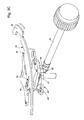
- FIG. figure 1 An exemplary embodiment of a timepiece comprising the correction mechanism according to the invention is shown in FIG. figure 1 .
- this timepiece comprises in its center a spindle switch formed by a 5a hour hand, a minute hand 5b and a second hand 5c which move over a circular dial 7.
- the spindle mechanism has already been described in the patent application European EP 1544691 on behalf of the applicant and will not be described further here.
- the display of the watch is completed by a small seconds indication 15.
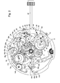
- the timepiece whose correction mechanism is shown in plan at figure 2 is a spindle watch comprising a 24-hour retrograde display corresponding to the local time of the place where the wearer of the watch usually resides and a 12-hour display corresponding to the time of the spindle of the place where the wearer of the watch is temporarily staying. It will be seen below that if the wearer of the watch wishes to correct the time of the time zone, it will also be necessary to correct the indication of the date and the indication of the day, and that if the wearer of the watch wishes to make a bet. time of the watch, it will also have to correct the retrograde display 24 hours.
- the correction mechanism of the watch includes in particular at its center a reference 1 which is integral with a wheel hours 1a.
- the reference 1 rotates in a clockwise direction and performs a complete revolution in twelve hours.
- This reference 1 meshes with a date drive wheel 2 which rotates counterclockwise at the rate of one turn in twenty-four hours.
- This driving wheel of date 2 carries a finger 4 by which it drives at a rate of one step per day a date wheel 6 which is indexed by a jumper 8 and which carries a cam 10.
- the cam has an abrupt flank 12 which marks the passage between the date of the last day of a given month and the date of the first day of the following month, in other words between the date "31" and the date "1".
- this steep sidewall 12 which, in normal times, makes it impossible to correct the date in reverse.
- the correction mechanism according to the invention is completed by a control rocker 14 provided at one of its ends with an arm 16 by which it bears against the cam 10 during normal operation, and comprising at its other end a rake 18 by which it meshes with a date display wheel 20 which carries the date indicator 9a (not visible on the figure 2 ).
- the control lever 14 is pivoted at 22 while a second rocker said return lever 24 is pivoted at 26.
- This return lever 24 has a similar structure to that of the control lever 14 including in particular a rake 28 by which it meshes with the date display wheel 20.
- the return lever 24 is constrained by a spring element 30 which tends to rotate it clockwise.
- the return lever 24 tends to rotate the date display wheel 20 in the counterclockwise direction, which tends to turn the control lever 14 clockwise and to maintain its arm 16 resting against the profile of the cam 10.
- the spring element 30 comes from material with the return lever 24 and bears against a stop 32 for its pre-arming. To achieve this result, one can achieve this latch for example by a photoengraving technique LIGA. However, it goes without saying that the spring element 30 could be made in the form of a separate part of the return lever 24.
- the return lever 24 has a feeler 34 which cooperates with a disengagement member generally designated by the general numerical reference 36.
- this member of FIG. disengagement 36 is in the form of an annular cam 38 centered on the center of the movement and on the inner profile of which the probe 34 of the return lever 24 bears.
- the feeler 34 of the return lever 24 is located at a recess 40 that presents the annular cam 38 on its profile inside. The reason for the presence of this setback 40 will be well understood on reading the following.
- the annular cam 38 has two other similar recesses for the control of two other display devices of a time magnitude as will be explained in detail later.
- the control rod 42 is kinematically connected to the annular cam 38 via an element 44 which makes it possible to convert a linear displacement of said control rod 42 into a pivoting movement of said annular cam 38.
- the element 44 the first 46 of these three tenons forms the pivot axis of the transformation element 44.
- the transformation element 44 is in the form of a rivet 46, 48 and 50 respectively. connection with the control rod 42.
- the pin 48 projects into an annular groove 52 provided at a location along the length of the control rod 42.
- the motion transformation element 44 is kinematically coupled with the annular cam 38 via the third pin 50 which is free to move in an oblong hole 54 formed in said annular cam 38.
- the correction mechanism according to the present invention is intended for a timepiece of the time zone watch type, it being understood that this example is given purely by way of illustration, the present invention being applicable to the correction of any type of display device of a temporal magnitude.
- the control rod 42 has three stable positions, namely a neutral position in which it allows the reassembly of the movement, a first drawn position which allows the correction of the indicator of 12-hour time zone (this is a jumping indicator that moves forward or backward in one-hour increments without the minute display being affected) and a second drawn position that allows the time to be set. shows.
- These three positions of the control rod 42 are conventionally indexed by a pull tab 56 of the base movement which is the link between a puller puller 60 and said control rod 42.
- control rod 42 carries with it the tenon 48, which causes the pivoting of the movement transformation element 44 around its pivot axis materialized by the pin 46.
- the pin 50 integral with the transformation element 44, slides in the oblong hole 54 and causes the pivoting of the annular cam 38 in the anti-clockwise direction.
- the annular cam 38 has rotated counterclockwise.
- the anti-clockwise pivoting of the annular cam 38 makes it possible to move the arm 16 of the control lever 14 away from the trajectory of the cam 10 as illustrated in FIG. figure 4 .
- the probe 34 of the return lever 24 rises along the side 58 of the recess 40 and slides on the inner perimeter of the annular cam 38.
- the rocker 24 rotates counterclockwise and causes, via the date display wheel 20, the pivoting of the control lever 14 also in the counterclockwise direction, which has the effect of move the arm 16 of this control lever 14 away from the path of the cam 10.
- the date indicator 9a (not visible on the figure 2 ), driven by the date display wheel 20, will move and go to the bottom of the date scale, that is to say slightly beyond the date "31".
- the present invention is not limited to a correction mechanism for a date display device. Indeed, the present invention applies very generally to any type of display of a time value such as inter alia a day display device or a 24-hour display device as is apparent from the figures 2 and 4 annexed to this patent application. It can be seen from these figures that in addition to the date display device, the Applicant has planned to equip its movement with a display device days which, for the most part, has the same structure as the date display device. More specifically, this day display mechanism comprises a driving wheel of days 2a which rotates in the counterclockwise direction being driven by the return 1.
- This driving wheel of days 2a carries a finger 4a by which it drives at a rate of one step per day a wheel of days 6a which has fourteen teeth and thus performs a complete revolution in fourteen days.
- the day wheel 6a carries a cam 10a which has a double cam profile with two steep sides 12a 1 and 12a 2 which are symmetrical with respect to the geometric center of said cam 10a. It goes without saying that such a cam profile is only a matter of choice on the part of the manufacturer and that we could very well have envisaged a cam with a simple profile performing a complete revolution in seven days. image of the cam 10 carried by the date wheel 6.
- Each of the two steep sides 12a 1 and 12a 2 of the cam 10a marks the passage of the indicator of the days of the last day of a week to the first day of the week next, from Sunday to Monday. It will be noted that the wheel of the days 6a is indexed by a jumper 8a.
- the correction mechanism of the day display device is completed by a control lever 14a which by its arm 16a bears against the profile of the cam 10a and which meshes with its rake 18a with a display wheel 20a.
- a biasing latch 24a constrained by a spring 30a and which, at one of its ends, comprises a rake 28a by which it meshes with the display wheel 20a days while at its other end, it comprises a feeler 34a which is located in a recess 40a that has the annular cam 38 on its inner profile.
- the return lever 24a pivots in the counterclockwise direction and causes, via the display wheel 20a days, pivoting of the control rocker 14a also in the counter-clockwise direction. This has the effect of spreading the arm 16a of this control rocker 14a of the path of the cam 10a. It will be understood that during this movement, the indicator of days 11a (not visible on the figure 2 ), driven by the display wheel of days 20a, will move and go to the bottom of the day scale, slightly beyond the Sunday indication.
- the watch also includes a 24 hour local time display. Therefore, when correcting the position of the hour and minute hands, you must also be able to correct the 24 hour indication.
- the 24-hour display device comprises a transmission 60 driven by the movement of the watch and which meshes with a 24 hour wheel 6b which carries a cam 10b. In one place of its profile, this cam 10b has an abrupt flank 12b which marks the passage between the twenty-fourth hour of a day and the first hour of the following day.
- a control rocker 14b is supported by its arm 16b against the profile of the cam 10b and meshes with a display wheel 24 hours 20b via its rake 18b.
- a return latch 24b constrained by a spring member 30b meshes with its rake 28b with the display wheel 24 hours 20b.
- This return lever 24b also comprises a feeler 34b, which, in the normal operating position of the watch (see FIG. figure 2 ), lies inside a recess 40b.
Landscapes
- Physics & Mathematics (AREA)
- General Physics & Mathematics (AREA)
- Geometry (AREA)
- Electromechanical Clocks (AREA)
- Electric Clocks (AREA)
Abstract
Description
La présente invention concerne une pièce d'horlogerie comprenant un mécanisme de correction pour un dispositif d'affichage d'une grandeur temporelle. Plus précisément, la présente invention concerne une telle pièce d'horlogerie comprenant un mécanisme pour la correction bidirectionnelle d'un dispositif d'affichage d'une grandeur temporelle tel qu'un mécanisme de quantième.The present invention relates to a timepiece comprising a correction mechanism for a display device of a temporal magnitude. More specifically, the present invention relates to such a timepiece comprising a mechanism for the bidirectional correction of a display device of a temporal magnitude such as a date mechanism.
Les dispositifs d'affichage d'une grandeur temporelle tels que les mécanismes de quantième sont, pour une partie d'entre eux, basés sur des systèmes de bras de commande qui suivent le profil d'une came et qui, quotidiennement, actionnent un organe indicateur de quantième. Classiquement, en un endroit de son profil, la came présente un flanc abrupt qui marque le passage du dernier jour d'un mois donné au premier jour du mois suivant. La présence, en un endroit du profil de la came, de ce flanc abrupt pose un problème lorsqu'on veut effectuer une correction, par exemple de l'indication du quantième, dans le sens anti-horaire. En effet, lorsqu'on veut corriger l'indication du quantième dans le sens horaire, autrement dit lorsqu'on veut passer d'un quantième donné à un quantième supérieur d'une unité au quantième précédent, on ne rencontre pas de difficulté. Le bras de commande suit le profil de la came et commande pas à pas l'avance en marche avant de l'organe indicateur de quantième. Lorsque le bras de commande arrive à hauteur du flanc abrupt du profil de la came marquant le passage du dernier quantième d'un mois donné au premier quantième du mois suivant, il tombe, faisant avancer d'un pas l'organe indicateur de quantième. Il n'en va pas de même lorsqu'on cherche à faire reculer l'organe indicateur de quantième. En effet, dans ce cas survient un moment où le bras de commande vient taper contre le flanc abrupt du profil de la came et se bloque. Il devient alors impossible de corriger l'indication du quantième.The display devices of a time scale such as date mechanisms are, for a part of them, based on control arm systems which follow the profile of a cam and which, on a daily basis, actuate an organ date indicator. Conventionally, at one point of its profile, the cam has an abrupt flank marking the passage from the last day of a given month to the first day of the following month. The presence, in one place of the profile of the cam, of this abrupt flank poses a problem when one wants to make a correction, for example of the indication of the date, in the anti-clockwise direction. Indeed, when we want to correct the indication of the date in the clockwise direction, in other words when we want to go from a given date to a higher date of a unit to the previous date, we do not encounter any difficulty. The control arm follows the profile of the cam and controls step forward forward of the date indicator member. When the control arm reaches the steep side of the profile of the cam marking the passage of the last calendar of a given month to the first calendar of the following month, it falls, advancing by one step the date indicator organ. This is not the case when looking to roll back the date indicator organ. Indeed, in this case occurs a moment when the control arm is banging against the steep side of the profile of the cam and hangs. It becomes impossible to correct the indication of the date.
Pour remédier à ce problème, différentes solutions ont déjà été proposées. A titre d'exemple, on connaît par le document de brevet
On connaît également par le document de brevet
On connaît aussi par le document de brevet
On connaît enfin par le document de brevet
Au vu de ce qui précède, la présente invention a pour but de procurer une pièce d'horlogerie comprenant un nouveau type de mécanisme de correction d'un dispositif d'affichage par exemple du quantième permettant la correction de celui-ci à la fois dans le sens horaire, autrement dit en marche avant, et dans le sens anti-horaire, c'est-à-dire en marche arrière.In view of the foregoing, the object of the present invention is to provide a timepiece comprising a new type of correction mechanism of a display device, for example of the date, allowing the correction thereof at a time in clockwise, in other words in forward direction, and counter-clockwise, that is to say in reverse.
A cet effet, la présente invention a pour objet une pièce d'horlogerie comprenant un mécanisme correcteur bidirectionnel pour un dispositif d'affichage d'une grandeur temporelle tel qu'un quantième, le dispositif d'affichage étant actionné par une bascule de commande portant un râteau et commandée par une came sur laquelle la bascule de commande est en appui par un bras, l'appui de la bascule de commande sur la came et le retour en arrière dudit dispositif d'affichage étant assurés par une deuxième bascule dite bascule de rappel portant également un râteau, un organe de correction actionné par une tige de commande permettant d'écarter, via la bascule de rappel, le bras de la bascule de commande de la came sur laquelle il est normalement en appui.For this purpose, the subject of the present invention is a timepiece comprising a bidirectional corrective mechanism for a display device of a temporal magnitude such as a date, the display device being actuated by a control lever carrying a rake and controlled by a cam on which the control rocker is supported by an arm, the support of the control rocker on the cam and the return back of said display device being provided by a second rocker said rocker of reminder also carrying a rake, a correction member actuated by a control rod for removing, via the return lever, the arm of the control lever of the cam on which it is normally supported.
Grâce à ces caractéristiques, la présente invention procure une pièce d'horlogerie comprenant un mécanisme de correction qui permet de corriger en marche avant comme en marche arrière un dispositif d'affichage d'une grandeur temporelle tel qu'un dispositif d'affichage de quantième et ce malgré le fait que ce dispositif d'affichage soit actionné par une bascule elle-même commandée par une came. Ce résultat remarquable est atteint grâce au fait que le mécanisme correcteur selon l'invention comprend une seconde bascule commandée, via une tige de commande, par un organe de débrayage et qui permet d'écarter momentanément la bascule de commande du trajet de la came sur laquelle cette bascule de commande est normalement en appui. L'utilisateur peut alors effectuer une correction du mécanisme d'affichage en marche arrière car bien que la came tourne, le levier de commande ne se trouve pas sur sa trajectoire et ne vient pas taper contre celle-ci.Thanks to these features, the present invention provides a timepiece comprising a correction mechanism that corrects in forward and reverse a display device of a time magnitude such as a date display device despite the fact that this display device is actuated by a rocker itself controlled by a cam. This remarkable result is achieved thanks to the fact that the corrector mechanism according to the invention comprises a second lever controlled by a control rod, by a disengagement member and which makes it possible to temporarily shift the control lever from the path of the cam on which this control rocker is normally in support. The user can then make a correction of the display mechanism in reverse because although the cam rotates, the control lever is not in its path and does not knock against it.
Selon une caractéristique complémentaire de l'invention, l'organe de correction est formé par une came annulaire actionnée par la tige de commande et sur le profil de laquelle la bascule de rappel vient en appui par un bras.According to a complementary feature of the invention, the correction member is formed by an annular cam actuated by the control rod and on the profile of which the return lever is supported by an arm.
On a donc affaire à une pièce circulaire avantageusement centrée sur le centre du mouvement de la pièce d'horlogerie. De par sa forme géométrique et sa planéité, une telle pièce est relativement aisée à fabriquer et permet en outre de commander plusieurs dispositifs d'affichage d'une grandeur temporelle prévus en différents endroits de son périmètre.We are therefore dealing with a circular part advantageously centered on the center of movement of the timepiece. Due to its geometric shape and its flatness, such a part is relatively easy to manufacture and also makes it possible to control a plurality of display devices of a temporal size provided at different locations of its perimeter.
D'autres caractéristiques et avantages de la présente invention ressortiront plus clairement de la description détaillée qui suit d'un exemple de réalisation du mécanisme de correction selon l'invention, cet exemple étant donné à titre purement illustratif et non limitatif seulement en liaison avec le dessin annexé sur lequel:
- la
figure 1 est une vue en plan du cadran de la montre comprenant le mécanisme de correction selon l'invention; - la
figure 2 est une vue en plan du mécanisme de correction selon l'invention en position de fonctionnement normal; - la
figure 3A est une vue en perspective du mécanisme de correction de lafigure 2 sur laquelle est visible l'organe de correction actionné par une tige de commande; - la
figure 3B est une vue en détail à plus grande échelle de la zone entourée d'un cercle sur lafigure 3A ; - la
figure 3C montre l'organe de correction lorsqu'il a été actionné par la tige de commande, et - la
figure 4 montre le mécanisme de correction de lafigure 2 en position débrayée dans laquelle les bras des bascules de commande sont hors du trajet des cames.
- the
figure 1 is a plan view of the dial of the watch comprising the correction mechanism according to the invention; - the
figure 2 is a plan view of the correction mechanism according to the invention in normal operating position; - the
figure 3A is a perspective view of the correction mechanism of thefigure 2 on which is visible the correction member actuated by a control rod; - the
figure 3B is a larger scale detail of the area surrounded by a circle on thefigure 3A ; - the
figure 3C shows the correction member when it has been actuated by the control rod, and - the
figure 4 shows the correction mechanism of thefigure 2 in the disengaged position in which the arms of the control flip-flops are out of the path of the cams.
La présente invention procède de l'idée générale inventive qui consiste à procurer une pièce d'horlogerie comprenant un mécanisme de correction pour un dispositif d'affichage d'une grandeur temporelle tel qu'un dispositif de quantième qui permet de corriger ce dispositif dans les deux sens, autrement dit en marche avant comme en marche arrière. Pour atteindre cet objectif, la présente invention enseigne qu'il faut écarter la bascule de commande du dispositif d'affichage du chemin de la came en phase de correction arrière. A cet effet, il est prévu un mécanisme de débrayage qui, actionné par une tige de commande, permet d'écarter via une autre bascule appelée bascule de rappel le bras de la bascule de commande de la came sur laquelle il est normalement en appui.The present invention proceeds from the general inventive idea of providing a timepiece comprising a correction mechanism for a display device of a temporal magnitude such as a date device which makes it possible to correct this device in the two directions, in other words in forward and reverse direction. To achieve this objective, the present invention teaches that the control flip-flop of the cam path display device must be moved out of the rearward correction phase. For this purpose, there is provided a disengagement mechanism which, actuated by a control rod, allows to spread via another flip-flop called return lever the arm of the control lever of the cam on which it is normally supported.
La présente invention va être décrite en liaison avec un dispositif d'affichage de quantième. Néanmoins, comme il apparaîtra à la lecture de la présente description, l'invention ne se limite pas à un tel dispositif d'affichage de quantième et peut s'appliquer de manière analogue à un dispositif d'affichage du jour, à un dispositif d'affichage 24 heures et plus généralement à tout type de dispositif d'affichage d'une grandeur liée au temps.The present invention will be described in connection with a date display device. However, as will be apparent from the present description, the invention is not limited to such a date display device and can be applied in a similar manner to a day display device, to a device for displaying the date of day. 24-hour display and more generally to any type of display device of a magnitude related to time.
Un exemple de réalisation d'une pièce d'horlogerie comprenant le mécanisme de correction selon l'invention est représentée à la
La montre 3 est complétée par:
- un affichage rétrograde de quantième formé par une
aiguille 9a qui se déplace devant unegraduation 9b en arc de cercle qui s'étend entre le "1" et le "31"; - un affichage rétrograde du jour formé par une
aiguille 11 a qui se déplace le long d'unegraduation 11 b repérée du "lundi" au "dimanche"; - un affichage rétrograde 24 heures formé par une
aiguille 13a qui se déplace le long d'unegraduation 13b en arc de cercle qui s'étend entre "1" et "24".
- a retrograde date display formed by a
needle 9a which moves in front of agraduation 9b in an arc extending between the "1" and the "31"; - a retrograde display of the day formed by a
needle 11a which moves along agraduation 11b marked "Monday" to "Sunday"; - a 24-hour retrograde display formed by a
needle 13a which moves along agraduation 13b in an arc extending between "1" and "24".
L'affichage de la montre est complété par une indication de petite seconde 15.The display of the watch is completed by a
La pièce d'horlogerie dont le mécanisme de correction est représenté en plan à la
Comme on le voit à la
Le mécanisme de correction selon l'invention est complété par une bascule de commande 14 pourvue à l'une de ses extrémités d'un bras 16 par lequel elle est en appui contre la came 10 en période de fonctionnement normal, et comprenant à son autre extrémité un râteau 18 par lequel elle engrène avec une roue d'affichage de quantième 20 qui porte l'indicateur de quantième 9a (non visible sur la
Comme on peut le voir à l'examen du dessin, dans l'exemple représenté l'élément ressort 30 vient de matière avec la bascule de rappel 24 et est en appui contre une butée 32 pour son préarmage. Pour atteindre ce résultat, on peut réaliser cette bascule par exemple par une technique de photogravure LIGA. Il va néanmoins de soi que l'élément ressort 30 pourrait être réalisé sous la forme d'une pièce séparée de la bascule de rappel 24.As can be seen from the drawing, in the example shown the
A son extrémité opposée à celle qui porte le râteau 28, la bascule de rappel 24 présente un palpeur 34 qui coopère avec un organe de débrayage désigné dans son ensemble par la référence numérique générale 36. Dans l'exemple représenté au dessin, cet organe de débrayage 36 se présente sous la forme d'une came annulaire 38 centrée sur le centre du mouvement et sur le profil intérieur de laquelle le palpeur 34 de la bascule de rappel 24 vient en appui. En observant attentivement la
On voit sur la
En effet, comme on peut le voir à la
On a déjà dit plus haut que le mécanisme de correction selon la présente invention est destiné à une pièce d'horlogerie du type montre à fuseau horaire, étant entendu que cet exemple est donné à titre purement illustratif, la présente invention pouvant s'appliquer à la correction de tout type de dispositif d'affichage d'une grandeur temporelle. Ainsi, dans le cas d'une telle montre à fuseau, la tige de commande 42 présente trois positions stables, à savoir une position neutre dans laquelle elle permet le remontage du mouvement, une première position tirée qui permet la correction de l'indicateur de fuseau horaire 12 heures (il s'agit d'un indicateur sautant qui avance ou recule par pas d'une heure sans que l'affichage des minutes en soit affecté) et une seconde position tirée qui permet la mise à l'heure de la montre. Ces trois positions de la tige de commande 42 sont classiquement indexées par une tirette 56 du mouvement de base qui fait le lien entre un sautoir de tirette 60 et ladite tige de commande 42.It has already been said above that the correction mechanism according to the present invention is intended for a timepiece of the time zone watch type, it being understood that this example is given purely by way of illustration, the present invention being applicable to the correction of any type of display device of a temporal magnitude. Thus, in the case of such a spindle watch, the
Supposons donc maintenant que l'on exerce une traction sur la tige de commande 42 pour la faire passer de sa position neutre de remontage à sa première position tirée. Dans ce cas, la tige de commande 42 entraîne avec elle le tenon 48, ce qui provoque le pivotement de l'élément de transformation de mouvement 44 autour de son axe de pivotement matérialisé par le tenon 46. A son tour, le tenon 50, solidaire de l'élément de transformation 44, coulisse dans le trou oblong 54 et provoque le pivotement de la came annulaire 38 dans le sens anti-horaire. On se retrouve alors dans la position représentée sur la
Le pivotement dans le sens anti-horaire de la came annulaire 38 permet d'écarter le bras 16 de la bascule de commande 14 de la trajectoire de la came 10 comme illustré à la
Intéressons-nous maintenant aux raisons pour lesquelles il est nécessaire d'écarter le bras 16 de la bascule de commande 14 du trajet de la came 10. En supposant que la tige de commande 42 est amenée dans sa première position tirée, cela signifie que l'on souhaite corriger l'indication de l'heure de fuseau horaire. On va donc faire tourner la tige de commande 42 en marche avant ou en marche arrière selon que l'on veut incrémenter ou décrémenter l'indication de l'heure de fuseau horaire par pas d'une heure. Or, quand on fait tourner la tige de commande 42, on fait tourner la roue des heures (non représentée) et donc aussi le renvoi 1. Si le renvoi 1 tourne dans le sens horaire, autrement dit le sens dans lequel il tourne en régime de fonctionnement normal, la came 10 tourne dans le sens horaire et le bras 16 de la bascule de commande 14 glisse sans problème le long du profil de ladite came 10. Par contre, si en phase de correction de l'indication de fuseau dans le sens anti-horaire, le renvoi 1 tourne dans le sens anti-horaire, la came 10 va tourner dans le sens horaire et le bras 16 de la bascule de commande 14 va venir taper contre le flanc abrupt 12 de ladite came 10 et se bloquer. C'est la raison pour laquelle il faut, dans ce cas, que le bras 16 de la bascule de commande 14 soit écarté du trajet de la came 10.Let us now consider the reasons why it is necessary to move the
Comme il a déjà été mentionné en préambule, la présente invention ne se limite pas à un mécanisme de correction pour un dispositif d'affichage d'un quantième. En effet, la présente invention s'applique de manière très générale à tout type d'affichage d'une grandeur temporelle tel qu'entre autres un dispositif d'affichage des jours ou un dispositif d'affichage 24 heures comme il ressort des
Le mécanisme de correction du dispositif d'affichage des jours est complété par une bascule de commande 14a qui par son bras 16a est en appui contre le profil de la came 10a et qui engrène par son râteau 18a avec une roue d'affichage des jours 20a. Il est également prévu une bascule de rappel 24a contrainte par un ressort 30a et qui, à l'une de ses extrémités, comprend un râteau 28a par lequel elle engrène avec la roue d'affichage des jours 20a tandis qu'à son autre extrémité, elle comprend un palpeur 34a qui est situé dans un décrochement 40a que présente la came annulaire 38 sur son profil intérieur.The correction mechanism of the day display device is completed by a
On rappelle que l'on s'intéresse ici à une montre à fuseau horaire. Par conséquent, dans la première position tirée de la tige de commande 42, lorsqu'on souhaite corriger l'heure de fuseau en laissant l'heure locale inchangée, il va falloir corriger simultanément l'indication du quantième et l'indication du jour. La correction de l'indication du quantième a déjà été décrite en détail ci-dessus. La correction de l'indication du jour se fait de manière identique. En effet, lorsqu'on tourne la tige de commande 42 et que cela provoque le pivotement de la came annulaire 38 dans le sens inverse des aiguilles d'une montre, le palpeur 34a de la bascule de rappel 24a remonte le long du flanc 58a du décrochement 40a et glisse sur le périmètre intérieur de la came annulaire 38. Sous l'effet du déplacement de son palpeur 34a, la bascule de rappel 24a pivote dans le sens anti-horaire et provoque, via la roue d'affichage des jours 20a, le pivotement de la bascule de commande 14a également dans le sens anti-horaire. Ceci à pour effet d'écarter le bras 16a de cette bascule de commande 14a du trajet de la came 10a. On comprendra qu'au cours de ce mouvement, l'indicateur de jours 11a (non visible sur la
On constate donc que par une action unique sur la tige de commande, on peut corriger simultanément l'heure de fuseau aussi bien dans le sens horaire que anti-horaire, l'indication du quantième et l'indication du jour ceci en prévoyant uniquement en regard des palpeurs 34, 34a des bascules de rappel 24, 24a deux décrochements 40, 40a sur le profil intérieur de la came annulaire 38. Le dispositif de correction selon la présente invention se caractérise donc par une simplicité des moyens mis en oeuvre et par une grande facilité d'utilisation.It can therefore be seen that, by a single action on the control rod, it is possible to simultaneously correct the time of spindle both in the clockwise and counterclockwise direction, the indication of the date and the indication of the day, this only providing for the
Quand on fait passer la tige de commande 42 de sa première à sa seconde position tirée pour pouvoir effectuer la mise à l'heure de la montre, cela provoque un pivotement supplémentaire de la came annulaire 38. Ce pivotement supplémentaire est cependant sans effet sur les bascules de rappel 24, 24a dans la mesure où leurs palpeurs respectifs 34, 34a ont gravi les flancs 58, 58a des décrochements 40, 40a et glissent sur le périmètre intérieur de la came annulaire 38. Les bras 16, 16a des bascules de commande 14, 14a restent donc toujours en dehors du trajet des cames 10, 10a.When the
On a déjà précisé ci-dessus que la montre comprenait également un affichage 24 heures de l'heure locale. Par conséquent, lorsqu'on corrige la position des aiguilles des heures et des minutes, il faut également pouvoir corriger l'indication 24 heures. A cet effet, le dispositif d'affichage 24 heures comprend un renvoi 60 entraîné par le mouvement de la montre et qui engrène avec une roue 24 heures 6b qui porte une came 10b. En un endroit de son profil, cette came 10b présente un flanc abrupt 12b qui marque le passage entre la vingt-quatrième heure d'une journée et la première heure de la journée suivante. Une bascule de commande 14b est en appui par son bras 16b contre le profil de la came 10b et engrène avec une roue d'affichage 24 heures 20b via son râteau 18b. De même, une bascule de rappel 24b contrainte par un élément ressort 30b engrène par son râteau 28b avec la roue d'affichage 24 heures 20b. Cette bascule de rappel 24b comprend également un palpeur 34b, qui, en position de fonctionnement normal de la montre (voir
Néanmoins, dans la première position tirée de la tige de commande 42, le fait de faire tourner cette tige 42 dans un sens ou dans l'autre pour corriger l'heure de fuseau est sans effet sur l'affichage 24 heures. En effet, dans sa première position tirée, la tige de commande 42 attaque un train d'engrenages qui n'est pas relié au dispositif d'affichage 24 heures. Par contre, dans sa seconde position tirée correspondant à la mise à l'heure de la montre, la tige de commande attaque un autre train d'engrenages qui lui est relié au dispositif d'affichage 24 heures. Par conséquent, dans la seconde position tirée de la tige de commande 42, on peut corriger sans problème le dispositif d'affichage 24 heures dans la mesure où le bras 16b de la bascule de commande 14b est déjà écarté du trajet de la came 10b lorsque ladite tige de commande 42 est amenée dans sa première position tirée.Nevertheless, in the first position drawn from the
Il va de soi que la présente invention n'est pas limitée au mode de réalisation qui vient d'être décrit et que diverses modifications et variantes simples peuvent être envisagées par l'homme du métier sans sortir du cadre de l'invention tel que défini par les revendications annexées. En particulier, on comprendra que lorsque la tige de commande est ramenée dans sa position neutre de remontage, la came annulaire revient dans sa position d'origine et les palpeurs retombent dans leurs décrochements respectifs. Sous l'effet du déplacement du palpeur, la bascule de rappel fait pivoter la roue d'affichage et la bascule de commande revient en appui contre sa came. Pendant la phase de correction, la came aura tourné et la bascule de commande viendra en appui contre celle-ci en un endroit différent de l'endroit où elle était en appui avant la correction, de sorte que la correction effectuée sera prise en compte par le dispositif d'affichage.It goes without saying that the present invention is not limited to the embodiment which has just been described and that various modifications and simple variants can be envisaged by those skilled in the art without departing from the scope of the invention as defined by the appended claims. In particular, it will be understood that when the control rod is returned to its neutral position of reassembly, the annular cam returns to its original position and feelers fall back into their respective recesses. Under the effect of the movement of the probe, the return rocker rotates the display wheel and the control rocker rests against its cam. During the correction phase, the cam will have turned and the control lever will come to bear against it in a different place from where it was in support before the correction, so that the correction made will be taken into account by the display device.
Claims (15)
Priority Applications (7)
| Application Number | Priority Date | Filing Date | Title |
|---|---|---|---|
| AT06023029T ATE465438T1 (en) | 2006-11-06 | 2006-11-06 | CLOCK COMPRISING A CORRECTION MECHANISM FOR A DEVICE FOR DISPLAYING A TIME SIZE |
| EP06023029A EP1918792B1 (en) | 2006-11-06 | 2006-11-06 | Timepiece including a correction mechanism for a device displaying a time quantity |
| DE602006013838T DE602006013838D1 (en) | 2006-11-06 | 2006-11-06 | A watch comprising a correction mechanism for a time-scale display device |
| JP2007286974A JP5177811B2 (en) | 2006-11-06 | 2007-11-05 | Timepiece having a mechanism for modifying a device that displays a time-related quantity |
| CN200710165051XA CN101178578B (en) | 2006-11-06 | 2007-11-06 | Timepiece including a mechanism for correcting a device displaying a time related quantity |
| US11/935,880 US7625116B2 (en) | 2006-11-06 | 2007-11-06 | Timepiece including a mechanism for correcting a device displaying a time related quantity |
| HK08111818.9A HK1119786A1 (en) | 2006-11-06 | 2008-10-28 | Timepiece including a mechanism for correcting a device displaying a time related quantity |
Applications Claiming Priority (1)
| Application Number | Priority Date | Filing Date | Title |
|---|---|---|---|
| EP06023029A EP1918792B1 (en) | 2006-11-06 | 2006-11-06 | Timepiece including a correction mechanism for a device displaying a time quantity |
Publications (2)
| Publication Number | Publication Date |
|---|---|
| EP1918792A1 true EP1918792A1 (en) | 2008-05-07 |
| EP1918792B1 EP1918792B1 (en) | 2010-04-21 |
Family
ID=38229168
Family Applications (1)
| Application Number | Title | Priority Date | Filing Date |
|---|---|---|---|
| EP06023029A Active EP1918792B1 (en) | 2006-11-06 | 2006-11-06 | Timepiece including a correction mechanism for a device displaying a time quantity |
Country Status (7)
| Country | Link |
|---|---|
| US (1) | US7625116B2 (en) |
| EP (1) | EP1918792B1 (en) |
| JP (1) | JP5177811B2 (en) |
| CN (1) | CN101178578B (en) |
| AT (1) | ATE465438T1 (en) |
| DE (1) | DE602006013838D1 (en) |
| HK (1) | HK1119786A1 (en) |
Cited By (11)
| Publication number | Priority date | Publication date | Assignee | Title |
|---|---|---|---|---|
| CH705600A1 (en) * | 2011-10-07 | 2013-04-15 | Richemont Int Sa | Device with image guide for watches. |
| US8750080B2 (en) | 2011-03-23 | 2014-06-10 | Pequignet S.A. | Instantaneous driving mechanism for timepiece movement |
| EP2784603A1 (en) | 2013-03-28 | 2014-10-01 | Rolex Sa | Device for displaying time information |
| EP2824521A2 (en) | 2013-07-12 | 2015-01-14 | Rolex Sa | Clockwork mechanism, clock movement and timepiece |
| EP2824517A2 (en) | 2013-07-12 | 2015-01-14 | Rolex Sa | Clockwork mechanism, clock movement and timepiece |
| CN108153135A (en) * | 2016-12-06 | 2018-06-12 | Eta瑞士钟表制造股份有限公司 | For controlling the clockwork of multiple display devices |
| EP3540522A1 (en) * | 2018-03-13 | 2019-09-18 | Harry Winston SA | Retrograde display mechanism for a timepiece |
| EP3913442A1 (en) * | 2020-05-20 | 2021-11-24 | Blancpain SA | Retrograde display mechanism for a timepiece provided with a safety device |
| EP3989011A1 (en) * | 2020-12-24 | 2022-04-27 | Blancpain SA | Retrograde display mechanism for a timepiece of the driving type provided with a lever for disengagement of the display |
| EP3430481B1 (en) * | 2016-03-15 | 2022-05-04 | G. et F. Châtelain, succursale de Chanel SARL | Watch movement comprising a retrograde display and a jump hour ring |
| CN114563941A (en) * | 2020-11-27 | 2022-05-31 | 奥米加股份有限公司 | Roller jumping type timing meter display mechanism |
Families Citing this family (21)
| Publication number | Priority date | Publication date | Assignee | Title |
|---|---|---|---|---|
| EP1936447A2 (en) * | 2006-12-20 | 2008-06-25 | Franck Müller Watchland SA | Irregular display mechanism for a timepiece |
| JP2010216988A (en) * | 2009-03-17 | 2010-09-30 | Seiko Epson Corp | Timepiece |
| JP2012013457A (en) * | 2010-06-29 | 2012-01-19 | Techno Ark Company Limited | Calendar timepiece |
| EP2410389B1 (en) * | 2010-07-21 | 2013-10-30 | Blancpain S.A. | Bi-directional date correction mechanism for a date mechanism. Date mechanism. Time piece. |
| EP2447788B1 (en) * | 2010-11-02 | 2013-08-07 | Société anonyme de la Manufacture d'Horlogerie Audemars Piguet & Cie | Calender display device and calender watch |
| JP5715453B2 (en) * | 2011-03-13 | 2015-05-07 | セイコーインスツル株式会社 | Retrograde display mechanism and watch equipped with the same |
| CH704775A2 (en) * | 2011-04-08 | 2012-10-15 | Richemont Int Sa | chronograph mechanism. |
| EP2565729B1 (en) * | 2011-08-30 | 2018-01-31 | Breitling AG | Calendar mechanism |
| EP2615506B1 (en) * | 2012-01-10 | 2014-06-25 | Montres Breguet SA | Device for rapid correction of a display system |
| JP5850767B2 (en) * | 2012-03-02 | 2016-02-03 | セイコーインスツル株式会社 | Retrograde display mechanism, movement, analog watch with retrograde display mechanism and power switching method |
| JP6091942B2 (en) * | 2012-08-01 | 2017-03-08 | セイコーインスツル株式会社 | CALENDAR MECHANISM, MOVEMENT AND CALENDAR WATCH HAVING THE MECHANISM |
| US9164482B2 (en) * | 2012-08-21 | 2015-10-20 | Rolex S.A. | Coupling lever and coupling device for a horology mechanism |
| CN103869681B (en) * | 2012-12-12 | 2016-03-02 | 天王电子(深圳)有限公司 | The upper bar handsetting mechanism of a kind of mechanical watch and mechanical watch |
| EP2950164A1 (en) * | 2014-05-28 | 2015-12-02 | Omega SA | System for optional quick correction of time information |
| CH710229A2 (en) * | 2014-10-13 | 2016-04-15 | Montres Breguet Sa | Perpetual calendar differential. |
| EP3144743B1 (en) * | 2015-09-15 | 2018-03-14 | ETA SA Manufacture Horlogère Suisse | Clock movement comprising a mechanism for correcting the date |
| CN105549374B (en) * | 2016-02-04 | 2017-11-21 | 福建上润精密仪器有限公司 | Analog-type quartz crystal watch movement when one kind is without castle wheel electronics pulling needle school |
| CH712219A2 (en) * | 2016-03-15 | 2017-09-15 | Chanel Sa Genève | Mechanism for watch movement with retrograde and jumping display. |
| JP6583944B1 (en) * | 2018-10-24 | 2019-10-02 | セイコーインスツル株式会社 | Watch movement and watch |
| WO2021162067A1 (en) * | 2020-02-13 | 2021-08-19 | 富雄 柿見 | Calendar |
| CN116999024B (en) * | 2023-05-26 | 2024-07-16 | 荣耀终端有限公司 | Physiological parameter detection method, electronic device, storage medium, and program product |
Citations (3)
| Publication number | Priority date | Publication date | Assignee | Title |
|---|---|---|---|---|
| EP0869410A1 (en) * | 1997-04-04 | 1998-10-07 | Gerald Genta S.A. | Timepiece,especially wrist-watch |
| EP1336907A2 (en) * | 2002-02-14 | 2003-08-20 | Richemont International S.A. | Actuating mechanism for time setting device of a timepiece and timepiece incorporating such a mechanism |
| EP1801671A1 (en) * | 2005-12-22 | 2007-06-27 | Montres Breguet S.A. | Calendar watch provided with blocking means |
Family Cites Families (20)
| Publication number | Priority date | Publication date | Assignee | Title |
|---|---|---|---|---|
| CH544957A (en) * | 1970-03-26 | 1974-01-15 | Mingard Marcel | Oscillating rotary indicator timepiece |
| JPS5214462Y2 (en) * | 1971-07-08 | 1977-04-01 | ||
| US3820318A (en) * | 1971-08-17 | 1974-06-28 | Schild Sa A | Day date correcting device |
| US3797226A (en) * | 1972-05-16 | 1974-03-19 | Citizen Watch Co Ltd | Timepiece fitted with a regulator controllable from outside |
| DE2855898C2 (en) * | 1978-12-23 | 1981-02-12 | Gebrueder Junghans Gmbh, 7230 Schramberg | Clock, in particular wristwatch, with date and weekday displays |
| US4291397A (en) * | 1979-10-15 | 1981-09-22 | Timex Corporation | Manual date advance mechanism for a watch |
| DE3046569A1 (en) * | 1980-12-11 | 1982-07-15 | Timex Corp., 06720 Waterbury, Conn. | DATE SWITCHING DEVICE FOR AN ANALOG CLOCK |
| CH676309B5 (en) * | 1989-03-30 | 1991-07-15 | Phare Jean D Eve Sa Le | |
| CH684920B5 (en) * | 1993-08-31 | 1995-08-15 | Ebauchesfabrik Eta Ag | Timepiece. |
| JP3140700B2 (en) * | 1996-12-26 | 2001-03-05 | セイコーインスツルメンツ株式会社 | Multifunction clock |
| IT1295123B1 (en) * | 1997-03-21 | 1999-04-30 | Luca Russi | Cam device to transform the rotary movement of the hands of a watch into an alternating movement along an arc of 120 |
| JP2004534211A (en) * | 2001-03-21 | 2004-11-11 | グラスヒュッター・ウーレンベトリープ・ゲーエムベーハー | Time display adjustment device |
| EP1336908A2 (en) * | 2002-02-14 | 2003-08-20 | Richemont International S.A. | Operational unit for time setting device of a timepiece and timepiece integrating this unit |
| JP4296019B2 (en) * | 2003-03-27 | 2009-07-15 | セイコーインスツル株式会社 | Chronograph watch with nulling structure |
| DE60321193D1 (en) | 2003-12-16 | 2008-07-03 | Eta Sa Mft Horlogere Suisse | Clock whose hour hand can jump forward or backward by one-hour increments |
| JP4626971B2 (en) * | 2004-12-15 | 2011-02-09 | セイコーインスツル株式会社 | Multifunction timepiece having a fan-shaped hand movement mechanism including a return spring and a fan-shaped hand movement train wheel apparatus |
| EP1746471B1 (en) * | 2005-07-20 | 2019-09-18 | Breitling AG | Return-to-zero device for two time counters |
| DE05405596T1 (en) * | 2005-10-21 | 2007-10-11 | Rolex Sa | Clock with a mechanism for measuring adjustable predetermined time periods |
| JP2007121098A (en) * | 2005-10-27 | 2007-05-17 | Seiko Instruments Inc | Watch equipped with fan-like form watch hand displaying mechanism |
| ATE528699T1 (en) * | 2005-11-11 | 2011-10-15 | Omega Sa | ANNUAL CALENDAR MECHANISM FOR CLOCK MOVEMENT |
-
2006
- 2006-11-06 DE DE602006013838T patent/DE602006013838D1/en active Active
- 2006-11-06 EP EP06023029A patent/EP1918792B1/en active Active
- 2006-11-06 AT AT06023029T patent/ATE465438T1/en not_active IP Right Cessation
-
2007
- 2007-11-05 JP JP2007286974A patent/JP5177811B2/en active Active
- 2007-11-06 CN CN200710165051XA patent/CN101178578B/en active Active
- 2007-11-06 US US11/935,880 patent/US7625116B2/en active Active
-
2008
- 2008-10-28 HK HK08111818.9A patent/HK1119786A1/en unknown
Patent Citations (3)
| Publication number | Priority date | Publication date | Assignee | Title |
|---|---|---|---|---|
| EP0869410A1 (en) * | 1997-04-04 | 1998-10-07 | Gerald Genta S.A. | Timepiece,especially wrist-watch |
| EP1336907A2 (en) * | 2002-02-14 | 2003-08-20 | Richemont International S.A. | Actuating mechanism for time setting device of a timepiece and timepiece incorporating such a mechanism |
| EP1801671A1 (en) * | 2005-12-22 | 2007-06-27 | Montres Breguet S.A. | Calendar watch provided with blocking means |
Cited By (19)
| Publication number | Priority date | Publication date | Assignee | Title |
|---|---|---|---|---|
| US8750080B2 (en) | 2011-03-23 | 2014-06-10 | Pequignet S.A. | Instantaneous driving mechanism for timepiece movement |
| US9665070B2 (en) | 2011-10-07 | 2017-05-30 | Richemont International Sa | Device with image guide for timepieces |
| CH705600A1 (en) * | 2011-10-07 | 2013-04-15 | Richemont Int Sa | Device with image guide for watches. |
| US8995238B2 (en) | 2013-03-28 | 2015-03-31 | Rolex S.A. | Device for displaying time information |
| EP2784603A1 (en) | 2013-03-28 | 2014-10-01 | Rolex Sa | Device for displaying time information |
| EP2824517A2 (en) | 2013-07-12 | 2015-01-14 | Rolex Sa | Clockwork mechanism, clock movement and timepiece |
| US9239570B2 (en) | 2013-07-12 | 2016-01-19 | Rolex Sa | Timepiece mechanism, timepiece movement and timepiece |
| US9285775B2 (en) | 2013-07-12 | 2016-03-15 | Rolex Sa | Timepiece mechanism for correcting a display device for displaying time information, and timepiece movement and timepiece comprising the timepiece mechanism |
| EP2824521A2 (en) | 2013-07-12 | 2015-01-14 | Rolex Sa | Clockwork mechanism, clock movement and timepiece |
| EP3430481B1 (en) * | 2016-03-15 | 2022-05-04 | G. et F. Châtelain, succursale de Chanel SARL | Watch movement comprising a retrograde display and a jump hour ring |
| CN108153135A (en) * | 2016-12-06 | 2018-06-12 | Eta瑞士钟表制造股份有限公司 | For controlling the clockwork of multiple display devices |
| CN110275423B (en) * | 2018-03-13 | 2021-03-30 | 哈里·温斯顿公司 | Timepiece display mechanism, and timepiece movement and watch including the same |
| CN110275423A (en) * | 2018-03-13 | 2019-09-24 | 哈里·温斯顿公司 | Inverse jump indication mechanism for clock and watch |
| US11320787B2 (en) | 2018-03-13 | 2022-05-03 | Harry Winston Sa | Retrograde display mechanism for horology |
| EP3540522A1 (en) * | 2018-03-13 | 2019-09-18 | Harry Winston SA | Retrograde display mechanism for a timepiece |
| EP3913442A1 (en) * | 2020-05-20 | 2021-11-24 | Blancpain SA | Retrograde display mechanism for a timepiece provided with a safety device |
| US12055895B2 (en) | 2020-05-20 | 2024-08-06 | Blancpain Sa | Retrograde timepiece display mechanism provided with a safety device |
| CN114563941A (en) * | 2020-11-27 | 2022-05-31 | 奥米加股份有限公司 | Roller jumping type timing meter display mechanism |
| EP3989011A1 (en) * | 2020-12-24 | 2022-04-27 | Blancpain SA | Retrograde display mechanism for a timepiece of the driving type provided with a lever for disengagement of the display |
Also Published As
| Publication number | Publication date |
|---|---|
| CN101178578B (en) | 2011-11-30 |
| EP1918792B1 (en) | 2010-04-21 |
| CN101178578A (en) | 2008-05-14 |
| US7625116B2 (en) | 2009-12-01 |
| DE602006013838D1 (en) | 2010-06-02 |
| ATE465438T1 (en) | 2010-05-15 |
| JP2008116460A (en) | 2008-05-22 |
| JP5177811B2 (en) | 2013-04-10 |
| US20080106979A1 (en) | 2008-05-08 |
| HK1119786A1 (en) | 2009-03-13 |
Similar Documents
| Publication | Publication Date | Title |
|---|---|---|
| EP1918792B1 (en) | Timepiece including a correction mechanism for a device displaying a time quantity | |
| EP1953611B1 (en) | Timepiece comprising a mechanism for driving a device displaying a time-related value | |
| EP2533110B1 (en) | Timepiece provided with a device for the control of functions and/or time indications | |
| EP1785783B1 (en) | Annual calendar mechanism for a clock movement | |
| EP2329325B1 (en) | Display mechanism for a timepiece used to display or not the current time | |
| EP2407833B1 (en) | Clearance compensation mechanism for clock movement | |
| EP1152303B1 (en) | Timepiece with winding mechanism and mechanism for the correction of at least two indicating organs | |
| EP3008523B1 (en) | Calendar mechanism for a clock movement | |
| WO2007115984A2 (en) | Timepiece comprising a dual time zone mechanism | |
| EP3602202B1 (en) | Device for adjusting functions of a timepiece | |
| EP1286233A1 (en) | Calendar timepiece comprising an equation-of-time device | |
| CH702803A2 (en) | Displayed information e.g. date information, correcting mechanism for watch movement, has push button pivoting base of control lever in response to predefined action of user such that arm actuates one of correction levers | |
| EP2663902B1 (en) | Timepiece | |
| EP0606576A1 (en) | Moslem calendar | |
| EP2824517A2 (en) | Clockwork mechanism, clock movement and timepiece | |
| CH699794B1 (en) | An aid in maintaining the position of a ring date indicator timepiece. | |
| CH699785A2 (en) | Travel timepiece i.e. watch, has home and local hour wheels corresponding to respective time zones, and date display mechanism including control wheel driven by local hour wheel, where date wheel is driven by control wheel | |
| EP0970407A1 (en) | Time-setting mechanism for clock movement with perpetual julian date | |
| CH691086A5 (en) | clockwork perpetual calendar. | |
| EP2455823B1 (en) | Timepiece with universal time display | |
| CH697673B1 (en) | Perpetual calendar date mechanism for watch, has ratchet cooperating with surface of correction cam to retard input of ratchet for permitting ratchet to displace date wheel when displacement amplitude is higher than present amplitude | |
| WO2023072518A1 (en) | Timepiece comprising a calendar mechanism and a mechanism for correcting the date or month | |
| EP4012505A1 (en) | Timepiece device with anti-blocking mobile | |
| CH718804B1 (en) | Perpetual or annual calendar mechanism. | |
| CH509622A (en) | Calendar timepiece |
Legal Events
| Date | Code | Title | Description |
|---|---|---|---|
| PUAI | Public reference made under article 153(3) epc to a published international application that has entered the european phase |
Free format text: ORIGINAL CODE: 0009012 |
|
| AK | Designated contracting states |
Kind code of ref document: A1 Designated state(s): AT BE BG CH CY CZ DE DK EE ES FI FR GB GR HU IE IS IT LI LT LU LV MC NL PL PT RO SE SI SK TR |
|
| AX | Request for extension of the european patent |
Extension state: AL BA HR MK RS |
|
| 17P | Request for examination filed |
Effective date: 20081107 |
|
| AKX | Designation fees paid |
Designated state(s): AT BE BG CH CY CZ DE DK EE ES FI FR GB GR HU IE IS IT LI LT LU LV MC NL PL PT RO SE SI SK TR |
|
| 17Q | First examination report despatched |
Effective date: 20081229 |
|
| GRAP | Despatch of communication of intention to grant a patent |
Free format text: ORIGINAL CODE: EPIDOSNIGR1 |
|
| GRAS | Grant fee paid |
Free format text: ORIGINAL CODE: EPIDOSNIGR3 |
|
| GRAA | (expected) grant |
Free format text: ORIGINAL CODE: 0009210 |
|
| AK | Designated contracting states |
Kind code of ref document: B1 Designated state(s): AT BE BG CH CY CZ DE DK EE ES FI FR GB GR HU IE IS IT LI LT LU LV MC NL PL PT RO SE SI SK TR |
|
| REG | Reference to a national code |
Ref country code: GB Ref legal event code: FG4D Free format text: NOT ENGLISH |
|
| REG | Reference to a national code |
Ref country code: CH Ref legal event code: EP |
|
| REG | Reference to a national code |
Ref country code: IE Ref legal event code: FG4D Free format text: LANGUAGE OF EP DOCUMENT: FRENCH |
|
| REF | Corresponds to: |
Ref document number: 602006013838 Country of ref document: DE Date of ref document: 20100602 Kind code of ref document: P |
|
| REG | Reference to a national code |
Ref country code: CH Ref legal event code: NV Representative=s name: ICB INGENIEURS CONSEILS EN BREVETS SA |
|
| REG | Reference to a national code |
Ref country code: NL Ref legal event code: VDEP Effective date: 20100421 |
|
| LTIE | Lt: invalidation of european patent or patent extension |
Effective date: 20100421 |
|
| PG25 | Lapsed in a contracting state [announced via postgrant information from national office to epo] |
Ref country code: SE Free format text: LAPSE BECAUSE OF FAILURE TO SUBMIT A TRANSLATION OF THE DESCRIPTION OR TO PAY THE FEE WITHIN THE PRESCRIBED TIME-LIMIT Effective date: 20100421 Ref country code: NL Free format text: LAPSE BECAUSE OF FAILURE TO SUBMIT A TRANSLATION OF THE DESCRIPTION OR TO PAY THE FEE WITHIN THE PRESCRIBED TIME-LIMIT Effective date: 20100421 Ref country code: ES Free format text: LAPSE BECAUSE OF FAILURE TO SUBMIT A TRANSLATION OF THE DESCRIPTION OR TO PAY THE FEE WITHIN THE PRESCRIBED TIME-LIMIT Effective date: 20100801 Ref country code: LT Free format text: LAPSE BECAUSE OF FAILURE TO SUBMIT A TRANSLATION OF THE DESCRIPTION OR TO PAY THE FEE WITHIN THE PRESCRIBED TIME-LIMIT Effective date: 20100421 |
|
| REG | Reference to a national code |
Ref country code: IE Ref legal event code: FD4D |
|
| PG25 | Lapsed in a contracting state [announced via postgrant information from national office to epo] |
Ref country code: FI Free format text: LAPSE BECAUSE OF FAILURE TO SUBMIT A TRANSLATION OF THE DESCRIPTION OR TO PAY THE FEE WITHIN THE PRESCRIBED TIME-LIMIT Effective date: 20100421 Ref country code: SI Free format text: LAPSE BECAUSE OF FAILURE TO SUBMIT A TRANSLATION OF THE DESCRIPTION OR TO PAY THE FEE WITHIN THE PRESCRIBED TIME-LIMIT Effective date: 20100421 Ref country code: LV Free format text: LAPSE BECAUSE OF FAILURE TO SUBMIT A TRANSLATION OF THE DESCRIPTION OR TO PAY THE FEE WITHIN THE PRESCRIBED TIME-LIMIT Effective date: 20100421 Ref country code: IS Free format text: LAPSE BECAUSE OF FAILURE TO SUBMIT A TRANSLATION OF THE DESCRIPTION OR TO PAY THE FEE WITHIN THE PRESCRIBED TIME-LIMIT Effective date: 20100821 Ref country code: AT Free format text: LAPSE BECAUSE OF FAILURE TO SUBMIT A TRANSLATION OF THE DESCRIPTION OR TO PAY THE FEE WITHIN THE PRESCRIBED TIME-LIMIT Effective date: 20100421 |
|
| PG25 | Lapsed in a contracting state [announced via postgrant information from national office to epo] |
Ref country code: PL Free format text: LAPSE BECAUSE OF FAILURE TO SUBMIT A TRANSLATION OF THE DESCRIPTION OR TO PAY THE FEE WITHIN THE PRESCRIBED TIME-LIMIT Effective date: 20100421 Ref country code: CY Free format text: LAPSE BECAUSE OF FAILURE TO SUBMIT A TRANSLATION OF THE DESCRIPTION OR TO PAY THE FEE WITHIN THE PRESCRIBED TIME-LIMIT Effective date: 20100526 Ref country code: GR Free format text: LAPSE BECAUSE OF FAILURE TO SUBMIT A TRANSLATION OF THE DESCRIPTION OR TO PAY THE FEE WITHIN THE PRESCRIBED TIME-LIMIT Effective date: 20100722 |
|
| PG25 | Lapsed in a contracting state [announced via postgrant information from national office to epo] |
Ref country code: EE Free format text: LAPSE BECAUSE OF FAILURE TO SUBMIT A TRANSLATION OF THE DESCRIPTION OR TO PAY THE FEE WITHIN THE PRESCRIBED TIME-LIMIT Effective date: 20100421 Ref country code: DK Free format text: LAPSE BECAUSE OF FAILURE TO SUBMIT A TRANSLATION OF THE DESCRIPTION OR TO PAY THE FEE WITHIN THE PRESCRIBED TIME-LIMIT Effective date: 20100421 Ref country code: IE Free format text: LAPSE BECAUSE OF FAILURE TO SUBMIT A TRANSLATION OF THE DESCRIPTION OR TO PAY THE FEE WITHIN THE PRESCRIBED TIME-LIMIT Effective date: 20100421 Ref country code: PT Free format text: LAPSE BECAUSE OF FAILURE TO SUBMIT A TRANSLATION OF THE DESCRIPTION OR TO PAY THE FEE WITHIN THE PRESCRIBED TIME-LIMIT Effective date: 20100823 |
|
| PLBE | No opposition filed within time limit |
Free format text: ORIGINAL CODE: 0009261 |
|
| STAA | Information on the status of an ep patent application or granted ep patent |
Free format text: STATUS: NO OPPOSITION FILED WITHIN TIME LIMIT |
|
| PG25 | Lapsed in a contracting state [announced via postgrant information from national office to epo] |
Ref country code: SK Free format text: LAPSE BECAUSE OF FAILURE TO SUBMIT A TRANSLATION OF THE DESCRIPTION OR TO PAY THE FEE WITHIN THE PRESCRIBED TIME-LIMIT Effective date: 20100421 Ref country code: CZ Free format text: LAPSE BECAUSE OF FAILURE TO SUBMIT A TRANSLATION OF THE DESCRIPTION OR TO PAY THE FEE WITHIN THE PRESCRIBED TIME-LIMIT Effective date: 20100421 Ref country code: RO Free format text: LAPSE BECAUSE OF FAILURE TO SUBMIT A TRANSLATION OF THE DESCRIPTION OR TO PAY THE FEE WITHIN THE PRESCRIBED TIME-LIMIT Effective date: 20100421 |
|
| 26N | No opposition filed |
Effective date: 20110124 |
|
| PG25 | Lapsed in a contracting state [announced via postgrant information from national office to epo] |
Ref country code: IT Free format text: LAPSE BECAUSE OF FAILURE TO SUBMIT A TRANSLATION OF THE DESCRIPTION OR TO PAY THE FEE WITHIN THE PRESCRIBED TIME-LIMIT Effective date: 20100421 |
|
| BERE | Be: lapsed |
Owner name: CIE DES MONTRES LONGINES, FRANCILLON SA Effective date: 20101130 |
|
| PG25 | Lapsed in a contracting state [announced via postgrant information from national office to epo] |
Ref country code: MC Free format text: LAPSE BECAUSE OF NON-PAYMENT OF DUE FEES Effective date: 20101130 |
|
| PG25 | Lapsed in a contracting state [announced via postgrant information from national office to epo] |
Ref country code: BE Free format text: LAPSE BECAUSE OF NON-PAYMENT OF DUE FEES Effective date: 20101130 |
|
| PG25 | Lapsed in a contracting state [announced via postgrant information from national office to epo] |
Ref country code: HU Free format text: LAPSE BECAUSE OF FAILURE TO SUBMIT A TRANSLATION OF THE DESCRIPTION OR TO PAY THE FEE WITHIN THE PRESCRIBED TIME-LIMIT Effective date: 20101022 Ref country code: BG Free format text: LAPSE BECAUSE OF FAILURE TO SUBMIT A TRANSLATION OF THE DESCRIPTION OR TO PAY THE FEE WITHIN THE PRESCRIBED TIME-LIMIT Effective date: 20100421 Ref country code: LU Free format text: LAPSE BECAUSE OF NON-PAYMENT OF DUE FEES Effective date: 20101106 |
|
| PG25 | Lapsed in a contracting state [announced via postgrant information from national office to epo] |
Ref country code: TR Free format text: LAPSE BECAUSE OF FAILURE TO SUBMIT A TRANSLATION OF THE DESCRIPTION OR TO PAY THE FEE WITHIN THE PRESCRIBED TIME-LIMIT Effective date: 20100421 |
|
| PG25 | Lapsed in a contracting state [announced via postgrant information from national office to epo] |
Ref country code: BG Free format text: LAPSE BECAUSE OF FAILURE TO SUBMIT A TRANSLATION OF THE DESCRIPTION OR TO PAY THE FEE WITHIN THE PRESCRIBED TIME-LIMIT Effective date: 20100721 |
|
| REG | Reference to a national code |
Ref country code: FR Ref legal event code: PLFP Year of fee payment: 10 |
|
| REG | Reference to a national code |
Ref country code: FR Ref legal event code: PLFP Year of fee payment: 11 |
|
| REG | Reference to a national code |
Ref country code: FR Ref legal event code: PLFP Year of fee payment: 12 |
|
| REG | Reference to a national code |
Ref country code: FR Ref legal event code: PLFP Year of fee payment: 13 |
|
| P01 | Opt-out of the competence of the unified patent court (upc) registered |
Effective date: 20230701 |
|
| PGFP | Annual fee paid to national office [announced via postgrant information from national office to epo] |
Ref country code: GB Payment date: 20231019 Year of fee payment: 18 |
|
| PGFP | Annual fee paid to national office [announced via postgrant information from national office to epo] |
Ref country code: FR Payment date: 20231019 Year of fee payment: 18 Ref country code: DE Payment date: 20231019 Year of fee payment: 18 Ref country code: CH Payment date: 20231201 Year of fee payment: 18 |