EP1918593A2 - Druckablassvorrichtung für eine Hydraulikleitung und Hydraulikleitungskonstruktion - Google Patents
Druckablassvorrichtung für eine Hydraulikleitung und Hydraulikleitungskonstruktion Download PDFInfo
- Publication number
- EP1918593A2 EP1918593A2 EP07119211A EP07119211A EP1918593A2 EP 1918593 A2 EP1918593 A2 EP 1918593A2 EP 07119211 A EP07119211 A EP 07119211A EP 07119211 A EP07119211 A EP 07119211A EP 1918593 A2 EP1918593 A2 EP 1918593A2
- Authority
- EP
- European Patent Office
- Prior art keywords
- depressurization
- valves
- pipes
- block
- hydraulic pipe
- Prior art date
- Legal status (The legal status is an assumption and is not a legal conclusion. Google has not performed a legal analysis and makes no representation as to the accuracy of the status listed.)
- Granted
Links
- 239000003086 colorant Substances 0.000 claims description 6
- 230000002452 interceptive effect Effects 0.000 claims description 3
- 238000000034 method Methods 0.000 description 9
- 230000000694 effects Effects 0.000 description 2
- 230000002093 peripheral effect Effects 0.000 description 2
- 230000008878 coupling Effects 0.000 description 1
- 238000010168 coupling process Methods 0.000 description 1
- 238000005859 coupling reaction Methods 0.000 description 1
- 238000006467 substitution reaction Methods 0.000 description 1
- 239000002699 waste material Substances 0.000 description 1
Images





Classifications
-
- F—MECHANICAL ENGINEERING; LIGHTING; HEATING; WEAPONS; BLASTING
- F15—FLUID-PRESSURE ACTUATORS; HYDRAULICS OR PNEUMATICS IN GENERAL
- F15B—SYSTEMS ACTING BY MEANS OF FLUIDS IN GENERAL; FLUID-PRESSURE ACTUATORS, e.g. SERVOMOTORS; DETAILS OF FLUID-PRESSURE SYSTEMS, NOT OTHERWISE PROVIDED FOR
- F15B20/00—Safety arrangements for fluid actuator systems; Applications of safety devices in fluid actuator systems; Emergency measures for fluid actuator systems
- F15B20/007—Overload
-
- E—FIXED CONSTRUCTIONS
- E02—HYDRAULIC ENGINEERING; FOUNDATIONS; SOIL SHIFTING
- E02F—DREDGING; SOIL-SHIFTING
- E02F9/00—Component parts of dredgers or soil-shifting machines, not restricted to one of the kinds covered by groups E02F3/00 - E02F7/00
- E02F9/20—Drives; Control devices
- E02F9/22—Hydraulic or pneumatic drives
- E02F9/2264—Arrangements or adaptations of elements for hydraulic drives
- E02F9/2267—Valves or distributors
-
- E—FIXED CONSTRUCTIONS
- E02—HYDRAULIC ENGINEERING; FOUNDATIONS; SOIL SHIFTING
- E02F—DREDGING; SOIL-SHIFTING
- E02F9/00—Component parts of dredgers or soil-shifting machines, not restricted to one of the kinds covered by groups E02F3/00 - E02F7/00
- E02F9/20—Drives; Control devices
- E02F9/22—Hydraulic or pneumatic drives
- E02F9/2264—Arrangements or adaptations of elements for hydraulic drives
- E02F9/2275—Hoses and supports therefor and protection therefor
-
- F—MECHANICAL ENGINEERING; LIGHTING; HEATING; WEAPONS; BLASTING
- F15—FLUID-PRESSURE ACTUATORS; HYDRAULICS OR PNEUMATICS IN GENERAL
- F15B—SYSTEMS ACTING BY MEANS OF FLUIDS IN GENERAL; FLUID-PRESSURE ACTUATORS, e.g. SERVOMOTORS; DETAILS OF FLUID-PRESSURE SYSTEMS, NOT OTHERWISE PROVIDED FOR
- F15B21/00—Common features of fluid actuator systems; Fluid-pressure actuator systems or details thereof, not covered by any other group of this subclass
- F15B21/005—Filling or draining of fluid systems
Definitions
- the present invention relates to a depressurization apparatus for depressurizing the inside of a hydraulic pipe provided in a working machine such as a crusher and a demolition machine, and a hydraulic pipe structure provided with the depressurization apparatus.
- a boom forming a long attachment of a demolition machine is configured so as to be dismantled into a plurality of short unit booms in consideration to dismantlement and transportation properties of a machine or the like.
- a hydraulic pipe provided in the boom is also divided into unit pipes for every unit boom and the unit pipes are connected to and/or removed from each other by joints provided in ends of the unit pipes.
- couplers closed type couplers to be attached and detached through one touch operation with little oil leakage at the time of attaching and detaching (also called as quick couplers, self seal couplings or the like, hereinafter, simply referred to as the couplers) are generally used.
- the couplers are connected to the other joints as male and female and opened by a connecting operation force.
- Patent Document 1 Japanese Patent Laid-Open No. 2001-208221 proposes a technique that a depressurization valve is provided at an end of a pipe (including a case where the depressurization valve is provided at a joint), and residual pressure is removed by operating a push button of the depressurization valve.
- Patent Document 2 Japanese Patent No. 3294550 discloses a technique that pipes are joined into a joined pipe line through a check valve and the joined pipe line is opened by an operation of one stop valve so that oil in the pipes are all removed.
- a depressurization apparatus for a hydraulic pipe comprises a depressurization block, wherein the depressurization block is provided with a plurality of main passages to which a plurality of hydraulic pipes are connected, depressurization valves for removing oil on the inside of the hydraulic pipes through the main passages by an opening operation from the exterior, and a drain passage for joining and guiding the oil removed from the depressurization valves to the exterior.
- the depressurization block is provided with the plurality of main passages to which the plurality of hydraulic pipes are connected, the depressurization valves for removing the oil from the main passages by a manual opening operation from the exterior, and the drain passage for joining and guiding the oil removed from the depressurization valves to the exterior, the oil in the plurality of pipes can be all removed. Therefore, it is possible to highly improve a work efficiency of depressurization in comparison to the case where a depressurization work is performed for every pipe including the technique of Patent Document 1.
- each of the depressurization valves is provided with an operation element for opening a drain port by a pressing operation from the exterior, and an operation body having a plurality of operation portions for performing the pressing operation to all the operation elements at the same time is provided.
- the operation body is adapted to be held to the depressurization block in an operation state that the operation portions perform the pressing operation to all the operation elements.
- the operation body is adapted to be held in the operation state, with a configuration of collecting the removed oil in an oil receiver, one worker can perform an opening (depressurizing) operation and a collecting operation of the removed oil.
- the operation portions are provided on a back surface of the operation body and the operation body is adapted to be held to the depressurization block in a reversed and non-operation state.
- the operation body is attached to the depressurization block through a hinge so as to be rotated and reversed.
- both front and back surfaces of the operation body are painted by different colors from each other.
- each of the depressurization valves is provided with an operation element for opening a drain port by an operation from the exterior, and an interlock member to be attached to the depressurization block only in a state that all the operation elements are located on closed positions is provided.
- each of the depressurization valves is provided with a knob rotated and operated between an open position where the drain port is opened and a closed position where the drain port is closed, and the interlock member is provided with protrusions not interfering with the knobs only in a state that the knobs are located on the closed positions on a back surface of a plate lying over the depressurization valves.
- a hydraulic pipe structure of the present invention is characterized in that the depressurization block of the depressurization apparatus having any of the above configurations is provided lying over a plurality of hydraulic pipes, the hydraulic pipes are connected to the main passages of the depressurization block and an opening operation is performed to depressurization valves thereby oil on the inside of the hydraulic pipes is all removed to the exterior through the main passages and a drain passage.
- the hydraulic pipe structure of the present invention is configured on the premise that the depressurization block is provided with the plurality of main passages to which the plurality of hydraulic pipes are connected, the depressurization valves for removing the oil from the main passages by a manual opening operation from the exterior, and the drain passage for joining and guiding the oil removed from the depressurization valves to the exterior, the oil in the plurality of pipes can be all removed. Therefore, it is possible to highly improve a work efficiency of depressurization in comparison to the case where a depressurization work is performed for every pipe including the technique of Patent Document 1.
- Fig. 1 shows two unit booms 1 and 2 among a number of unit booms forming a boom of a long attachment of a demolition machine, and a plurality of (five in the figure) unit hydraulic pipes 3 and 4 provided in the unit booms.
- both the unit booms 1 and 2 are connected to each other and the corresponding unit hydraulic pipes 3 and 4 are connected to each other by joints (male side joints and female side joints) 5 and 6 thereof.
- the base end side of a hydraulic pipe formed by connecting all the unit hydraulic pipes is connected to a hydraulic pump and a tank installed in a base machine (not shown), and the front end side is connected to a plurality of hydraulic actuators provided in the attachment including the boom.
- a depressurization apparatus 7 is provided lying over the unit hydraulic pipes (hereinafter, simply called as the pipes) 3 and 4.
- FIG. 2 A configuration of the depressurization apparatus 7 is shown in Fig. 2 and the following figures in detail.
- the depressurization apparatus 7 is provided with a rectangular depressurization block 8.
- the depressurization block 8 is provided with a plurality of main passages 9 to which the pipes 3 and 4 are individually connected as shown in Figs. 5 to 7, depressurization valves 10 for removing oil on the inside of the pipes through the main passages 9 by a manual opening operation from the exterior, and one drain passage 11 for joining and guiding the oil removed from the depressurization valves 10 to the exterior.
- the drain passage 11 is provided so as to pass through in the orthogonal direction to the main passages 9, that is, the longitudinal direction of the depressurization block 8. In a state that the one end side of the drain passage 11 is closed, the other end side is connected to a drain joint 12 (refer to Figs. 2 to 4).
- the drain joint 12 is connected to a drain hose 13, and drained oil is collected in an oil receiver 14.
- the drain joint 12 is connected to a drain tube 15, and the drained oil can be returned to the tank through the drain tube 15.
- a configuration of the depressurization valve 10 is shown in the above Patent Document 1 in detail.
- the depressurization valve 10 comprises, as shown in Figs. 6 and 7, a valve body 16 arranged in a center part, an operation element 17 covered and fitted from the upper side to the valve body 16 in a state that the operation element 17 can slide in the up and down direction, a cylindrical valve case 18 having a bottom and surrounding the valve body 16 and the operation element 17 from the outer periphery side, and a coil spring 19 for always biasing the operation element 17 upward.
- the valve case 18 is screwed into a valve attachment hole 20 of the depressurization block 8 and attached to the depressurization block 8.
- the communication hole 21 is formed so as to communicate to the drain passage 11 of the depressurization block 8 through a vertical hole 22 provided in a central part of the valve body 16, a horizontal hole 23 provided in an upper part of the vertical hole 22, a peripheral groove 24 provided in an inner periphery of the operation element 17, a clearance 25 formed between contact surfaces of the valve body 16 and the operation element 17 in a state that the clearance communicates to the peripheral groove, an oil chamber 26 formed between the valve body 16 and the valve case 18, and a drain port 27 provided in a hook shape in the valve case 18 communicating to the oil chamber 26.
- the clearance 25 is closed by a seal 28 as shown in Fig. 6 in a state that the operation element 17 is raised (valve opening state).
- the clearance 25 is drawn apart from the seal 28 and opened. That is, the depressurization valve 10 is in the valve opening state.
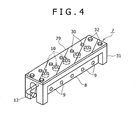
- a push plate 29 shown in Figs. 2 to 4, 6 and 7 is used as an operation body for performing the manual opening operation to the operation elements 17 from the exterior.
- protrusions 30 serving as operation portions for performing the pressing operation individually to the operation elements 17 of the depressurization valves 10 at the same interval as an interval between the operation elements 17.
- the depressurization block 8 is covered with a cover 31 for protecting the depressurization valves 10 and improving external appearance as shown in Figs. 1 to 4.
- the push plate 29 is held to an upper surface of the cover 31 by screws 32 in the operation state mentioned above as shown in Fig. 3. By this, the depressurization valves 10 are held in the valve opening state (operation state).
- the push plate 29 is, except for the time of depressurizing, screwed to the cover 31 in a reversed state that the protrusions 30 are exposed on the front side as shown in Fig. 4.
- the push plate 29 is reversed, it can be determined from the exterior that the depressurization valves 10 are in the valve opening state.
- both the front and back surfaces of the push plate 29 are painted by different colors from each other.
- diagonal lines are given to the push plate 29 in the reversed state.
- the depressurization block 8 is provided lying over the pipes 3 and 4 in both the unit booms 1 and 2, and the depressurization block 8 is provided with the main passages 9 to which the pipes 3 and 4 are connected, the depressurization valves 10 for removing the oil from the main passages 9 by the opening operation from the exterior, and the drain passage 11 for joining and guiding the oil removed to the drain ports 27 of the depressurization valves 10 to the exterior.
- the oil in the pipes 3 and 4 is all removed. Therefore, it is possible to highly improve a work efficiency of depressurization in comparison to the case where a depressurization work is performed for every pipe.
- the pipes 3 and 4 are formed so as to be opened and closed individually by the depressurization valves 10. Therefore, there are no risks such as removal of oil from all the pipes due to damage of a valve as in the technique of Patent Document 2.
- the present embodiment also has the following effects.
- the push plate 29 is screwed to the depressurization block 8 (cover 31) in the operation state and the non-operation state, while in a second embodiment, the push plate 29 is rotatably (reversibly) attached to the depressurization block 8 (cover 31) by a hinge 33.
- the point that both front and back surfaces of the push plate 29 are desirably painted by different colors from each other is the same as the first embodiment.
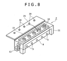
- the push plate 29 serves both as the operation body for performing the opening operation to all the depressurization valves 10 at the same time, and an interlock member for preventing the trouble that the work is started in the state that the depressurization valves 10 are opened, while in a third embodiment, each of the depressurization valves 10 is separately operated, and an interlock plate 34 serving as an exclusive member for interlock exclusively ensures only an interlock function.
- each of the depressurization valves 10 is provided with a long and thin knob 10a serving as the operation element on the upper surface side, and opened and closed by a rotating operation of the knob 10a at substantially 90 degrees.
- the depressurization valve 10 shown in Fig. 6 can be formed such that the operation element 17 is rotatably provided, the knob 10a is attached to an upper surface thereof, a passage having a horizontal hole shape is provided in a side wall opposing to the valve body 16, and by rotation of the operation element 17, the passage is communicated to and/or blocked from the horizontal hole 23 of the valve body 16.
- Each of the protrusions 35 comprises a pair of protruding pieces 35a arranged in parallel at an interval. Only in a state that the knobs 10a are located on closed positions, the knobs 10a are fitted between both the protruding pieces 35a as shown in Fig. 10A.
- the knobs 10a when the knobs 10a are in the opening state, the knobs 10a are interfering with both the protruding pieces 35a and not fitted between both the protruding pieces 35a as shown in Fig. 10B.
- the interlock plate 34 cannot be rightly attached over the depressurization block 8 (cover 31) and cannot be screwed.
- interlock plate 34 may be not only screwed but also rotatably attached to the depressurization block 8 (cover 31) by a hinge as in the second embodiment.
- the present invention can be applied not only to the working attachment but also to parts in a working machine in which the hydraulic pipe is divided into a plurality of unit pipes and the unit pipes are connected to each other by joints.
- a depressurization block 8 is provided lying over a plurality of hydraulic pipes 3 and 4.
- the depressurization block 8 is provided with main passages to which the pipes 3 and 4 are connected, depressurization valves 10 for removing oil on the inside of the pipes by an opening operation from the exterior, and a drain passage for joining and guiding the oil removed from the depressurization valves 10, and the oil in all the pipes 3 and 4 is all removed to the exterior.
- An opening operation is performed to operation elements of the depressurization valves 10 at the same time by a push plate having protrusions and the operation elements are held in an opening state.
Landscapes
- Engineering & Computer Science (AREA)
- General Engineering & Computer Science (AREA)
- Civil Engineering (AREA)
- Structural Engineering (AREA)
- Fluid Mechanics (AREA)
- Mechanical Engineering (AREA)
- Analytical Chemistry (AREA)
- Mining & Mineral Resources (AREA)
- Chemical & Material Sciences (AREA)
- Physics & Mathematics (AREA)
- Component Parts Of Construction Machinery (AREA)
- Details Of Valves (AREA)
- Mechanically-Actuated Valves (AREA)
- Preventing Unauthorised Actuation Of Valves (AREA)
- Indication Of The Valve Opening Or Closing Status (AREA)
- Quick-Acting Or Multi-Walled Pipe Joints (AREA)
Applications Claiming Priority (1)
| Application Number | Priority Date | Filing Date | Title |
|---|---|---|---|
| JP2006297792A JP4935301B2 (ja) | 2006-11-01 | 2006-11-01 | 油圧配管の圧抜き装置及び油圧配管構造 |
Publications (3)
| Publication Number | Publication Date |
|---|---|
| EP1918593A2 true EP1918593A2 (de) | 2008-05-07 |
| EP1918593A3 EP1918593A3 (de) | 2010-08-11 |
| EP1918593B1 EP1918593B1 (de) | 2012-08-08 |
Family
ID=39016278
Family Applications (1)
| Application Number | Title | Priority Date | Filing Date |
|---|---|---|---|
| EP20070119211 Not-in-force EP1918593B1 (de) | 2006-11-01 | 2007-10-24 | Druckablassvorrichtung für eine Hydraulikleitung und Hydraulikleitungskonstruktion |
Country Status (2)
| Country | Link |
|---|---|
| EP (1) | EP1918593B1 (de) |
| JP (1) | JP4935301B2 (de) |
Cited By (3)
| Publication number | Priority date | Publication date | Assignee | Title |
|---|---|---|---|---|
| CN103195127A (zh) * | 2013-03-29 | 2013-07-10 | 上海三一重机有限公司 | 液压管路结构及挖掘机 |
| WO2021185555A1 (de) * | 2020-03-05 | 2021-09-23 | Komatsu Germany Gmbh | Hydraulikbagger |
| FR3109977A1 (fr) * | 2020-05-08 | 2021-11-12 | Cryl | Equipement de décompression sécurisé pour circuit hydraulique |
Families Citing this family (1)
| Publication number | Priority date | Publication date | Assignee | Title |
|---|---|---|---|---|
| JP5497707B2 (ja) * | 2011-08-09 | 2014-05-21 | 株式会社クボタ | 作業機 |
Family Cites Families (10)
| Publication number | Priority date | Publication date | Assignee | Title |
|---|---|---|---|---|
| JP2559612B2 (ja) * | 1988-02-29 | 1996-12-04 | 株式会社小松製作所 | 操作弁装置 |
| JP2545176Y2 (ja) * | 1989-01-26 | 1997-08-25 | 東芝機械株式会社 | 複合制御弁 |
| JP2613149B2 (ja) * | 1992-03-10 | 1997-05-21 | 株式会社ナブコ | 配管接続装置 |
| JP3499962B2 (ja) * | 1995-04-06 | 2004-02-23 | 三菱重工業株式会社 | 油圧制御弁 |
| JPH11230394A (ja) * | 1998-02-16 | 1999-08-27 | Kotobuki Sangyo Kk | 流体回路用配管における接続機器 |
| JP3294550B2 (ja) * | 1998-06-04 | 2002-06-24 | 日立建機株式会社 | 縦穴掘削機の簡易脱着継手接続用の油圧回路 |
| JP4376399B2 (ja) * | 2000-01-20 | 2009-12-02 | 日東工器株式会社 | 残圧抜きアダプタ |
| JP2002038529A (ja) * | 2000-07-27 | 2002-02-06 | Kubota Corp | バックホウの油圧回路構造 |
| JP4449780B2 (ja) * | 2005-02-24 | 2010-04-14 | コベルコ建機株式会社 | 作業機械の配管接続方法及び接続構造 |
| JP4910451B2 (ja) * | 2006-03-29 | 2012-04-04 | コベルコ建機株式会社 | 作業機械の配管接続装置 |
-
2006
- 2006-11-01 JP JP2006297792A patent/JP4935301B2/ja not_active Expired - Fee Related
-
2007
- 2007-10-24 EP EP20070119211 patent/EP1918593B1/de not_active Not-in-force
Non-Patent Citations (1)
| Title |
|---|
| None |
Cited By (4)
| Publication number | Priority date | Publication date | Assignee | Title |
|---|---|---|---|---|
| CN103195127A (zh) * | 2013-03-29 | 2013-07-10 | 上海三一重机有限公司 | 液压管路结构及挖掘机 |
| CN103195127B (zh) * | 2013-03-29 | 2015-11-25 | 上海三一重机有限公司 | 液压管路结构及挖掘机 |
| WO2021185555A1 (de) * | 2020-03-05 | 2021-09-23 | Komatsu Germany Gmbh | Hydraulikbagger |
| FR3109977A1 (fr) * | 2020-05-08 | 2021-11-12 | Cryl | Equipement de décompression sécurisé pour circuit hydraulique |
Also Published As
| Publication number | Publication date |
|---|---|
| EP1918593A3 (de) | 2010-08-11 |
| JP4935301B2 (ja) | 2012-05-23 |
| JP2008115905A (ja) | 2008-05-22 |
| EP1918593B1 (de) | 2012-08-08 |
Similar Documents
| Publication | Publication Date | Title |
|---|---|---|
| EP2466015B1 (de) | Befestigungskupplung für schweres gerät | |
| JP5710692B2 (ja) | 拡張可能な気体又は液体分配システム | |
| RU2491388C2 (ru) | Соединительное устройство для присоединения рабочего инструмента, машина, содержащая соединительное устройство, и способ соединения соединительного устройства машины с соединительным устройством рабочего инструмента | |
| EP1918593B1 (de) | Druckablassvorrichtung für eine Hydraulikleitung und Hydraulikleitungskonstruktion | |
| JP5101614B2 (ja) | 作業車に内蔵された油圧系と移動可能な油圧装置との間に設置可能な圧力開放制御手段付きの油圧接続装置 | |
| WO2018106119A2 (en) | Valve device and method | |
| US9512597B2 (en) | Device to actuate a fluidconnector contamination cover | |
| WO2018074937A1 (en) | A coupling assembly and an attachment member comprising a coupling member | |
| RU2495317C2 (ru) | Выдвижная соединительная муфта для жидкостей под давлением | |
| EP1365076B1 (de) | Hydraulikkreis für Zusatzarbeitseinrichtungen | |
| KR102226954B1 (ko) | 중장비 또는 산업용 기계와 작업장치 자동 연결장치의 자동 유압 연결장치 | |
| KR20080107830A (ko) | 밸브잠금장치 | |
| WO2002075187A1 (en) | Apparatus for squeezing pipes and method of use | |
| EP3184699B1 (de) | Kopplungsvorrichtung | |
| KR101119181B1 (ko) | 유압호스용 자동 링크 장치 | |
| US9062805B2 (en) | Quick-connection hydraulic coupling joint | |
| US10106949B2 (en) | Coupler for an implement assembly | |
| JP4910451B2 (ja) | 作業機械の配管接続装置 | |
| KR101739779B1 (ko) | 굴삭기의 스마트 집게용 처짐방지장치 | |
| JP4449780B2 (ja) | 作業機械の配管接続方法及び接続構造 | |
| KR101573031B1 (ko) | 밸브 커버 장치 | |
| CN103797191B (zh) | 用于致动流体连接器污染物罩盖的设备 | |
| JP2012172687A (ja) | トラクタ着脱式作業機におけるドレン回路保護装置 | |
| JP6981804B2 (ja) | 方向切換弁 | |
| KR101085573B1 (ko) | 배출 차단 장치 |
Legal Events
| Date | Code | Title | Description |
|---|---|---|---|
| PUAI | Public reference made under article 153(3) epc to a published international application that has entered the european phase |
Free format text: ORIGINAL CODE: 0009012 |
|
| 17P | Request for examination filed |
Effective date: 20071024 |
|
| AK | Designated contracting states |
Kind code of ref document: A2 Designated state(s): AT BE BG CH CY CZ DE DK EE ES FI FR GB GR HU IE IS IT LI LT LU LV MC MT NL PL PT RO SE SI SK TR |
|
| AX | Request for extension of the european patent |
Extension state: AL BA HR MK RS |
|
| PUAL | Search report despatched |
Free format text: ORIGINAL CODE: 0009013 |
|
| AK | Designated contracting states |
Kind code of ref document: A3 Designated state(s): AT BE BG CH CY CZ DE DK EE ES FI FR GB GR HU IE IS IT LI LT LU LV MC MT NL PL PT RO SE SI SK TR |
|
| AX | Request for extension of the european patent |
Extension state: AL BA HR MK RS |
|
| RIC1 | Information provided on ipc code assigned before grant |
Ipc: F15B 20/00 20060101AFI20080212BHEP Ipc: E02F 9/00 20060101ALI20100706BHEP Ipc: E02F 3/36 20060101ALI20100706BHEP |
|
| AKX | Designation fees paid |
Designated state(s): AT BE BG CH CY CZ DE DK EE ES FI FR GB GR HU IE IS IT LI LT LU LV MC MT NL PL PT RO SE SI SK TR |
|
| GRAP | Despatch of communication of intention to grant a patent |
Free format text: ORIGINAL CODE: EPIDOSNIGR1 |
|
| GRAS | Grant fee paid |
Free format text: ORIGINAL CODE: EPIDOSNIGR3 |
|
| GRAA | (expected) grant |
Free format text: ORIGINAL CODE: 0009210 |
|
| AK | Designated contracting states |
Kind code of ref document: B1 Designated state(s): AT BE BG CH CY CZ DE DK EE ES FI FR GB GR HU IE IS IT LI LT LU LV MC MT NL PL PT RO SE SI SK TR |
|
| REG | Reference to a national code |
Ref country code: GB Ref legal event code: FG4D |
|
| REG | Reference to a national code |
Ref country code: AT Ref legal event code: REF Ref document number: 569930 Country of ref document: AT Kind code of ref document: T Effective date: 20120815 Ref country code: CH Ref legal event code: EP |
|
| REG | Reference to a national code |
Ref country code: IE Ref legal event code: FG4D |
|
| REG | Reference to a national code |
Ref country code: DE Ref legal event code: R096 Ref document number: 602007024518 Country of ref document: DE Effective date: 20120927 |
|
| REG | Reference to a national code |
Ref country code: NL Ref legal event code: VDEP Effective date: 20120808 |
|
| REG | Reference to a national code |
Ref country code: AT Ref legal event code: MK05 Ref document number: 569930 Country of ref document: AT Kind code of ref document: T Effective date: 20120808 |
|
| REG | Reference to a national code |
Ref country code: LT Ref legal event code: MG4D Effective date: 20120808 |
|
| PG25 | Lapsed in a contracting state [announced via postgrant information from national office to epo] |
Ref country code: IS Free format text: LAPSE BECAUSE OF FAILURE TO SUBMIT A TRANSLATION OF THE DESCRIPTION OR TO PAY THE FEE WITHIN THE PRESCRIBED TIME-LIMIT Effective date: 20121208 Ref country code: LT Free format text: LAPSE BECAUSE OF FAILURE TO SUBMIT A TRANSLATION OF THE DESCRIPTION OR TO PAY THE FEE WITHIN THE PRESCRIBED TIME-LIMIT Effective date: 20120808 Ref country code: CY Free format text: LAPSE BECAUSE OF FAILURE TO SUBMIT A TRANSLATION OF THE DESCRIPTION OR TO PAY THE FEE WITHIN THE PRESCRIBED TIME-LIMIT Effective date: 20120808 Ref country code: AT Free format text: LAPSE BECAUSE OF FAILURE TO SUBMIT A TRANSLATION OF THE DESCRIPTION OR TO PAY THE FEE WITHIN THE PRESCRIBED TIME-LIMIT Effective date: 20120808 Ref country code: FI Free format text: LAPSE BECAUSE OF FAILURE TO SUBMIT A TRANSLATION OF THE DESCRIPTION OR TO PAY THE FEE WITHIN THE PRESCRIBED TIME-LIMIT Effective date: 20120808 |
|
| PGFP | Annual fee paid to national office [announced via postgrant information from national office to epo] |
Ref country code: FR Payment date: 20121113 Year of fee payment: 6 Ref country code: DE Payment date: 20121030 Year of fee payment: 6 |
|
| PG25 | Lapsed in a contracting state [announced via postgrant information from national office to epo] |
Ref country code: LV Free format text: LAPSE BECAUSE OF FAILURE TO SUBMIT A TRANSLATION OF THE DESCRIPTION OR TO PAY THE FEE WITHIN THE PRESCRIBED TIME-LIMIT Effective date: 20120808 Ref country code: PT Free format text: LAPSE BECAUSE OF FAILURE TO SUBMIT A TRANSLATION OF THE DESCRIPTION OR TO PAY THE FEE WITHIN THE PRESCRIBED TIME-LIMIT Effective date: 20121210 Ref country code: GR Free format text: LAPSE BECAUSE OF FAILURE TO SUBMIT A TRANSLATION OF THE DESCRIPTION OR TO PAY THE FEE WITHIN THE PRESCRIBED TIME-LIMIT Effective date: 20121109 Ref country code: BE Free format text: LAPSE BECAUSE OF FAILURE TO SUBMIT A TRANSLATION OF THE DESCRIPTION OR TO PAY THE FEE WITHIN THE PRESCRIBED TIME-LIMIT Effective date: 20120808 Ref country code: SI Free format text: LAPSE BECAUSE OF FAILURE TO SUBMIT A TRANSLATION OF THE DESCRIPTION OR TO PAY THE FEE WITHIN THE PRESCRIBED TIME-LIMIT Effective date: 20120808 Ref country code: PL Free format text: LAPSE BECAUSE OF FAILURE TO SUBMIT A TRANSLATION OF THE DESCRIPTION OR TO PAY THE FEE WITHIN THE PRESCRIBED TIME-LIMIT Effective date: 20120808 Ref country code: SE Free format text: LAPSE BECAUSE OF FAILURE TO SUBMIT A TRANSLATION OF THE DESCRIPTION OR TO PAY THE FEE WITHIN THE PRESCRIBED TIME-LIMIT Effective date: 20120808 |
|
| PGFP | Annual fee paid to national office [announced via postgrant information from national office to epo] |
Ref country code: IT Payment date: 20121024 Year of fee payment: 6 Ref country code: GB Payment date: 20121023 Year of fee payment: 6 |
|
| PG25 | Lapsed in a contracting state [announced via postgrant information from national office to epo] |
Ref country code: NL Free format text: LAPSE BECAUSE OF FAILURE TO SUBMIT A TRANSLATION OF THE DESCRIPTION OR TO PAY THE FEE WITHIN THE PRESCRIBED TIME-LIMIT Effective date: 20120808 |
|
| PG25 | Lapsed in a contracting state [announced via postgrant information from national office to epo] |
Ref country code: DK Free format text: LAPSE BECAUSE OF FAILURE TO SUBMIT A TRANSLATION OF THE DESCRIPTION OR TO PAY THE FEE WITHIN THE PRESCRIBED TIME-LIMIT Effective date: 20120808 Ref country code: RO Free format text: LAPSE BECAUSE OF FAILURE TO SUBMIT A TRANSLATION OF THE DESCRIPTION OR TO PAY THE FEE WITHIN THE PRESCRIBED TIME-LIMIT Effective date: 20120808 Ref country code: EE Free format text: LAPSE BECAUSE OF FAILURE TO SUBMIT A TRANSLATION OF THE DESCRIPTION OR TO PAY THE FEE WITHIN THE PRESCRIBED TIME-LIMIT Effective date: 20120808 Ref country code: ES Free format text: LAPSE BECAUSE OF FAILURE TO SUBMIT A TRANSLATION OF THE DESCRIPTION OR TO PAY THE FEE WITHIN THE PRESCRIBED TIME-LIMIT Effective date: 20121119 Ref country code: CZ Free format text: LAPSE BECAUSE OF FAILURE TO SUBMIT A TRANSLATION OF THE DESCRIPTION OR TO PAY THE FEE WITHIN THE PRESCRIBED TIME-LIMIT Effective date: 20120808 |
|
| PG25 | Lapsed in a contracting state [announced via postgrant information from national office to epo] |
Ref country code: SK Free format text: LAPSE BECAUSE OF FAILURE TO SUBMIT A TRANSLATION OF THE DESCRIPTION OR TO PAY THE FEE WITHIN THE PRESCRIBED TIME-LIMIT Effective date: 20120808 Ref country code: MC Free format text: LAPSE BECAUSE OF NON-PAYMENT OF DUE FEES Effective date: 20121031 |
|
| REG | Reference to a national code |
Ref country code: CH Ref legal event code: PL |
|
| PLBE | No opposition filed within time limit |
Free format text: ORIGINAL CODE: 0009261 |
|
| STAA | Information on the status of an ep patent application or granted ep patent |
Free format text: STATUS: NO OPPOSITION FILED WITHIN TIME LIMIT |
|
| 26N | No opposition filed |
Effective date: 20130510 |
|
| REG | Reference to a national code |
Ref country code: IE Ref legal event code: MM4A |
|
| PG25 | Lapsed in a contracting state [announced via postgrant information from national office to epo] |
Ref country code: BG Free format text: LAPSE BECAUSE OF FAILURE TO SUBMIT A TRANSLATION OF THE DESCRIPTION OR TO PAY THE FEE WITHIN THE PRESCRIBED TIME-LIMIT Effective date: 20121108 Ref country code: LI Free format text: LAPSE BECAUSE OF NON-PAYMENT OF DUE FEES Effective date: 20121031 Ref country code: IE Free format text: LAPSE BECAUSE OF NON-PAYMENT OF DUE FEES Effective date: 20121024 Ref country code: CH Free format text: LAPSE BECAUSE OF NON-PAYMENT OF DUE FEES Effective date: 20121031 |
|
| REG | Reference to a national code |
Ref country code: DE Ref legal event code: R097 Ref document number: 602007024518 Country of ref document: DE Effective date: 20130510 |
|
| PG25 | Lapsed in a contracting state [announced via postgrant information from national office to epo] |
Ref country code: MT Free format text: LAPSE BECAUSE OF FAILURE TO SUBMIT A TRANSLATION OF THE DESCRIPTION OR TO PAY THE FEE WITHIN THE PRESCRIBED TIME-LIMIT Effective date: 20120808 |
|
| PG25 | Lapsed in a contracting state [announced via postgrant information from national office to epo] |
Ref country code: TR Free format text: LAPSE BECAUSE OF FAILURE TO SUBMIT A TRANSLATION OF THE DESCRIPTION OR TO PAY THE FEE WITHIN THE PRESCRIBED TIME-LIMIT Effective date: 20120808 |
|
| PG25 | Lapsed in a contracting state [announced via postgrant information from national office to epo] |
Ref country code: LU Free format text: LAPSE BECAUSE OF NON-PAYMENT OF DUE FEES Effective date: 20121024 |
|
| GBPC | Gb: european patent ceased through non-payment of renewal fee |
Effective date: 20131024 |
|
| PG25 | Lapsed in a contracting state [announced via postgrant information from national office to epo] |
Ref country code: HU Free format text: LAPSE BECAUSE OF FAILURE TO SUBMIT A TRANSLATION OF THE DESCRIPTION OR TO PAY THE FEE WITHIN THE PRESCRIBED TIME-LIMIT Effective date: 20071024 Ref country code: GB Free format text: LAPSE BECAUSE OF NON-PAYMENT OF DUE FEES Effective date: 20131024 |
|
| REG | Reference to a national code |
Ref country code: DE Ref legal event code: R119 Ref document number: 602007024518 Country of ref document: DE Effective date: 20140501 |
|
| REG | Reference to a national code |
Ref country code: FR Ref legal event code: ST Effective date: 20140630 |
|
| PG25 | Lapsed in a contracting state [announced via postgrant information from national office to epo] |
Ref country code: IT Free format text: LAPSE BECAUSE OF NON-PAYMENT OF DUE FEES Effective date: 20131024 Ref country code: DE Free format text: LAPSE BECAUSE OF NON-PAYMENT OF DUE FEES Effective date: 20140501 Ref country code: FR Free format text: LAPSE BECAUSE OF NON-PAYMENT OF DUE FEES Effective date: 20131031 |