EP1918159A2 - Beleuchtungsvorrichtung für ein Fahrzeug und Außenspiegelvorrichtung - Google Patents
Beleuchtungsvorrichtung für ein Fahrzeug und Außenspiegelvorrichtung Download PDFInfo
- Publication number
- EP1918159A2 EP1918159A2 EP07119577A EP07119577A EP1918159A2 EP 1918159 A2 EP1918159 A2 EP 1918159A2 EP 07119577 A EP07119577 A EP 07119577A EP 07119577 A EP07119577 A EP 07119577A EP 1918159 A2 EP1918159 A2 EP 1918159A2
- Authority
- EP
- European Patent Office
- Prior art keywords
- lighting device
- vehicle
- light
- light transmitting
- decorating wall
- Prior art date
- Legal status (The legal status is an assumption and is not a legal conclusion. Google has not performed a legal analysis and makes no representation as to the accuracy of the status listed.)
- Granted
Links
Images


Classifications
-
- B—PERFORMING OPERATIONS; TRANSPORTING
- B60—VEHICLES IN GENERAL
- B60Q—ARRANGEMENT OF SIGNALLING OR LIGHTING DEVICES, THE MOUNTING OR SUPPORTING THEREOF OR CIRCUITS THEREFOR, FOR VEHICLES IN GENERAL
- B60Q1/00—Arrangement of optical signalling or lighting devices, the mounting or supporting thereof or circuits therefor
- B60Q1/26—Arrangement of optical signalling or lighting devices, the mounting or supporting thereof or circuits therefor the devices being primarily intended to indicate the vehicle, or parts thereof, or to give signals, to other traffic
- B60Q1/32—Arrangement of optical signalling or lighting devices, the mounting or supporting thereof or circuits therefor the devices being primarily intended to indicate the vehicle, or parts thereof, or to give signals, to other traffic for indicating vehicle sides, e.g. clearance lights
-
- B—PERFORMING OPERATIONS; TRANSPORTING
- B60—VEHICLES IN GENERAL
- B60R—VEHICLES, VEHICLE FITTINGS, OR VEHICLE PARTS, NOT OTHERWISE PROVIDED FOR
- B60R1/00—Optical viewing arrangements; Real-time viewing arrangements for drivers or passengers using optical image capturing systems, e.g. cameras or video systems specially adapted for use in or on vehicles
- B60R1/12—Mirror assemblies combined with other articles, e.g. clocks
- B60R1/1207—Mirror assemblies combined with other articles, e.g. clocks with lamps; with turn indicators
-
- B—PERFORMING OPERATIONS; TRANSPORTING
- B60—VEHICLES IN GENERAL
- B60Q—ARRANGEMENT OF SIGNALLING OR LIGHTING DEVICES, THE MOUNTING OR SUPPORTING THEREOF OR CIRCUITS THEREFOR, FOR VEHICLES IN GENERAL
- B60Q1/00—Arrangement of optical signalling or lighting devices, the mounting or supporting thereof or circuits therefor
- B60Q1/26—Arrangement of optical signalling or lighting devices, the mounting or supporting thereof or circuits therefor the devices being primarily intended to indicate the vehicle, or parts thereof, or to give signals, to other traffic
- B60Q1/2661—Arrangement of optical signalling or lighting devices, the mounting or supporting thereof or circuits therefor the devices being primarily intended to indicate the vehicle, or parts thereof, or to give signals, to other traffic mounted on parts having other functions
- B60Q1/2665—Arrangement of optical signalling or lighting devices, the mounting or supporting thereof or circuits therefor the devices being primarily intended to indicate the vehicle, or parts thereof, or to give signals, to other traffic mounted on parts having other functions on rear-view mirrors
-
- B—PERFORMING OPERATIONS; TRANSPORTING
- B60—VEHICLES IN GENERAL
- B60Q—ARRANGEMENT OF SIGNALLING OR LIGHTING DEVICES, THE MOUNTING OR SUPPORTING THEREOF OR CIRCUITS THEREFOR, FOR VEHICLES IN GENERAL
- B60Q1/00—Arrangement of optical signalling or lighting devices, the mounting or supporting thereof or circuits therefor
- B60Q1/26—Arrangement of optical signalling or lighting devices, the mounting or supporting thereof or circuits therefor the devices being primarily intended to indicate the vehicle, or parts thereof, or to give signals, to other traffic
- B60Q1/2696—Mounting of devices using LEDs
-
- B—PERFORMING OPERATIONS; TRANSPORTING
- B60—VEHICLES IN GENERAL
- B60R—VEHICLES, VEHICLE FITTINGS, OR VEHICLE PARTS, NOT OTHERWISE PROVIDED FOR
- B60R1/00—Optical viewing arrangements; Real-time viewing arrangements for drivers or passengers using optical image capturing systems, e.g. cameras or video systems specially adapted for use in or on vehicles
- B60R1/02—Rear-view mirror arrangements
- B60R1/06—Rear-view mirror arrangements mounted on vehicle exterior
Definitions
- the present invention relates to a lighting device for vehicle used in an outer mirror for vehicle, particularly to a lighting device for vehicle preferably used in a door mirror device.
- a lighting device for vehicle provided on a housing body which constitutes a part of a door mirror device as an outer mirror.
- a plurality of light-emitting diodes (LED) as light emitting devices are provided on an outer end portion of the housing body in a width direction of a vehicle (vehicle width direction) and disposed with intervals in a horizontal direction.
- the lighting device for vehicle is used as a signal lamp to let following cars or the like to perceive right turn or left turn by simultaneously turning ON the plurality of light-emitting diodes (refer to Japanese Patent Laid-open No.2002-79885 , for example).
- vehicle regulations provide that the plurality of light-emitting diodes should be recognized as one light source when they are turned ON.
- a lighting device for vehicle where a plurality of light-emitting diodes are provided in a row with intervals in a horizontal direction from the outer end portion toward the inner end portion of the housing body in the vehicle width direction.
- a plurality of light-emitting diodes provided on the outer end portion in the vehicle width direction are used as signal lamps and light-emitting diodes provided on the inner end portion in the vehicle width direction are used as ornament lamps.
- regulations provide that the plurality of light emitting diodes arranged in a row should be recognized as one light source when they are turned ON.
- a lighting device for vehicle configured such that an outer lens is provided for the housing body and the inside of the lighting device for vehicle is seen through the outer lens is also known.
- a reflector reflecting output light from the light-emitting diodes and leading to the outer lens is provided between the housing body and the outer lens and the reflector is allowed to function as a decorating wall.
- a positional relation between the light-emitting diode and the reflector is specified such that irradiated regions formed on the inside surface of the outer lens by the output light reflected by the reflector become adjacent to each other with intervals, each of which is set to a predetermined interval or less.
- the adjacent irradiated regions should have intervals, each of which is a predetermined gap or less.
- the angle range is from approximately 5 degrees to approximately 60 degrees in relation to a front-rear direction of a vehicle as a reference direction.
- the angle range is set from approximately 30 degrees to approximately 70 degrees. This is because an angle formed by light beam on a rear end side of irradiated light which is irradiated outwardly from the lighting device and the vehicle front-rear direction is required to be an angle of a predetermined angle or less, that is, 5 degrees or less in Europe and 30 degrees or less in the U.S.
- the lighting device for vehicle having the reflector which reflects output light from the light-emitting diodes and leads to the outer lens
- the shape of the reflector needs to be devised depending on each area because the legal standard is different depending on each area. For this reason, the lighting device for vehicle having the reflector has an inconvenience that the degree of freedom in design is poor and lacks flexibility in design.
- An object of the present invention is to provide a lighting device which is capable of flexibly being adjusted to regulations of each area having a different range of a light distribution angle and capable of improving a decorating function by making light-emitting diodes become difficult to visually contact from outside, and a door mirror device using the lighting device.
- a lighting device includes a housing body, an outer member provided on the housing body, a decorating wall provided between the housing body and the outer member and a plurality of light emitting devices which are provided between the housing body and the decorating wall and disposed with intervals to each other.
- the decorating wall includes a plurality of light transmitting portions, each of which is disposed to face each of the plurality of light emitting devices.
- the light transmitting portion is disposed to set light emitted from the corresponding light emitting device within a range of a predetermined light distribution angle.
- a lighting device includes a housing body, an outer member such as an outer lens provided on the housing body, a decorating wall provided between the housing body and the outer lens and a plurality of light emitting devices which are provided between the housing body and the decorating wall and disposed with intervals to each other.
- the decorating wall includes a plurality of light transmitting portions, each of which is disposed to face each of the plurality of light emitting devices.
- the light transmitting portion is disposed to set light emitted from the corresponding light emitting device within a range of a predetermined light distribution angle.
- the light transmitting portion may be provided separately from or integrated with the decorating wall.
- the light transmission portion may be a flat plane, an opening, a prism, a convex lens, or the like.
- a prism may be disposed in the opening.
- the prism, the convex lens, or the like may be configured to change the range of the light distribution angle.
- a positioning peripheral wall which positions a mask member on the light transmitting portion may be formed on a circumference of each of the light transmitting portions.
- a lighting device according to an embodiment of the present invention may be used in a door mirror device (door mirror) as an outer mirror.
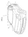
- FIG.1 is the perspective view showing a state where door mirror devices as outer mirrors for vehicle, each of which is provided with a lighting device for vehicle according to an embodiment of the present invention, are erected to a vehicle body.
- reference numeral 1 denotes a vehicle body
- 2 denotes a door mirror as an outer mirror for vehicle.
- the door mirror 2 has a lighting device including a housing body 3 which is configured to hold the door mirror 2 for rear viewing as shown in FIG.2 in an enlarged manner.
- the door mirror 2 is designed to be turnable between an erected state and a retracted state to the vehicle body 1.
- the housing body 3 has a shape curved backwardly (arrow A direction) from an inner end portion toward an outer end portion in a width direction of the vehicle body 1 at a rear surface side of the mirror 4 in an erected state.
- a base member 5 is provided inside the housing body 3. Positioning members 6 are provided with appropriate intervals on the base member 5 from the outer end portion toward the inner end portion in the width direction of the vehicle body 1.
- a circuit board 7 is provided on the positioning member 6. The circuit board 7 is positioned by the positioning member 6 and fixed on the base member 5 by a presser bar spring 8 and a locking screw 9.
- Light-emitting diodes (LED) 10 as light emitting devices are provided for the circuit board 7. The light-emitting diodes 10 arc arrayed from the outer end portion toward the inner end portion in the width direction of the vehicle body 1.
- An outer lens 11 as an outer member exposed on the rear surface side of the housing body 3 is provided on the base member 5.
- a decorating wall 12 is provided between the base member 5 and the outer lens 11.
- the decorating wall 12 is formed by resin molding, for example.
- Each of the light-emitting diodes 10 is arranged between the base member 5 and the decorating wall 12.
- a light transmitting portion 13 is formed on an area of the decorating wall 12 so as to face a light emission portion 10a of the light emitting diode 10.
- positioning peripheral walls 15, for example in a cylindrical shape, which position mask members 14 to prevent attachment of deposited matter on the light transmitting portions 13 when performing deposition are formed so as to surround the light transmitting portion 13 corresponding to the outer end portion in the width direction of the vehicle body 1 and residual light transmitting portions 13.
- a deposited surface is provided on at least one surface of the decorating wall excluding areas of the light transmitting portions.
- the deposited surface may be provided on a surface of the decorating wall, which faces the housing body or the outer lens, as well as provided on both surfaces.
- the deposited surface 12a which carries out decorating action when visually contacted from outside through the lens is formed on the surface facing the outer lens 11 and excluding areas of the light transmitting portions 13.
- Each light-emitting diode 10 is configured to output direct light P1, P2, P3 (see FIG.4) through the light transmitting portions 13 and the outer lens 11 in an angle range directing backward from the width direction of the vehicle body 1 so as to be visually contacted as one light source when simultaneously turned ON in the erected state of the housing body 3.
- direct light P1 and direct light P2 is used as light for turn signal.
- the decorating wall has a plurality of wall sections 112 on each of which the light transmitting portion is provided.
- the wall sections 112 have different inclinations from each other and are disposed to set light from the light emitting devices within the range of the predetermined light distribution angle.
- the decorating wall 12 is configured to have different structures of the light transmitting portion 13 depending on regions.
- the decorating wall 12 is manufactured via a manufacturing process described below, for example.
- a mold die is provided on a mold cavity (not shown) such that a transparent flat plate corresponding to the light transmitting portions 13 is obtained.
- a molded component having a shape corresponding to the decorating wall 12 is formed.
- the transparent flat plate of the molded component is masked by the mask members 14 shown in FIG.3. Then, aluminization is applied to at least one surface of the molded component excluding the masked areas of the transparent flat plate by using a deposition apparatus (not shown) to form the deposited surface 12a.
- the mask members 14 are removed from the molded component. Consequently, the decorating wall 12 where the light transmitting portions 13 are made of transparent flat plate and which has the deposited surface 12a is formed.
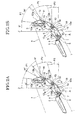
- the lighting device for vehicle 16 When a lighting device for vehicle 16 is manufactured by using the decorating wall 12, the lighting device for vehicle 16 corresponding to the region where the range of the light distribution angle is set from approximately 30 degrees to approximately 70 degrees in relation to the front-rear direction of the vehicle body 1 as a reference direction Z is obtained as shown in FIG.2A.
- a mold die to form a prism surface (not shown) is provided on the cavity of mold such that the prism surface is obtained in areas corresponding to the light transmitting portions 13 as light distribution windows. Consequently, a molded component having the shape corresponding to the decorating wall 12 is formed.
- the prism surface of the molded component is masked by the mask members 14.
- aluminization is applied to on the surface of the molded component excluding areas of the prism surface by using the deposition apparatus (not shown) to form the deposited surface 12a.
- the lighting device for vehicle 16 When the lighting device for vehicle 16 is manufactured by using the decorating wall 12, the lighting device for vehicle 16 corresponding to the region where the range of the light distribution angle is set from approximately 5 degrees to approximately 55 degrees in relation to the front-rear direction of the vehicle as a reference direction Z is obtained as shown in FIG.2B.
- the lighting device for vehicle 16 capable of flexibly being adjusted to regulations of each area having a different range of the distribution angle can be inexpensively manufactured. Furthermore, since the light-emitting diode 10 cannot be visually contacted directly via the outer lens 11, a decorating function can be improved by making light-emitting diodes become difficult to visually contact from outside.
- the configuration for manufacturing the lighting device for vehicle 16 capable of flexibly being adjusted to regulations of each area having a different range of the light distribution angle by forming the transparent flat plate or the prism surface on the light transmitting portions 13 of the decorating wall 12, is employed.
- the lighting device for vehicle is also capable of improving the decorating function by making light-emitting diodes become difficult to visually contact from outside.
- a configuration having the shape described below can be also employed as the decorating wall.
- the decorating wall 12 has openings 17 as the light transmitting portions 13 and positioning protrusions 18 as shown in FIG.4A.
- a mold die to form the openings 17 (not shown) and a mold die to form the positioning protrusions 18 (not shown) are provided on a cavity to form the decorating wall 12. Consequently, the molded component of the decorating wall 12 is formed.
- aluminization is applied to the surface of the decorating wall 12 excluding areas of the openings 17 by using the deposition apparatus (not shown) to form the deposited surface 12a. Consequently, the decorating wall 12 having the openings 17 and the positioning protrusions 18 is manufactured.
- the openings 17 themselves are used as the light transmitting portions 13. Furthermore, a specific prism body may be fixed to the openings 17.
- a prism body 19 which deflects light beam shown in FIG.4C is previously prepared by molding.
- the prism body 19 has a prism portion 19a and an attaching portion 19b.
- An attaching hole 19c to be fitted into the protrusion 18 is formed on the attaching portion 19b.
- the same mold in a case of manufacturing the lighting device for vehicle 16 corresponding to regulations having a different range of the light distribution angle depending on each area, the same mold can be used as a mode to be used in molding the decorating wall 12.
- the prism body 19 When the prism body 19 is installed to the opening 17 of the decorating wall 12, which is molded in the above-described manner, the range of the light distribution angle of the lighting device for vehicle 16 can be varied. Furthermore, even in a case where the regulations are changed, simply preparing the prism body 19 having a different refraction angle can adjust to the change. Therefore, the invention can flexibly be adjusted to the changes of regulations.
- the lighting device 16 capable of flexibly being adjusted to regulations of each area having a different range of the light distribution angle and capable of improving a decorating function by making the light-emitting diodes 10 become difficult to visually contact from outside.
- the configuration where the prism body is fixed to the opening 17 can be applied for the regulations of North America, and according to Example 2, the degree of freedom of the light distribution settings remarkably increases.
- an effect being capable of flexibly being adjusted to regulations of each area having a different range of a light distribution angle and making light-emitting diodes become difficult to visually contact from outside to improve the decorating function is exerted.
Landscapes
- Engineering & Computer Science (AREA)
- Mechanical Engineering (AREA)
- Multimedia (AREA)
- Lighting Device Outwards From Vehicle And Optical Signal (AREA)
- Non-Portable Lighting Devices Or Systems Thereof (AREA)
- Rear-View Mirror Devices That Are Mounted On The Exterior Of The Vehicle (AREA)
Applications Claiming Priority (1)
| Application Number | Priority Date | Filing Date | Title |
|---|---|---|---|
| JP2006298598A JP4631840B2 (ja) | 2006-11-02 | 2006-11-02 | 車両用灯具 |
Publications (3)
| Publication Number | Publication Date |
|---|---|
| EP1918159A2 true EP1918159A2 (de) | 2008-05-07 |
| EP1918159A3 EP1918159A3 (de) | 2008-06-11 |
| EP1918159B1 EP1918159B1 (de) | 2010-08-25 |
Family
ID=38781431
Family Applications (1)
| Application Number | Title | Priority Date | Filing Date |
|---|---|---|---|
| EP07119577A Not-in-force EP1918159B1 (de) | 2006-11-02 | 2007-10-30 | Beleuchtungsvorrichtung für ein Fahrzeug und Außenspiegelvorrichtung |
Country Status (6)
| Country | Link |
|---|---|
| US (1) | US7677776B2 (de) |
| EP (1) | EP1918159B1 (de) |
| JP (1) | JP4631840B2 (de) |
| KR (1) | KR100959551B1 (de) |
| CN (1) | CN101173745B (de) |
| DE (1) | DE602007008661D1 (de) |
Cited By (1)
| Publication number | Priority date | Publication date | Assignee | Title |
|---|---|---|---|---|
| EP2277741A1 (de) * | 2009-07-20 | 2011-01-26 | SMR Patents S.à.r.l. | Rückspiegel mit Lichtwellenleiter-Wendesignalanzeiger |
Families Citing this family (6)
| Publication number | Priority date | Publication date | Assignee | Title |
|---|---|---|---|---|
| JP4597082B2 (ja) * | 2006-03-22 | 2010-12-15 | 株式会社ミツバ | 車両用燈体 |
| KR101283196B1 (ko) * | 2010-12-01 | 2013-07-05 | 기아자동차주식회사 | 아웃사이드 미러용 턴 시그널 램프 |
| JP5906050B2 (ja) | 2011-09-30 | 2016-04-20 | 株式会社小糸製作所 | 車両用灯具 |
| DE102016114353A1 (de) * | 2016-08-03 | 2018-02-08 | Daimler Ag | Endkappe für eine beleuchtete Zierleistenanordnung sowie Zierleistenanordnung |
| CN107878353A (zh) * | 2016-09-30 | 2018-04-06 | 上汽通用汽车有限公司 | 配光镜及其安装方法 |
| JP2024158524A (ja) * | 2023-04-27 | 2024-11-08 | 美里工業株式会社 | 車両用ドアミラー及びその製造方法 |
Family Cites Families (33)
| Publication number | Priority date | Publication date | Assignee | Title |
|---|---|---|---|---|
| JPH0388220U (de) * | 1989-12-25 | 1991-09-10 | ||
| US5278731A (en) * | 1992-09-10 | 1994-01-11 | General Electric Company | Fiber optic lighting system using conventional headlamp structures |
| FR2707223B1 (fr) * | 1993-07-07 | 1995-09-29 | Valeo Vision | Feu de signalisation perfectionné à diodes électroluminescentes. |
| DE4417695C2 (de) * | 1994-05-20 | 1998-01-29 | Reitter & Schefenacker Gmbh | Kraftfahrzeugleuchte |
| JPH09306219A (ja) * | 1996-05-13 | 1997-11-28 | Yamaha Motor Co Ltd | ヘッドライト装置 |
| DE29702746U1 (de) * | 1997-02-18 | 1997-04-03 | Reitter & Schefenacker GmbH & Co. KG, 73730 Esslingen | Außenrückblickspiegel für Fahrzeuge, vorzugsweise für Kraftfahrzeuge |
| FR2776595B1 (fr) * | 1998-03-31 | 2000-06-16 | Valeo Vision | Feu de signalisation comprenant plusieurs sources lumineuses |
| EP0972677A3 (de) | 1998-07-17 | 2000-12-20 | Hella KG Hueck & Co. | Fahrzeugleuchte |
| DE19933724A1 (de) | 1999-07-19 | 2001-02-01 | Fer Fahrzeugelektrik Gmbh | Seitenblinkleuchte |
| EP1077344A3 (de) | 1999-08-16 | 2004-01-28 | FER Fahrzeugelektrik GmbH | Leuchte |
| EP1118813B1 (de) * | 2000-01-21 | 2008-10-08 | Stanley Electric Co., Ltd. | Signalleuchte für Kraftfahrzeuge |
| DE20001407U1 (de) * | 2000-01-27 | 2000-03-16 | Reitter & Schefenacker GmbH & Co. KG, 73730 Esslingen | Außenrückblickspiegel für Fahrzeuge, vorzugsweise für Kraftfahrzeuge |
| ES2168071B1 (es) * | 2000-07-12 | 2003-07-16 | Barros Alejandro Rodriguez | Retrovisor modular con señales multiples intercambiables para vehiculos de 2, 3, 4 o mas ruedas. |
| JP2002075025A (ja) * | 2000-08-25 | 2002-03-15 | Stanley Electric Co Ltd | 車両用led灯具 |
| JP4144170B2 (ja) | 2000-09-08 | 2008-09-03 | 市光工業株式会社 | ドアミラー用のサイドターンランプ |
| ES2278670T3 (es) * | 2000-10-04 | 2007-08-16 | Fer Fahrzeugelektrik Gmbh | Luz intermitente lateral. |
| FR2820273B1 (fr) * | 2001-01-29 | 2006-07-28 | Koito Mfg Co Ltd | Diode photoemissive et lampe a diodes pour automobile |
| MXPA03008637A (es) * | 2001-03-27 | 2005-03-07 | Meridian Automotive Sys Inc | Montaje de lampara vehicular con estructura simplificada y chmsl y lampara trasera que incorpora el mismo. |
| JP2002362222A (ja) * | 2001-05-31 | 2002-12-18 | Tokai Rika Co Ltd | アウタミラーのターンシグナル付きバイザカバー構造 |
| US6637921B2 (en) * | 2001-09-28 | 2003-10-28 | Osram Sylvania Inc. | Replaceable LED bulb with interchangeable lens optic |
| US6846100B2 (en) | 2002-02-25 | 2005-01-25 | Norifumi Imazeki | Lighting fixture for vehicles |
| JP3998999B2 (ja) | 2002-03-06 | 2007-10-31 | 株式会社小糸製作所 | 車両用灯具 |
| US6769798B2 (en) * | 2002-04-11 | 2004-08-03 | E'sam Co.,. Ltd. | Side mirror cover and cover lamp to be used therefor |
| JP2004210236A (ja) * | 2003-01-08 | 2004-07-29 | Ichikoh Ind Ltd | アウターミラーハウジングおよびアウターミラーカバー |
| JP4110989B2 (ja) * | 2003-02-03 | 2008-07-02 | 市光工業株式会社 | ランプ付きアウトサイドミラー装置 |
| US6758582B1 (en) * | 2003-03-19 | 2004-07-06 | Elumina Technology Incorporation | LED lighting device |
| JP2005067391A (ja) * | 2003-08-25 | 2005-03-17 | Sakae Riken Kogyo Co Ltd | ターンシグナルランプ付きドアミラー装置 |
| JP2005190716A (ja) * | 2003-12-24 | 2005-07-14 | Ichikoh Ind Ltd | 車両用アウトサイドミラー装置 |
| JP4239839B2 (ja) * | 2004-02-02 | 2009-03-18 | 市光工業株式会社 | 車両用アウトサイドミラー装置 |
| US7513664B2 (en) * | 2004-05-10 | 2009-04-07 | Ichikoh Industries, Ltd. | Outside mirror apparatus including lighting device for vehicle |
| JP4218611B2 (ja) * | 2004-08-06 | 2009-02-04 | 市光工業株式会社 | 車両用灯具、車両用灯具付き車両用アウトサイドミラー装置 |
| JP4413764B2 (ja) * | 2004-12-10 | 2010-02-10 | 株式会社小糸製作所 | 車両用灯具 |
| DE102005012104A1 (de) | 2005-03-10 | 2006-09-14 | Schefenacker Vision Systems Germany Gmbh | Gehäuse, insbesondere Spiegelgehäuse |
-
2006
- 2006-11-02 JP JP2006298598A patent/JP4631840B2/ja not_active Expired - Fee Related
-
2007
- 2007-08-23 CN CN2007101466494A patent/CN101173745B/zh not_active Expired - Fee Related
- 2007-09-03 KR KR1020070088953A patent/KR100959551B1/ko not_active Expired - Fee Related
- 2007-10-29 US US11/926,408 patent/US7677776B2/en not_active Expired - Fee Related
- 2007-10-30 DE DE602007008661T patent/DE602007008661D1/de active Active
- 2007-10-30 EP EP07119577A patent/EP1918159B1/de not_active Not-in-force
Cited By (2)
| Publication number | Priority date | Publication date | Assignee | Title |
|---|---|---|---|---|
| EP2277741A1 (de) * | 2009-07-20 | 2011-01-26 | SMR Patents S.à.r.l. | Rückspiegel mit Lichtwellenleiter-Wendesignalanzeiger |
| US8177401B2 (en) | 2009-07-20 | 2012-05-15 | Smr Patents S.A.R.L. | Light guide turn signal indicator rear view mirror |
Also Published As
| Publication number | Publication date |
|---|---|
| CN101173745B (zh) | 2011-05-18 |
| EP1918159A3 (de) | 2008-06-11 |
| US7677776B2 (en) | 2010-03-16 |
| EP1918159B1 (de) | 2010-08-25 |
| JP4631840B2 (ja) | 2011-02-16 |
| KR100959551B1 (ko) | 2010-05-27 |
| JP2008114677A (ja) | 2008-05-22 |
| KR20080040559A (ko) | 2008-05-08 |
| CN101173745A (zh) | 2008-05-07 |
| US20080259624A1 (en) | 2008-10-23 |
| DE602007008661D1 (de) | 2010-10-07 |
Similar Documents
| Publication | Publication Date | Title |
|---|---|---|
| EP1918159B1 (de) | Beleuchtungsvorrichtung für ein Fahrzeug und Außenspiegelvorrichtung | |
| US8382351B2 (en) | Vehicle lamp | |
| US6499870B1 (en) | Tail light for a motor vehicle | |
| EP2377720B1 (de) | Lichtleitervorrichtung zur Verwendung in Automobilen | |
| US6746634B2 (en) | Vehicular lamp and injection mold and manufacturing method for lamp body of vehicular lamp | |
| US7220030B2 (en) | Exterior mirror having lamp and exterior rear-view mirror having lamp | |
| EP3599418B1 (de) | Fahrzeuglampe umfassend einen lichtleiter | |
| EP0922903B1 (de) | Heck-Mehrkammerleuchte für Fahrzeug | |
| WO2023046275A1 (en) | Self-illuminated frontend panel for a vehicle | |
| CN111868435B (zh) | 用于车辆的照明装置 | |
| CN114207349A (zh) | 车辆用照明装置 | |
| EP1559614B1 (de) | Aussenrückspiegel für Fahrzeuge und Beleuchtungseinrichtung für einen solchen Aussenrückspiegel | |
| CN118251569A (zh) | 用于车辆的照明装置的光模块 | |
| JP5060879B2 (ja) | 車両用室内灯 | |
| US10391930B2 (en) | Vehicular lamp and vehicular exterior rear view device | |
| CN217329634U (zh) | 一种车灯光学结构及具有其的车辆 | |
| JP7666892B2 (ja) | Bsmユニット | |
| EP3561374B1 (de) | Fahrzeuglampe | |
| JPH08125218A (ja) | 光半導体装置 | |
| CN218367589U (zh) | 后视镜指示灯灯壳、后视镜指示灯、后视镜和车辆 | |
| JP7491754B2 (ja) | 車輌用灯具 | |
| JP2024118630A (ja) | 車両用灯具 | |
| KR100405811B1 (ko) | 차폭등 | |
| CN121932624A (zh) | 用于车辆的照明设备 | |
| CN121761276A (zh) | 安装结构、车灯总成及车辆 |
Legal Events
| Date | Code | Title | Description |
|---|---|---|---|
| PUAI | Public reference made under article 153(3) epc to a published international application that has entered the european phase |
Free format text: ORIGINAL CODE: 0009012 |
|
| 17P | Request for examination filed |
Effective date: 20071030 |
|
| AK | Designated contracting states |
Kind code of ref document: A2 Designated state(s): AT BE BG CH CY CZ DE DK EE ES FI FR GB GR HU IE IS IT LI LT LU LV MC MT NL PL PT RO SE SI SK TR |
|
| AX | Request for extension of the european patent |
Extension state: AL BA HR MK RS |
|
| PUAL | Search report despatched |
Free format text: ORIGINAL CODE: 0009013 |
|
| AK | Designated contracting states |
Kind code of ref document: A3 Designated state(s): AT BE BG CH CY CZ DE DK EE ES FI FR GB GR HU IE IS IT LI LT LU LV MC MT NL PL PT RO SE SI SK TR |
|
| AX | Request for extension of the european patent |
Extension state: AL BA HR MK RS |
|
| 17Q | First examination report despatched |
Effective date: 20081222 |
|
| AKX | Designation fees paid |
Designated state(s): DE FR GB |
|
| GRAP | Despatch of communication of intention to grant a patent |
Free format text: ORIGINAL CODE: EPIDOSNIGR1 |
|
| GRAS | Grant fee paid |
Free format text: ORIGINAL CODE: EPIDOSNIGR3 |
|
| GRAA | (expected) grant |
Free format text: ORIGINAL CODE: 0009210 |
|
| AK | Designated contracting states |
Kind code of ref document: B1 Designated state(s): DE FR GB |
|
| REG | Reference to a national code |
Ref country code: GB Ref legal event code: FG4D |
|
| REF | Corresponds to: |
Ref document number: 602007008661 Country of ref document: DE Date of ref document: 20101007 Kind code of ref document: P |
|
| PLBE | No opposition filed within time limit |
Free format text: ORIGINAL CODE: 0009261 |
|
| STAA | Information on the status of an ep patent application or granted ep patent |
Free format text: STATUS: NO OPPOSITION FILED WITHIN TIME LIMIT |
|
| 26N | No opposition filed |
Effective date: 20110526 |
|
| REG | Reference to a national code |
Ref country code: DE Ref legal event code: R097 Ref document number: 602007008661 Country of ref document: DE Effective date: 20110526 |
|
| PGFP | Annual fee paid to national office [announced via postgrant information from national office to epo] |
Ref country code: FR Payment date: 20121018 Year of fee payment: 6 |
|
| PGFP | Annual fee paid to national office [announced via postgrant information from national office to epo] |
Ref country code: GB Payment date: 20121024 Year of fee payment: 6 |
|
| PGFP | Annual fee paid to national office [announced via postgrant information from national office to epo] |
Ref country code: DE Payment date: 20131023 Year of fee payment: 7 |
|
| GBPC | Gb: european patent ceased through non-payment of renewal fee |
Effective date: 20131030 |
|
| PG25 | Lapsed in a contracting state [announced via postgrant information from national office to epo] |
Ref country code: GB Free format text: LAPSE BECAUSE OF NON-PAYMENT OF DUE FEES Effective date: 20131030 |
|
| REG | Reference to a national code |
Ref country code: FR Ref legal event code: ST Effective date: 20140630 |
|
| PG25 | Lapsed in a contracting state [announced via postgrant information from national office to epo] |
Ref country code: FR Free format text: LAPSE BECAUSE OF NON-PAYMENT OF DUE FEES Effective date: 20131031 |
|
| REG | Reference to a national code |
Ref country code: DE Ref legal event code: R119 Ref document number: 602007008661 Country of ref document: DE |
|
| PG25 | Lapsed in a contracting state [announced via postgrant information from national office to epo] |
Ref country code: DE Free format text: LAPSE BECAUSE OF NON-PAYMENT OF DUE FEES Effective date: 20150501 |