EP1916484A2 - Heißwasservorrichtung für eine Badewanne - Google Patents
Heißwasservorrichtung für eine Badewanne Download PDFInfo
- Publication number
- EP1916484A2 EP1916484A2 EP20070118206 EP07118206A EP1916484A2 EP 1916484 A2 EP1916484 A2 EP 1916484A2 EP 20070118206 EP20070118206 EP 20070118206 EP 07118206 A EP07118206 A EP 07118206A EP 1916484 A2 EP1916484 A2 EP 1916484A2
- Authority
- EP
- European Patent Office
- Prior art keywords
- temperature
- bathtub
- water
- hot water
- outdoor air
- Prior art date
- Legal status (The legal status is an assumption and is not a legal conclusion. Google has not performed a legal analysis and makes no representation as to the accuracy of the status listed.)
- Withdrawn
Links
- XLYOFNOQVPJJNP-UHFFFAOYSA-N water Substances O XLYOFNOQVPJJNP-UHFFFAOYSA-N 0.000 title claims abstract description 231
- 238000003287 bathing Methods 0.000 abstract description 16
- 239000003507 refrigerant Substances 0.000 description 16
- 238000001514 detection method Methods 0.000 description 3
- CURLTUGMZLYLDI-UHFFFAOYSA-N Carbon dioxide Chemical compound O=C=O CURLTUGMZLYLDI-UHFFFAOYSA-N 0.000 description 2
- 229910002092 carbon dioxide Inorganic materials 0.000 description 1
- 239000001569 carbon dioxide Substances 0.000 description 1
Images
Classifications
-
- F—MECHANICAL ENGINEERING; LIGHTING; HEATING; WEAPONS; BLASTING
- F24—HEATING; RANGES; VENTILATING
- F24D—DOMESTIC- OR SPACE-HEATING SYSTEMS, e.g. CENTRAL HEATING SYSTEMS; DOMESTIC HOT-WATER SUPPLY SYSTEMS; ELEMENTS OR COMPONENTS THEREFOR
- F24D19/00—Details
- F24D19/10—Arrangement or mounting of control or safety devices
- F24D19/1006—Arrangement or mounting of control or safety devices for water heating systems
- F24D19/1051—Arrangement or mounting of control or safety devices for water heating systems for domestic hot water
-
- E—FIXED CONSTRUCTIONS
- E03—WATER SUPPLY; SEWERAGE
- E03C—DOMESTIC PLUMBING INSTALLATIONS FOR FRESH WATER OR WASTE WATER; SINKS
- E03C1/00—Domestic plumbing installations for fresh water or waste water; Sinks
- E03C1/02—Plumbing installations for fresh water
- E03C1/04—Water-basin installations specially adapted to wash-basins or baths
- E03C1/044—Water-basin installations specially adapted to wash-basins or baths having a heating or cooling apparatus in the supply line
-
- F—MECHANICAL ENGINEERING; LIGHTING; HEATING; WEAPONS; BLASTING
- F24—HEATING; RANGES; VENTILATING
- F24D—DOMESTIC- OR SPACE-HEATING SYSTEMS, e.g. CENTRAL HEATING SYSTEMS; DOMESTIC HOT-WATER SUPPLY SYSTEMS; ELEMENTS OR COMPONENTS THEREFOR
- F24D17/00—Domestic hot-water supply systems
- F24D17/02—Domestic hot-water supply systems using heat pumps
-
- F—MECHANICAL ENGINEERING; LIGHTING; HEATING; WEAPONS; BLASTING
- F24—HEATING; RANGES; VENTILATING
- F24H—FLUID HEATERS, e.g. WATER OR AIR HEATERS, HAVING HEAT-GENERATING MEANS, e.g. HEAT PUMPS, IN GENERAL
- F24H15/00—Control of fluid heaters
- F24H15/20—Control of fluid heaters characterised by control inputs
- F24H15/258—Outdoor temperature
-
- F—MECHANICAL ENGINEERING; LIGHTING; HEATING; WEAPONS; BLASTING
- F24—HEATING; RANGES; VENTILATING
- F24H—FLUID HEATERS, e.g. WATER OR AIR HEATERS, HAVING HEAT-GENERATING MEANS, e.g. HEAT PUMPS, IN GENERAL
- F24H15/00—Control of fluid heaters
- F24H15/30—Control of fluid heaters characterised by control outputs; characterised by the components to be controlled
- F24H15/375—Control of heat pumps
- F24H15/38—Control of compressors of heat pumps
-
- F—MECHANICAL ENGINEERING; LIGHTING; HEATING; WEAPONS; BLASTING
- F24—HEATING; RANGES; VENTILATING
- F24H—FLUID HEATERS, e.g. WATER OR AIR HEATERS, HAVING HEAT-GENERATING MEANS, e.g. HEAT PUMPS, IN GENERAL
- F24H15/00—Control of fluid heaters
- F24H15/40—Control of fluid heaters characterised by the type of controllers
- F24H15/414—Control of fluid heaters characterised by the type of controllers using electronic processing, e.g. computer-based
-
- F—MECHANICAL ENGINEERING; LIGHTING; HEATING; WEAPONS; BLASTING
- F24—HEATING; RANGES; VENTILATING
- F24H—FLUID HEATERS, e.g. WATER OR AIR HEATERS, HAVING HEAT-GENERATING MEANS, e.g. HEAT PUMPS, IN GENERAL
- F24H15/00—Control of fluid heaters
- F24H15/40—Control of fluid heaters characterised by the type of controllers
- F24H15/486—Control of fluid heaters characterised by the type of controllers using timers
-
- Y—GENERAL TAGGING OF NEW TECHNOLOGICAL DEVELOPMENTS; GENERAL TAGGING OF CROSS-SECTIONAL TECHNOLOGIES SPANNING OVER SEVERAL SECTIONS OF THE IPC; TECHNICAL SUBJECTS COVERED BY FORMER USPC CROSS-REFERENCE ART COLLECTIONS [XRACs] AND DIGESTS
- Y10—TECHNICAL SUBJECTS COVERED BY FORMER USPC
- Y10T—TECHNICAL SUBJECTS COVERED BY FORMER US CLASSIFICATION
- Y10T137/00—Fluid handling
- Y10T137/8158—With indicator, register, recorder, alarm or inspection means
Definitions
- the present invention relates to a hot water device for bathtub for home or professional use.
- a hot water device for bathtub of this type there has been known one which includes a hot water storage tank which stores high-temperature water, water supplying means for supplying low-temperature water, a temperature sensor which detects an outdoor air temperature, a timer which detects a time zone of day, and control means for controlling the operation of a compressor (for example, Japanese Patent Publication 2001-201177 ).
- control means controls the operation of the compressor based on an outdoor air temperature detected by the temperature sensor and a time zone of day detected by the timer, whereby high-temperature water is stored in the hot water storage tank.
- the hot water device for bathtub high-temperature water stored in the hot water storage tank and low-temperature water supplied from the water supplying means are mixed to obtain water for bathtub of a preliminarily determined preset temperature, and thereafter the water for bathtub of the preset temperature is supplied to the bathtub.
- the preset temperature of water for bathtub may be higher than a temperature desired by the user during bathing. In this case, adjustment must be made to obtain the temperature desired by the user by further supplying low-temperature water from the water supplying means to the bathtub.
- the preset temperature of water for bathtub may be lower than a temperature desired by the user during bathing. In this case, adjustment must be made to obtain the temperature desired by the user by further supplying high-temperature water stored in the hot water storage tank to the bathtub.
- the present invention has been achieved in view of the above-mentioned circumstances, and has an object to provide a hot water device for bathtub in which water is not wasted to allow energy saving and at the same time it is possible to save a trouble of adjusting the temperature of water for bathtub supplied to the bathtub to a temperature desired by the user during bathing.
- a hot water device for bathtub which includes a hot water storage tank which stores high-temperature water, water supplying means for supplying low-temperature water, and temperature setting means allowing setting of the temperature of water for bathtub to be supplied to a bathtub, the hot water device for bathtub mixing high-temperature water supplied from the hot water storage tank and low-temperature water supplied from the water supplying means and then supplying water for bathtub of a preset temperature to the bathtub, and the hot water device for bathtub including outdoor air temperature information acquiring means for acquiring prescribed information on outdoor air temperature, and control means for varying the temperature of water for bathtub to a temperature lower than the preset temperature when the outside air temperature acquired by the outdoor air temperature information acquiring means is higher than a prescribed reference temperature, or varying the temperature of water for bathtub to a temperature higher than the preset temperature when the outside air temperature acquired by the outdoor air temperature information acquiring means is lower than the prescribed reference temperature.
- the inventive hot water device for bathtub prescribed information on outdoor air temperature is acquired by the outdoor air temperature information acquiring means, and when the outdoor air temperature acquired by the outdoor air temperature information acquiring means is higher or lower than a prescribed reference temperature, water for bathtub having its temperature varied by the control means to a temperature desired by the user during bathing is supplied to the bathtub. Accordingly, temperature adjustment which uses water is not needed, so water is not wasted to achieve energy saving, and at the same time it is possible to save a trouble of adjusting the water in the bathtub to a temperature desired by the user during bathing.
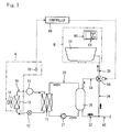
- FIGS. 1 and 2 illustrate a hot water device for bathtub according to an embodiment of the present invention.
- the hot water device for bathtub includes: a refrigerant circuit 10 in which refrigerant circulates; hot water circuit 20 in which hot water circulates; a hot water storage tank 30 which stores high-temperature water; water supplying tube 40 acting as means for supplying low-temperature water; a mixing valve 50 which mixes high-temperature water supplied from the hot water storage tank 30 and low-temperature water supplied from the water supplying tube 40; a remote controller 60 acting as temperature setting means allowing setting of the temperature of water for bathtub to be supplied to a later described bathtub 51; an outdoor air temperature sensor 70 acting as outdoor air temperature information acquiring means for acquiring information on outdoor air temperature; and a controller 80 acting as control means.
- the refrigerant circuit 10 is constituted of a compressor 11, an expansion valve 12 acting as an expansion mechanism, an air heat exchanger 13 and a water heat exchanger 15; refrigerant circulates through the compressor 11, the water heat exchanger 15, the expansion valve 12, the air heat exchanger 13 and the compressor 11 in this order.
- the air heat exchanger 13 is arranged in an outdoor site A (refer to a part surrounded by the dashed-dotted line in FIG. 1), and there is provided a fan 14 for carrying out heat exchange between the refrigerant and outside air in the air heat exchanger 13.
- the refrigerant used in the refrigerant circuit 10 is natural one (for example, carbon dioxide).
- the hot water circuit 20 is constituted of a first pump 21, the hot water storage tank 30 and the water heat exchanger 15; hot water circulates through the hot water storage tank 30, the first pump 21, the water heat exchanger 15 and the hot water storage tank 30 in this order. That is, the water heat exchanger 15 is shared by the refrigerant circuit 10 and the hot water circuit 20; heat exchange is carried out between the refrigerant circulating in the refrigerant circuit 10 and the hot water circulating in the hot water circuit 20.
- the hot water storage tank 30 is connected to the hot water circuit 20, and via a first flow path 32 to the water supplying tube 40, and via a second flow path 33 to the mixing valve 50. Accordingly, low-temperature water is supplied from the water supplying tube 40 via the first flow path 32 to the hot water storage tank 30 and then circulates in the hot water circuit 20, so that the low-temperature water changes to high-temperature water, and thereafter returns to the hot water storage tank 30 to be sent via the second flow path 33 to the mixing valve 50.
- the water supplying tube 40 has one end thereof connected to a supply source such as a water line (not illustrated). And the water supplying tube 40 has the other end thereof branching into the first flow path 32 and a third flow path 34, the water supplying tube 40 is connected via the first flow path 32 to the hot water storage tank 30, and via the third flow path 34 to the mixing valve 50. Accordingly, low-temperature water is supplied to both the hot water storage tank 30 and the mixing valve 50 (refer to the arrow of thick line in FIG. 1).
- the mixing valve 50 is connected via the second flow path 33 to the hot water storage tank 30, and via the third flow path 34 to the water supplying tube 40, and via a fourth flow path 35 to a bathtub 51. Accordingly, high-temperature water supplied via the second flow path 33 from the hot water storage tank 30 and low-temperature water supplied via the third flow path 34 from the water supplying tube 40 are mixed at the mixing valve 50 to provide water for bathtub.
- the water for bathtub provided at the mixing valve 50 is supplied via the fourth flow path 35 to the bathtub 51.
- the remote controller 60 is arranged within a bathroom B (refer to a part surrounded by the two-dot chain line in FIG. 1) along with the bathtub 51.
- the remote controller 60 is provided with an operating switch 61 used to start the operation, to adjust the temperature of water for bathtub filling the bathtub 51, or to make a water filling reservation.
- the operating switch 61 of the remote controller 60 the user can start the operation of the hot water device for bathtub, set preset temperature Tb of hot water to be filled into the bathtub 51, or set a start time of filling hot water.
- the outdoor air temperature sensor 70 serves to detect outdoor air temperature Ta being information on outdoor air temperature.
- the temperature of water for bathtub to be supplied to the bathtub 51 is varied according to outdoor air temperature Ta detected by the outdoor air temperature sensor 70.
- any existing temperature sensor can be used as the outdoor air temperature sensor 70.
- the controller 80 acting as control means for controlling the operation of the hot water device for bathtub includes a microcomputer and various types of drivers.
- a detection signal is sent to the controller 80 based on outdoor air temperature Ta detected by the outdoor air temperature sensor 70.
- a detection signal is sent to the controller 80 based on a water filling reservation time detected by a timer (not illustrated).
- the controller 80 controls the opening of the mixing valve 50 and the supplying of power to the compressor 11, so that the temperature of water for bathtub to be supplied to the bathtub 51 is varied as described later.
- the refrigerant of the refrigerant circuit 10 circulates through the compressor 11, the water heat exchanger 15, the expansion valve 12, the air heat exchanger 13 and the compressor 11 in this order (refer to the arrow of solid line in FIG. 1).
- the hot water of the hot water circuit 20 circulates through the hot water storage tank 30, the first pump 21, the water heat exchanger 15 and the hot water storage tank 30 in this order (refer to the outlined arrow in FIG. 1).
- the mixing valve 50 the high-temperature water supplied from the hot water storage tank 30 and the low-temperature water supplied from the water supplying tube 40 are mixed.
- the opening of the mixing valve 50 is controlled by the controller 80 according to outdoor air temperature Ta detected by the outdoor air temperature sensor 70, so that the temperature of water for bathtub to be supplied to the bathtub 51 is varied.
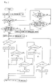
- the control of the opening of the mixing valve 50 by the controller 80 will be described below.
- step S1 First the user operates the operating switch 61 to set preset temperature Tb of hot water filled into the bathtub 51 (step S1).
- the controller 80 determines whether the operating switch 61 of the remote controller 60 has been turned on by the user (step S2).
- step S3 if the operating switch 61 of the remote controller 60 has been turned on by the user, the controller 80 determines whether or not the outdoor air temperature sensor 70 has been turned on during the past hour (step S3). That is, the controller 80 determines whether or not the outdoor air temperature sensor 70 has been in a state capable of detecting outdoor air temperature Ta during the past hour.
- step S2 if the operating switch 61 of the remote controller 60 has not been turned on by the user, the controller 80 determines whether or not a water filling reservation time has been set (step S4).
- step S4 if a water filling reservation time has been set, the controller 80 determines whether there remain 30 minutes or less until the water filling reservation time (step S5). At step S4, if no water filling reservation time has been set, the flow returns to step S2.
- step S5 if there remain 30 minutes or less until the water filling reservation time, the flow returns to step S3. Also, at step S5, if no water filling reservation time has been set, the flow returns to step S2.
- step S3 if the outdoor air temperature sensor 70 has not been turned on during the past hour, the outdoor air temperature sensor 70 is turned on so that outdoor air temperature Ta can be detected (step S8), and the flow returns to step S6.
- the controller 80 controls the opening of the mixing valve 50 so that the temperature of water for bathtub becomes lower by a predetermined value (for example, 2°C) than hot water filling preset temperature Tb, and varies the temperature of water for bathtub to temperature Tc desired by the user during bathing (step S9). That is, when high-temperature water and low-temperature water is mixed at the mixing valve 50, the opening of the mixing valve 50 is controlled by the controller 80 so that the temperature of water for bathtub to be supplied to the bathtub 51 becomes Tc lower by 2°C than hot water filling preset temperature Tb, and thus more low-temperature water is imported.
- a predetermined value for example, 2°C
- step S10 if the detected outdoor air temperature Ta is equal to or higher than prescribed outdoor air reference temperature T2 and at the same time lower than prescribed outdoor air reference temperature T1, the controller 80 controls the opening of the mixing valve 50 so that the temperature of water for bathtub becomes lower by a predetermined value (for example, 1°C) than hot water filling preset temperature Tb, and varies the temperature of water for bathtub to temperature Td desired by the user during bathing (step S11). That is, when high-temperature water and low-temperature water is mixed at the mixing valve 50, the opening of the mixing valve 50 is controlled by the controller 80 so that the temperature of water for bathtub to be supplied to the bathtub 51 becomes Td lower by 1°C than hot water filling preset temperature Tb, and thus more low-temperature water is imported.
- a predetermined value for example, 1°C
- step S12 if the detected outdoor air temperature Ta is equal to or higher than prescribed outdoor air reference temperature T3 and at the same time lower than prescribed outdoor air reference temperature T2, the temperature of water for bathtub is varied to temperature Te equal to hot water filling preset temperature Tb (step S13). That is, if the detected outdoor air temperature Ta is equal to or higher than prescribed outdoor air reference temperature T3 and at the same time lower than prescribed outdoor air reference temperature T2, the temperature adjustment relative to hot water filling preset temperature Tb is not made.
- step S14 if the detected outdoor air temperature Ta is equal to or higher than prescribed outdoor air reference temperature T4 and at the same time lower than prescribed outdoor air reference temperature T3, the controller 80 controls the opening of the mixing valve 50 so that the temperature of water for bathtub becomes higher by a predetermined value (for example, 1°C) than hot water filling preset temperature Tb, and varies the temperature of water for bathtub to temperature Tf desired by the user during bathing (step S15). That is, when high-temperature water and low-temperature water is mixed at the mixing valve 50, the opening of the mixing valve 50 is controlled by the controller 80 so that the temperature of water for bathtub to be supplied to the bathtub 51 becomes Tf higher by 1°C than hot water filling preset temperature Tb, and thus more high-temperature water is imported.
- a predetermined value for example, 1°C
- step S14 if the detected outdoor air temperature Ta is equal to or higher than prescribed outdoor air reference temperature T4 and at the same time not lower than prescribed outdoor air reference temperature T3, it is determined whether or not the detected outdoor air temperature Ta is lower than prescribed outdoor air reference temperature T4 (step S16).
- step S16 if the detected outdoor air temperature Ta is lower than prescribed outdoor air reference temperature T4, the controller 80 controls the opening of the mixing valve 50 so that the temperature of water for bathtub becomes higher by a predetermined value (for example, 2°C) than hot water filling preset temperature Tb, and varies the temperature of water for bathtub to temperature Tg desired by the user during bathing (step S17). That is, when high-temperature water and low-temperature water is mixed at the mixing valve 50, the opening of the mixing valve 50 is controlled by the controller 80 so that the temperature of water for bathtub to be supplied to the bathtub 51 becomes Tg higher by 2°C than hot water filling preset temperature Tb, and thus more high-temperature water is imported. Meanwhile, at step S16, if the detected outdoor air temperature Ta is not lower than prescribed outdoor air reference temperature T4, and the flow returns to step S7.
- a predetermined value for example, 2°C
- the water for bathtub having its temperature varied as described above to temperature Tc, Td, Te, Tf or Tg (Tc ⁇ Td ⁇ Te ⁇ Tf ⁇ Tg) desired by the user during bathing in the mixing valve 50 according to the detected outdoor air temperature Ta is supplied via the fourth flow path 35 to the bathtub 51 (refer to the arrow of dashed-dotted line in FIG. 1) to start automatic filling of hot water.
- the water for bathtub having its temperature varied by the controller 80 to temperature Tc, Td, Te, Tf or Tg desired by the user during bathing is supplied to the bathtub 51. Accordingly, the temperature adjustment using water is not needed, and thus water is not wasted to allow energy saving and at the same time it is possible to save a trouble of adjusting the temperature of hot water in the bathtub to a temperature desired by the user during bathing.
- any existing temperature sensor can be used as the outdoor air temperature sensor 70, component cost can be suppressed.
- the outdoor air temperature information acquiring means the outdoor air temperature sensor 70 detecting outdoor air temperature Ta is used, but the outdoor air temperature information acquiring means is not limited thereto as long as information on outdoor air temperature Ta can be acquired.
- the outdoor air temperature information acquiring means may acquire outdoor air temperature 1a from predetermined meteorological data.
- the temperature of water for bathtub supplied to the bathtub 51 is varied according to outdoor air temperature Ta detected by the outdoor air temperature sensor 70, but the present invention is not limited thereto.
- the operation of the compressor 11 or the first pump 21 may be controlled according to outdoor air temperature Ta detected by the outdoor air temperature sensor 70, in this case, energy saving can also be achieved in storing high-temperature water in the hot water storage tank 30.
- heat exchange is carried out between the refrigerant circulating in the refrigerant circuit 10 using external heat and the hot water circulating in the hot water circuit 20, but the present invention is not limited thereto.
- the heat exchange of hot water may be carried out by a gas hot water device or the like.
Landscapes
- Engineering & Computer Science (AREA)
- Physics & Mathematics (AREA)
- Thermal Sciences (AREA)
- Chemical & Material Sciences (AREA)
- Combustion & Propulsion (AREA)
- Mechanical Engineering (AREA)
- General Engineering & Computer Science (AREA)
- Life Sciences & Earth Sciences (AREA)
- Health & Medical Sciences (AREA)
- Hydrology & Water Resources (AREA)
- Public Health (AREA)
- Water Supply & Treatment (AREA)
- Computer Hardware Design (AREA)
- Control For Baths (AREA)
- Heat-Pump Type And Storage Water Heaters (AREA)
- Domestic Hot-Water Supply Systems And Details Of Heating Systems (AREA)
Applications Claiming Priority (1)
| Application Number | Priority Date | Filing Date | Title |
|---|---|---|---|
| JP2006289984A JP2008106998A (ja) | 2006-10-25 | 2006-10-25 | 浴槽用給湯装置 |
Publications (1)
| Publication Number | Publication Date |
|---|---|
| EP1916484A2 true EP1916484A2 (de) | 2008-04-30 |
Family
ID=39047608
Family Applications (1)
| Application Number | Title | Priority Date | Filing Date |
|---|---|---|---|
| EP20070118206 Withdrawn EP1916484A2 (de) | 2006-10-25 | 2007-10-10 | Heißwasservorrichtung für eine Badewanne |
Country Status (3)
| Country | Link |
|---|---|
| US (1) | US20080142094A1 (de) |
| EP (1) | EP1916484A2 (de) |
| JP (1) | JP2008106998A (de) |
Cited By (1)
| Publication number | Priority date | Publication date | Assignee | Title |
|---|---|---|---|---|
| CN110100065A (zh) * | 2016-12-30 | 2019-08-06 | 戈约萨股份公司 | 管理单元清洗设施 |
Families Citing this family (4)
| Publication number | Priority date | Publication date | Assignee | Title |
|---|---|---|---|---|
| US20130160200A1 (en) * | 2011-12-26 | 2013-06-27 | Richard Kim Cho | Constant Temperature Tub (CTT) |
| JP2018084377A (ja) * | 2016-11-24 | 2018-05-31 | 三菱電機株式会社 | 貯湯式給湯機 |
| CN108106015A (zh) * | 2018-01-03 | 2018-06-01 | 广东万家乐燃气具有限公司 | 一种浴缸注水水温控制方法及浴缸注水系统 |
| US10941965B2 (en) * | 2018-05-11 | 2021-03-09 | Mitsubishi Electric Us, Inc. | System and method for providing supplemental heat to a refrigerant in an air-conditioner |
Family Cites Families (4)
| Publication number | Priority date | Publication date | Assignee | Title |
|---|---|---|---|---|
| US4923116A (en) * | 1989-05-24 | 1990-05-08 | Homan Gerald L | Bath water control system |
| JP3947967B2 (ja) * | 2002-03-29 | 2007-07-25 | Toto株式会社 | 電気温水器 |
| JP2004280618A (ja) * | 2003-03-18 | 2004-10-07 | Hitachi Ltd | エネルギー管理システム |
| JP2006097925A (ja) * | 2004-09-28 | 2006-04-13 | Hitachi Air Conditioning System Co Ltd | 電気給湯機 |
-
2006
- 2006-10-25 JP JP2006289984A patent/JP2008106998A/ja active Pending
-
2007
- 2007-10-10 EP EP20070118206 patent/EP1916484A2/de not_active Withdrawn
- 2007-10-25 US US11/923,973 patent/US20080142094A1/en not_active Abandoned
Cited By (1)
| Publication number | Priority date | Publication date | Assignee | Title |
|---|---|---|---|---|
| CN110100065A (zh) * | 2016-12-30 | 2019-08-06 | 戈约萨股份公司 | 管理单元清洗设施 |
Also Published As
| Publication number | Publication date |
|---|---|
| US20080142094A1 (en) | 2008-06-19 |
| JP2008106998A (ja) | 2008-05-08 |
Similar Documents
| Publication | Publication Date | Title |
|---|---|---|
| US4881686A (en) | Temperature recovery display device for an electronic programmable thermostat | |
| JP5073970B2 (ja) | ヒートポンプ給湯床暖房装置 | |
| EP1972858A2 (de) | Vorrichtung zur Abgabe von heißem Wasser | |
| US20030213850A1 (en) | Water faucet with automatic temperature adjustment according to the user's request | |
| US10890355B2 (en) | Heat pump apparatus | |
| EP1916484A2 (de) | Heißwasservorrichtung für eine Badewanne | |
| CN109751730A (zh) | 空调器的控制方法、系统、空调器和存储介质 | |
| KR100685341B1 (ko) | 히트 펌프 급탕기 | |
| JP2005180860A (ja) | 貯湯式給湯装置 | |
| EP3258185B1 (de) | Wärmezufuhrsystem | |
| JP4988486B2 (ja) | 貯湯式給湯装置 | |
| JP2003240342A (ja) | ヒートポンプ式給湯装置 | |
| US20130025840A1 (en) | Auxiliary controller for an hvac system and method of operation | |
| JP2008275229A (ja) | 給湯装置 | |
| JP2009264617A (ja) | ヒートポンプ式給湯機 | |
| JP5097054B2 (ja) | ヒートポンプ式給湯機 | |
| JP2004116932A (ja) | 温水暖房熱源機 | |
| JP2010230289A (ja) | 貯湯式給湯機 | |
| JP2006170480A (ja) | 温水暖房装置 | |
| JP2919316B2 (ja) | 床暖房システムの制御装置 | |
| JP2005345007A (ja) | ヒートポンプ式給湯暖房装置 | |
| JP2005172251A (ja) | ヒートポンプ式給湯装置 | |
| KR970020081A (ko) | 수유용 물 자동공급장치 및 그 제어방법 | |
| JP2008057800A (ja) | 浴槽用給湯装置 | |
| JP4043390B2 (ja) | 給湯暖房機システム |
Legal Events
| Date | Code | Title | Description |
|---|---|---|---|
| PUAI | Public reference made under article 153(3) epc to a published international application that has entered the european phase |
Free format text: ORIGINAL CODE: 0009012 |
|
| AK | Designated contracting states |
Kind code of ref document: A2 Designated state(s): AT BE BG CH CY CZ DE DK EE ES FI FR GB GR HU IE IS IT LI LT LU LV MC MT NL PL PT RO SE SI SK TR |
|
| AX | Request for extension of the european patent |
Extension state: AL BA HR MK RS |
|
| STAA | Information on the status of an ep patent application or granted ep patent |
Free format text: STATUS: THE APPLICATION HAS BEEN WITHDRAWN |
|
| 18W | Application withdrawn |
Effective date: 20100826 |