EP1916399A2 - Wärmetauscheranordnung für ein Gasturbinentriebwerk - Google Patents
Wärmetauscheranordnung für ein Gasturbinentriebwerk Download PDFInfo
- Publication number
- EP1916399A2 EP1916399A2 EP07118642A EP07118642A EP1916399A2 EP 1916399 A2 EP1916399 A2 EP 1916399A2 EP 07118642 A EP07118642 A EP 07118642A EP 07118642 A EP07118642 A EP 07118642A EP 1916399 A2 EP1916399 A2 EP 1916399A2
- Authority
- EP
- European Patent Office
- Prior art keywords
- heat exchanger
- assembly
- gas turbine
- turbine engine
- fan
- Prior art date
- Legal status (The legal status is an assumption and is not a legal conclusion. Google has not performed a legal analysis and makes no representation as to the accuracy of the status listed.)
- Withdrawn
Links
Images


Classifications
-
- F—MECHANICAL ENGINEERING; LIGHTING; HEATING; WEAPONS; BLASTING
- F02—COMBUSTION ENGINES; HOT-GAS OR COMBUSTION-PRODUCT ENGINE PLANTS
- F02C—GAS-TURBINE PLANTS; AIR INTAKES FOR JET-PROPULSION PLANTS; CONTROLLING FUEL SUPPLY IN AIR-BREATHING JET-PROPULSION PLANTS
- F02C7/00—Features, components parts, details or accessories, not provided for in, or of interest apart form groups F02C1/00 - F02C6/00; Air intakes for jet-propulsion plants
- F02C7/12—Cooling of plants
- F02C7/14—Cooling of plants of fluids in the plant, e.g. lubricant or fuel
-
- F—MECHANICAL ENGINEERING; LIGHTING; HEATING; WEAPONS; BLASTING
- F01—MACHINES OR ENGINES IN GENERAL; ENGINE PLANTS IN GENERAL; STEAM ENGINES
- F01D—NON-POSITIVE DISPLACEMENT MACHINES OR ENGINES, e.g. STEAM TURBINES
- F01D25/00—Component parts, details, or accessories, not provided for in, or of interest apart from, other groups
- F01D25/08—Cooling; Heating; Heat-insulation
- F01D25/12—Cooling
- F01D25/125—Cooling of bearings
-
- F—MECHANICAL ENGINEERING; LIGHTING; HEATING; WEAPONS; BLASTING
- F02—COMBUSTION ENGINES; HOT-GAS OR COMBUSTION-PRODUCT ENGINE PLANTS
- F02K—JET-PROPULSION PLANTS
- F02K3/00—Plants including a gas turbine driving a compressor or a ducted fan
- F02K3/02—Plants including a gas turbine driving a compressor or a ducted fan in which part of the working fluid by-passes the turbine and combustion chamber
- F02K3/04—Plants including a gas turbine driving a compressor or a ducted fan in which part of the working fluid by-passes the turbine and combustion chamber the plant including ducted fans, i.e. fans with high volume, low pressure outputs, for augmenting the jet thrust, e.g. of double-flow type
- F02K3/06—Plants including a gas turbine driving a compressor or a ducted fan in which part of the working fluid by-passes the turbine and combustion chamber the plant including ducted fans, i.e. fans with high volume, low pressure outputs, for augmenting the jet thrust, e.g. of double-flow type with front fan
-
- F—MECHANICAL ENGINEERING; LIGHTING; HEATING; WEAPONS; BLASTING
- F02—COMBUSTION ENGINES; HOT-GAS OR COMBUSTION-PRODUCT ENGINE PLANTS
- F02K—JET-PROPULSION PLANTS
- F02K3/00—Plants including a gas turbine driving a compressor or a ducted fan
- F02K3/08—Plants including a gas turbine driving a compressor or a ducted fan with supplementary heating of the working fluid; Control thereof
- F02K3/105—Heating the by-pass flow
- F02K3/115—Heating the by-pass flow by means of indirect heat exchange
-
- F—MECHANICAL ENGINEERING; LIGHTING; HEATING; WEAPONS; BLASTING
- F28—HEAT EXCHANGE IN GENERAL
- F28D—HEAT-EXCHANGE APPARATUS, NOT PROVIDED FOR IN ANOTHER SUBCLASS, IN WHICH THE HEAT-EXCHANGE MEDIA DO NOT COME INTO DIRECT CONTACT
- F28D1/00—Heat-exchange apparatus having stationary conduit assemblies for one heat-exchange medium only, the media being in contact with different sides of the conduit wall, in which the other heat-exchange medium is a large body of fluid, e.g. domestic or motor car radiators
- F28D1/02—Heat-exchange apparatus having stationary conduit assemblies for one heat-exchange medium only, the media being in contact with different sides of the conduit wall, in which the other heat-exchange medium is a large body of fluid, e.g. domestic or motor car radiators with heat-exchange conduits immersed in the body of fluid
- F28D1/0233—Heat-exchange apparatus having stationary conduit assemblies for one heat-exchange medium only, the media being in contact with different sides of the conduit wall, in which the other heat-exchange medium is a large body of fluid, e.g. domestic or motor car radiators with heat-exchange conduits immersed in the body of fluid with air flow channels
- F28D1/024—Heat-exchange apparatus having stationary conduit assemblies for one heat-exchange medium only, the media being in contact with different sides of the conduit wall, in which the other heat-exchange medium is a large body of fluid, e.g. domestic or motor car radiators with heat-exchange conduits immersed in the body of fluid with air flow channels with an air driving element
-
- F—MECHANICAL ENGINEERING; LIGHTING; HEATING; WEAPONS; BLASTING
- F28—HEAT EXCHANGE IN GENERAL
- F28D—HEAT-EXCHANGE APPARATUS, NOT PROVIDED FOR IN ANOTHER SUBCLASS, IN WHICH THE HEAT-EXCHANGE MEDIA DO NOT COME INTO DIRECT CONTACT
- F28D1/00—Heat-exchange apparatus having stationary conduit assemblies for one heat-exchange medium only, the media being in contact with different sides of the conduit wall, in which the other heat-exchange medium is a large body of fluid, e.g. domestic or motor car radiators
- F28D1/02—Heat-exchange apparatus having stationary conduit assemblies for one heat-exchange medium only, the media being in contact with different sides of the conduit wall, in which the other heat-exchange medium is a large body of fluid, e.g. domestic or motor car radiators with heat-exchange conduits immersed in the body of fluid
- F28D1/0246—Heat-exchange apparatus having stationary conduit assemblies for one heat-exchange medium only, the media being in contact with different sides of the conduit wall, in which the other heat-exchange medium is a large body of fluid, e.g. domestic or motor car radiators with heat-exchange conduits immersed in the body of fluid heat-exchange elements having several adjacent conduits forming a whole, e.g. blocks
-
- F—MECHANICAL ENGINEERING; LIGHTING; HEATING; WEAPONS; BLASTING
- F28—HEAT EXCHANGE IN GENERAL
- F28D—HEAT-EXCHANGE APPARATUS, NOT PROVIDED FOR IN ANOTHER SUBCLASS, IN WHICH THE HEAT-EXCHANGE MEDIA DO NOT COME INTO DIRECT CONTACT
- F28D7/00—Heat-exchange apparatus having stationary tubular conduit assemblies for both heat-exchange media, the media being in contact with different sides of a conduit wall
- F28D7/005—Heat-exchange apparatus having stationary tubular conduit assemblies for both heat-exchange media, the media being in contact with different sides of a conduit wall the conduits for only one medium being tubes having bent portions or being assembled from bent tubes or being tubes having a toroidal configuration
-
- F—MECHANICAL ENGINEERING; LIGHTING; HEATING; WEAPONS; BLASTING
- F28—HEAT EXCHANGE IN GENERAL
- F28F—DETAILS OF HEAT-EXCHANGE AND HEAT-TRANSFER APPARATUS, OF GENERAL APPLICATION
- F28F1/00—Tubular elements; Assemblies of tubular elements
- F28F1/02—Tubular elements of cross-section which is non-circular
- F28F1/022—Tubular elements of cross-section which is non-circular with multiple channels
-
- F—MECHANICAL ENGINEERING; LIGHTING; HEATING; WEAPONS; BLASTING
- F28—HEAT EXCHANGE IN GENERAL
- F28F—DETAILS OF HEAT-EXCHANGE AND HEAT-TRANSFER APPARATUS, OF GENERAL APPLICATION
- F28F1/00—Tubular elements; Assemblies of tubular elements
- F28F1/02—Tubular elements of cross-section which is non-circular
- F28F1/04—Tubular elements of cross-section which is non-circular polygonal, e.g. rectangular
-
- F—MECHANICAL ENGINEERING; LIGHTING; HEATING; WEAPONS; BLASTING
- F28—HEAT EXCHANGE IN GENERAL
- F28F—DETAILS OF HEAT-EXCHANGE AND HEAT-TRANSFER APPARATUS, OF GENERAL APPLICATION
- F28F3/00—Plate-like or laminated elements; Assemblies of plate-like or laminated elements
- F28F3/02—Elements or assemblies thereof with means for increasing heat-transfer area, e.g. with fins, with recesses, with corrugations
-
- F—MECHANICAL ENGINEERING; LIGHTING; HEATING; WEAPONS; BLASTING
- F28—HEAT EXCHANGE IN GENERAL
- F28F—DETAILS OF HEAT-EXCHANGE AND HEAT-TRANSFER APPARATUS, OF GENERAL APPLICATION
- F28F3/00—Plate-like or laminated elements; Assemblies of plate-like or laminated elements
- F28F3/12—Elements constructed in the shape of a hollow panel, e.g. with channels
-
- F—MECHANICAL ENGINEERING; LIGHTING; HEATING; WEAPONS; BLASTING
- F28—HEAT EXCHANGE IN GENERAL
- F28F—DETAILS OF HEAT-EXCHANGE AND HEAT-TRANSFER APPARATUS, OF GENERAL APPLICATION
- F28F9/00—Casings; Header boxes; Auxiliary supports for elements; Auxiliary members within casings
- F28F9/007—Auxiliary supports for elements
- F28F9/0075—Supports for plates or plate assemblies
-
- F—MECHANICAL ENGINEERING; LIGHTING; HEATING; WEAPONS; BLASTING
- F28—HEAT EXCHANGE IN GENERAL
- F28D—HEAT-EXCHANGE APPARATUS, NOT PROVIDED FOR IN ANOTHER SUBCLASS, IN WHICH THE HEAT-EXCHANGE MEDIA DO NOT COME INTO DIRECT CONTACT
- F28D21/00—Heat-exchange apparatus not covered by any of the groups F28D1/00 - F28D20/00
- F28D2021/0019—Other heat exchangers for particular applications; Heat exchange systems not otherwise provided for
- F28D2021/0021—Other heat exchangers for particular applications; Heat exchange systems not otherwise provided for for aircrafts or cosmonautics
-
- F—MECHANICAL ENGINEERING; LIGHTING; HEATING; WEAPONS; BLASTING
- F28—HEAT EXCHANGE IN GENERAL
- F28D—HEAT-EXCHANGE APPARATUS, NOT PROVIDED FOR IN ANOTHER SUBCLASS, IN WHICH THE HEAT-EXCHANGE MEDIA DO NOT COME INTO DIRECT CONTACT
- F28D21/00—Heat-exchange apparatus not covered by any of the groups F28D1/00 - F28D20/00
- F28D2021/0019—Other heat exchangers for particular applications; Heat exchange systems not otherwise provided for
- F28D2021/0049—Other heat exchangers for particular applications; Heat exchange systems not otherwise provided for for lubricants, e.g. oil coolers
-
- Y—GENERAL TAGGING OF NEW TECHNOLOGICAL DEVELOPMENTS; GENERAL TAGGING OF CROSS-SECTIONAL TECHNOLOGIES SPANNING OVER SEVERAL SECTIONS OF THE IPC; TECHNICAL SUBJECTS COVERED BY FORMER USPC CROSS-REFERENCE ART COLLECTIONS [XRACs] AND DIGESTS
- Y02—TECHNOLOGIES OR APPLICATIONS FOR MITIGATION OR ADAPTATION AGAINST CLIMATE CHANGE
- Y02T—CLIMATE CHANGE MITIGATION TECHNOLOGIES RELATED TO TRANSPORTATION
- Y02T50/00—Aeronautics or air transport
- Y02T50/60—Efficient propulsion technologies, e.g. for aircraft
Definitions
- This invention relates generally to gas turbine engines, and more particularly, to methods and apparatus for operating gas turbine engines.
- Gas turbine engines typically include an inlet, a fan, low and high pressure compressors, a combustor, and at least one turbine.
- the compressors compress air which is channeled to the combustor where it is mixed with fuel. The mixture is then ignited for generating hot combustion gases.
- the combustion gases are channeled to the turbine(s) which extracts energy from the combustion gases for powering the compressor(s), as well as producing useful work to propel an aircraft in flight or to power a load, such as an electrical generator.
- the lubrication system that is utilized to facilitate lubricating components within the gas turbine engine.
- the lubrication system is configured to channel lubrication fluid to various bearing assemblies within the gas turbine engine.
- heat is transmitted to the lubrication fluid from two sources: from heat generated by sliding and rolling friction by components like bearings and seals within a sump and from heat-conduction through the sump wall due to hot air surrounding the sump enclosure.
- At least one known gas turbine engine utilizes a conventional radiator that is disposed in the air stream channeled through the engine allowing air that passes through it to cool the fluid circulating within.
- this method has a significant drawback because it presents an obstacle to the smooth airflow, causing both turbulence and pressure drops, which adversely affect engine performance.
- a method for assembling a turbine engine includes assembling a heat exchanger assembly that includes at least a radially inner wall, a radially outer wall, and one or more fluid paths formed by the cavity between the radially inner and outer walls, bending the heat exchanger assembly such that the heat exchanger assembly has a circumferential and axial profile that is substantially similar to the circumferential and axial profile of at least a portion of the bypass duct, and coupling the heat exchanger within in the bypass duct.
- a heat exchanger for a gas turbine engine in another aspect, includes an arcuate radially inner wall, an arcuate radially outer wall coupled to said radially inner wall such that a cavity is defined therebetween, forming an arcuate heat exchanger which is coupled to a fan casing or booster casing in the bypass duct.
- a turbine engine assembly in another aspect, includes a fan assembly, a booster downstream from said fan assembly, a fan casing substantially circumscribing said fan assembly, a booster casing substantially circumscribing said booster such that a bypass duct is defined between said fan casing and said splitter, and an arcuate heat exchanger coupled at least partially within said cavity such that said heat exchanger is coupled to a fan casing or splitter.
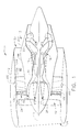
- FIG. 1 is a schematic illustration of an exemplary gas turbine engine assembly 10 having a longitudinal axis 11.
- Gas turbine engine assembly 10 includes a fan assembly 12, and a core gas turbine engine 13.
- Core gas turbine engine includes a high pressure compressor 14, a combustor 16, and a high pressure turbine 18.
- gas turbine engine assembly 10 may also include a low pressure turbine 20.
- Fan assembly 12 includes an array of fan blades 24 extending radially outward from a rotor disk 26.
- Engine 10 has an intake side 28 and an exhaust side 30.
- Gas turbine engine assembly 10 also includes a plurality of bearing assemblies (not shown in Figure 1) that are utilized to provide rotational and axial support to fan assembly 12, compressor 14, high pressure turbine 18 and low pressure turbine 20, for example.
- Gas turbine engine assembly 10 also includes a bypass duct 40 that is utilized to bypass a second portion 52 of the airflow discharged from fan assembly 12 around core gas turbine engine 13. More specifically, bypass duct 40 extends between an inner wall 201 of a fan casing or shroud 42 and an outer wall 203 of splitter 44.
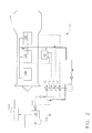
- FIG 2 is a simplified schematic illustration of an exemplary lubrication oil supply and scavenge system 100 that may be utilized with a gas turbine engine assembly 10 (shown in Figure 1).
- system 100 includes an oil supply source 120, one or more pumps 110 and 112 which circulate the oil to bearings 104, 106, 108 and to the gearbox 60 and return the hot oil to the oil supply source via heat exchanger assembly 130 which cools it to a lower temperature.
- heat exchanger assembly 130 includes an inlet valve 132, and outlet valve 134, and a bypass valve 136 that may be either manually or electrically operated.
- heat exchanger assembly 130 is a conformal aircooled heat exchanger that is positioned within bypass duct 40.
- heat exchanger assembly 130 may be utilized in a wide variety of applications on or off the engine. More specifically, although heat exchanger assembly 130 is described herein to cool oil for engine bearings, it may alternatively or simultaneously cool other fluids. For example, it may cool a fluid used to extract heat from generators or actuators used on the engine. It may also be used to cool fluids which extract heat from electronic apparatus such as engine controls.
- heat exchanger assembly 130 may also cool an apparatus that is mounted on the airframe, and not part of the engine.
- the heat exchanger may be mounted remotely from the gas turbine engine, for example on an external surface of the aircraft.
- heat exchanger assembly 130 may be utilized in a wide variety of other applications to either cool or heat various fluids channeled therethrough.
- heat exchanger 130 is coupled to inner wall 201 of fan shroud 42 between fan assembly 12 and a fan strut 150.
- heat exchanger assembly 130 is coupled to inner wall 201, upstream from fan assembly 12, (shown in Figure 1) such that air channeled into intake side 28 is first channeled through heat exchanger assembly 130 prior to being supplied to fan assembly 12 to facilitate reducing the operating temperature of the fluid channeled through heat exchanger assembly 130.
- heat exchanger assembly 130 may be positioned anywhere along the axial length of the bypass duct 40 either on the inside of the fan casing 42 or the outside of the splitter 44. In the exemplary embodiment, efficiency is increased when heat exchanger assembly 130 is positioned nearer the engine intake side 28, which is cooler than the engine exhaust side 30.
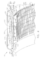
- FIG 3 is a perspective view of heat exchanger assembly 130 and Figure 4 is a cross-sectional view of heat exchanger assembly 130 taken through line 4 - 4 shown in Figure 3.
- heat exchanger assembly 130 is bent such that heat exchanger assembly 130 has a circumferential and axial profile that is substantially similar to the circumferential and axial profile of at least a portion of the bypass duct. More specifically, as shown in Figure 1, heat exchanger assembly 130 is bent such that is has a circumferential and axial profile that is conforming to the circumferential and axial profile of the inner surface 201 of fan shroud 42 at the location where it is mounted, as shown in Figures 1 and 8.
- heat exchanger 130 has a substantially arcuate shape such heat exchanger assembly 130 may be placed proximate to an inner surface 201 of fan shroud 42 in alternate locations including those shown in Figures 1 and 8. Moreover, heat exchanger 130 may also be bent such that is has a circumferential and axial profile that is substantially similar to the circumferential and axial profile of the outer surface of splitter 44 as shown in Figure 9.
- the heat exchanger assembly 130 covers substantially all (about 320°) of the circumference.
- the heat exchanger may be formed by several segments, which are mounted end-to-end to cover the same circumferential length.
- heat exchanger assembly 130 includes a manifold portion 202 having a first end 210 and an opposite second end 212.
- Manifold portion 202 also includes a radially inner surface 220, a radially outer surface 222, an upstream wall 226, and an opposite downstream wall 224 such that manifold portion 202 has a substantially rectangular cross-sectional profile.
- Manifold portion 202 also plurality of cooling fins 230 extending radially inward from radially inner surface 220.
- the cooling fins 130 may extend either radially inward as shown in Figures 3 and 4, or may extend radially outward, or may include fins that extend both radially inward and radially outward from manifold portion 202.
- the cooling fins 130 may extend either radially inward as shown in Figures 3 and 4, or may extend radially outward, or may include fins that extend both radially inward and radially outward from manifold portion 202.
- Manifold portion 202 also encloses at least one opening 232 extending lengthwise therethrough that is selectively sized to receive fluid to be cooled therethrough.
- manifold portion 202 includes a plurality of openings 232 extending therethrough.
- manifold portion 202 may include a quantity greater than or less than eight openings 232 based on the cooling reduction desired.
- openings 232 have a substantially rectangular cross-sectional profile.
- openings 232 have a cross-sectional profile that is not rectangular such as for example, circular.
- these openings are parallel channels that may all carry the same fluid, or they may be segregated into multiple groups where each group carries a different cooling fluid used for different cooling purposes. For example, one group may carry lubrication fluid for the bearings, and another group might carry a separate cooling fluid for electronic apparatus on the engine.
- cooling fins 230 extend along the width of the manifold between the lateral (upstream and downstream) edges of the manifold and are spaced around the exchanger. As installed in the turbine engine, the fins extend axially along centerline axis 11 in parallel with the airflow direction and are arranged radially around an inside or outside surface of gas turbine engine 10. In the exemplary embodiment, cooling fins 230 are coupled to manifold portion 202 such that each of the cooling fins 230 is substantially perpendicular to openings 232 and such that the direction of the fluid channeled through openings 232 is approximately perpendicular to the direction of airflow channeled through cooling fins 230.
- cooling fins 230 are aligned substantially parallel with centerline axis 11 such that the airflow channeled into or around fan intake 28 is first channeled through a plurality of openings or channels 236 defined between adjacent cooling fins 230.
- Figure 4 illustrates each cooling fin 230 as including a plurality of cooling fin segments 238, it should be realized that each cooling fin may be formed as a unitary cooling fin, i.e. does not include segments 238, without effecting the scope of the invention described herein.
- manifold portion 202 is formed utilizing an extrusion process.
- An integral fin forming process for example, is then conducted to form the cooling fins 230.
- cooling fins 230 may be attached to manifold portion 202 utilizing a welding or brazing procedure, for example.
- manifold portion 202 and cooling fins 230 are fabricated from a metallic material such as aluminum, for example.
- the upstream-to-downstream width of the manifold 202 may be assembled from several narrower extrusions each containing a subset of the plurality of channels 232 and a subset of the plurality of fins 238. These sections may be connected by welding, brazing, interlocking or other mechanical attachment.
- heat exchanger assembly 130 also includes one or a plurality of inlet connections 240 that are each coupled to manifold portion first end 210 and one or a plurality of outlet connections 242 that are each coupled to manifold portion second end 212.
- at least one inlet connection 240 is coupled downstream from valve 132 (shown in Figure 2) and at least one outlet connection 242 is coupled upstream from valve 134 (shown in Figure 2) such that valves 132 and 134 may be operated to channel lubrication fluid from system 100 through heat exchanger assembly 130 during desired operating conditions.
- a bypass valve 136 may be utilized to bypass the lubrication fluid around heat exchanger assembly 130.
- the heat exchanger can be configured to have a plurality of fluid circuits, each with an inlet connection and an outlet connection. These circuits can each have a separate and distinct purpose and carry non-mixing fluids, which are used for cooling different apparatus.
- manifold portion 202 includes a first attachment portion 244 that is coupled to downstream wall 224 and a second attachment portion 246 that is coupled to upstream wall 226. More specifically, first and second attachment portions 244 and 246 each have width 248 that is less than a width 250 of manifold portion 202 such that a first shoulder or recess 252 is defined radially inward from first attachment portion 244 and a second shoulder or recess 254 is defined radially inward from second attachment portion 246.
- attachment portions 244 and 246 are each fabricated from the same metallic material as manifold portion 202 and formed unitarily with manifold portion 202 utilizing an extrusion process, for example.
- attachment portions 244 and 246 are formed as separate components that are attached to manifold portion 202 utilizing a welding or brazing procedure, for example.
- heat exchanger assembly 130 is positioned within gas turbine engine assembly 10 that the inner wall 201 of fan shroud 42 is positioned within respective recesses 252 and 254 and such that the inner surface of inner wall 201 is flush with the surface of manifold 202 at the base of the fins 230 to facilitate reducing or eliminating turbulence caused by heat exchanger assembly 130. More specifically, heat exchanger assembly 130 is coupled within gas turbine engine assembly 10 such that only the cooling fins 230 extend into fan duct 40. As such, the inner wall 201 of fan shroud 42 is utilized to substantially cover manifold portion 202 such that cooling airflow is channeled only through cooling fins 230.
- a radially outer plate 270 that is fabricated with gas turbine engine 10, is utilized to mount heat exchanger assembly 130. More specifically, the outer plate 270 may be coupled to or formed integrally as part of fan shroud 42.
- heat exchanger assembly 130 also includes a plurality of standoffs 274 that extend between manifold portion 202 and outer plate 270 to facilitate maintaining manifold portion 202 in a substantially fixed position within a recess 272 that is formed in outer plate 270, and an insulating material 276 that is positioned between standoffs 274 to facilitate reducing heat transfer between manifold portion 202 and an exterior surface of gas turbine engine 10.
- insulating material 276 is a ceramic insulating blanket.
- standoffs 274 are not attached to heat exchanger assembly 130, rather standoffs 274 are utilized to set the height of heat exchanger assembly 130 and thus control its "flushness" with the inner surface of inner wall 201.
- radially outer plate 270 with preassembled standoffs 274 positioned radially around outer plate 270 are initially attached to gas turbine engine 10. Insulating material 276 is then deposited between standoffs 274, and radially outer plate 270. It is then secured to outer plate 270 utilizing an adhesive, for example.
- Heat exchanger 130 is pre-bent or shaped such that heat exchanger 130 has a profile that substantially conforms to a profile of fan casing inner surface 201 or fan casing outer surface 203. Heat exchanger assembly 130 is then coupled to gas turbine engine assembly 10 such that such that the inner surface of inner wall 201 is flush with the surface of manifold 202 at the base of the fins 230 as discussed above.
- hot lubrication fluid is channeled from the gas turbine engine 10 through the plurality of openings 232 of heat exchanger 130 and discharged at a substantially cooler temperature to reservoir 120 (shown in Figure 2).
- the lubrication fluid is channeled in a substantially circumferential orientation within or around gas turbine engine 10.
- cooling airflow supplied into or around fan intake 28 is channeled through cooling fins 230 to facilitate reducing an operational temperature of the lubrication fluid channeled through heat exchanger assembly 130.
- the relatively warm lubrication fluid is channeled through openings 232 wherein the relatively warm fluid transfers its heat to a conductive surface, i.e. an inner surface 220 of manifold 202 and thus cooling fins 230.
- the relatively cooler air passing through or around intake 28 is channeled across and/or through cooling fins 230 wherein the heat is transferred from cooling fins 230 to the airflow through the bypass duct 40.
- the cooling air channeled into fan intake 28 facilitates reducing a temperature of the cooling fins 230, thus reducing a temperature of heat exchanger 130 and therefore a temperature of the fluid channeled through manifold portion 202.
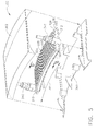
- FIG 5 is a perspective view of another exemplary conformal heat exchanger assembly that may be utilized with gas turbine engine 10 (shown in Figure 1).
- Figure 6 is a cross -sectional view of heat exchanger assembly 300 taken through line 6 - 6 shown in Figure 5.
- Figure 7 is a perspective view of heat exchanger assembly 300 coupled to gas turbine engine 10.
- heat exchanger 300 may be utilized in conjunction with heat exchanger 130 to provide additional cooling or independently for cooling a different apparatus.
- heat exchanger 300 may be utilized in lieu of heat exchanger 130 when reduced cooling is required.
- heat exchanger assembly 300 has a substantially arcuate shape such heat exchanger assembly 300 may be placed proximate to inner surface 201 or outer surface 203 of fan shroud 42 as shown respectively in Figures 8 and 9.
- heat exchanger assembly 300 has a length 301 that is substantially less than a length of heat exchanger assembly 130. More specifically, heat exchanger assembly 300 does not substantially circumscribe fan shroud 42, rather heat exchanger 300 has a length 301 that is predetermined based on the cooling capacity required to reduce the operational temperature of the lubrication fluid channeled therethrough whether heat exchanger 300 is used in conjunction with or separately from heat exchanger assembly 130. Additional segments similar to 300 may be located at other places around the circumference, and plumbed such that they are combined when additional cooling is necessary.
- heat exchanger 300 includes a first end 310 and an opposite second end 312.
- Heat exchanger 300 also includes a radially inner surface 320, a radially outer surface 322, a first upstream side 324, and an opposite downstream second side 326 such that heat exchanger 300 has a substantially rectangular cross-sectional profile.
- Heat exchanger 300 also plurality of cooling fins 330 extending radially inward from radially inner surface 320.
- heat exchanger 300 also includes a plurality of cooling fins 330 that extend radially outward from radially outer surface 322.
- Heat exchanger 300 also includes a plurality of openings 332 extending lengthwise therethrough that are each selectively sized to receive fluid to be cooled therethrough.
- heat exchanger 300 includes eight openings 332 extending therethrough.
- heat exchanger 300 may include a quantity greater than or less than eight openings 332 based on the cooling reduction desired.
- openings 332 have a substantially rectangular cross-sectional profile.
- openings 332 have a cross-sectional profile that is not rectangular such as for example, circular.
- the plurality of channels may be combined, or may be used in separate and independent cooling circuits.
- cooling fins 330 extend along the width of the manifold between the lateral edges of the manifold and are spaced around the exchanger. As installed in the turbine engine, the fins extend axially along centerline axis I 1 and are arranged radially around an inside surface of gas turbine engine 10. Moreover, cooling fins 330 are coupled to heat exchanger 300 such that each of the cooling fins 330 is substantially perpendicular to openings 332 and such that the direction of the fluid channeled through openings 332 is approximately perpendicular to the direction of airflow channeled through cooling fins 330.
- cooling fins 330 are aligned substantially parallel with centerline axis 11 such that the airflow channeled into or around fan inlet 28 is channeled through a plurality of openings or channels 334 defined between adjacent cooling fins 330.
- Figures 5 and 6 illustrates each cooling fin 330 as being a substantially unitary cooling fin, it should be realized that each cooling fin 330 may be segmented to include a plurality of cooling fin segments 338 without effecting the scope of the invention described herein.
- manifold portion 322 is formed utilizing an extrusion process.
- An integral fin forming process for example, is then conducted to form the cooling fins 330.
- cooling fins 330 may be attached to manifold portion 322 utilizing a welding or brazing procedure, for example.
- manifold portion 322 and cooling fins 330 are fabricated from a metallic material such as aluminum, for example.
- heat exchanger 300 also includes one or a plurality of inlet connection 340 that are each coupled to first end 310 and one or a plurality of outlet connections 342 that are each coupled to second end 312.
- inlet connection 340 is coupled to downstream from valve 132 (shown in Figure 2) and outlet connection 342 is coupled upstream from valve 1 34 (shown in Figure 2) such that valves 132 and 134 may be operated to channel lubrication fluid from system 100 through heat exchanger assembly 300 during desired operating conditions.
- a bypass valve 136 may be utilized to bypass the lubrication fluid around heat exchanger assembly 300.
- heat exchanger assembly 300 also includes a radially inner plate 360 that also forms the inner surface 201 of the fan casing and a radially outer plate 362 that define a cavity 364 therebetween.
- heat exchanger 300 is coupled between plates 360 and 362, respectively within cavity 364.
- radially inner plate 360 includes at least one inlet opening 366 that is utilized to channel airflow into cavity 364 and thus across heat exchanger 300.
- Radially inner plate also includes at least one outlet opening 368 that is positioned downstream from inlet opening 366 such that airflow discharged from cavity 364 is exhausted from the gas turbine engine assembly 10.
- heat exchanger 300 is recessed beneath radially inner plate 360.
- radially inner plate 360 facilitates channeling a portion of the airflow across heat exchanger 300.
- lubrication fluid is channeled from the gas turbine engine 10 through the plurality of openings 332 defined through heat exchanger 300 and discharged to reservoir 120 (shown in Figure 2). Specifically, the lubrication fluid is channeled in a substantially circumferential orientation within gas turbine engine 10. Simultaneously, cooling airflow supplied through or around fan inlet 28 is channeled through opening 366, across the heat exchanger cooling fins 330, and exhausted through opening 368 to fan assembly 12 to facilitate reducing an operational temperature of the lubrication fluid channeled through heat exchanger assembly 300.
- the relatively warm lubrication fluid is channeled through openings 332 wherein the relatively warm fluid transfers its heat to a conductive surface, i.e. an upper and/or lower surface of heat exchanger 300 and thus cooling fins 330.
- the relatively cooler air supplied via inlet 28 is channeled across and/or through cooling fins 330 wherein the heat is transferred from cooling fins 330 to the airflow channeled through cavity 364.
- the heated airflow is then discharged from cavity 364 via opening 368 aftward to fan assembly 12.
- each heat exchanger assembly includes a heat exchanger having a substantially rectangular cross-sectional profile and a plurality of cooling openings extending therethrough.
- the heat exchanger also includes a plurality of cooling fins that are coupled to the radially inner surface of the heat exchanger and may also be coupled to the radially outer surface of the heat exchanger.
- the heat exchanger may be fabricated utilizing an extruded aluminum material that intersects the airflow path and has a relatively small cross-sectional profile to facilitate a minimizing pressure loss within the bypass duct that may be attributed to the heat exchanger assembly.
- the fin profiles are between approximately 0.010 and approximately 0.025 inches thick with a fin length between approximately 0.4 and 0.5 inches.
- the heat exchanger fins protrude into the airflow stream approximately 0.4 to 0.5 inches, but that is a variable depending on the specific engine.
- a known "brick" type heat exchanger is installed on a similar engine it resulted in a pressure drop loss of approximately 0.35% SFC.
- the conformal heat exchanger described herein resulted in a pressure drop of approximately 0.06% SFC.
- the conformal heat exchanger described herein is approximately 4 times larger in heat transfer capacity than the known "brick" heat exchanger. Therefore, on an equal heat transfer basis, the "conformal" cooler had an SFC impact of approximately 0.015%.
- each heat exchanger assembly may be utilized in a wide variety of gas turbine engines and positioned within a wide variety of locations within the gas turbine engine.
- the heat exchanger assemblies described herein may also be coupled to the radially outer wall of the splitter within the bypass duct, or to an external surface of the fan shroud if desired. Where practical, they can be mounted anywhere there is an airflow which can provide cooling.
Applications Claiming Priority (1)
| Application Number | Priority Date | Filing Date | Title |
|---|---|---|---|
| US11/550,894 US8387362B2 (en) | 2006-10-19 | 2006-10-19 | Method and apparatus for operating gas turbine engine heat exchangers |
Publications (2)
| Publication Number | Publication Date |
|---|---|
| EP1916399A2 true EP1916399A2 (de) | 2008-04-30 |
| EP1916399A3 EP1916399A3 (de) | 2011-09-28 |
Family
ID=39009619
Family Applications (1)
| Application Number | Title | Priority Date | Filing Date |
|---|---|---|---|
| EP07118642A Withdrawn EP1916399A3 (de) | 2006-10-19 | 2007-10-17 | Wärmetauscheranordnung für ein Gasturbinentriebwerk |
Country Status (4)
| Country | Link |
|---|---|
| US (1) | US8387362B2 (de) |
| EP (1) | EP1916399A3 (de) |
| JP (2) | JP2008144752A (de) |
| CN (1) | CN101178027A (de) |
Cited By (44)
| Publication number | Priority date | Publication date | Assignee | Title |
|---|---|---|---|---|
| EP2339123A1 (de) | 2009-12-23 | 2011-06-29 | Techspace Aero S.A. | Innere Seite des Mantels des Sekundärstromes eines Turbostrahltriebwerkes und Verfahren zur Montage eines solchen Mantels |
| EP2472067A1 (de) * | 2010-12-31 | 2012-07-04 | Techspace Aero S.A. | Einbau eines Oberflächenwärmetauschers mit reguliertem Luftdurchsatz in einen Flugzeugmotor |
| DE102011106961A1 (de) * | 2011-07-08 | 2013-01-10 | Rolls-Royce Deutschland Ltd & Co Kg | Fluggasturbinentriebwerk mit Kühlelementen am Kerntriebwerksgehäuse |
| DE102011106965A1 (de) * | 2011-07-08 | 2013-01-10 | Rolls-Royce Deutschland Ltd & Co Kg | Fluggasturbinentriebwerk mit Wärmetauscher im Kerntriebwerksgehäuse |
| EP2006493A3 (de) * | 2007-06-20 | 2013-04-10 | United Technologies Corporation | Wärmeverwaltungssystem für Flugzeugkombinationsmotoren |
| WO2013095731A3 (en) * | 2011-12-20 | 2013-08-15 | Unison Industries, Llc | Method for forming a heat exchanger and portions thereof |
| FR2989108A1 (fr) * | 2012-04-05 | 2013-10-11 | Snecma | Partie de stator comportant une aube de stator et une structure de conduction thermique |
| FR2990001A1 (fr) * | 2012-04-27 | 2013-11-01 | Snecma | Assemblage d'un echangeur thermique au sein d'un carter intermediaire de turboreacteur |
| WO2014018198A1 (en) * | 2012-07-27 | 2014-01-30 | General Electric Company | Air-cooled engine surface cooler |
| WO2014022046A3 (en) * | 2012-07-30 | 2014-03-20 | General Electric Company | Heat exchanger for an intercooler and water extraction apparatus |
| EP2762685A1 (de) * | 2013-01-30 | 2014-08-06 | General Electric Company | In einem Gasturbinenmotor eingebauter Wärmetauscher |
| EP2336504A3 (de) * | 2009-12-09 | 2014-08-20 | Rolls-Royce plc | Ölkühler |
| FR3003024A1 (fr) * | 2013-03-11 | 2014-09-12 | Snecma | Echangeur de chaleur d'une turbomachine |
| WO2015042398A1 (en) * | 2013-09-20 | 2015-03-26 | General Electric | Aviation bypass valve including a shape memory alloy material |
| EP2894323A1 (de) * | 2014-01-13 | 2015-07-15 | United Technologies Corporation | Luftumlenker mit doppelfunktion und fandüse mit variablem querschnitt |
| WO2015108674A1 (en) | 2014-01-15 | 2015-07-23 | United Technologies Corporation | Cooling systems for gas turbine engines |
| FR3028020A1 (fr) * | 2014-10-29 | 2016-05-06 | Snecma | Panneau d'echange thermique et de reduction de bruit ameliore pour une turbomachine |
| FR3028019A1 (fr) * | 2014-10-29 | 2016-05-06 | Snecma | Panneau d'echange thermique et de reduction de bruit pour une turbomachine |
| DE102015203218A1 (de) * | 2015-02-23 | 2016-08-25 | Rolls-Royce Deutschland Ltd & Co Kg | Gasturbinentriebwerk mit Ölkühler in der Triebwerksverkleidung |
| EP3070317A1 (de) * | 2015-03-20 | 2016-09-21 | Techspace Aero S.A. | Kühlung für turbomaschine durch verdampfung |
| EP3168425A1 (de) * | 2015-11-10 | 2017-05-17 | General Electric Company | Verfahren und system zum kühlen von flugzeugtriebwerkflüssigkeit |
| WO2018017003A1 (en) * | 2016-07-19 | 2018-01-25 | Volvo Construction Equipment Ab | A heat exchanger and a working machine |
| WO2018009259A3 (en) * | 2016-05-11 | 2018-03-01 | General Electric Company | Gas turbine engine having a surface cooler with ogv oriented fin angles |
| EP3290846A1 (de) * | 2016-08-31 | 2018-03-07 | Unison Industries LLC | Motorwärmetauscher und verfahren zur herstellung |
| EP3401629A1 (de) * | 2017-05-11 | 2018-11-14 | Unison Industries LLC | Wärmetauscher |
| US10208621B2 (en) | 2015-12-07 | 2019-02-19 | General Electric Company | Surface cooler and an associated method thereof |
| US10393147B2 (en) | 2015-07-23 | 2019-08-27 | Unison Industries, Llc | Fan casing assemblies and method of mounting a cooler to a fan casing |
| EP3534101A1 (de) * | 2018-03-01 | 2019-09-04 | Rolls-Royce plc | Wärmetauscher |
| FR3087889A1 (fr) | 2018-10-31 | 2020-05-01 | Safran Aircraft Engines | Dispositif et procede de surveillance de duree de vie d'un equipement hydraulique d'un aeronef |
| FR3087888A1 (fr) | 2018-10-31 | 2020-05-01 | Safran Aircraft Engines | Dispositif et procede de surveillance de duree de vie d'un equipement hydraulique d'un aeronef |
| FR3087887A1 (fr) | 2018-10-31 | 2020-05-01 | Safran Aircraft Engines | Dispositif et procede de surveillance de duree de vie d'un equipement hydraulique d'un aeronef |
| WO2020234525A2 (fr) | 2019-05-20 | 2020-11-26 | Safran | Systeme d'echange de chaleur optimise |
| WO2020234524A1 (fr) | 2019-05-20 | 2020-11-26 | Safran | Systeme d'echange de chaleur optimise de turbomachine |
| GB2599692A (en) * | 2020-10-09 | 2022-04-13 | Rolls Royce Plc | A heat exchanger |
| GB2599688A (en) * | 2020-10-09 | 2022-04-13 | Rolls Royce Plc | An improved turbofan gas turbine engine |
| EP3981973A1 (de) * | 2020-10-09 | 2022-04-13 | Rolls-Royce plc | Flugzeug |
| GB2599687A (en) * | 2020-10-09 | 2022-04-13 | Rolls Royce Plc | An improved turbofan gas turbine engine |
| EP3981972A1 (de) * | 2020-10-09 | 2022-04-13 | Rolls-Royce plc | Wärmetauscher |
| US20220112840A1 (en) * | 2020-10-09 | 2022-04-14 | Rolls-Royce Plc | Heat exchanger |
| WO2022074339A1 (fr) * | 2020-10-08 | 2022-04-14 | Safran | Échangeur de chaleur en contre-courant pour turbomachine, turbomachine et procédé de fabrication de l'échangeur |
| EP3988770A1 (de) * | 2020-10-09 | 2022-04-27 | Rolls-Royce plc | Verbessertes mantelstrom-gasturbinentriebwerk |
| WO2022173416A1 (en) * | 2021-02-09 | 2022-08-18 | Raytheon Technologies Corporation | Compact two-phase heat exchanger |
| US11466700B2 (en) | 2017-02-28 | 2022-10-11 | Unison Industries, Llc | Fan casing and mount bracket for oil cooler |
| RU2803373C2 (ru) * | 2019-04-17 | 2023-09-12 | Сафран Эркрафт Энджинз | Теплообменник воздух второго контура/текучая среда, способ его изготовления и двухконтурный газотурбинный двигатель, оснащенный таким теплообменником |
Families Citing this family (111)
| Publication number | Priority date | Publication date | Assignee | Title |
|---|---|---|---|---|
| US8234873B2 (en) * | 2008-08-28 | 2012-08-07 | Woodward, Inc. | Multi passage fuel manifold and methods of construction |
| FR2946089B1 (fr) * | 2009-05-27 | 2012-05-04 | Airbus France | Dispositif de refroidissement de fluides pour propulseur a turbomachine |
| US8307662B2 (en) * | 2009-10-15 | 2012-11-13 | General Electric Company | Gas turbine engine temperature modulated cooling flow |
| IL201610B (en) * | 2009-10-18 | 2021-10-31 | Israel Hirshberg | Use of hot gases and facilities |
| US8499544B2 (en) * | 2009-11-17 | 2013-08-06 | General Electric Company | Turbogenerator with cooling system |
| EP2336525B1 (de) * | 2009-12-21 | 2015-08-26 | Techspace Aero S.A. | Einbau eines Luft-Flüssigkeits-Wärmetauschers in einen Motor |
| US20110146944A1 (en) * | 2009-12-22 | 2011-06-23 | John Hand | Heat Exchanger Mounting Assembly |
| US8510945B2 (en) * | 2009-12-22 | 2013-08-20 | Unison Industries, Llc | Method of mounting a heat exchanger in a gas turbine engine assembly |
| US9467021B2 (en) * | 2010-02-16 | 2016-10-11 | Sine Waves, Inc. | Engine and induction generator |
| US8770269B2 (en) | 2010-06-11 | 2014-07-08 | Hs Marston Aerospace Ltd. | Three phase fin surface cooler |
| US8544531B2 (en) * | 2010-06-11 | 2013-10-01 | Hs Marston Aerospace Ltd. | Surface cooler with noise reduction |
| US20130011244A1 (en) * | 2010-07-29 | 2013-01-10 | General Electric Company | Reconfigurable heat transfer system for gas turbine inlet |
| US8784047B2 (en) * | 2010-11-04 | 2014-07-22 | Hamilton Sundstrand Corporation | Gas turbine engine heat exchanger with tapered fins |
| US9051943B2 (en) | 2010-11-04 | 2015-06-09 | Hamilton Sundstrand Corporation | Gas turbine engine heat exchanger fins with periodic gaps |
| US8961114B2 (en) * | 2010-11-22 | 2015-02-24 | General Electric Company | Integrated variable geometry flow restrictor and heat exchanger |
| US20120308369A1 (en) * | 2011-05-31 | 2012-12-06 | Mra Systems, Inc. | Laminate thermal insulation blanket for aircraft applications and process therefor |
| US9045998B2 (en) | 2011-12-12 | 2015-06-02 | Honeywell International Inc. | System for directing air flow to a plurality of plena |
| US9243563B2 (en) * | 2012-01-25 | 2016-01-26 | Honeywell International Inc. | Gas turbine engine in-board cooled cooling air system |
| US9267434B2 (en) * | 2012-01-29 | 2016-02-23 | United Technologies Corporation | Heat exchanger |
| US9200570B2 (en) * | 2012-02-24 | 2015-12-01 | Pratt & Whitney Canada Corp. | Air-cooled oil cooler for turbofan engine |
| US9267390B2 (en) | 2012-03-22 | 2016-02-23 | Honeywell International Inc. | Bi-metallic actuator for selectively controlling air flow between plena in a gas turbine engine |
| CN103362650B (zh) * | 2012-04-01 | 2016-03-30 | 中航商用航空发动机有限责任公司 | 航空发动机的冷却系统及其方法 |
| FR2989734B1 (fr) * | 2012-04-24 | 2014-04-18 | Snecma | Turboreacteur incorporant des generateurs thermoelectriques |
| US9879600B2 (en) | 2012-04-30 | 2018-01-30 | General Electric Company | Turbine component cooling system |
| US9945252B2 (en) * | 2012-07-05 | 2018-04-17 | United Technologies Corporation | Gas turbine engine oil tank with integrated packaging configuration |
| US20140044525A1 (en) * | 2012-08-07 | 2014-02-13 | Unison Industries, Llc | Gas turbine engine heat exchangers and methods of assembling the same |
| US9765694B2 (en) * | 2012-08-07 | 2017-09-19 | Unison Industries, Llc | Gas turbine engine heat exchangers and methods of assembling the same |
| US9714610B2 (en) * | 2012-10-04 | 2017-07-25 | United Technologies Corporation | Low profile compressor bleed air-oil coolers |
| WO2014130103A2 (en) | 2013-02-20 | 2014-08-28 | United Technologies Corporation | Integrated heat exchangers for low fan pressure ratio geared turbofan |
| EP2971672B1 (de) * | 2013-03-15 | 2018-09-26 | United Technologies Corporation | Gasturbinenmotor mit öltank mit luft-öl-kühler |
| JP2016531032A (ja) * | 2013-06-03 | 2016-10-06 | ユニゾン・インダストリーズ,エルエルシー | 航空機用共形表面熱交換器 |
| US10100740B2 (en) | 2013-06-14 | 2018-10-16 | United Technologies Corporation | Curved plate/fin heater exchanger |
| JP5442916B1 (ja) | 2013-06-26 | 2014-03-19 | 住友精密工業株式会社 | 航空機用エンジンの熱交換器 |
| CA2924679C (en) | 2013-09-22 | 2018-07-17 | Unison Industries, Llc | Dual seated by-pass valve for surface coolers |
| WO2015047533A1 (en) * | 2013-09-24 | 2015-04-02 | United Technologies Corporation | Bypass duct heat exchanger placement |
| US11162424B2 (en) | 2013-10-11 | 2021-11-02 | Reaction Engines Ltd | Heat exchangers |
| US9677474B2 (en) | 2013-11-18 | 2017-06-13 | Unison Industries, Llc | Surface cooler support mechanism |
| US10443429B2 (en) | 2014-02-13 | 2019-10-15 | United Technologies Corporation | Gas turbine nacelle ventilation manifold having a circumferential varying cross-sectional area |
| EP2910887B1 (de) * | 2014-02-21 | 2019-06-26 | Rolls-Royce Corporation | Mikrokanalwärmetauscher für gasturbinenzwischenkühlung und kondensation sowie korrespondierende methode |
| US10006369B2 (en) | 2014-06-30 | 2018-06-26 | General Electric Company | Method and system for radial tubular duct heat exchangers |
| US9777963B2 (en) * | 2014-06-30 | 2017-10-03 | General Electric Company | Method and system for radial tubular heat exchangers |
| JP6507535B2 (ja) | 2014-09-10 | 2019-05-08 | 株式会社Ihi | 低バイパス比ターボファンエンジンのためのバイパスダクトフェアリングおよびそれを備えたターボファンエンジン |
| US9593594B2 (en) | 2014-09-30 | 2017-03-14 | General Electric Company | Method and apparatus for decongealing a lubricating fluid in a heat exchanger apparatus |
| CN105525992B (zh) * | 2014-10-21 | 2020-04-14 | 联合工艺公司 | 具有增材制造整流罩的增材制造管道式换热器系统 |
| WO2016063312A1 (ja) * | 2014-10-21 | 2016-04-28 | 住友精密工業株式会社 | 航空機エンジン用の熱交換器 |
| JP5844503B1 (ja) * | 2014-10-21 | 2016-01-20 | 住友精密工業株式会社 | 航空機エンジン用の熱交換器 |
| JP6174655B2 (ja) | 2014-10-21 | 2017-08-02 | ユナイテッド テクノロジーズ コーポレイションUnited Technologies Corporation | ガスタービンエンジン用のダクテッド熱交換器システム、およびガスタービンエンジン用の熱交換器の製造方法 |
| US9810150B2 (en) * | 2014-10-21 | 2017-11-07 | United Technologies Corporation | Heat exchanger assembly |
| US9903274B2 (en) | 2014-11-07 | 2018-02-27 | General Electric Company | Variable geometry heat exchanger apparatus |
| FR3029240B1 (fr) * | 2014-11-27 | 2016-11-18 | Snecma | Agencements a entree d'air et piege de corps etrangers dans un ensemble propulsif d'aeronef |
| US10907500B2 (en) * | 2015-02-06 | 2021-02-02 | Raytheon Technologies Corporation | Heat exchanger system with spatially varied additively manufactured heat transfer surfaces |
| US9835380B2 (en) | 2015-03-13 | 2017-12-05 | General Electric Company | Tube in cross-flow conduit heat exchanger |
| US9982630B2 (en) | 2015-05-26 | 2018-05-29 | Pratt & Whitney Canada Corp. | Turbofan bypass air cooled oil cooler fairings |
| GB201512516D0 (en) * | 2015-07-17 | 2015-08-19 | Rolls Royce Plc | A gas turbine engine |
| US10578020B2 (en) * | 2015-07-21 | 2020-03-03 | Unison Industries, Llc | Integral oil tank heat exchanger |
| EP3130539B1 (de) | 2015-08-12 | 2020-04-08 | Rolls-Royce North American Technologies, Inc. | Wärmetauscher für ein gasturbinenmotorantriebssystem |
| US11125160B2 (en) * | 2015-12-28 | 2021-09-21 | General Electric Company | Method and system for combination heat exchanger |
| US10697371B2 (en) * | 2015-12-28 | 2020-06-30 | General Electric Company | Method and system for a combined air-oil cooler and fuel-oil cooler heat exchanger |
| US10125684B2 (en) | 2015-12-29 | 2018-11-13 | Pratt & Whitney Canada Corp. | Surface cooler for aero engine |
| US11002290B2 (en) | 2016-01-08 | 2021-05-11 | General Electric Company | Heat exchanger for embedded engine applications: curvilinear plate |
| US10184400B2 (en) * | 2016-01-08 | 2019-01-22 | General Electric Company | Methods of cooling a fluid using an annular heat exchanger |
| US10344674B2 (en) | 2016-01-08 | 2019-07-09 | General Electric Company | Heat exchanger for embedded engine applications: transduct segments |
| US10126062B2 (en) | 2016-01-08 | 2018-11-13 | General Electric Company | Heat exchanger for embedded engine applications |
| FR3047270B1 (fr) * | 2016-01-29 | 2019-03-29 | Safran Aircraft Engines | Echangeur thermique surfacique et traitement acoustique |
| US10753229B2 (en) * | 2016-02-17 | 2020-08-25 | Pratt & Whitney Canada Corp | Mounting arrangement for mounting a fluid cooler to a gas turbine engine case |
| US10151247B2 (en) * | 2016-03-18 | 2018-12-11 | United Technologies Corporation | Heat exchanger suspension system with pipe-to-linkage spring rate ratio |
| US10378835B2 (en) | 2016-03-25 | 2019-08-13 | Unison Industries, Llc | Heat exchanger with non-orthogonal perforations |
| JP2017223212A (ja) * | 2016-06-16 | 2017-12-21 | 早川 秀樹 | エンジンと多目的ファンモーターターボ |
| US10443436B2 (en) * | 2016-07-01 | 2019-10-15 | General Electric Company | Modular annular heat exchanger |
| FR3054204B1 (fr) * | 2016-07-20 | 2020-01-24 | Safran Nacelles | Nacelle de turbomoteur comportant un dispositif de refroidissement |
| CN107762634B (zh) * | 2016-08-19 | 2020-09-15 | 中国航发商用航空发动机有限责任公司 | 航空发动机滑油箱及航空发动机滑油系统 |
| US11008943B2 (en) | 2016-08-31 | 2021-05-18 | Unison Industries, Llc | Fan casing assembly with cooler and method of moving |
| US20180058472A1 (en) * | 2016-08-31 | 2018-03-01 | Unison Industries, Llc | Fan casing assembly with cooler and method of moving |
| US11248526B2 (en) * | 2016-09-08 | 2022-02-15 | Unison Industries, Llc | Fan casing assembly and method |
| US11060457B2 (en) * | 2016-12-02 | 2021-07-13 | Pratt & Whitney Canada Corp. | Cooling system and method for gas turbine engine |
| US10247296B2 (en) * | 2016-12-12 | 2019-04-02 | General Electric Company | Additively manufactured gearbox with integral heat exchanger |
| FR3060057B1 (fr) * | 2016-12-14 | 2019-08-30 | Safran Aircraft Engines | Circuit fluidique dans une turbomachine |
| BR102017027998A2 (pt) * | 2017-01-13 | 2018-12-04 | Unison Industries, Llc | refrigerante de revestimento de ventilador |
| US10450957B2 (en) * | 2017-01-23 | 2019-10-22 | United Technologies Corporation | Gas turbine engine with heat pipe system |
| US20180238238A1 (en) * | 2017-02-23 | 2018-08-23 | Unison Industries, Llc | Annular surface cooler and method of forming multiple fins in a heat exchanger |
| US20180238640A1 (en) * | 2017-02-23 | 2018-08-23 | Unison Industries, Llc | Heat exchanger and methods of forming fins in a heat exchanger |
| US10514005B2 (en) * | 2017-02-24 | 2019-12-24 | Unison Industries, Llc | Turbine engine thermal seal |
| FR3065490B1 (fr) * | 2017-04-24 | 2019-07-12 | Safran Aircraft Engines | Ensemble propulsif pour aeronef comportant des echangeurs de chaleur air-liquide |
| CN108995818A (zh) * | 2017-06-07 | 2018-12-14 | 深圳光启合众科技有限公司 | 涵道风扇 |
| CN109210961B (zh) * | 2017-06-30 | 2020-02-28 | 中国航发商用航空发动机有限责任公司 | 一种用于航空发动机的液体散热器 |
| US10934936B2 (en) * | 2017-07-10 | 2021-03-02 | Rolls-Royce North American Technologies, Inc. | Cooling system in a hybrid electric propulsion gas turbine engine for cooling electrical components therein |
| EP3460377B1 (de) * | 2017-09-21 | 2020-04-29 | HS Marston Aerospace Limited | Wärmetauscherrahmen |
| US10809007B2 (en) | 2017-11-17 | 2020-10-20 | General Electric Company | Contoured wall heat exchanger |
| US10815934B2 (en) | 2017-12-21 | 2020-10-27 | Unison Industries, Llc | Integral preloaded formed bracket for attachment of heat exchangers |
| US11333447B2 (en) * | 2018-03-27 | 2022-05-17 | Hamilton Sundstrand Corporation | Additively manufactured heat exchangers and methods for making the same |
| FR3084915B1 (fr) * | 2018-08-10 | 2020-12-04 | Liebherr Aerospace Toulouse Sas | Système et procédé de refroidissement d’un fluide d’un circuit de lubrification ou de refrodissement d’un organe moteur d’un aéronef et moteur propulsif d’aéronef équipé d’un tel système de refroidissement |
| US11440665B2 (en) * | 2018-10-23 | 2022-09-13 | Airbus Operations Gmbh | Vented leading-edge assembly and method for manufacturing a vented leading-edge assembly |
| US20200180771A1 (en) * | 2018-12-06 | 2020-06-11 | General Electric Company | Thermal Management System for an Aircraft Including an Electric Propulsion Engine |
| US11300002B2 (en) | 2018-12-07 | 2022-04-12 | Pratt & Whitney Canada Corp. | Static take-off port |
| BE1027057B1 (fr) * | 2019-02-18 | 2020-09-14 | Safran Aero Boosters Sa | Échangeur de chaleur air-huile |
| US11174816B2 (en) | 2019-02-25 | 2021-11-16 | Rolls-Royce Corporation | Bypass duct conformal heat exchanger array |
| US11448131B2 (en) | 2019-04-17 | 2022-09-20 | General Electric Company | Fluid exchange apparatuses and methods of exchanging fluids between streams |
| FR3095264B1 (fr) * | 2019-04-17 | 2021-03-19 | Safran Aircraft Engines | Echangeur de chaleur air secondaire/fluide, son procédé de fabrication et turbomachine à double flux équipée de cet échangeur |
| US10927761B2 (en) | 2019-04-17 | 2021-02-23 | General Electric Company | Refreshing heat management fluid in a turbomachine |
| FR3097257B1 (fr) * | 2019-06-17 | 2021-07-02 | Sogeclair Sa | Echangeur thermique de refroidissement d'un moteur propulsif d'aéronef. |
| US11313276B2 (en) | 2019-08-01 | 2022-04-26 | Rolls-Royce Deutschland Ltd & Co Kg | Supersonic gas turbine engine |
| DE102019126123A1 (de) * | 2019-09-27 | 2021-04-01 | Rolls-Royce Deutschland Ltd & Co Kg | Wärmetauscher eines Gasturbinentriebwerkes eines Flugzeuges |
| GB2589125B (en) * | 2019-11-21 | 2022-10-19 | Gkn Aerospace Sweden Ab | Heat exchanger integration |
| US11333452B2 (en) * | 2019-12-16 | 2022-05-17 | Hamilton Sundstrand Corporation | Conformal heat exchanger passage features for improved flow distribution |
| US11378341B2 (en) | 2020-01-03 | 2022-07-05 | Raytheon Technologies Corporation | Gas turbine engine heat exchanger for annular flowpaths |
| US11448132B2 (en) | 2020-01-03 | 2022-09-20 | Raytheon Technologies Corporation | Aircraft bypass duct heat exchanger |
| US11525637B2 (en) | 2020-01-19 | 2022-12-13 | Raytheon Technologies Corporation | Aircraft heat exchanger finned plate manufacture |
| US11674758B2 (en) | 2020-01-19 | 2023-06-13 | Raytheon Technologies Corporation | Aircraft heat exchangers and plates |
| US11585273B2 (en) | 2020-01-20 | 2023-02-21 | Raytheon Technologies Corporation | Aircraft heat exchangers |
| US11585605B2 (en) | 2020-02-07 | 2023-02-21 | Raytheon Technologies Corporation | Aircraft heat exchanger panel attachment |
| US20220186664A1 (en) * | 2020-12-10 | 2022-06-16 | General Electric Company | Heat exchanger for an aircraft |
Citations (14)
| Publication number | Priority date | Publication date | Assignee | Title |
|---|---|---|---|---|
| GB528297A (en) * | 1938-07-12 | 1940-10-25 | Dewandre Co Ltd C | Improvements in or relating to heat exchange elements |
| DE1019866B (de) * | 1940-06-24 | 1957-11-21 | Bayerische Motoren Werke Ag | Anordnung des Schmierstoffkuehlers eines mit einem die Arbeitsluft foerdernden Geblaese versehenen Strahltriebwerkes |
| DE1137606B (de) * | 1960-03-01 | 1962-10-04 | Entwicklungsbau Pirna Veb | Anordnung eines Schmierstoffkuehlers fuer eine stationaere Gasstroemungsmaschine |
| US3528250A (en) * | 1969-04-16 | 1970-09-15 | Gen Motors Corp | Bypass engine with afterburning and compressor bleed air heat exchanger in bypass duct |
| US4601202A (en) * | 1983-12-27 | 1986-07-22 | General Electric Company | Gas turbine engine component cooling system |
| GB2204361A (en) * | 1987-05-07 | 1988-11-09 | Rolls Royce Plc | Deicing of a geared gas turbine engine |
| US5452573A (en) * | 1994-01-31 | 1995-09-26 | United Technologies Corporation | High pressure air source for aircraft and engine requirements |
| WO2001069064A1 (en) * | 2000-03-13 | 2001-09-20 | Allison Advanced Development Company | Cast heat exchanger system |
| US20040020213A1 (en) * | 2002-05-01 | 2004-02-05 | Jones Alan R. | Cooling Systems |
| US6698691B2 (en) * | 2001-02-15 | 2004-03-02 | Airbus France | Process for de-icing by forced circulation of a fluid, an air intake cowling of a reaction motor and device for practicing the same |
| US20050150970A1 (en) * | 2004-01-13 | 2005-07-14 | Snecma Moteurs | Cooling system for hot parts of an aircraft engine, and aircraft engine equipped with such a cooling system |
| US20050268612A1 (en) * | 2004-04-24 | 2005-12-08 | Rolls-Royce Plc | Engine |
| US20060042225A1 (en) * | 2004-08-27 | 2006-03-02 | Pratt & Whitney Canada Corp. | Bypass duct fluid cooler |
| EP1898069A2 (de) * | 2006-08-29 | 2008-03-12 | Pratt & Whitney Canada Corp. | Im Turbofan-Bypasskanal luftgekühlte Fluidkühlungsanlage |
Family Cites Families (19)
| Publication number | Priority date | Publication date | Assignee | Title |
|---|---|---|---|---|
| US4120150A (en) * | 1977-05-17 | 1978-10-17 | The United States Of America As Represented By The Secretary Of The Air Force | Compact fuel-to-air heat exchanger for jet engine application |
| US4190398A (en) | 1977-06-03 | 1980-02-26 | General Electric Company | Gas turbine engine and means for cooling same |
| US4137705A (en) | 1977-07-25 | 1979-02-06 | General Electric Company | Cooling air cooler for a gas turbine engine |
| US4254618A (en) | 1977-08-18 | 1981-03-10 | General Electric Company | Cooling air cooler for a gas turbofan engine |
| US4503683A (en) | 1983-12-16 | 1985-03-12 | The Garrett Corporation | Compact cooling turbine-heat exchanger assembly |
| US5269133A (en) | 1991-06-18 | 1993-12-14 | General Electric Company | Heat exchanger for cooling a gas turbine |
| US5269135A (en) * | 1991-10-28 | 1993-12-14 | General Electric Company | Gas turbine engine fan cooled heat exchanger |
| US5392614A (en) | 1992-03-23 | 1995-02-28 | General Electric Company | Gas turbine engine cooling system |
| US5791148A (en) * | 1995-06-07 | 1998-08-11 | General Electric Company | Liner of a gas turbine engine combustor having trapped vortex cavity |
| US5918458A (en) | 1997-02-14 | 1999-07-06 | General Electric Company | System and method of providing clean filtered cooling air to a hot portion of a gas turbine engine |
| US6145296A (en) | 1998-09-25 | 2000-11-14 | Alm Development, Inc. | Gas turbine engine having counter rotating turbines and a controller for controlling the load driven by one of the turbines |
| US6460324B1 (en) | 1999-10-12 | 2002-10-08 | Alm Development, Inc. | Gas turbine engine |
| US6385987B2 (en) | 2000-02-23 | 2002-05-14 | Leslie Schlom | Heat exchanger for cooling and for a pre-cooler for turbine intake air conditioning |
| FR2844262B1 (fr) * | 2002-09-10 | 2004-10-15 | Atofina | Procede de fabrication d'acide acrylique a partir de propane, en l'absence d'oxygene moleculaire |
| GB0311663D0 (en) * | 2003-05-21 | 2003-06-25 | Rolls Royce Plc | Aeroengine intake |
| US7140174B2 (en) | 2004-09-30 | 2006-11-28 | General Electric Company | Methods and apparatus for assembling a gas turbine engine |
| US7454894B2 (en) * | 2004-12-07 | 2008-11-25 | United Technologies Corporation | Supplemental oil cooler airflow for gas turbine engine |
| US20080053060A1 (en) * | 2006-08-29 | 2008-03-06 | Pratt & Whitney Canada Corp. | Bypass lip seal |
| US7946806B2 (en) | 2007-10-10 | 2011-05-24 | United Technologies Corporation | Gas turbine engine systems and related methods involving heat exchange |
-
2006
- 2006-10-19 US US11/550,894 patent/US8387362B2/en active Active
-
2007
- 2007-10-16 JP JP2007268449A patent/JP2008144752A/ja active Pending
- 2007-10-17 EP EP07118642A patent/EP1916399A3/de not_active Withdrawn
- 2007-10-19 CN CNA2007101944871A patent/CN101178027A/zh active Pending
-
2012
- 2012-01-17 JP JP2012006666A patent/JP5336618B2/ja not_active Expired - Fee Related
Patent Citations (14)
| Publication number | Priority date | Publication date | Assignee | Title |
|---|---|---|---|---|
| GB528297A (en) * | 1938-07-12 | 1940-10-25 | Dewandre Co Ltd C | Improvements in or relating to heat exchange elements |
| DE1019866B (de) * | 1940-06-24 | 1957-11-21 | Bayerische Motoren Werke Ag | Anordnung des Schmierstoffkuehlers eines mit einem die Arbeitsluft foerdernden Geblaese versehenen Strahltriebwerkes |
| DE1137606B (de) * | 1960-03-01 | 1962-10-04 | Entwicklungsbau Pirna Veb | Anordnung eines Schmierstoffkuehlers fuer eine stationaere Gasstroemungsmaschine |
| US3528250A (en) * | 1969-04-16 | 1970-09-15 | Gen Motors Corp | Bypass engine with afterburning and compressor bleed air heat exchanger in bypass duct |
| US4601202A (en) * | 1983-12-27 | 1986-07-22 | General Electric Company | Gas turbine engine component cooling system |
| GB2204361A (en) * | 1987-05-07 | 1988-11-09 | Rolls Royce Plc | Deicing of a geared gas turbine engine |
| US5452573A (en) * | 1994-01-31 | 1995-09-26 | United Technologies Corporation | High pressure air source for aircraft and engine requirements |
| WO2001069064A1 (en) * | 2000-03-13 | 2001-09-20 | Allison Advanced Development Company | Cast heat exchanger system |
| US6698691B2 (en) * | 2001-02-15 | 2004-03-02 | Airbus France | Process for de-icing by forced circulation of a fluid, an air intake cowling of a reaction motor and device for practicing the same |
| US20040020213A1 (en) * | 2002-05-01 | 2004-02-05 | Jones Alan R. | Cooling Systems |
| US20050150970A1 (en) * | 2004-01-13 | 2005-07-14 | Snecma Moteurs | Cooling system for hot parts of an aircraft engine, and aircraft engine equipped with such a cooling system |
| US20050268612A1 (en) * | 2004-04-24 | 2005-12-08 | Rolls-Royce Plc | Engine |
| US20060042225A1 (en) * | 2004-08-27 | 2006-03-02 | Pratt & Whitney Canada Corp. | Bypass duct fluid cooler |
| EP1898069A2 (de) * | 2006-08-29 | 2008-03-12 | Pratt & Whitney Canada Corp. | Im Turbofan-Bypasskanal luftgekühlte Fluidkühlungsanlage |
Cited By (93)
| Publication number | Priority date | Publication date | Assignee | Title |
|---|---|---|---|---|
| EP2006493A3 (de) * | 2007-06-20 | 2013-04-10 | United Technologies Corporation | Wärmeverwaltungssystem für Flugzeugkombinationsmotoren |
| EP2336504A3 (de) * | 2009-12-09 | 2014-08-20 | Rolls-Royce plc | Ölkühler |
| US8601791B2 (en) | 2009-12-23 | 2013-12-10 | Techspace Aero S.A. | Integration of a surface heat exchanger to the wall of an aerodynamic flowpath by a structure of reinforcement rods |
| EP2339123A1 (de) | 2009-12-23 | 2011-06-29 | Techspace Aero S.A. | Innere Seite des Mantels des Sekundärstromes eines Turbostrahltriebwerkes und Verfahren zur Montage eines solchen Mantels |
| EP2339123B1 (de) * | 2009-12-23 | 2013-07-10 | Techspace Aero S.A. | Innere Seite des Mantels des Sekundärstromes eines Turbostrahltriebwerkes und Verfahren zur Montage eines solchen Mantels |
| EP2472067A1 (de) * | 2010-12-31 | 2012-07-04 | Techspace Aero S.A. | Einbau eines Oberflächenwärmetauschers mit reguliertem Luftdurchsatz in einen Flugzeugmotor |
| DE102011106965A1 (de) * | 2011-07-08 | 2013-01-10 | Rolls-Royce Deutschland Ltd & Co Kg | Fluggasturbinentriebwerk mit Wärmetauscher im Kerntriebwerksgehäuse |
| EP2543865A3 (de) * | 2011-07-08 | 2017-05-17 | Rolls-Royce Deutschland & Co. KG | Turbofan-Triebwerk mit Wärmetauscher im Kerntriebwerksgehäuse |
| DE102011106961A1 (de) * | 2011-07-08 | 2013-01-10 | Rolls-Royce Deutschland Ltd & Co Kg | Fluggasturbinentriebwerk mit Kühlelementen am Kerntriebwerksgehäuse |
| WO2013095731A3 (en) * | 2011-12-20 | 2013-08-15 | Unison Industries, Llc | Method for forming a heat exchanger and portions thereof |
| US9238284B2 (en) | 2011-12-20 | 2016-01-19 | Unison Industries, Llc | Methods for forming a heat exchanger and portions thereof |
| FR2989108A1 (fr) * | 2012-04-05 | 2013-10-11 | Snecma | Partie de stator comportant une aube de stator et une structure de conduction thermique |
| FR2990001A1 (fr) * | 2012-04-27 | 2013-11-01 | Snecma | Assemblage d'un echangeur thermique au sein d'un carter intermediaire de turboreacteur |
| WO2014018198A1 (en) * | 2012-07-27 | 2014-01-30 | General Electric Company | Air-cooled engine surface cooler |
| US9599410B2 (en) | 2012-07-27 | 2017-03-21 | General Electric Company | Plate-like air-cooled engine surface cooler with fluid channel and varying fin geometry |
| WO2014022046A3 (en) * | 2012-07-30 | 2014-03-20 | General Electric Company | Heat exchanger for an intercooler and water extraction apparatus |
| EP2762685A1 (de) * | 2013-01-30 | 2014-08-06 | General Electric Company | In einem Gasturbinenmotor eingebauter Wärmetauscher |
| FR3003024A1 (fr) * | 2013-03-11 | 2014-09-12 | Snecma | Echangeur de chaleur d'une turbomachine |
| WO2015042398A1 (en) * | 2013-09-20 | 2015-03-26 | General Electric | Aviation bypass valve including a shape memory alloy material |
| US9890868B2 (en) | 2013-09-20 | 2018-02-13 | General Electric Company | Aviation bypass valve including a shape memory alloy material |
| US11028776B2 (en) | 2014-01-13 | 2021-06-08 | Raytheon Technologies Corporation | Dual function air diverter and variable area fan nozzle |
| EP3620645A1 (de) * | 2014-01-13 | 2020-03-11 | United Technologies Corporation | Luftumlenker mit doppelfunktion und fandüse mit variablem querschnitt |
| EP2894323A1 (de) * | 2014-01-13 | 2015-07-15 | United Technologies Corporation | Luftumlenker mit doppelfunktion und fandüse mit variablem querschnitt |
| US10145304B2 (en) | 2014-01-13 | 2018-12-04 | United Technologies Corporation | Dual function air diverter and variable area fan nozzle |
| US10508598B2 (en) | 2014-01-15 | 2019-12-17 | United Technologies Corporation | Cooling systems for gas turbine engines |
| US11125161B2 (en) | 2014-01-15 | 2021-09-21 | Raytheon Technologies Corporation | Cooling systems for gas turbine engines |
| WO2015108674A1 (en) | 2014-01-15 | 2015-07-23 | United Technologies Corporation | Cooling systems for gas turbine engines |
| EP3094845A4 (de) * | 2014-01-15 | 2017-08-23 | United Technologies Corporation | Kühlsysteme für gasturbinenmotoren |
| FR3028020A1 (fr) * | 2014-10-29 | 2016-05-06 | Snecma | Panneau d'echange thermique et de reduction de bruit ameliore pour une turbomachine |
| US11143462B2 (en) | 2014-10-29 | 2021-10-12 | Safran Aircraft Engines | Panel for heat exchange and improved noise reduction for a turbomachine |
| WO2016066936A1 (fr) * | 2014-10-29 | 2016-05-06 | Snecma | Panneau d'échange thermique et de réduction de bruit améliore pour une turbomachine |
| FR3028019A1 (fr) * | 2014-10-29 | 2016-05-06 | Snecma | Panneau d'echange thermique et de reduction de bruit pour une turbomachine |
| DE102015203218A1 (de) * | 2015-02-23 | 2016-08-25 | Rolls-Royce Deutschland Ltd & Co Kg | Gasturbinentriebwerk mit Ölkühler in der Triebwerksverkleidung |
| US10082079B2 (en) | 2015-02-23 | 2018-09-25 | Rolls-Royce Deutschland Ltd & Co Kg | Gas-turbine engine with oil cooler in the engine cowling |
| BE1024081B1 (fr) * | 2015-03-20 | 2017-11-13 | Safran Aero Boosters S.A. | Refroidissement de turbomachine par evaporation |
| EP3070317A1 (de) * | 2015-03-20 | 2016-09-21 | Techspace Aero S.A. | Kühlung für turbomaschine durch verdampfung |
| US10526963B2 (en) | 2015-03-20 | 2020-01-07 | Safran Aero Boosters Sa | Cooling of turbine engine by evaporation |
| US10393147B2 (en) | 2015-07-23 | 2019-08-27 | Unison Industries, Llc | Fan casing assemblies and method of mounting a cooler to a fan casing |
| EP3168425A1 (de) * | 2015-11-10 | 2017-05-17 | General Electric Company | Verfahren und system zum kühlen von flugzeugtriebwerkflüssigkeit |
| US10539076B2 (en) | 2015-11-10 | 2020-01-21 | General Electric Company | Self-contained lubrication cooling system with heat exchanger integrated with sump |
| US10208621B2 (en) | 2015-12-07 | 2019-02-19 | General Electric Company | Surface cooler and an associated method thereof |
| WO2018009259A3 (en) * | 2016-05-11 | 2018-03-01 | General Electric Company | Gas turbine engine having a surface cooler with ogv oriented fin angles |
| US10823067B2 (en) | 2016-05-11 | 2020-11-03 | General Electric Company | System for a surface cooler with OGV oriented fin angles |
| WO2018017003A1 (en) * | 2016-07-19 | 2018-01-25 | Volvo Construction Equipment Ab | A heat exchanger and a working machine |
| US10253785B2 (en) | 2016-08-31 | 2019-04-09 | Unison Industries, Llc | Engine heat exchanger and method of forming |
| EP3290846A1 (de) * | 2016-08-31 | 2018-03-07 | Unison Industries LLC | Motorwärmetauscher und verfahren zur herstellung |
| US10823201B2 (en) | 2016-08-31 | 2020-11-03 | Unison Industries, Llc | Engine heat exchanger and method of forming |
| US11466700B2 (en) | 2017-02-28 | 2022-10-11 | Unison Industries, Llc | Fan casing and mount bracket for oil cooler |
| EP3401629A1 (de) * | 2017-05-11 | 2018-11-14 | Unison Industries LLC | Wärmetauscher |
| EP3534101A1 (de) * | 2018-03-01 | 2019-09-04 | Rolls-Royce plc | Wärmetauscher |
| US11187151B2 (en) | 2018-03-01 | 2021-11-30 | Rolls-Royce Plc | Heat exchanger |
| FR3087887A1 (fr) | 2018-10-31 | 2020-05-01 | Safran Aircraft Engines | Dispositif et procede de surveillance de duree de vie d'un equipement hydraulique d'un aeronef |
| CN113167683B (zh) * | 2018-10-31 | 2023-05-23 | 赛峰飞机发动机公司 | 用于监测飞行器的液压设备的寿命的装置和方法 |
| US11377975B2 (en) | 2018-10-31 | 2022-07-05 | Safran Aircraft Engines | Device and method for monitoring the lifetime of a hydraulic apparatus of an aircraft |
| FR3087889A1 (fr) | 2018-10-31 | 2020-05-01 | Safran Aircraft Engines | Dispositif et procede de surveillance de duree de vie d'un equipement hydraulique d'un aeronef |
| FR3087888A1 (fr) | 2018-10-31 | 2020-05-01 | Safran Aircraft Engines | Dispositif et procede de surveillance de duree de vie d'un equipement hydraulique d'un aeronef |
| CN113167683A (zh) * | 2018-10-31 | 2021-07-23 | 赛峰飞机发动机公司 | 用于监测飞行器的液压设备的寿命的装置和方法 |
| WO2020089555A1 (fr) | 2018-10-31 | 2020-05-07 | Safran Aircraft Engines | Dispositif et procédé de surveillance de durée de vie d'un équipement hydraulique d'un aéronef |
| RU2803373C2 (ru) * | 2019-04-17 | 2023-09-12 | Сафран Эркрафт Энджинз | Теплообменник воздух второго контура/текучая среда, способ его изготовления и двухконтурный газотурбинный двигатель, оснащенный таким теплообменником |
| WO2020234525A2 (fr) | 2019-05-20 | 2020-11-26 | Safran | Systeme d'echange de chaleur optimise |
| WO2020234524A1 (fr) | 2019-05-20 | 2020-11-26 | Safran | Systeme d'echange de chaleur optimise de turbomachine |
| US11891955B2 (en) | 2019-05-20 | 2024-02-06 | Safran | Optimised heat exchange system of a turbomachine |
| FR3096409A1 (fr) * | 2019-05-20 | 2020-11-27 | Safran | Systeme d’echange de chaleur optimise |
| US11655761B2 (en) | 2019-05-20 | 2023-05-23 | Safran | Optimized heat exchange system for a turbomachine |
| WO2020234525A3 (fr) * | 2019-05-20 | 2021-01-14 | Safran | Systeme d'echange de chaleur optimise de turbomachine |
| FR3096444A1 (fr) * | 2019-05-20 | 2020-11-27 | Safran | Systeme d’echange de chaleur optimise |
| WO2022074339A1 (fr) * | 2020-10-08 | 2022-04-14 | Safran | Échangeur de chaleur en contre-courant pour turbomachine, turbomachine et procédé de fabrication de l'échangeur |
| FR3115100A1 (fr) * | 2020-10-08 | 2022-04-15 | Safran | Echangeur de chaleur en contre-courant pour turbomachine, turbomachine et procédé de fabrication de l’échangeur |
| EP3981973A1 (de) * | 2020-10-09 | 2022-04-13 | Rolls-Royce plc | Flugzeug |
| US11649736B2 (en) | 2020-10-09 | 2023-05-16 | Rolls-Royce Plc | Heat exchanger |
| US20220112840A1 (en) * | 2020-10-09 | 2022-04-14 | Rolls-Royce Plc | Heat exchanger |
| EP3981972A1 (de) * | 2020-10-09 | 2022-04-13 | Rolls-Royce plc | Wärmetauscher |
| GB2599744A (en) * | 2020-10-09 | 2022-04-13 | Rolls Royce Plc | An aircraft |
| EP3988771A1 (de) * | 2020-10-09 | 2022-04-27 | Rolls-Royce plc | Verbesserter wärmetauscher |
| EP3988770A1 (de) * | 2020-10-09 | 2022-04-27 | Rolls-Royce plc | Verbessertes mantelstrom-gasturbinentriebwerk |
| GB2600386A (en) * | 2020-10-09 | 2022-05-04 | Rolls Royce Plc | An improved turbofan gas turbine engine |
| GB2599743A (en) * | 2020-10-09 | 2022-04-13 | Rolls Royce Plc | An aircraft |
| GB2599692A (en) * | 2020-10-09 | 2022-04-13 | Rolls Royce Plc | A heat exchanger |
| GB2599687A (en) * | 2020-10-09 | 2022-04-13 | Rolls Royce Plc | An improved turbofan gas turbine engine |
| US11549438B2 (en) * | 2020-10-09 | 2023-01-10 | Rolls-Royce Plc | Heat exchanger |
| US11649764B2 (en) | 2020-10-09 | 2023-05-16 | Rolls-Royce Plc | Aircraft with a single fluid inlet aperture |
| EP3981969A1 (de) * | 2020-10-09 | 2022-04-13 | Rolls-Royce plc | Flugzeug |
| US11649730B2 (en) | 2020-10-09 | 2023-05-16 | Rolls-Royce Plc | Heat exchanger |
| EP3981965A1 (de) * | 2020-10-09 | 2022-04-13 | Rolls-Royce plc | Flugzeug |
| GB2599686A (en) * | 2020-10-09 | 2022-04-13 | Rolls Royce Plc | An improved turbofan gas turbine engine |
| US11668235B2 (en) | 2020-10-09 | 2023-06-06 | Rolls-Royce Plc | Turbofan gas turbine engine |
| GB2600386B (en) * | 2020-10-09 | 2023-07-26 | Rolls Royce Plc | An improved turbofan gas turbine engine |
| GB2599688B (en) * | 2020-10-09 | 2023-08-16 | Rolls Royce Plc | An improved turbofan gas turbine engine |
| GB2599688A (en) * | 2020-10-09 | 2022-04-13 | Rolls Royce Plc | An improved turbofan gas turbine engine |
| US11761380B2 (en) | 2020-10-09 | 2023-09-19 | Rolls-Royce Plc | Turbofan gas turbine engine |
| US11767789B2 (en) | 2020-10-09 | 2023-09-26 | Rolls-Royce Plc | Turbofan gas turbine engine |
| US11828228B2 (en) | 2020-10-09 | 2023-11-28 | Rolls-Royce Plc | Aircraft having a single fluid inlet aperture |
| WO2022173416A1 (en) * | 2021-02-09 | 2022-08-18 | Raytheon Technologies Corporation | Compact two-phase heat exchanger |
Also Published As
| Publication number | Publication date |
|---|---|
| JP5336618B2 (ja) | 2013-11-06 |
| US8387362B2 (en) | 2013-03-05 |
| CN101178027A (zh) | 2008-05-14 |
| US20080095611A1 (en) | 2008-04-24 |
| JP2008144752A (ja) | 2008-06-26 |
| EP1916399A3 (de) | 2011-09-28 |
| JP2012117544A (ja) | 2012-06-21 |
Similar Documents
| Publication | Publication Date | Title |
|---|---|---|
| US8387362B2 (en) | Method and apparatus for operating gas turbine engine heat exchangers | |
| US11035250B2 (en) | Gas turbine engine fluid cooling systems and methods of assembling the same | |
| US9765694B2 (en) | Gas turbine engine heat exchangers and methods of assembling the same | |
| CN109477434B (zh) | 用于冷却在燃气涡轮发动机内的部件的系统和方法 | |
| EP2696056A2 (de) | Gasturbinenmotorwärmetauscher und Montageverfahren dafür | |
| CN110081461B (zh) | 用于径向管状换热器的方法及系统 | |
| EP1895141B1 (de) | Strömungsteiler für ein Bläsertriebwerk | |
| US8967958B2 (en) | Integration of an air-liquid heat exchanger on an engine | |
| US8601791B2 (en) | Integration of a surface heat exchanger to the wall of an aerodynamic flowpath by a structure of reinforcement rods | |
| EP2011988A2 (de) | Wärmetauscher für eine Gasturbine | |
| EP3239479A1 (de) | Fluidkühlsystem für ein gasturbinentriebwerk und zugehöriges gasturbinentriebwerk | |
| CN110869586B (zh) | 用于涡轮喷气发动机的润滑的液压系统 | |
| CA2936632C (en) | Integral oil tank heat exchanger | |
| CN104246176A (zh) | 包括温差发电机的涡轮发动机 | |
| EP3203039A1 (de) | Kühlsystem für ein gasturbinentriebwerk, zugehöriges gasturbinentriebwerk und verfahren zur kühlung | |
| CN111336016A (zh) | 飞行器表面冷却器组件 | |
| CN110892140A (zh) | 包括气液热交换器的飞行器推进组件 | |
| US11927401B2 (en) | Heat exchange system |
Legal Events
| Date | Code | Title | Description |
|---|---|---|---|
| PUAI | Public reference made under article 153(3) epc to a published international application that has entered the european phase |
Free format text: ORIGINAL CODE: 0009012 |
|
| AK | Designated contracting states |
Kind code of ref document: A2 Designated state(s): AT BE BG CH CY CZ DE DK EE ES FI FR GB GR HU IE IS IT LI LT LU LV MC MT NL PL PT RO SE SI SK TR |
|
| AX | Request for extension of the european patent |
Extension state: AL BA HR MK RS |
|
| PUAL | Search report despatched |
Free format text: ORIGINAL CODE: 0009013 |
|
| AK | Designated contracting states |
Kind code of ref document: A3 Designated state(s): AT BE BG CH CY CZ DE DK EE ES FI FR GB GR HU IE IS IT LI LT LU LV MC MT NL PL PT RO SE SI SK TR |
|
| AX | Request for extension of the european patent |
Extension state: AL BA HR MK RS |
|
| RIC1 | Information provided on ipc code assigned before grant |
Ipc: F02K 3/06 20060101ALI20110819BHEP Ipc: F02K 3/115 20060101ALI20110819BHEP Ipc: F02C 7/14 20060101AFI20110819BHEP |
|
| AKY | No designation fees paid | ||
| REG | Reference to a national code |
Ref country code: DE Ref legal event code: R108 Effective date: 20120606 |
|
| STAA | Information on the status of an ep patent application or granted ep patent |
Free format text: STATUS: THE APPLICATION IS DEEMED TO BE WITHDRAWN |
|
| 18D | Application deemed to be withdrawn |
Effective date: 20120329 |