EP1913678B1 - Procede pour realiser un enroulement dans une machine electrique, et corps d'assistance a l'enroulement - Google Patents
Procede pour realiser un enroulement dans une machine electrique, et corps d'assistance a l'enroulement Download PDFInfo
- Publication number
- EP1913678B1 EP1913678B1 EP06777978A EP06777978A EP1913678B1 EP 1913678 B1 EP1913678 B1 EP 1913678B1 EP 06777978 A EP06777978 A EP 06777978A EP 06777978 A EP06777978 A EP 06777978A EP 1913678 B1 EP1913678 B1 EP 1913678B1
- Authority
- EP
- European Patent Office
- Prior art keywords
- winding
- auxiliary body
- electrical conductors
- winding auxiliary
- slot
- Prior art date
- Legal status (The legal status is an assumption and is not a legal conclusion. Google has not performed a legal analysis and makes no representation as to the accuracy of the status listed.)
- Active
Links
- 238000004804 winding Methods 0.000 title claims abstract description 182
- 238000000034 method Methods 0.000 title claims abstract description 40
- 230000008569 process Effects 0.000 title description 21
- 239000004020 conductor Substances 0.000 claims abstract description 54
- 238000004519 manufacturing process Methods 0.000 claims description 5
- 210000003128 head Anatomy 0.000 description 8
- 230000002349 favourable effect Effects 0.000 description 7
- 238000010292 electrical insulation Methods 0.000 description 4
- 239000000463 material Substances 0.000 description 4
- 238000005452 bending Methods 0.000 description 3
- XAGFODPZIPBFFR-UHFFFAOYSA-N aluminium Chemical compound [Al] XAGFODPZIPBFFR-UHFFFAOYSA-N 0.000 description 2
- 229910052782 aluminium Inorganic materials 0.000 description 2
- 238000010276 construction Methods 0.000 description 2
- 230000001419 dependent effect Effects 0.000 description 2
- 238000009413 insulation Methods 0.000 description 2
- 238000005192 partition Methods 0.000 description 2
- 238000007493 shaping process Methods 0.000 description 2
- RYGMFSIKBFXOCR-UHFFFAOYSA-N Copper Chemical compound [Cu] RYGMFSIKBFXOCR-UHFFFAOYSA-N 0.000 description 1
- 230000009471 action Effects 0.000 description 1
- 230000002411 adverse Effects 0.000 description 1
- 229910052802 copper Inorganic materials 0.000 description 1
- 239000010949 copper Substances 0.000 description 1
- 230000008878 coupling Effects 0.000 description 1
- 238000010168 coupling process Methods 0.000 description 1
- 238000005859 coupling reaction Methods 0.000 description 1
- 230000006735 deficit Effects 0.000 description 1
- 230000006866 deterioration Effects 0.000 description 1
- 238000006073 displacement reaction Methods 0.000 description 1
- 230000000694 effects Effects 0.000 description 1
- 230000001747 exhibiting effect Effects 0.000 description 1
- 210000001061 forehead Anatomy 0.000 description 1
- 230000006872 improvement Effects 0.000 description 1
- 230000003993 interaction Effects 0.000 description 1
- 239000007769 metal material Substances 0.000 description 1
- 230000009467 reduction Effects 0.000 description 1
- 238000004904 shortening Methods 0.000 description 1
Images


Classifications
-
- H—ELECTRICITY
- H02—GENERATION; CONVERSION OR DISTRIBUTION OF ELECTRIC POWER
- H02K—DYNAMO-ELECTRIC MACHINES
- H02K15/00—Methods or apparatus specially adapted for manufacturing, assembling, maintaining or repairing of dynamo-electric machines
- H02K15/08—Forming windings by laying conductors into or around core parts
- H02K15/085—Forming windings by laying conductors into or around core parts by laying conductors into slotted stators
Definitions
- the invention relates to a method for winding an electrical machine, which includes a rotation axis and a base body with two axial end faces and with grooves for receiving electrical conductors of a winding system, wherein the grooves each have a Nutstirnö réelle at the end faces. Moreover, the invention relates to a winding auxiliary body for carrying out the method.
- Such a method is used, for example, for winding a basic body designed as a stand or stator laminated core.
- the winding with a so-called needle winder wherein a winding nozzle of the needle winder inserts an electrical conductor in the interior of a stator bore in one of the grooves and in the axial direction, d. H. in the direction of the axis of rotation, moved.
- stator laminated core is rotated so far around the axis of rotation until the Nutstirnö réelle that groove appears at the level of the Wickeldüse, in which the electrical conductor is returned in the reverse direction within the stator bore.
- Nutstirnö réelle that groove appears at the level of the Wickeldüse, in which the electrical conductor is returned in the reverse direction within the stator bore.
- the opposite end of the process is mirror images of. This is repeated according to the desired number of turns, so that form winding heads on both end faces.
- the winding system may comprise a plurality of partial windings which are successively introduced into the stator laminated core by the described method.
- the deflecting path length at the end faces is greater in later-introduced partial windings than in the first manufactured partial windings.
- the average coil lengths of the individual partial windings differ from each other.
- the use of materials increases the later introduced partial windings, whereby the individual partial windings may also have differences in their electrical resistance.
- a high tensile stress can form which can lead to an impermissible elongation and, as a result, to a cross-sectional tapering of the electrical conductor.
- the electrical conductor can also be damaged.
- each auxiliary winding body are arranged on the end faces, which can cover, for example, a plurality of slot openings.
- the auxiliary winding bodies each have an axial attachment extension, with which they are inserted for arrangement on the end face in an opening of the stator, for example in the grooves of the stator or in the stator bore.
- the electrical conductors of the coils are wrapped in the grooves, so that winding heads are formed on the end faces.
- An object of the invention is therefore to provide a method of the type described, which can be easily performed and with the high-quality winding in the frontal pages can be achieved.
- the winding auxiliary body used in the method according to the invention, the hitherto occurring in connection with needle winder difficulties in winding in the forehead area are avoided.
- the winding auxiliary body is a simple tool that attaches easily before the start of the actual winding process on the front pages and also easy to remove after completion. Its use is therefore associated with little technical effort. In this case, the winding process may affect part of the winding or the entire winding.
- the deflection of the electrical conductors takes place on the front side by means of this advantageous auxiliary winding body.
- the electrical conductor is thereby in particular slidable on the surface of the auxiliary winding body, i. with a comparatively low coefficient of friction, and in particular performed while maintaining a predetermined tension.
- the electrical conductor undergoes no unwanted cross-sectional tapering and no damage, for example, its electrical insulation.
- the leadership of the electrical conductor can in the circumferential direction - ie around the winding body around - or / and at least partially in the axial direction - ie over the auxiliary winding body - done.
- the auxiliary winding body allows a controlled arrangement of the individual layers of the electrical conductors, whereby a defined configuration of the winding head results on the front side. In particular, in this way, successively introduced partial windings with substantially same Windungshaven and substantially the same electrical resistances are produced.
- auxiliary winding body thus leads to a very precise and high-quality winding.
- a reduction of the mean coil length is achieved compared to a winding without a winding auxiliary body. This leads to an improvement in the electrical operating data of the electric machine while reducing the use of materials.
- an end plate with at least one axially projecting separating element for example in the form of a separating web or separating pin or finger, is arranged on the front side.
- the auxiliary winding body has at least one axial mounting recess with which it is attached to the arrangement on the front side of the particular provided in the bridging region separating element.
- the winding auxiliary body thus placed protects the separating elements, which in particular consist of an insulating plastic material, from bending and / or damage due to the tensile stress of the electrical conductors.
- the auxiliary winding body prevents damage to the electrical conductors due to excessive mechanical friction on the separating element.
- a particular electrically insulating and, for example, a U- or L-profile exhibiting first guide element can be placed between the end face and the auxiliary winding body in the bridging region, in which the electrical conductors come to lie after guiding by means of the auxiliary winding body. After the deflection and guidance of the electrical conductors by means of the auxiliary winding body, they slide into the first guide element. This laying of the electrical conductor is done without disturbing action of shear forces on the guide element. In particular, an undesired lateral displacement of the guide element and an otherwise possible thereby impairment of the electrical insulation function are prevented.
- the first guide element is fixed in its position during the production of the first partial winding by means of the auxiliary winding body. This results in a high manufacturing accuracy.
- the electrical insulation between the electrical conductors of adjacent partial windings or between the electrical conductors and the base body is ensured on account of the positionally fixed guide element.
- a further guide element for receiving the electrical conductors of a further partial winding is placed.
- partial windings can be arranged with very closely adjacent axial stacking on the end faces of the main body. The result is a compact construction with a small dimension in the axial direction.
- Another object of the invention is to provide a winding auxiliary body for carrying out the initially described method, which allows a high-quality winding in the region of the end faces.
- the smooth outer wall and the rounded outer wall edges prevent a high tensile stress during the guidance of the electrical conductors around the auxiliary winding body. Rather, the leadership is largely sliding with a very low coefficient of friction. As a result, impermissible strains and resulting cross-sectional tapering and damage to the electrical conductor are avoided. This creates a very high-quality winding.
- the auxiliary winding body may be made of a metallic material, for example made of aluminum.
- the smooth outer wall and the rounded outer wall edges can be produced without great technical effort.
- the auxiliary winding body assumes in particular the shape of a circular arc section. As a result, it is adapted to the usually cylindrical geometry of the base body.
- the winding auxiliary body has fastening means on its underside.
- An axial fastening recess is provided, which extends from the underside into the auxiliary winding body.
- an underside of the auxiliary winding body running approximately perpendicularly to the outer wall is formed at least partially as a contact surface for a guide element of the electrical conductors.
- the contact surface is formed as a depression on the underside.
- the first guide element can be fixed in its position so that it can not be moved during the winding process.
- the winding heads on both ends can be made so very accurate and, above all, predictable and reproducible. There are no safety tolerances provide, which also up to the permissible limits reaching dimensioning of the electrical machine is possible.
- the outer wall of the auxiliary winding body has a projection which extends beyond the contact surface of the underside.
- the electrical wire is passed over this projection, which assumes in particular the shape of a guide lug, and then slides into the guide element arranged underneath.
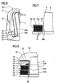
- FIG. 1 is an embodiment of an electric motor designed as an electric motor 1 with a base body 2 to be wound and a rotatably mounted about a rotation axis 3 rotor 4 shown.
- the main body 2 belongs to a stator of the electric machine 1 and is designed as a stator laminated core. He has axial end faces 5 and 6, on each of which an electrically insulating end plate 7 and 8 is arranged.
- the end plates 7 and 8 have axially projecting and uniformly distributed in the circumferential direction separating webs 9.
- the base body 2 has a stator inner bore, in which the in FIG. 2 unregistered runner 4 is placed. Adjacent to an inner wall of this stator inner bore axially extending and evenly distributed over the circumference grooves 10 are provided in the base body 2.
- the Nutverlauf deviating from the exact axial direction have a slight skew. Between the grooves 10 Nutstege 11 are arranged.
- the insulating end plates 7 and 8 are arranged on the end faces 5 and 6, that their partitions 9 are aligned with the Nutstegen 11.
- the number of dividers 9 and the Nutstege 11 is the same.
- electrical conductors 12 of an electrical winding system 13 to be introduced into the main body 2 are placed.
- the main body 2 is shown in a partially wound state. Only in some of the grooves 10 electrical conductors 12 are arranged.
- the grooves 10 Nutstirnö réelleen 14 from which the electrical conductors 12 emerge to the outside of the body 2 at the end faces 5 and 6 deflected and guided to another of the grooves 10 to become.
- This deflection and guidance of the electrical conductors 12 takes place in accordance with the exemplary embodiment 1 and 2 by means of the insulating end disks 7 and 8. In FIG. 2 is this deflection and conductor guidance indicated in a schematic.
- the end plates 7 and 8 are universally applicable. With them winding systems 13 can be realized for different numbers of poles. During the winding of the main body 2 and also of the end disks 7 and 8 with the electrical conductors 12, high tensile stresses and high friction between the separating webs 9 and the electrical conductors 12 can occur. This can lead to a bending and / or damaging of the separating webs on the one hand and to damage of the electrical conductors, for example their electrical insulation, on the other hand.
- the auxiliary winding body 16 is formed as a winding shoe and has the shape of a circular arc portion. Its outer wall 17 is smooth and has rounded outer edge edges 18. It has a rounded surface contour and is made in the embodiment of aluminum.
- a winding auxiliary body 16 at one of the two end faces 5 and 6 are arranged so that it covers within the circumferentially extending bridging region 15 during this part winding operation not to be wound groove end openings 14.
- the electrical conductor 12 is inserted into one of the grooves 10, the Nutstirnö réelle 14 is located on one of the circumferentially facing side of the bridging region 15, and by the associated uncovered Nutstirnö réelle 14 led out.
- auxiliary winding body 16 On an underside 19 of the auxiliary winding body 16 mounting recesses 20 are provided, which extend from the bottom 19, starting in the auxiliary winding body 16. Also at its two circumferentially facing side cheeks of the auxiliary winding body 16 each have a lateral recess 21, by means of each of the two arranged at the edge of the bridging region 15 dividers 9 is held and protected.
- the outer wall 17 has a projecting beyond the underside 19 projection 22 which does not extend in the circumferential direction over the entire circular arc portion, which covers the rest of the auxiliary winding body 16.
- the projection 22 serves as well as the smooth outer wall 17 for targeted guidance of the electrical conductor 12.
- the just introduced electrical conductor 12 is performed in connection with the deflection in the outer region of the base body 2 on the smooth outer wall 17 of the auxiliary winding body 16 and - FIG. 4 and 6 indicated by the directional arrows - pulled down.
- the projection 22 provided at the end in this direction of movement allows the electrical conductor 12 to be directed into a position between the auxiliary winding body 16 and the end plate 7 arranged guide element 23 with U-profile ( 3 and 4 ) or guide element 24 with L-profile ( FIG.
- the U-profiled guide member 23 has two U-legs 23a and 23b and a U-bottom 23c.
- the L-profiled guide member 24 has an L-leg 24a and an L-bottom 24b. Both guide elements 23 and 24 are also circular arc-shaped. Im in FIG. 4 and 6 shown state is in each case one turn of the electrical conductor 12 already in the respectively associated guide member 23 and 24, while the next turn is being made, wherein the electrical conductor 12 is guided on the smooth outer wall 17 of the auxiliary winding body 16 along.
- a contact surface 25 for the guide element 23 or 24 is provided adjacent to the projection 22.
- the guide element 23 and 24 is fixed in its position that there is no undesired positional shift during the winding process.
- the guide elements 23 and 24 have an electrically insulating function, which is ensured by the advantageous positional fixation after the winding process in full.
- it may come under the influence of tensile stresses during the winding process to a shift of the insulation and thus to a deterioration of the insulating properties. This disadvantage is circumvented by the positional fixing of the guide element 23 or 24.
- the auxiliary winding body 16 allows a largely uniform winding of the guide elements 23 and 24 with the individual turns of the electrical conductor 12.
- the dimensions of a thus produced and in FIG. 7 shown partial winding 26 can be pre-adjusted in advance via a corresponding dimensioning of the auxiliary winding body 16 and the guide member 23 and 24 respectively.
- a good utilization of space, especially in the radial direction is achieved.
- the resulting part windings extend more in the axial direction and less in the radial direction. This results in an axially longer overall structure.
- the electric machine 1 which is wound with the favorable winding method and using the favorable guide elements 23 and 24, characterized by a significantly better space utilization and thus by a shorter axial extent.
- the favorable Wicklungs vide and the favorable guide elements 23 and 24 can be used either in combination or as an individual measure, so either the Wickling process or the guide elements 23 and 24, are used.
- the resulting winding system 13 is also in the region of the end faces 5 and 6, in which winding heads not shown are formed, very close to the base body 2, so that a good thermal coupling is given. This has a favorable effect on the removal of the heat arising in the electrical conductors 12 in the region of the winding heads via the stator laminated core of the base body 2.
- FIG. 7 has the L-shaped guide member 24 in the outer region of the bending edge between the L-leg 24a and the L-bottom 24b has a recess 27 into which an L-bottom 28b of another L-profiled guide member 28 can engage.
- a stacked in the axial direction and fixed in position construction of a plurality of guide elements 24 and 28 can be realized.
- Exemplary is in FIG. 8 an embodiment with three adjacent stacked guide elements 24, 28 and 29 shown.
- the L-bottoms 28b and 29b of the guide elements 28 and 29 are fixed in the recess 27 of the underlying guide element 24 and 28 and the L-bottom 24b of the lowermost guide element 24 in an analogous designed recess 30 of the end plate 7.
- FIG. 8 shows a state in which the guide elements 24 and 28 are already completely wound with the partial winding 26 and with a partial winding 31.
- the third guide element 29 is being wound with the electrical conductors 12 of a further partial winding 32.
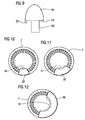
- FIG. 9 another embodiment of a winding auxiliary body 35 is shown.
- the winding auxiliary body 35 has at least one fastening extension 36 on its underside 19 instead of the fastening recesses 20, which extends axially downwards from the underside 19 and is intended to engage in one of the grooves 10 of the base body 2.
- the auxiliary winding body 35 is thus inserted directly on the base body 2.
- An end plate 7 or 8 as in the embodiments described above is not required.
- FIGS. 10 to 12 Further embodiments of winding auxiliary body 37, 38 and 39 are shown, which are used in conjunction with the end plate 7 or 8 during the winding process. They differ in the size of each covered circular arc section.
- the auxiliary winding bodies 37 to 39 are each intended for different embodiments of the electric machine 1. In particular, winding systems 13 with different numbers of poles can be realized in this way.
- the auxiliary winding bodies 37 to 39 each have a different covering area 40, 41 and 42, respectively. A different number of slot end openings 14 is covered in each case and bridged over for the guidance of the electrical conductor 12.
- the each used with - in FIGS. 10 to 12 not visible - guide elements cover the same arc section as the winding auxiliary body 37 to 39.
- winding heads with a comparatively large radial and short axial dimension can be realized in this way.
- the radial space is used almost completely up to the outer periphery of the main body 2. Due to this good space utilization in the radial direction, the shortening results in the axial direction, so that other components of the electric machine 1 such. B. the housing and / or the end shields can be performed axially shortened. This reduces the use of materials.
- the electrical operating data of the electric machine are improved. For example, the efficiency increases due to lower copper losses.
- winding auxiliary body 16, 33, 35, 37, 38 or 39 and in particular also the guide elements 23, 24, 28 or 29 allows a comparable embodiment of the various part windings 26, 31, and 32 of the winding system 13.
- these partial windings have 26th , 31, and 32 have a substantially same or at least very similar mean coil length and a substantially equal electrical resistance.
Landscapes
- Engineering & Computer Science (AREA)
- Manufacturing & Machinery (AREA)
- Power Engineering (AREA)
- Manufacture Of Motors, Generators (AREA)
Claims (9)
- Procédé pour effectuer un enroulement dans une machine ( 1 ) électrique qui comporte un axe ( 3 ) de rotation et un corps ( 2 ) de base ayant deux côtés ( 5, 6 ) frontaux axiaux ainsi que des encoches ( 10 ) de logement de conducteurs ( 12 ) électriques d'un système ( 13 ) d'enroulement, les encoches ( 10 ) ayant respectivement une ouverture ( 14 ) frontale d'encoche sur les côtés ( 5, 6 ) frontaux et, pour ménager un premier enroulement ( 26 ) partiel du système ( 13 ) d'enroulement,a) un corps ( 16 ; 33 ; 37 ; 38 ; 39 ) auxiliaire d'enroulement est disposé sur au moins l'un des côtés ( 5, 6 ) frontaux de manière à ce qu'il recouvre dans une zone ( 15 ; 40 ; 41 ; 42 ) de superposition s'étendant dans la direction périphérique au moins l'une des ouvertures ( 14 ) frontales d'encoche,b) les conducteurs ( 12 )b1) sont insérés dans au moins l'une des encoches ( 10 ), dont l'ouverture ( 14 ) frontale d'encoche se trouve sur un côté de la zone ( 15 ; 40 ; 41 ; 42 ) de superposition et sont sortis par l'ouverture ( 14 ) frontale d'encoche non recouverte,b2) sont déviés sur le côté ( 5, 6 ) frontal au moyen du corps ( 16 ; 33 ; 37 ; 38 ; 39 ) auxiliaire d'enroulement et sont guidés vers une autre non recouverte des ouvertures ( 14 ) frontales d'encoche, qui se trouve de l'autre côté de la zone ( 15 ; 40 ; 41 ; 42 ) de superposition,c) sur le côté ( 5, 6 ) frontal est disposé un flasque ( 7, 8 ) d'extrémité ayant des éléments ( 9 ) de séparation en saillie axialement et le corps ( 16 ; 33 ; 37 ; 38 ; 39 ) auxiliaire d'enroulement a des évidements ( 20 ) axiaux de fixation par lesquels il est, pour le montage, enfilé du côté ( 5, 6 ) frontal sur les éléments ( 9 ) de séparation, des nervures ( 11 ) étant disposées entre les encoches ( 10 ) et les flasques ( 7, 8 ) d'extrémité étant disposés sur les côtés ( 5, 6 ) frontaux de manière à ce que les éléments ( 9 ) de séparation soient alignés avec les nervures ( 11 ) et,d) le corps ( 16 ; 33 ; 37 ; 38 ; 39 ) auxiliaire d'enroulement est retiré après achèvement du premier enroulement ( 26 ) partiel.
- Procédé suivant la revendication 1, caractérisé en ce qu'entre les côtés ( 5, 6 ) frontaux et le corps ( 16 ; 33 ; 37 ; 38 ; 39 ) auxiliaire d'enroulement est placé, dans la zone ( 15 ; 40 ; 41 ; 42 ) de superposition, un premier élément ( 23 ; 24 ) de guidage, dans lequel les conducteurs ( 12 ) électriques viennent se mettre après le guidage au moyen du corps ( 16 ; 33 ; 37 ; 38 ; 39 ) auxiliaire d'enroulement.
- Procédé suivant la revendication 2, caractérisé en ce que le premier élément ( 23 ; 24 ) de guidage est immobilisé en sa position au moyen du corps ( 16 ; 33 ; 37 ; 38 ; 39 ) auxiliaire d'enroulement pendant la production du premier enroulement ( 26 ) partiel.
- Procédé suivant la revendication 2, caractérisé en ce qu'après l'achèvement du premier enroulement ( 26 ) partiel on place au voisinage du premier élément ( 24 ) de guidage un autre élément ( 28 ; 29 ) de guidage pour la réception des conducteurs ( 12 ) électriques d'un autre enroulement ( 31 ; 32 ) partiel.
- Procédé suivant la revendication 4, caractérisé en ce que sur l'autre élément ( 29 ) de guidage est monté un autre corps ( 33 ) auxiliaire d'enroulement, au moyen duquel les conducteurs ( 12 ) électriques sont guidés pendant la production de l'autre enroulement ( 32 ) partiel.
- Corps auxiliaire d'enroulement pour la mise en oeuvre du procédé suivant l'une des revendications précédentes, qui, pour le guidage dans une grande mesure glissant de conducteurs ( 12 ) électriques vers les autres ouvertures ( 14 ) frontales d'encoches non recouvertes de la machine ( 1 ) électrique, a une paroi ( 17 ) extérieure lisse ayant des bords ( 18 ) extérieurs de paroi arrondis et ayant un contour de surface notamment arrondie et qui est disposé, pour la production du premier enroulement ( 26 ) partiel du système ( 13 ) d'enroulement, sur au moins l'un des côtés ( 5 ; 6 ) frontaux de manière à ce qu'il recouvre au moins l'une des ouvertures ( 14 ) frontales d'encoche dans une zone ( 15 ; 40 ; 41 ; 42 ) de superposition s'étendant dans la direction périphérique et il est prévu des évidements ( 20 ) axiaux de fixation, qui s'étendent à partir du côté ( 19 ) inférieur s'étendant à peu près perpendiculairement à la paroi ( 17 ) extérieure dans le corps ( 16 ; 33 ; 37 ; 38 ; 39 ) auxiliaire d'enroulement, les évidements ( 20 ) axiaux de fixation pouvant être enfilés sur les éléments ( 9 ) de séparation d'un flasque ( 7 ; 8 ) d'extrémité disposé sur le côté ( 5 ; 6 ) frontal du corps ( 2 ) de base, les flasques ( 7 ; 8 ) d'extrémité étant disposés sur les côtés ( 5 ; 6 ) frontaux de manière à ce que les éléments ( 9 ) de séparation soient alignés avec les nervures ( 11 ) des encoches.
- Corps auxiliaire d'enroulement suivant la revendication 6, caractérisé en ce que le côté ( 19 ) inférieur est constitué au moins en partie sous la forme d'une surface ( 25 ) d'appui d'un élément ( 23 ; 24 ; 28 ; 29 ) de guidage des conducteurs ( 12 ) électriques.
- Corps auxiliaire d'enroulement suivant la revendication 7, caractérisé en ce que la surface ( 25 ) d'appui est constituée sous la forme d'une cavité ( 34 ) sur le côté ( 19 ) inférieur.
- Corps auxiliaire d'enroulement suivant la revendication 7, caractérisé en ce que la paroi ( 17 ) extérieure a une saillie ( 22 ) qui dépasse de la surface ( 25 ) d'appui du côté ( 19 ) inférieur.
Applications Claiming Priority (2)
| Application Number | Priority Date | Filing Date | Title |
|---|---|---|---|
| DE102005037375A DE102005037375B4 (de) | 2005-08-08 | 2005-08-08 | Verfahren zur Bewicklung einer elektrischen Maschine |
| PCT/EP2006/064667 WO2007017380A1 (fr) | 2005-08-08 | 2006-07-26 | Procede pour realiser un enroulement dans une machine electrique, et corps d'assistance a l'enroulement |
Publications (2)
| Publication Number | Publication Date |
|---|---|
| EP1913678A1 EP1913678A1 (fr) | 2008-04-23 |
| EP1913678B1 true EP1913678B1 (fr) | 2011-11-30 |
Family
ID=37434380
Family Applications (1)
| Application Number | Title | Priority Date | Filing Date |
|---|---|---|---|
| EP06777978A Active EP1913678B1 (fr) | 2005-08-08 | 2006-07-26 | Procede pour realiser un enroulement dans une machine electrique, et corps d'assistance a l'enroulement |
Country Status (7)
| Country | Link |
|---|---|
| US (1) | US7780108B2 (fr) |
| EP (1) | EP1913678B1 (fr) |
| CN (1) | CN101238630B (fr) |
| AT (1) | ATE535985T1 (fr) |
| BR (1) | BRPI0614553B1 (fr) |
| DE (1) | DE102005037375B4 (fr) |
| WO (1) | WO2007017380A1 (fr) |
Families Citing this family (11)
| Publication number | Priority date | Publication date | Assignee | Title |
|---|---|---|---|---|
| DE102011002933A1 (de) | 2011-01-20 | 2012-07-26 | Siemens Aktiengesellschaft | Stator einer elektrischen Maschine mit einem Kontaktierelement |
| CN102244441B (zh) * | 2011-06-16 | 2013-07-03 | 许晓华 | 线圈线包爬电距离的定型工装改进结构 |
| DE102011082353B4 (de) | 2011-09-08 | 2021-04-01 | Siemens Aktiengesellschaft | Stator für einen Elektromotor |
| DE102011083577A1 (de) | 2011-09-28 | 2013-03-28 | Siemens Aktiengesellschaft | Elektrische Maschine mit Stator mit variablem Nutabstand |
| CN102497068B (zh) * | 2011-11-30 | 2014-07-09 | 南车株洲电机有限公司 | 直驱风力发电机多匝成型绕组翻槽工艺及辅助装置 |
| DE102013003835A1 (de) * | 2013-03-07 | 2014-09-11 | Sew-Eurodrive Gmbh & Co Kg | Mehrphasig versorgter Elektromotor mit Stator |
| DE102013216210B4 (de) | 2013-08-15 | 2022-04-28 | Volkswagen Aktiengesellschaft | Wickelkörper für einen Stator eines Elektromotors |
| DE102014009799A1 (de) * | 2014-07-03 | 2016-01-07 | Audi Ag | Verfahren und Vorrichtung zur Herstellung einer Elektromaschine |
| EP3182559B1 (fr) | 2015-12-14 | 2018-01-31 | Siemens Aktiengesellschaft | Alignement de rotor destiné à réduire les vibrations et les bruits |
| DE102015016652B3 (de) * | 2015-12-19 | 2017-02-09 | Audi Ag | Verfahren zum Aufbringen einer Wicklung auf einem Stator |
| US11588363B2 (en) | 2020-07-25 | 2023-02-21 | Beta Air, Llc | Integrated electric propulsion assembly |
Family Cites Families (19)
| Publication number | Priority date | Publication date | Assignee | Title |
|---|---|---|---|---|
| DE1170526B (de) * | 1959-04-17 | 1964-05-21 | Fort Wayne Tool & Die Inc | Vorrichtung zur Bildung der Wickelkoepfe von mehrteiligen, konzentrischen Spulen bei Staenderwickelmaschinen |
| CH423960A (de) * | 1962-09-07 | 1966-11-15 | Asea Ab | Vorrichtung zum Einschieben und Herausziehen zweiteiliger Formstückpaare an einer Wickelmaschine für Ständer von elektrischen Maschinen |
| DE1257268B (de) * | 1962-11-08 | 1967-12-28 | Frieseke & Hoepfner Gmbh | Einwindeform fuer Vorrichtungen zum Einlegen von Draehten in die Statornuten elektrischer Maschinen |
| US3253792A (en) * | 1963-04-19 | 1966-05-31 | Fort Wayne Tool & Die Inc | Stator winding machine and tooling therefor |
| US3281084A (en) * | 1963-04-25 | 1966-10-25 | Fort Wayne Tool & Die Inc | Device for shaping and positioning dynamoelectric machine end turns |
| US3441226A (en) | 1965-07-19 | 1969-04-29 | Camillo Bargero | Cylindrical mill for grinding cement |
| GB1060738A (en) * | 1965-08-18 | 1967-03-08 | Fort Wayne Tool & Die Inc | Device and method for shaping and positioning dynamoelectric machine end turns |
| US3441228A (en) * | 1966-03-21 | 1969-04-29 | Fort Wayne Tool & Die Inc | End turn shaping and positioning apparatus for stator winding machine |
| GB1149264A (en) * | 1966-05-14 | 1969-04-23 | Elektromat Veb | A coil supporting assembly |
| CH493137A (de) * | 1969-07-16 | 1970-06-30 | Rotel Ag | Hilfskörper zum Wickeln von Statoren und Rotoren |
| US3648938A (en) * | 1970-08-05 | 1972-03-14 | Universal Electric Co | Winding of electric motors |
| US3861026A (en) * | 1971-09-15 | 1975-01-21 | Gen Electric | Method of making dynamoelectric machines |
| JPS60148360A (ja) * | 1984-01-11 | 1985-08-05 | Matsushita Electric Ind Co Ltd | ステ−タ巻線用ガイド治具 |
| FR2569503B1 (fr) | 1984-08-22 | 1988-07-22 | Etri Sa | Moteur electrique a element electromagnetique exterieur, procede pour le realiser, et habillage isolant et dispositif de guidage pour la mise en oeuvre du procede |
| CA2092264A1 (fr) * | 1992-04-15 | 1993-10-16 | Massimo Ponzio | Methodes et appareils d'enroulement de stator |
| US5491886A (en) * | 1993-08-12 | 1996-02-20 | Emerson Electric Co. | Gapless inner diameter stator winding blocking mechanism |
| US5845863A (en) * | 1995-11-06 | 1998-12-08 | Sony Corporation | Winding apparatus for simultaneous winding of two CRT yokes |
| EP1225679B1 (fr) * | 2001-01-19 | 2004-08-18 | ATS Wickel- und Montagetechnik AG | Procédé et dispositif pour enrouler des bobines magnétiques de stators à deux pôles |
| JP4725721B2 (ja) * | 2005-01-24 | 2011-07-13 | 株式会社富士通ゼネラル | アキシャルエアギャップ型電動機 |
-
2005
- 2005-08-08 DE DE102005037375A patent/DE102005037375B4/de not_active Expired - Fee Related
-
2006
- 2006-07-26 US US12/063,302 patent/US7780108B2/en active Active
- 2006-07-26 AT AT06777978T patent/ATE535985T1/de active
- 2006-07-26 CN CN200680029202.2A patent/CN101238630B/zh active Active
- 2006-07-26 WO PCT/EP2006/064667 patent/WO2007017380A1/fr active Application Filing
- 2006-07-26 BR BRPI0614553-1A patent/BRPI0614553B1/pt not_active IP Right Cessation
- 2006-07-26 EP EP06777978A patent/EP1913678B1/fr active Active
Also Published As
| Publication number | Publication date |
|---|---|
| ATE535985T1 (de) | 2011-12-15 |
| BRPI0614553A2 (pt) | 2011-03-29 |
| CN101238630A (zh) | 2008-08-06 |
| US7780108B2 (en) | 2010-08-24 |
| WO2007017380A1 (fr) | 2007-02-15 |
| DE102005037375A1 (de) | 2007-02-15 |
| CN101238630B (zh) | 2011-10-12 |
| EP1913678A1 (fr) | 2008-04-23 |
| DE102005037375B4 (de) | 2007-08-30 |
| US20080296427A1 (en) | 2008-12-04 |
| BRPI0614553B1 (pt) | 2018-06-05 |
Similar Documents
| Publication | Publication Date | Title |
|---|---|---|
| EP1913678B1 (fr) | Procede pour realiser un enroulement dans une machine electrique, et corps d'assistance a l'enroulement | |
| EP3391512B1 (fr) | Procédé d'insertion d'un film isolant et au moins un conducteur électrique | |
| DE102009032882B3 (de) | Herstellungsverfahren für Formspulen | |
| EP1913674B1 (fr) | Machine électrique comprenant une déviation côté frontal des conducteurs électriques | |
| DE10002485A1 (de) | Wickelkörper zur Aufnahme einer Wicklung für einen elektro-magneto-mechanischen Wandler sowie elektro-magneto-mechanischer Wandler | |
| DE102009008615A1 (de) | Verfahren zur Herstellung einer über den Umfang verteilten Statorwicklung und Motor mit einer solchen Statorwicklung | |
| DE112012003437T5 (de) | Statorherstellungsverfahren und Statorherstellungsvorrichtung | |
| EP2179490B1 (fr) | Support de bobine de contour special | |
| DE2630183B2 (de) | Verfahren und Vorrichtung zum Einziehen von Wicklungen in Nuten von Ankern und Statoren von Elektromotoren | |
| DE102015211836A1 (de) | Verfahren zum Bewickeln eines Stators, sowie ein Stator und eine elektrische Maschine beinhaltend einen solchen Stator | |
| DE2925062C2 (fr) | ||
| DE102019117966A1 (de) | Verfahren zur Herstellung einer Spulenwicklung zum Einlegen in radial offene Nuten von Statoren oder Rotoren von Elektromaschinen | |
| EP2994980B1 (fr) | Enroulement de stator traversant enroulé sur un support de bobine | |
| DE102018206003A1 (de) | Vorrichtung und Verfahren zur Ausrichtung einer Hairpinwicklung | |
| DE102011078025A1 (de) | Wickelkopfträger für einen Stator einer elektrischen Maschine | |
| DE102017216080A1 (de) | Stator für eine elektrische Maschine, eine elektrische Maschine und Verfahren zum Herstellen eines solchen Stators | |
| EP1633035A2 (fr) | Procédé d'enroulement d'un bobinage électrique pour une machine électrique | |
| EP2269285B1 (fr) | Procede et dispositif de fabrication d'un bobinage electrique | |
| EP3167540B1 (fr) | Procédé de fabrication d'une machine électrique comportant des bobines formées et machine électrique et outil de fabrication | |
| DE102019135138A1 (de) | Stator für eine elektrische Maschine, elektrische Maschine und Fahrzeug | |
| DE102007038429A1 (de) | Verfahren und Vorrichtung zur Herstellung einer elektrischen Wicklung | |
| DE1938244C2 (de) | Vorrichtung zum Einziehen von vorgefertigten Spulen aus Leiterdraht in vorbestimmte axiale Nuten von Statorkernen dynamoelektrischer Maschinen | |
| DE202017005871U1 (de) | Vorrichtung zur Anfertigung einer Wicklung | |
| EP4362287A1 (fr) | Moteur électrique pour pompe de fond de trou, procédé de fabrication et outil associés | |
| EP4362299A1 (fr) | Procédé et outil de fabrication d'un ensemble compact de bobines d'un moteur électrique pour une pompe de fond de trou |
Legal Events
| Date | Code | Title | Description |
|---|---|---|---|
| PUAI | Public reference made under article 153(3) epc to a published international application that has entered the european phase |
Free format text: ORIGINAL CODE: 0009012 |
|
| 17P | Request for examination filed |
Effective date: 20080109 |
|
| AK | Designated contracting states |
Kind code of ref document: A1 Designated state(s): AT BE BG CH CY CZ DE DK EE ES FI FR GB GR HU IE IS IT LI LT LU LV MC NL PL PT RO SE SI SK TR |
|
| 17Q | First examination report despatched |
Effective date: 20090414 |
|
| GRAP | Despatch of communication of intention to grant a patent |
Free format text: ORIGINAL CODE: EPIDOSNIGR1 |
|
| GRAS | Grant fee paid |
Free format text: ORIGINAL CODE: EPIDOSNIGR3 |
|
| GRAA | (expected) grant |
Free format text: ORIGINAL CODE: 0009210 |
|
| AK | Designated contracting states |
Kind code of ref document: B1 Designated state(s): AT BE BG CH CY CZ DE DK EE ES FI FR GB GR HU IE IS IT LI LT LU LV MC NL PL PT RO SE SI SK TR |
|
| DAX | Request for extension of the european patent (deleted) | ||
| REG | Reference to a national code |
Ref country code: CH Ref legal event code: EP Ref country code: GB Ref legal event code: FG4D Free format text: NOT ENGLISH |
|
| REG | Reference to a national code |
Ref country code: IE Ref legal event code: FG4D Free format text: LANGUAGE OF EP DOCUMENT: GERMAN |
|
| REG | Reference to a national code |
Ref country code: DE Ref legal event code: R096 Ref document number: 502006010665 Country of ref document: DE Effective date: 20120308 |
|
| REG | Reference to a national code |
Ref country code: NL Ref legal event code: VDEP Effective date: 20111130 |
|
| LTIE | Lt: invalidation of european patent or patent extension |
Effective date: 20111130 |
|
| PG25 | Lapsed in a contracting state [announced via postgrant information from national office to epo] |
Ref country code: IS Free format text: LAPSE BECAUSE OF FAILURE TO SUBMIT A TRANSLATION OF THE DESCRIPTION OR TO PAY THE FEE WITHIN THE PRESCRIBED TIME-LIMIT Effective date: 20120330 Ref country code: LT Free format text: LAPSE BECAUSE OF FAILURE TO SUBMIT A TRANSLATION OF THE DESCRIPTION OR TO PAY THE FEE WITHIN THE PRESCRIBED TIME-LIMIT Effective date: 20111130 |
|
| PG25 | Lapsed in a contracting state [announced via postgrant information from national office to epo] |
Ref country code: SI Free format text: LAPSE BECAUSE OF FAILURE TO SUBMIT A TRANSLATION OF THE DESCRIPTION OR TO PAY THE FEE WITHIN THE PRESCRIBED TIME-LIMIT Effective date: 20111130 Ref country code: NL Free format text: LAPSE BECAUSE OF FAILURE TO SUBMIT A TRANSLATION OF THE DESCRIPTION OR TO PAY THE FEE WITHIN THE PRESCRIBED TIME-LIMIT Effective date: 20111130 Ref country code: LV Free format text: LAPSE BECAUSE OF FAILURE TO SUBMIT A TRANSLATION OF THE DESCRIPTION OR TO PAY THE FEE WITHIN THE PRESCRIBED TIME-LIMIT Effective date: 20111130 Ref country code: SE Free format text: LAPSE BECAUSE OF FAILURE TO SUBMIT A TRANSLATION OF THE DESCRIPTION OR TO PAY THE FEE WITHIN THE PRESCRIBED TIME-LIMIT Effective date: 20111130 Ref country code: GR Free format text: LAPSE BECAUSE OF FAILURE TO SUBMIT A TRANSLATION OF THE DESCRIPTION OR TO PAY THE FEE WITHIN THE PRESCRIBED TIME-LIMIT Effective date: 20120301 Ref country code: PT Free format text: LAPSE BECAUSE OF FAILURE TO SUBMIT A TRANSLATION OF THE DESCRIPTION OR TO PAY THE FEE WITHIN THE PRESCRIBED TIME-LIMIT Effective date: 20120330 |
|
| REG | Reference to a national code |
Ref country code: IE Ref legal event code: FD4D |
|
| PG25 | Lapsed in a contracting state [announced via postgrant information from national office to epo] |
Ref country code: CY Free format text: LAPSE BECAUSE OF FAILURE TO SUBMIT A TRANSLATION OF THE DESCRIPTION OR TO PAY THE FEE WITHIN THE PRESCRIBED TIME-LIMIT Effective date: 20111130 |
|
| PG25 | Lapsed in a contracting state [announced via postgrant information from national office to epo] |
Ref country code: DK Free format text: LAPSE BECAUSE OF FAILURE TO SUBMIT A TRANSLATION OF THE DESCRIPTION OR TO PAY THE FEE WITHIN THE PRESCRIBED TIME-LIMIT Effective date: 20111130 Ref country code: SK Free format text: LAPSE BECAUSE OF FAILURE TO SUBMIT A TRANSLATION OF THE DESCRIPTION OR TO PAY THE FEE WITHIN THE PRESCRIBED TIME-LIMIT Effective date: 20111130 Ref country code: BG Free format text: LAPSE BECAUSE OF FAILURE TO SUBMIT A TRANSLATION OF THE DESCRIPTION OR TO PAY THE FEE WITHIN THE PRESCRIBED TIME-LIMIT Effective date: 20120229 Ref country code: EE Free format text: LAPSE BECAUSE OF FAILURE TO SUBMIT A TRANSLATION OF THE DESCRIPTION OR TO PAY THE FEE WITHIN THE PRESCRIBED TIME-LIMIT Effective date: 20111130 Ref country code: IE Free format text: LAPSE BECAUSE OF FAILURE TO SUBMIT A TRANSLATION OF THE DESCRIPTION OR TO PAY THE FEE WITHIN THE PRESCRIBED TIME-LIMIT Effective date: 20111130 Ref country code: CZ Free format text: LAPSE BECAUSE OF FAILURE TO SUBMIT A TRANSLATION OF THE DESCRIPTION OR TO PAY THE FEE WITHIN THE PRESCRIBED TIME-LIMIT Effective date: 20111130 |
|
| PG25 | Lapsed in a contracting state [announced via postgrant information from national office to epo] |
Ref country code: IT Free format text: LAPSE BECAUSE OF FAILURE TO SUBMIT A TRANSLATION OF THE DESCRIPTION OR TO PAY THE FEE WITHIN THE PRESCRIBED TIME-LIMIT Effective date: 20111130 Ref country code: RO Free format text: LAPSE BECAUSE OF FAILURE TO SUBMIT A TRANSLATION OF THE DESCRIPTION OR TO PAY THE FEE WITHIN THE PRESCRIBED TIME-LIMIT Effective date: 20111130 Ref country code: PL Free format text: LAPSE BECAUSE OF FAILURE TO SUBMIT A TRANSLATION OF THE DESCRIPTION OR TO PAY THE FEE WITHIN THE PRESCRIBED TIME-LIMIT Effective date: 20111130 |
|
| PLBE | No opposition filed within time limit |
Free format text: ORIGINAL CODE: 0009261 |
|
| STAA | Information on the status of an ep patent application or granted ep patent |
Free format text: STATUS: NO OPPOSITION FILED WITHIN TIME LIMIT |
|
| 26N | No opposition filed |
Effective date: 20120831 |
|
| REG | Reference to a national code |
Ref country code: DE Ref legal event code: R097 Ref document number: 502006010665 Country of ref document: DE Effective date: 20120831 |
|
| BERE | Be: lapsed |
Owner name: SIEMENS A.G. Effective date: 20120731 |
|
| PG25 | Lapsed in a contracting state [announced via postgrant information from national office to epo] |
Ref country code: MC Free format text: LAPSE BECAUSE OF NON-PAYMENT OF DUE FEES Effective date: 20120731 |
|
| REG | Reference to a national code |
Ref country code: CH Ref legal event code: PL |
|
| PG25 | Lapsed in a contracting state [announced via postgrant information from national office to epo] |
Ref country code: ES Free format text: LAPSE BECAUSE OF FAILURE TO SUBMIT A TRANSLATION OF THE DESCRIPTION OR TO PAY THE FEE WITHIN THE PRESCRIBED TIME-LIMIT Effective date: 20120311 Ref country code: CH Free format text: LAPSE BECAUSE OF NON-PAYMENT OF DUE FEES Effective date: 20120731 Ref country code: LI Free format text: LAPSE BECAUSE OF NON-PAYMENT OF DUE FEES Effective date: 20120731 |
|
| PG25 | Lapsed in a contracting state [announced via postgrant information from national office to epo] |
Ref country code: BE Free format text: LAPSE BECAUSE OF NON-PAYMENT OF DUE FEES Effective date: 20120731 |
|
| PG25 | Lapsed in a contracting state [announced via postgrant information from national office to epo] |
Ref country code: FI Free format text: LAPSE BECAUSE OF FAILURE TO SUBMIT A TRANSLATION OF THE DESCRIPTION OR TO PAY THE FEE WITHIN THE PRESCRIBED TIME-LIMIT Effective date: 20111130 |
|
| REG | Reference to a national code |
Ref country code: AT Ref legal event code: MM01 Ref document number: 535985 Country of ref document: AT Kind code of ref document: T Effective date: 20120731 |
|
| PG25 | Lapsed in a contracting state [announced via postgrant information from national office to epo] |
Ref country code: AT Free format text: LAPSE BECAUSE OF NON-PAYMENT OF DUE FEES Effective date: 20120731 |
|
| PGFP | Annual fee paid to national office [announced via postgrant information from national office to epo] |
Ref country code: FR Payment date: 20130724 Year of fee payment: 8 Ref country code: GB Payment date: 20130710 Year of fee payment: 8 |
|
| PG25 | Lapsed in a contracting state [announced via postgrant information from national office to epo] |
Ref country code: TR Free format text: LAPSE BECAUSE OF FAILURE TO SUBMIT A TRANSLATION OF THE DESCRIPTION OR TO PAY THE FEE WITHIN THE PRESCRIBED TIME-LIMIT Effective date: 20111130 |
|
| PG25 | Lapsed in a contracting state [announced via postgrant information from national office to epo] |
Ref country code: LU Free format text: LAPSE BECAUSE OF NON-PAYMENT OF DUE FEES Effective date: 20120726 |
|
| PG25 | Lapsed in a contracting state [announced via postgrant information from national office to epo] |
Ref country code: HU Free format text: LAPSE BECAUSE OF FAILURE TO SUBMIT A TRANSLATION OF THE DESCRIPTION OR TO PAY THE FEE WITHIN THE PRESCRIBED TIME-LIMIT Effective date: 20060726 |
|
| GBPC | Gb: european patent ceased through non-payment of renewal fee |
Effective date: 20140726 |
|
| REG | Reference to a national code |
Ref country code: FR Ref legal event code: ST Effective date: 20150331 |
|
| PG25 | Lapsed in a contracting state [announced via postgrant information from national office to epo] |
Ref country code: GB Free format text: LAPSE BECAUSE OF NON-PAYMENT OF DUE FEES Effective date: 20140726 Ref country code: FR Free format text: LAPSE BECAUSE OF NON-PAYMENT OF DUE FEES Effective date: 20140731 |
|
| PGFP | Annual fee paid to national office [announced via postgrant information from national office to epo] |
Ref country code: DE Payment date: 20230918 Year of fee payment: 18 |