EP1912064B1 - Gassensorelement - Google Patents
Gassensorelement Download PDFInfo
- Publication number
- EP1912064B1 EP1912064B1 EP06781189.3A EP06781189A EP1912064B1 EP 1912064 B1 EP1912064 B1 EP 1912064B1 EP 06781189 A EP06781189 A EP 06781189A EP 1912064 B1 EP1912064 B1 EP 1912064B1
- Authority
- EP
- European Patent Office
- Prior art keywords
- space
- oxygen
- gas
- pumping
- electrode
- Prior art date
- Legal status (The legal status is an assumption and is not a legal conclusion. Google has not performed a legal analysis and makes no representation as to the accuracy of the status listed.)
- Active
Links
- MWUXSHHQAYIFBG-UHFFFAOYSA-N Nitric oxide Chemical compound O=[N] MWUXSHHQAYIFBG-UHFFFAOYSA-N 0.000 claims description 243
- 238000005086 pumping Methods 0.000 claims description 120
- 239000007789 gas Substances 0.000 claims description 109
- 239000007784 solid electrolyte Substances 0.000 claims description 76
- 239000001301 oxygen Substances 0.000 claims description 68
- 229910052760 oxygen Inorganic materials 0.000 claims description 68
- QVGXLLKOCUKJST-UHFFFAOYSA-N atomic oxygen Chemical compound [O] QVGXLLKOCUKJST-UHFFFAOYSA-N 0.000 claims description 67
- 238000005259 measurement Methods 0.000 claims description 50
- 238000009792 diffusion process Methods 0.000 claims description 34
- PNEYBMLMFCGWSK-UHFFFAOYSA-N aluminium oxide Inorganic materials [O-2].[O-2].[O-2].[Al+3].[Al+3] PNEYBMLMFCGWSK-UHFFFAOYSA-N 0.000 claims description 14
- 230000009471 action Effects 0.000 claims description 11
- 229910000272 alkali metal oxide Inorganic materials 0.000 claims description 11
- 230000009467 reduction Effects 0.000 claims description 11
- VYPSYNLAJGMNEJ-UHFFFAOYSA-N Silicium dioxide Chemical compound O=[Si]=O VYPSYNLAJGMNEJ-UHFFFAOYSA-N 0.000 claims description 10
- 238000000354 decomposition reaction Methods 0.000 claims description 10
- 239000000377 silicon dioxide Substances 0.000 claims description 5
- 229910052744 lithium Inorganic materials 0.000 claims description 3
- 229910052708 sodium Inorganic materials 0.000 claims description 3
- 239000010410 layer Substances 0.000 description 156
- 238000005192 partition Methods 0.000 description 21
- 230000036961 partial effect Effects 0.000 description 17
- 239000000463 material Substances 0.000 description 14
- 229910044991 metal oxide Inorganic materials 0.000 description 12
- 150000004706 metal oxides Chemical class 0.000 description 12
- BASFCYQUMIYNBI-UHFFFAOYSA-N platinum Substances [Pt] BASFCYQUMIYNBI-UHFFFAOYSA-N 0.000 description 10
- MCMNRKCIXSYSNV-UHFFFAOYSA-N Zirconium dioxide Chemical compound O=[Zr]=O MCMNRKCIXSYSNV-UHFFFAOYSA-N 0.000 description 9
- 229910010293 ceramic material Inorganic materials 0.000 description 9
- 239000011195 cermet Substances 0.000 description 9
- 230000000694 effects Effects 0.000 description 6
- 239000010948 rhodium Substances 0.000 description 6
- 238000010304 firing Methods 0.000 description 5
- 229910052751 metal Inorganic materials 0.000 description 5
- 239000002184 metal Substances 0.000 description 5
- 239000011241 protective layer Substances 0.000 description 5
- 230000000452 restraining effect Effects 0.000 description 5
- 239000000919 ceramic Substances 0.000 description 4
- 150000001875 compounds Chemical class 0.000 description 4
- 229910000510 noble metal Inorganic materials 0.000 description 4
- 229910052697 platinum Inorganic materials 0.000 description 4
- 230000003197 catalytic effect Effects 0.000 description 3
- 239000007769 metal material Substances 0.000 description 3
- 238000000034 method Methods 0.000 description 3
- 230000010349 pulsation Effects 0.000 description 3
- 230000002829 reductive effect Effects 0.000 description 3
- 229910052703 rhodium Inorganic materials 0.000 description 3
- 239000007787 solid Substances 0.000 description 3
- 230000004913 activation Effects 0.000 description 2
- 229910045601 alloy Inorganic materials 0.000 description 2
- 239000000956 alloy Substances 0.000 description 2
- 230000008859 change Effects 0.000 description 2
- 239000000446 fuel Substances 0.000 description 2
- 230000001965 increasing effect Effects 0.000 description 2
- 239000000203 mixture Substances 0.000 description 2
- 125000006850 spacer group Chemical group 0.000 description 2
- YAPQBXQYLJRXSA-UHFFFAOYSA-N theobromine Chemical compound CN1C(=O)NC(=O)C2=C1N=CN2C YAPQBXQYLJRXSA-UHFFFAOYSA-N 0.000 description 2
- MYMOFIZGZYHOMD-UHFFFAOYSA-N Dioxygen Chemical compound O=O MYMOFIZGZYHOMD-UHFFFAOYSA-N 0.000 description 1
- FUJCRWPEOMXPAD-UHFFFAOYSA-N Li2O Inorganic materials [Li+].[Li+].[O-2] FUJCRWPEOMXPAD-UHFFFAOYSA-N 0.000 description 1
- KKCBUQHMOMHUOY-UHFFFAOYSA-N Na2O Inorganic materials [O-2].[Na+].[Na+] KKCBUQHMOMHUOY-UHFFFAOYSA-N 0.000 description 1
- 229910001260 Pt alloy Inorganic materials 0.000 description 1
- 229910018967 Pt—Rh Inorganic materials 0.000 description 1
- 230000002411 adverse Effects 0.000 description 1
- 229910052783 alkali metal Inorganic materials 0.000 description 1
- 150000001340 alkali metals Chemical class 0.000 description 1
- 229910000287 alkaline earth metal oxide Inorganic materials 0.000 description 1
- 238000002485 combustion reaction Methods 0.000 description 1
- 238000004891 communication Methods 0.000 description 1
- 239000000306 component Substances 0.000 description 1
- 239000004020 conductor Substances 0.000 description 1
- 239000000470 constituent Substances 0.000 description 1
- 238000010276 construction Methods 0.000 description 1
- 229910052593 corundum Inorganic materials 0.000 description 1
- XUCJHNOBJLKZNU-UHFFFAOYSA-M dilithium;hydroxide Chemical compound [Li+].[Li+].[OH-] XUCJHNOBJLKZNU-UHFFFAOYSA-M 0.000 description 1
- 229910001882 dioxygen Inorganic materials 0.000 description 1
- 238000010292 electrical insulation Methods 0.000 description 1
- 239000003792 electrolyte Substances 0.000 description 1
- 230000002708 enhancing effect Effects 0.000 description 1
- 230000020169 heat generation Effects 0.000 description 1
- 238000010438 heat treatment Methods 0.000 description 1
- 230000006872 improvement Effects 0.000 description 1
- 238000010030 laminating Methods 0.000 description 1
- -1 oxygen ion Chemical class 0.000 description 1
- 229910052700 potassium Inorganic materials 0.000 description 1
- 230000008569 process Effects 0.000 description 1
- 238000004080 punching Methods 0.000 description 1
- MHOVAHRLVXNVSD-UHFFFAOYSA-N rhodium atom Chemical compound [Rh] MHOVAHRLVXNVSD-UHFFFAOYSA-N 0.000 description 1
- 239000004071 soot Substances 0.000 description 1
- 229910052596 spinel Inorganic materials 0.000 description 1
- 239000011029 spinel Substances 0.000 description 1
- 229960004559 theobromine Drugs 0.000 description 1
- 230000003685 thermal hair damage Effects 0.000 description 1
- 238000009423 ventilation Methods 0.000 description 1
- 229910001845 yogo sapphire Inorganic materials 0.000 description 1
Images


Classifications
-
- G—PHYSICS
- G01—MEASURING; TESTING
- G01N—INVESTIGATING OR ANALYSING MATERIALS BY DETERMINING THEIR CHEMICAL OR PHYSICAL PROPERTIES
- G01N27/00—Investigating or analysing materials by the use of electric, electrochemical, or magnetic means
- G01N27/26—Investigating or analysing materials by the use of electric, electrochemical, or magnetic means by investigating electrochemical variables; by using electrolysis or electrophoresis
- G01N27/416—Systems
- G01N27/417—Systems using cells, i.e. more than one cell and probes with solid electrolytes
- G01N27/419—Measuring voltages or currents with a combination of oxygen pumping cells and oxygen concentration cells
Definitions
- the present invention relates to a nitrogen oxide (NOx) sensor containing a gas sensor element, suitably used to measure NO and, NO 2 , contained in automobile exhaust emissions and the atmosphere.
- NOx nitrogen oxide
- JP-A-8-271476 Patent Document 1
- JP-A-11-237362 Patent Document 2
- JP-A-2000-28576 Patent Document 3
- the disclosed measuring device uses a gas sensor element to detect the concentration of the desired gas component contained in the measurement gas.
- the gas sensor element has a laminar structure formed by laminating a plurality of solid electrolyte layers each having a suitable thickness integrally on each other.
- first internal space into which the measurement gas is introduced through a first diffusion controlling passage
- second internal space into which an atmosphere in the first internal space is introduced through a second diffusion controlling passage and in which the measurement gas component existing in the atmosphere is reduced or decomposed
- first oxygen pumping means to control an oxygen partial pressure in the first internal space
- second oxygen pumping means to pump the oxygen out of the second internal space
- current detecting means to detect a pumping current flowing upon a pumping action of the second oxygen pumping means.
- the gas sensor element detects the amount of the desired measurement gas component on the basis of the pumping current detected by the current detecting means.
- the gas sensor element disclosed in the above-indicated Patent Publications includes at least one pair of electrodes arranged to measure an electromotive force based on a difference in an oxygen concentration between atmospheres, for the purpose of detecting the oxygen concentration in the atmosphere, controlling the pumping action performed by the oxygen pumping means disposed in the element.
- the at least one pair of electrodes are provided in the solid electrolyte layers which are laminated integrally on each other, and cooperate with the above-indicated internal spaces, diffusion controlling passages, oxygen pumping means, etc., to constitute a sensor layer.
- a suitable heater layer is laminated integrally on the sensor layer to provide an integral element structure.
- the heater layer is constituted by including: a heater element having a heat generating portion; and an electrically insulating layer disposed so as to enclose the heater element.
- the above-described laminar-structured gas sensor element which has been conventionally proposed suffers from the following problem when used for measuring the measurement gas such as exhaust emissions. That is, when an electric current is supplied to the heater element of the heater layer of the gas sensor element and a prescribed pulse voltage is applied thereto, noise signal is generated, so that an output value of the electromotive force detected by the pair of electrodes provided in the sensor layer is influenced by the noise signal and undesirably suffers from fluctuations.
- a frequency of the voltage applied to the heater element in accordance with recent digitalization of a control circuit for the gas sensor element, such reduction in the frequency of the voltage to be applied to the heater element causes the fluctuations in the output value described above to become large.
- the gas sensor element does not ensure a sufficiently high degree of accuracy of detecting the measurement gas component.
- EP 0 845 669 describes an air/fuel ratio sensor formed of a detecting portion and a heater portion laminated via a porous body.
- a reference electrode is provided for controlling an oxygen gas diffusion rate
- a measurement electrode is provided on an outer face of the solid electrolytic body.
- a surface of the measurement electrode, on which the diffusion rate is not controlled, is covered with a protective layer having an ventilation property to a degree to which the diffusion rate is not substantially controlled.
- a lead portion of the reference electrode is a porous layer which substantially controls the diffusion rate. The lead portion is exposed to an exhaust gas via a connecting hole which connects the lead potion and the protective layer.
- US 2003/019486 describes a heater power supply control system for controlling the temperature of a heater used to heat a solid electrolyte-made sensor element of a gas concentration sensor to a desired activation temperature. It measures a resistance value of the sensor element and controls an electric power supply to the heater using a PI control function.
- the heater power supply control system works to limit the value of an integral term of the PI control function in the course of activation of the sensor element, thereby avoiding overshoot of the resistance value of the sensor element, which avoids thermal damage of the sensor element.
- EP 0 125 069 describes an electrochemical element to be used for, for example, an oxygen detector or controller, comprising an electrochemical cell having a solid electrolyte and at least a pair of porous electrodes in contact therewith and a heater contacting the electrolyte directly or via a high resistance layer and being insulated from said electrodes.
- an electron conductor embedded in a solid electrolyte is provided between the electrochemical cell and the heater.
- the present invention was made in view of the situations described above. It is therefore an object of the invention to provide a nitrogen oxide (NOx) sensor having a gas sensor element having a laminar structure in which a sensor layer and a heater layer are laminated integrally on each other, which gas sensor element is capable of restraining or preventing an influence of signal noise generated by application of a voltage to the heater element of the heater layer and thereby permitting output values to be obtained with high accuracy and high stability.
- NOx nitrogen oxide
- the present invention provides a nitrogen oxide sensor as set out in claim 1.
- a total content of the at least one metal oxide in the electrically insulating layer is in a range of 2.5-5 wt%.
- the electrically insulating layer is advantageously formed of alumina, or alumina and silica.
- the alkali metal oxide includes an oxide of Li, Na, or K.
- the electrically insulating layer of the heater layer is enclosed by the solid electrolyte.
- the at least one pair of electrodes include a first measuring electrode exposed to an external measurement gas and a reference electrode exposed to a reference gas having a reference oxygen concentration.
- the nitrogen oxide sensor further comprises first oxygen-partial-pressure detecting means which includes, as the at least one pair of electrodes, a first measuring electrode disposed so as to be in contact with the external measurement gas and a reference electrode disposed so as to be in contact with the reference gas in the reference-gas space, the first oxygen-partial-pressure detecting means being configured to detect an electromotive force corresponding to a difference in an oxygen concentration between the measurement gas and the reference gas.
- the nitrogen oxide sensor further comprises main pumping means which includes a first inner pumping electrode and a first outer pumping electrode respectively formed inside and outside of the first space, the main pumping means performing a pumping action with respect to oxygen contained in the measurement gas which has been introduced into the first space from the gas inlet, based on a control voltage applied between the first inner and outer pumping electrodes.
- the nitrogen oxide sensor further comprises measuring pumping means which includes: a second inner pumping electrode which is formed inside of the second space and which reduces or decomposes the nitrogen oxide component contained in the atmosphere that has been introduced from the first space, as a result of contact with the atmosphere; and a second outer pumping electrode formed outside of the second space, the measuring pumping means performing a pumping action with respect to oxygen generated by reduction or decomposition of the nitrogen oxide component contained in the atmosphere which has been introduced from the first space, based on a voltage applied between the second inner and outer pumping electrodes.
- the nitrogen oxide sensor further comprises auxiliary pumping means which includes a pair of auxiliary pumping electrodes respectively formed inside and outside of the second space, the auxiliary pumping means performing a pumping action with respect to oxygen contained in the atmosphere which has been introduced from the first space, based on an auxiliary pumping voltage applied between the pair of auxiliary pumping electrodes.
- the nitrogen oxide sensor further comprises second oxygen-partial-pressure detecting means which includes: a second measuring electrode disposed so as to be in contact with the atmosphere in the first space; and a reference electrode disposed so as to be in contact with the reference gas in the reference-gas space, the second oxygen-partial-pressure detecting means being configured to detect an electromotive force corresponding to a difference in an oxygen concentration between the atmosphere in the first space and the reference gas.
- second oxygen-partial-pressure detecting means which includes: a second measuring electrode disposed so as to be in contact with the atmosphere in the first space; and a reference electrode disposed so as to be in contact with the reference gas in the reference-gas space, the second oxygen-partial-pressure detecting means being configured to detect an electromotive force corresponding to a difference in an oxygen concentration between the atmosphere in the first space and the reference gas.
- the nitrogen oxide sensor further comprises third oxygen-partial-pressure detecting means which includes: a third measuring electrode disposed so as to be in contact with an atmosphere in the second space and a reference electrode disposed so as to be in contact with the reference gas in the reference-gas space, the third oxygen-partial-pressure detecting means being configured to detect an electromotive force corresponding to a difference in an oxygen concentration between the atmosphere in the second space and the reference gas.
- the nitrogen oxide sensor further comprises fourth oxygen-partial-pressure detecting means which includes: a fourth measuring electrode which is disposed in the second space and which reduces or decomposes the nitrogen oxide component contained in the atmosphere which has been introduced from the first space; and a reference electrode which is disposed so as to be in contact with the reference gas in the reference-gas space, the fourth oxygen-partial-pressure detecting means being configured to detect an electromotive force corresponding to a difference between an amount of oxygen generated by reduction or decomposition of the nitrogen oxide component contained in the atmosphere which has been introduced from the first space and an amount of oxygen contained in the reference gas.
- At least one alkali metal oxide is contained in the electrically insulating layer disposed so as to enclose the heater element of the heater layer which is laminated integrally on the sensor layer.
- the arrangement effectively increases resistance between the heater element and the sensor layer, accordingly the at least one pair of electrodes. Accordingly, even when a voltage is applied to the heater element of the heater layer for heat generation, the influence of the generated signal noise can be effectively restrained or prevented, thereby permitting accurate output values to be obtained from the sensor layer.
- the measurement gas component can be detected by the gas sensor element with high accuracy and high stability.
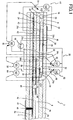
- Figs. 1-3 schematically show a construction of a representative example of a NOx (nitrogen oxide) sensor element as one example of a gas sensor element of a sensor according to the present invention.
- Fig. 1 is a view showing a laminar structure of the element in longitudinal cross section.
- Fig. 2 is a cross-sectional view of the element taken along line II-II in Fig. 1 .
- Fig. 3 is a perspective view showing a heater element and an electrically insulating layer which constitute a heater layer in the NOx sensor element shown in Fig. 1 .
- the sensor element indicated at 2 in these figures has a generally elongate plate-like shape with a relatively small width and a relatively large length.
- the sensor element 2 has a laminar structure which includes dense and air-tight oxygen-ion conductive solid electrolyte layers 4a, 4b, 4c, 4d, 4e, and 4f which are laminated on each other so as to provide an integral structure.
- the solid electrolyte layers 4a-4f are formed of a known oxygen-ion conductive solid electrolyte material such as zirconia ceramics.
- the integral sensor element 2 is easily produced by firing a laminar structure of unfired solid electrolyte layers, as know in the art.
- an uppermost solid electrolyte layer 4a and a third solid electrolyte layer 4c from the top in Fig. 1 are laminated on each other with a spacer layer in the form of the solid electrolyte layer 4b being interposed therebetween, thereby defining internal spaces which are located between the solid electrolyte layers 4a, 4c and which have a height corresponding to the thickness of the solid electrolyte layer 4b.
- the internal spaces in which the solid electrolyte layer 4b does not exist are formed so as to extend in a longitudinal direction of the sensor element 2.
- the sensor element 2 further has a reference-air introducing passage 6 as a reference-gas space which is formed between the solid electrolyte layers 4b, 4d independently of the internal spaces described above.
- the reference-air introducing passage 6 in which the solid electrolyte layer 4c does not exist is formed so as to extend in the longitudinal direction of the sensor element 2.
- the reference-air introducing passage 6 is open to the atmosphere at a proximal end of the sensor element 2 (i.e., a right-side in Fig. 1 )
- the internal spaces formed between the two solid electrolyte layers 4a, 4c in the sensor element 2 include a buffer space 8, a first space 10, and a second space 12 which are formed independently of each other and arranged in the order of description in the longitudinal direction of the sensor element 2.
- the buffer space 8 and the first and second spaces 10, 12 have rectangular shapes and predetermined width dimensions in plan view.
- a clogging-preventive space 14 is formed at a distal end of the sensor element 2 so as to be located between the two solid electrolyte layers 4a, 4c with a height corresponding to the thickness of the solid electrolyte layer 4b, like the buffer space 8 and the first and second spaces 10, 12.
- the clogging-preventive space 14 in which the solid electrolyte layer 4b as the spacer layer does not exist is open outward, and the open end of the clogging-preventive space 14 is made as a gas inlet 16 through which a measurement gas existing in an external space outside the sensor element 2 is introduced.
- the clogging-preventive space 14 and the buffer space 8 are separated from each other by a first partition wall 18 provided by a portion of the solid electrolyte layer 4b.
- the first partition wall 18 cooperates with the solid electrolyte layers 4a, 4c which are respectively located on upper and lower sides of the first partition wall 18, to define slits at upper and lower portions of the partition wall 18, respectively.
- the slits have a width substantially equal to that of the buffer space 8 and extend in a width direction of the element.
- the slits function as first diffusion controlling passages 20 each as first diffusion controlling means.
- the measurement gas existing in the external space outside the sensor element 2 which has been introduced into the clogging-preventive space 14 through the gas inlet 16 is introduced into the buffer space 8, under a prescribed diffusion resistance, through the first diffusion controlling passages 20 formed on the upper and lower sides of the first partition wall 18.
- the buffer space 8 and the first space 10 are separated from each other by a second partition wall 22 provided by a portion of the solid electrolyte layer 4b.
- the second partition wall 22 cooperates with the solid electrolyte layers 4a, 4c which are respectively located near to and remote from the external space, to define slits at upper and lower portions of the second partition wall 22, respectively.
- the slits that extend in the width direction of the element function as second diffusion controlling passages 24 each as second diffusion controlling means.
- An atmosphere (measurement gas) existing in the buffer space 8 is introduced into the first space 10, under a prescribed diffusion resistance, through the second diffusion controlling passages 24.
- the sensor element 2 has main pumping means which is an electrochemical pumping cell constituted by the solid electrolyte layer 4a, an inner pumping electrode 26 and an outer pumping electrode 28 formed on respective inner and outer surfaces of the solid electrolyte layer 4a.
- main pumping means which is an electrochemical pumping cell constituted by the solid electrolyte layer 4a, an inner pumping electrode 26 and an outer pumping electrode 28 formed on respective inner and outer surfaces of the solid electrolyte layer 4a.
- the provision of the buffer space 8 and the provision of the slit-like first and second diffusion controlling passages 20, 24 respectively for the first and second partition walls 18, 22 that define the buffer space 8 offer the following advantages. That is, oxygen usually enters abruptly an internal space of the sensor element 2 through the gas inlet 16 due to pulsation of the exhaust gas pressure generated in the measurement gas in the external space. In the arrangement, however, the oxygen in the external space is not directly introduced into the internal space (processing space) of the sensor element 2, but is introduced first into the buffer space 8 through the first diffusion controlling passages 20 and then into the first space as the internal space through the second diffusion controlling passages 24.
- each of the first and second diffusion passages 20, 24 provided for the respective first and second partition walls 18, 22 are made as the slits each in the form of a clearance of 10 ⁇ m or smaller.
- the clogging-preventive space 14 formed at the distal end portion of the sensor element 2 so as to be open to the external space is provided for preventing clogging of the buffer space 8 at its inlet end with particulate matters (such as soot and oil combustion residue) contained in the measurement gas which is introduced into the buffer space 8 from the external space through the gas inlet 16. Owing to the clogging-preventive space 14, it is possible to measure the NOx component with higher accuracy for a long time period. Thus, the clogging-preventive space 14 is advantageously provided in the sensor element 2.
- the inner and outer pumping electrodes 26, 28 are generally porous cermet electrodes which are formed of a material consisting of a metal such as Pt and a ceramic material such as ZrO 2 .
- the inner pumping electrode 26 disposed in the first space 10 and exposed to the measurement gas needs to be formed of a material which does not cause a change of the NOx component in the measurement gas, namely, a material having a lowered ability or no ability to reduce or decompose the NOx component such as NO or NO 2 .
- the inner pumping electrode 26 is formed of a compound having a perovskite structure such as LasCuO 4 , a cermet material consisting of a metal such as Au having a low catalytic activity and a ceramic material, or a cermet material consisting of a metal such as Au having a low catalytic activity, a metal of the platinum (Pt) group, and a ceramic material.
- the inner pumping electrode 26 of the main pumping means is formed over the solid electrolyte layers 4a, 4b, 4c which define the first space 10. More specifically described, a ceiling electrode portion 26a of the inner pumping electrode 26 is formed over a portion of the lower surface of the solid electrolyte layer 4a which gives a ceiling surface of the first space 10. A bottom electrode portion 26b of the inner pumping electrode 26 is formed over a portion of the upper surface of the solid electrolyte layer 4c which gives a bottom surface of the first space 10. Further, lateral electrode portions 26c of the inner pumping electrode 26 are respectively formed over portions of the respective lateral surfaces (inner surfaces) of the solid electrolyte layer 4b which give respective lateral wall portions of the first space 10.
- the lateral electrode portions 26c connect the ceiling electrode portion 26a and the bottom electrode portion 26b.
- the inner pumping electrode 26 has a tunnel-like electrode structure in which the inner pumping electrode 26 has a tunnel-like shape at a location where the lateral electrode portions 26c are disposed.
- the first space 10 and the second space 12 are separated from each other by a third partition wall 30 provided by a portion of the solid electrolyte layer 4b.
- the third partition wall 30 cooperates with the solid electrolyte layers 4a, 4c to define slits at upper and lower portions of the third partition wall 30, respectively, as shown in Fig. 1 .
- the slits which extend in the width direction of the element and which have a length substantially equal to the width of the second space 12 function as third diffusion controlling passages 32 each as third diffusion controlling means through which the first space 10 and the second space 12 communicate with each other.
- the atmosphere which exists in the first space 10 and the oxygen concentration (partial pressure) of which has been controlled is introduced into the second space 12 through the third diffusion controlling passages 32 under a prescribed diffusion resistance.
- auxiliary pumping electrode 34 cooperates with the solid electrolyte layer 4a and a suitable outer electrode, e.g., the outer pumping electrode 28, to constitute an auxiliary electrochemical pumping cell, thereby controlling the oxygen concentration (partial pressure) in the atmosphere within the second space 12 to a prescribed value.
- the auxiliary pumping electrode 34 is disposed in the second space 12 so as to have a tunnel-like electrode structure similar to that of the inner pumping electrode 26 disposed in the first space 10. That is, a ceiling electrode portion 34a of the auxiliary pumping electrode 34 is formed over a portion of the lower surface of the solid electrolyte layer 4a that gives a ceiling surface of the second space 12.
- a bottom electrode portion 34b of the auxiliary pumping electrode 34 is formed over a portion of the upper surface of the solid electrolyte layer 4c that gives a bottom surface of the second space 12.
- Lateral electrode portions 34c of the auxiliary pumping electrode 34 which connect the ceiling electrode portion 34a and the bottom electrode portion 34b are formed over portions of the respective lateral surfaces of the solid electrolyte layer 4b that give respective lateral walls of the second space 12.
- the auxiliary pumping electrode 34 is formed of a material having a lowered ability or no ability to cause reduction or decomposition of the NOx component contained in the measurement gas.
- the auxiliary pumping electrode 34 is a porous cermet electrode of Pt-ZrO 2 containing 1% of Au.
- the measuring electrode 36 disposed in the second space 12 needs to be formed of a material that includes a component capable of causing reduction or decomposition of the NOx component which exists in the second space 12 and the oxygen concentration (partial pressure) of which has been controlled. That is, the component in the measuring electrode 36 needs to cause reduction or decomposition of the NOx component as a result of contact with the atmosphere.
- the measuring electrode 36 is a porous electrode formed of a cermet material consisting of an electrode metal material capable of reducing or decomposing the NOx component in the measurement gas and a ceramic material.
- a noble metal is advantageously employed.
- an alloy of platinum (PT) and rhodium (Rh) is advantageously employed.
- the ratio of Pt and Rh (Pt:Rh) in the alloy is preferably 100-40 wt%:0-60 wt%.
- the ratio of the noble metal and the ceramic material is advantageously held in a range of 65/35-40/60.
- a ZrO 2 material is advantageously used for ensuring that the measuring electrode 36 is firmly fixed to the solid electrolyte layer 4c.
- the measuring electrode 36 disposed in the second space 12 is covered with a porous ceramic layer as an electrode-protective layer 38 formed of a ceramic material such as Al 2 O 3 and having a predetermined thickness.
- the electrode-protective layer 38 is for preventing inert components such as a metal vaporized from the auxiliary pumping electrode 34 disposed in the second space 12 from adhering to the measuring electrode 36 and thereby effectively keeping the catalytic activity (NOx decomposing/reducing ability) of the measuring electrode 36.
- a reference electrode 39 is disposed on one of opposite sides of the solid electrolyte layer 4c which is remote from the second space 12, so as to be exposed to the reference air in the reference-air introducing passage 6.
- the reference electrode 39 is utilized in measuring the oxygen concentrations (partial pressures) in the atmospheres in the first space 10 and the second space 12 as well as the oxygen concentration (partial pressure) in the atmosphere (measurement gas) in the external space.
- oxygen-partial-pressure detecting means as an electrochemical sensor cell is constituted by the measuring electrode 36, the solid electrolyte layers 4c, 4d, and the reference electrode 39
- the reference electrode 39 which is formed on the solid electrolyte layer 4d as a seal layer is covered with a porous alumina layer 40 through which the reference air existing in the reference-air introducing passage 6 reaches and contacts the reference electrode 39.
- the sensor layer of the sensor element 2 is constituted by the solid electrolyte layers 4a-4d, the internal spaces 6, 8, 10, 12, 14, the electrodes 26, 28, 34, 36, 39, and the porous alumina layer 40.
- a plurality of ceramic layers in the form of the solid electrolyte layers 4d-4f are laminated on one side of the solid electrolyte layer 4c which is remote from the internal spaces (8, 10, 12), as shown in Fig. 1 .
- a heater layer 42 is interposed between the two adjacent solid electrolyte layers 4d, 4e so as to be enclosed by the same 4d, 4e.
- the heater layer 42 is configured to generate heat with an electric power supplied from an external power source.
- the heater layer 42 is provided to heat the solid electrolyte layers 4a-4f that constitute the sensor element to a prescribed temperature for increasing the oxygen ion conductivity of the solid electrolyte layers 4a-4f.
- the heater layer 42 includes a heater element 44 and an electrically insulating layer 43 which is formed of alumina or the like for ensuring electrical insulation from the solid electrolyte layers 4d, 4e and which encloses the heater element 44.
- the heater layer 42 is held in communication with the reference-air introducing passage 6 at the proximal end portion of the sensor element 2, through a pressure-releasing hole 45 that is formed through the solid electrolyte layer 4d, whereby an increase in the internal pressure in the heater layer 42 is mitigated.
- the heater element 44 of the heater layer 42 is pulled out on the element surface via a through-hole 46 which is formed through the solid electrolyte layers 4e, 4f and an inner periphery of which is electrically insulated from the solid electrolyte layers 4e, 4f. Further, the heater element 44 is brought into conduction with a connector pad 47 formed so as to be insulated from the solid electrolyte layer 4f.
- the heater element 44 of the heater layer 42 is configured to heat, to the prescribed temperature, at least portions of the solid electrolyte layers 4a-4c that define the first space 10 and the second space 12.
- the heater element 44 is constituted by a heat generating portion 44a for heating the portions of the solid electrolyte layers 4a-4c in the vicinity of the first and second spaces 10, 12, and current-supplying lead portions 44b, 44b which are connected to respective ends of the heat generating portion 44a and through which a prescribed heater current is supplied to the heat generating portion 44a.
- the heater element 44 is sandwiched by and between an upper insulating layer 43a and a lower insulating layer 43b that constitute the electrically insulating layer 43, whereby the heater element 44 is enclosed by the electrically insulating layer 43, as shown in Fig. 1 .
- a pulse current having a predetermined frequency at which a predetermined voltage is applied.
- the frequency of the pulse current is generally about 10-1000 Hz, preferably about 50-500 Hz.
- the prescribed voltage is generally about 8-24 V, preferably about 10-17 V. Due to such a pulse current supplied to the heater element 44, in other words, the pulse voltage applied to the heater element 44, the influence of the signal noise described above becomes striking.
- the solid electrolyte layer 4a, and the inner and outer pumping electrodes 26, 28 cooperate with each other to constitute an electrochemical pumping cell, namely, a main pumping cell 50.
- the solid electrolyte layers 4a-4d, and the inner pumping electrode 26, and the reference electrode 39 cooperate with each other to constitute an electrochemical sensor cell, namely, an oxygen-partial-pressure detecting cell 52 (i.e., second oxygen-partial-pressure detecting means) for controlling the main pumping cell 50, to detect the oxygen concentration (partial pressure) in the first space 10.
- Reference numeral 54 denotes a variable power source for driving the main pumping cell 50.
- the solid electrolyte 4a, the outer pumping electrode 28, and the auxiliary pumping electrode 34 cooperate with each other to constitute an electrochemical pumping cell, namely, an auxiliary pumping cell 56 for controlling the oxygen partial pressure in the atmosphere in the second space 12.
- the solid electrolyte layers, 4a, 4b, 4c, 4d, the auxiliary pumping electrode 34, and the reference electrode 39 cooperate with each other to constitute an electrochemical sensor cell, namely, an oxygen-partial-pressure detecting cell 58 (i.e., third oxygen-partial-pressure detecting means) for controlling the auxiliary pumping cell 56, to detect the oxygen partial pressure in the second space 12.
- the auxiliary pumping cell 56 is driven by a variable power source 60 the voltage of which is controlled by the oxygen-partial-pressure detecting cell 58.
- a pumping current Ip1 of the auxiliary pumping cell 56 is used to control an electromotive force V0 of the oxygen-partial-pressure detecting cell 52.
- the solid electrolyte layers 4a, 4b, 4c, the outer pumping electrode 28, and the measuring electrode 36 cooperate with each other to constitute an electrochemical pumping cell, namely, a measuring pumping cell 62 for pumping out oxygen generated by decomposition of the nitrogen oxide (NOx) contained in the atmosphere surrounding the measuring electrode 36, to detect an amount of the oxygen generated.
- the solid electrolyte layers 4a, 4b, 4c, 4d, the measuring electrode 36, and the reference electrode 39 cooperate with each other to constitute an electrochemical sensor cell, namely, an oxygen-partial-pressure detecting cell 64 (fourth oxygen-partial-pressure detecting means) for controlling the measuring pumping cell 62, to detect the oxygen partial pressure in the atmosphere surrounding the measuring electrode 36.
- the measuring pumping cell 62 is driven by a variable power source 66 the voltage of which is controlled on the basis of an electromotive force V2 detected by the oxygen-partial-pressure detecting cell 64.
- a pumping current Ip2 of the measuring pumping cell 62 which corresponds to the concentration of the nitrogen oxide contained in the measurement gas is thus obtained.
- the solid electrolyte layers 4a, 4b, 4c, 4d, the outer pumping electrode 28, and the reference electrode 39 cooperate with each other to constitute an electrochemical sensor cell 68 (first oxygen-partial-pressure detecting means).
- An electromotive force Vref obtained by the sensor cell 68 is used to detect the oxygen partial pressure (concentration) in the measurement gas existing in the external space outside the sensor.
- the concentration of the nitrogen oxide (NOx) in the measurement gas is detected in the following manner, using the NOx sensor constructed as described above.
- the external measurement gas is introduced into the buffer space 8 from the clogging-preventive space 14 formed in the distal end portion of the sensor element 2, through the slit-like first diffusion controlling passages 20 formed at the upper and lower portions of the first partition wall 18.
- the atmosphere thus introduced into the buffer space 8 is then introduced into the first space 10 through the slit-like second diffusion controlling passages 24 formed at the upper and lower portions of the second partition wall 22.
- the voltage of the variable power source 54 is controlled such that the electromotive force V0 of the oxygen-partial-pressure detecting cell 52 is held constant, so that a pumping current Ip0 of the main pumping cell 50 is controlled.
- the oxygen partial pressure in the atmosphere in the first space 10 is controlled to a prescribed value, e.g., about 10 -7 atm.
- the atmosphere is then introduced from the first space into the second space 12 through the slit-like third diffusion controlling passages 32 formed at the upper and lower portions of the third partition wall 30.
- the atmosphere thus introduced into the second space 12 is subjected to a pumping action by the auxiliary pumping cell 56 to pump oxygen in the atmosphere, with an electric power supplied from the variable power source 60 whose voltage is controlled on the basis of an electromotive force V1 detected by the oxygen-partial-pressure detecting cell 58.
- V1 electromotive force
- the pumping current Ip1 of the auxiliary pumping cell 56 is fed, as a control signal, to the oxygen-partial-pressure detecting cell 52, whereby the electromotive force V0 of the same 52 is controlled.
- V0 electromotive force
- the atmosphere in the second space 12 the oxygen partial pressure of which has been controlled reaches the measuring electrode 36 through the electrode-protective layer 38, under the prescribed diffusion resistance.
- the nitrogen oxide in the atmosphere which has reached the measuring electrode 36 is reduced or decomposed around the measuring electrode 36 to generate oxygen.
- the thus generated oxygen is pumped by the measuring pumping cell 62.
- the voltage of the variable power source 66 is controlled such that an electromotive force V2 of the oxygen-partial pressure detecting cell 64 is held constant.
- the amount of oxygen generated around the measuring electrode 36 is proportional to the concentration of the nitrogen oxide in the measurement gas. Accordingly, the concentration of the nitrogen oxide (NOx) in the desired measurement gas can be calculated based on the pumping current Ip2 of the measuring pumping cell 62.
- the concentration of NOx existing in the external measurement gas is measured using the NOx sensor that employs the sensor element 2 constructed as described above, an electric current is supplied to the heater element 44 through the connector pad 47 to keep the temperature of the element in a range effective or suitable for the measurement, and a prescribed pulse voltage is applied to the heater element 44.
- a prescribed pulse voltage is applied to the heater element 44.
- there is generated signal noise due to the application of the voltage to the heater element 44, causing fluctuations in output values (electromotive force values detected) by the oxygen-partial-pressure detecting cells 52, 58, 64, 68 each for measuring the electromotive force based on a difference in the oxygen concentration between the atmospheres.
- the sensor cell 68 as the oxygen-partial-pressure detecting cell for detecting the electromotive force Vref by the outer pumping electrode 28 and the reference electrode 39 suffers from large fluctuations in its output values.
- the electrically insulating layer 43 of the heater element 44 in the illustrated sensor element 2 contains at least one alkali metal oxide, whereby a resistance between the heater element 44 and the sensor layer can be advantageously enhanced, so that the influence of the signal noise caused when the electric current is supplied to the heater element 44 can be effectively restrained or prevented.
- the oxide of alkali metal which exhibits excellent effect of restraining or preventing the influence of the signal noise includes an oxide of Li, Na, K or the like. Such oxide is used alone or in combination, and is contained in a constituent material of the electrically insulating layer 43 in the form of an oxide or in the form of a compound capable of forming an oxide when fired.
- the amount of the alkali metal oxide contained in the electrically insulating layer 43 is suitably determined depending upon the material of the electrically insulating layer 43, the kind of the metal oxide, and the desired degree of the action or the effect to be obtained.
- the total content of the alkali metal oxide in the electrically insulating layer 43 is in a range of 2.5-5 wt.%. Where the amount of the alkali metal oxide contained in the electrically insulating layer 43 is excessively small, it is difficult to obtain a sufficiently high degree of effect of restraining the signal noise.
- an excessively large amount of the alkali metal oxide in the electrically insulating layer 43 makes it difficult to form the integral laminar-structured element by cofiring the heater layer 42 and the sensor layer (constituted by the solid electrolyte layers 4a-4d, the internal spaces 6, 8, 10, 12, 14 formed therein, the electrodes 26, 28, 34, 36, 39, etc.).
- the total amount of the metal oxide [or the compound capable of forming the metal oxide as a result of firing] contained in the electrically insulating layer 43 is adjusted as described above, thereby advantageously enhancing the resistance value between the heater element 44 and the sensor layer, more specifically, the electrodes of the respective oxygen-partial-pressure detecting cells 52, 58, 64, 68.
- the electrically insulating layer 43 and accordingly the heater layer 42 can be easily formed while effectively restraining or preventing the influence of the signal noise generated from the heater layer 42, so that the integral laminar-structured gas sensor element 2 can be advantageously produced.
- the electrically insulating layer 43 in which the at least one specific metal oxide is contained is formed using an electrically insulating ceramic material such as alumina or spinel known in the art.
- the electrically insulating layer 43 is preferably formed using alumina or a mixture of alumina and silica.
- the electrically insulating layer 43 is formed generally in a porous structure. Owing to the electrically insulating layer 43 formed of alumina or the mixture of alumina and silica, it is possible to more effectively attain the effect of restraining or preventing the influence of the signal noise, based on the enhanced resistance as a result of the addition of the at least one specific metal oxide according to the present invention.
- any known structure may be adopted, provided that the sensor element has a structure in which the sensor layer and the heater layer are laminated integrally on each other and in which the sensor layer has at least one pair of electrodes provided in the solid electrolyte in the form of the plurality of solid electrolyte layers, so as to measure the electromotive force based on a difference in the oxygen concentration between the atmospheres to which the respective electrodes are exposed.
- the measuring electrodes (28, 26, 34, 36) in the respective sensor cells (68, 52, 58, 64) function also as the pumping electrodes of the respective pumping cells (50, 56, 62) in the illustrated sensor element 2
- the measuring electrodes may be constituted by other electrodes separate from the pumping electrodes.
- the reference-gas space and the reference electrode are common to the sensor cells as illustrated above, the reference-gas space and the reference electrode may be provided by other spaces and other electrodes respectively provided for the individual sensor cells.
- the clogging-preventive space 14 may be eliminated.
- the first partition wall 18 may be formed such that the inlet ends of the respective first diffusion controlling passages 20 are located at the gas inlet 16.
- the configurations of the second and third diffusion controlling passages 24, 32 may not be limited to those in the illustrated embodiment.
- Various sensor elements (2) each having the structure shown in Fig. 1 were produced by a method similar to that known in the art. Described more specifically, unfired tapes or green sheets of the solid electrolyte (ZrO 2 ) which give the solid electrolyte layers (4a-4f) were laminated on each other. Electrode pastes for forming cermet electrodes by firing were printed on suitable portions of the green sheets for the respective solid electrolyte layers (4a, 4b, 4c, etc.).
- the green sheets for the solid electrolyte layers (4b, 4c) were subjected to a pressing operation to form openings that give the clogging-preventive space (14), the buffer space (8), the first space (10), the second space (12), and the reference-air introducing passage (6).
- the green sheets for the solid electrolyte layers (4d, 4e, 4f) were subjected to a punching operation to form the pressure-releasing hole (45) and the through-hole (46).
- the green sheets for the solid electrolyte layers (4d, 4e) were laminated on each other with a layer for the heater layer (42) (including the upper insulating layer 43a, the heater element 44, and the lower insulating layer 43b) being interposed therebetween.
- first, second, and third diffusion controlling passages (20, 24, 32) layers with a suitable thickness formed of theobromine which disappears upon firing were provided on portions of upper and lower surfaces of the green sheet for the solid electrolyte layer (4b) that correspond to the first, second, and third partition walls (18, 22, 30) and on portions of surfaces of the green sheets for the solid electrolyte layers (4a, 4c) facing the above-indicated portions of the green sheet for the solid electrolyte layer (4b).
- the thus obtained green laminar structures were fired into the sensor elements (2) each having the intended structure.
- each of the sensor elements (2) various layers including alumina, 2.5% of silica, and suitable amounts of various metal oxides or compounds capable of forming metal oxides by firing, as indicated in the following TABLE 1, were printed to form the electrically insulating layers (43) (each consisting of the upper insulating layer 43a and the lower insulating layer 43b) of the heater layers (42) of the sensor elements (2).
- the electrically insulating layers (43) each consisting of the upper insulating layer 43a and the lower insulating layer 43b
- the heater layers (42) of the sensor elements (2) were printed to form the electrically insulating layers (43) (each consisting of the upper insulating layer 43a and the lower insulating layer 43b) of the heater layers (42) of the sensor elements (2).
Claims (13)
- Stickoxidsensor zum Messen einer Menge eines in einem externen Messgas enthalten Stickoxidbestandteils, wobei der Stickoxidsensor ein Gassensorelement umfasst, welches Folgendes umfasst:eine Sensorschicht, in welcher zumindest ein Paar von Elektroden (26, 28, 34, 36, 39) in einem Festelektrolyt (4a, 4b, 4c, 4d) bereitgestellt ist, um eine elektromotorische Kraft auf Basis einer Sauerstoffkonzentrationsdifferenz zwischen Atmosphären zu messen; sowieeine Heizschicht (42), welche ein Heizelement (44) mit einem Wärmeerzeugungsabschnitt (44a) und einer elektrisch isolierenden Schicht (43), die so angeordnet ist, dass sie das Heizelement umgibt, umfasst und die konfiguriert ist, um mittels eines dem Heizelement zugeführten elektrischen Stroms zumindest einen Abschnitt des Festelektrolyts zu heizen, in dem das zumindest eine Paar von Elektroden bereitgestellt ist,wobei die Sensorschicht und die Heizschicht einstückig aufeinander laminiert sind,wobei der Sensor in der Sensorschicht einen ersten Hohlraum (10), in welchen das externe Messgas über einen Gaseinlass (16) durch einen diffusionssteuernden Kanal (20, 24) eingebracht wird, einen zweiten Hohlraum (12), in welchen eine Atmosphäre im ersten Hohlraum durch einen weiteren diffusionssteuernden Kanal (32) eingebracht wird, sowie einen Referenzgasraum (6), in welchem ein Referenzgas mit einer Referenzsauerstoffkonzentration vorhanden ist, umfasst,worin der elektrische Strom, der dem Heizelement zugeführt wird, ein Impulsstrom ist und die elektrisch isolierende Schicht zumindest ein Alkalimetalloxid enthält;dadurch gekennzeichnet, dassein Gesamtgehalt des zumindest einen Alkalimetalloxids in der elektrisch isolierenden Schicht in einem Bereich von 2,5-5 Gew.-% ist.
- Stickoxidsensor nach Anspruch 1, worin die elektrisch isolierende Schicht aus Aluminiumoxid ausgebildet ist.
- Stickoxidsensor nach Anspruch 1, worin die elektrisch isolierende Schicht aus Aluminiumoxid und Siliziumoxid ausgebildet ist.
- Stickoxidsensor nach einem der Ansprüche 1-3, worin das Alkalimetalloxid ein Oxid von Li, Na oder K umfasst.
- Stickoxidsensor nach einem der Ansprüche 1-4, worin die elektrisch isolierende Schicht der Heizschicht vom Festelektrolyten umgeben ist.
- Stickoxidsensor nach einem der Ansprüche 1-5, worin das zumindest eine Paar von Elektroden eine erste Messelektrode (28), die einem externen Messgas ausgesetzt ist, sowie eine Referenzelektrode (39) umfasst, die einem Referenzgas mit einer Referenzsauerstoffkonzentration ausgesetzt ist.
- Stickoxidsensor nach einem der Ansprüche 1 bis 6, welcher ferner ein erstes Sauerstoffpartialdruck-Detektionsmittel (68) umfasst, welches - wie das zumindest eine Paar von Elektroden - eine erste Messelektrode (28), die so angeordnet ist, dass sie mit dem externen Messgas in physischem Kontakt ist, sowie eine Referenzelektrode (39) umfasst, die so angeordnet ist, dass sie mit dem Referenzgas im Referenzgasraum in physischem Kontakt ist, wobei das erste Sauerstoffpartialdruck-Detektionsmittel konfiguriert ist, um eine elektromotorische Kraft zu detektieren, die einer Sauerstoffkonzentrationsdifferenz zwischen dem Messgas und dem Referenzgas entspricht.
- Stickoxidsensor nach einem der Ansprüche 1 bis 7, welcher ferner ein Hauptpumpmittel (50) umfasst, welches eine erste innere Pumpelektrode (26) und eine erste äußere Pumpelektrode (28) umfasst, die innerhalb beziehungsweise außerhalb des ersten Hohlraumes ausgebildet sind, wobei das Hauptpumpmittel auf Basis einer zwischen der ersten inneren und der ersten äußeren Pumpelektrode angelegten Steuerspannung eine Pumptätigkeit in Bezug auf Sauerstoff durchführt, der in dem Messgas enthalten ist, das über den Gaseinlass in den ersten Hohlraum eingebracht worden ist.
- Stickoxidsensor nach einem der Ansprüche 1 bis 8, welcher ferner ein Messpumpmittel (62) umfasst, welches Folgendes umfasst: eine zweite innere Pumpelektrode (36), die innerhalb des zweiten Hohlraumes ausgebildet ist und die in Folge eines physischen Kontakts mit der Atmosphäre den Stickoxidbestandteil, der in der aus dem ersten Hohlraum eingebrachten Atmosphäre enthalten ist, reduziert oder zersetzt; sowie eine zweite äußere Pumpelektrode (28), die außerhalb des zweiten Hohlraumes ausgebildet ist, wobei das Messpumpmittel auf Basis einer zwischen der zweiten inneren und der zweiten äußeren Pumpelektrode angelegten Spannung eine Pumptätigkeit in Bezug auf Sauerstoff durchführt, der durch Reduktion oder Zersetzung der Stickoxidkomponente erzeugt wird, die in der aus dem ersten Hohlraum eingebrachten Atmosphäre enthalten ist.
- Stickoxidsensor nach einem der Ansprüche 1 bis 9, welcher ferner ein Hilfspumpmittel (56) umfasst, welches ein Paar von Hilfspumpelektroden (34, 28) umfasst, die innerhalb beziehungsweise außerhalb des zweiten Hohlraumes ausgebildet sind, wobei das Hilfspumpmittel auf Basis einer zwischen dem Paar von Hilfspumpelektroden angelegten Hilfspumpspannung eine Pumptätigkeit in Bezug auf Sauerstoff durchführt, der in der aus dem ersten Hohlraum eingebrachten Atmosphäre enthalten ist.
- Stickoxidsensor nach einem der Ansprüche 1 bis 10, welcher ferner ein zweites Sauerstoffpartialdruck-Detektionsmittel (52) umfasst, welches Folgendes umfasst: eine zweite Messelektrode (26), die so angeordnet ist, dass sie mit der Atmosphäre im ersten Hohlraum in physischem Kontakt ist; sowie eine Referenzelektrode (39), die so angeordnet ist, dass sie mit dem Referenzgas im Referenzgasraum in physischem Kontakt ist, wobei das zweite Sauerstoffpartialdruck-Detektionsmittel konfiguriert ist, um eine elektromotorische Kraft zu detektieren, die einer Sauerstoffkonzentrationsdifferenz zwischen der Atmosphäre im ersten Hohlraum und dem Referenzgas entspricht.
- Stickoxidsensor nach einem der Ansprüche 1 bis 11, welcher ferner ein drittes Sauerstoffpartialdruck-Detektionsmittel (58) umfasst, welches Folgendes umfasst: eine dritte Messelektrode (34), die so angeordnet ist, dass sie mit einer Atmosphäre im zweiten Hohlraum in physischem Kontakt ist; sowie eine Referenzelektrode (39), die so angeordnet ist, dass sie mit dem Referenzgas im Referenzgasraum in physischem Kontakt ist, wobei das dritte Sauerstoffpartialdruck-Detektionsmittel konfiguriert ist, um eine elektromotorische Kraft zu detektieren, die einer Sauerstoffkonzentrationsdifferenz zwischen der Atmosphäre im zweiten Hohlraum und dem Referenzgas entspricht.
- Stickoxidsensor nach einem der Ansprüche 1 bis 12, welcher ferner ein viertes Sauerstoffpartialdruck-Detektionsmittel (64) umfasst, welches Folgendes umfasst: eine vierte Messelektrode (36), die im zweiten Hohlraum angeordnet ist und die den Stockoxidbestandteil reduziert oder zersetzt, der in der aus dem ersten Hohlraum eingebrachten Atmosphäre enthalten ist; sowie eine Referenzelektrode (39), die so angeordnet ist, dass sie mit dem Referenzgas im Referenzgasraum in physischem Kontakt ist, wobei das vierte Sauerstoffpartialdruck-Detektionsmittel konfiguriert ist, um eine elektromotorische Kraft zu detektieren, die einer Differenz zwischen einer Sauerstoffmenge, die durch Reduktion oder Zersetzung des Stickoxidbestandteils erzeugt wird, der in der aus dem ersten Hohlraum eingebrachten Atmosphäre enthalten ist, und einer im Referenzgas enthaltenen Sauerstoffmenge entspricht.
Applications Claiming Priority (2)
| Application Number | Priority Date | Filing Date | Title |
|---|---|---|---|
| JP2005223690 | 2005-08-02 | ||
| PCT/JP2006/314176 WO2007015366A1 (ja) | 2005-08-02 | 2006-07-18 | ガスセンサ素子 |
Publications (3)
| Publication Number | Publication Date |
|---|---|
| EP1912064A1 EP1912064A1 (de) | 2008-04-16 |
| EP1912064A4 EP1912064A4 (de) | 2011-11-16 |
| EP1912064B1 true EP1912064B1 (de) | 2017-04-19 |
Family
ID=37708645
Family Applications (1)
| Application Number | Title | Priority Date | Filing Date |
|---|---|---|---|
| EP06781189.3A Active EP1912064B1 (de) | 2005-08-02 | 2006-07-18 | Gassensorelement |
Country Status (4)
| Country | Link |
|---|---|
| US (1) | US8163148B2 (de) |
| EP (1) | EP1912064B1 (de) |
| JP (1) | JPWO2007015366A1 (de) |
| WO (1) | WO2007015366A1 (de) |
Families Citing this family (26)
| Publication number | Priority date | Publication date | Assignee | Title |
|---|---|---|---|---|
| JP2007024539A (ja) * | 2005-07-12 | 2007-02-01 | Yamaha Motor Co Ltd | ガス検出装置の制御装置ならびにそれを備える空燃比制御装置及び内燃機関 |
| JP4575470B2 (ja) * | 2008-03-27 | 2010-11-04 | 日本碍子株式会社 | センサ素子およびガスセンサ |
| JP5155712B2 (ja) * | 2008-03-28 | 2013-03-06 | 日本碍子株式会社 | ガスセンサ、NOxセンサ、およびガスセンサの作製方法 |
| JP5053151B2 (ja) * | 2008-03-31 | 2012-10-17 | 日本碍子株式会社 | ガスセンサおよびNOxセンサ |
| JP5189537B2 (ja) * | 2009-03-27 | 2013-04-24 | 日本碍子株式会社 | ガスセンサおよびガスセンサの電極電位の制御方法 |
| JP2010237044A (ja) * | 2009-03-31 | 2010-10-21 | Ngk Insulators Ltd | ガスセンサの製造方法、ガスセンサ、およびガスセンサに備わる積層構造 |
| JP4999894B2 (ja) * | 2009-08-17 | 2012-08-15 | 日本碍子株式会社 | ガスセンサ |
| JP5530890B2 (ja) * | 2009-10-13 | 2014-06-25 | 日本碍子株式会社 | ガスセンサ |
| JP2011102797A (ja) * | 2009-10-15 | 2011-05-26 | Ngk Insulators Ltd | ガスセンサおよびセンサ素子の製造方法 |
| JP2011227061A (ja) | 2010-03-29 | 2011-11-10 | Ngk Insulators Ltd | ガスセンサ |
| JP5425833B2 (ja) * | 2011-03-31 | 2014-02-26 | 日本碍子株式会社 | ガスセンサ |
| JP5718883B2 (ja) * | 2012-11-15 | 2015-05-13 | 日本特殊陶業株式会社 | NOx検出装置及びNOxセンサシステム |
| JP5788926B2 (ja) * | 2013-05-13 | 2015-10-07 | 日本碍子株式会社 | 炭化水素ガスセンサ |
| JP5918177B2 (ja) * | 2013-08-02 | 2016-05-18 | 日本碍子株式会社 | ガスセンサ |
| JP6048463B2 (ja) | 2014-09-01 | 2016-12-21 | トヨタ自動車株式会社 | ガス濃度検出装置 |
| JP6469462B2 (ja) * | 2015-01-27 | 2019-02-13 | 日本碍子株式会社 | ガスセンサ |
| JP6469464B2 (ja) * | 2015-01-30 | 2019-02-13 | 日本碍子株式会社 | ガスセンサ |
| JP6655522B2 (ja) * | 2016-09-30 | 2020-02-26 | 日本碍子株式会社 | ガスセンサ、触媒診断システム、および、触媒診断方法 |
| JP6934310B2 (ja) * | 2017-03-31 | 2021-09-15 | 日本碍子株式会社 | センサ素子 |
| JP6877219B2 (ja) * | 2017-03-31 | 2021-05-26 | 日本碍子株式会社 | センサ素子 |
| DE112019000051T5 (de) * | 2018-03-29 | 2020-01-23 | Ngk Insulators, Ltd. | Gassensorelement |
| JP7157595B2 (ja) * | 2018-08-30 | 2022-10-20 | 日本碍子株式会社 | センサ素子 |
| JP7089990B2 (ja) * | 2018-08-30 | 2022-06-23 | 日本碍子株式会社 | センサ素子 |
| JP7312401B2 (ja) * | 2019-09-24 | 2023-07-21 | 独立行政法人国立高等専門学校機構 | ガスセンサ及びアルカリ土類フェライトの製造方法 |
| JP2022063406A (ja) * | 2020-10-12 | 2022-04-22 | 日本碍子株式会社 | ガスセンサ |
| CN113075277B (zh) * | 2021-05-20 | 2022-08-02 | 中国科学技术大学先进技术研究院 | 氮氧化物传感器 |
Citations (4)
| Publication number | Priority date | Publication date | Assignee | Title |
|---|---|---|---|---|
| EP0125069A1 (de) * | 1983-04-26 | 1984-11-14 | Ngk Insulators, Ltd. | Elektrochemisches Element und Vorrichtung mit einem derartigen Element |
| US5030602A (en) * | 1986-08-27 | 1991-07-09 | Robert Bosch Gmbh | Stable ceramic consisting of aluminum oxide |
| US20030019486A1 (en) * | 2001-07-27 | 2003-01-30 | Satoshi Hada | Power supply control system for heater used in gas sensor |
| US20040045824A1 (en) * | 2002-08-30 | 2004-03-11 | Denso Corporation | Noiseless gas concentration measurement apparatus |
Family Cites Families (13)
| Publication number | Priority date | Publication date | Assignee | Title |
|---|---|---|---|---|
| JPS5882149A (ja) * | 1981-11-11 | 1983-05-17 | Nissan Motor Co Ltd | 酸素濃度センサ内蔵ヒ−タの制御装置 |
| JP2885336B2 (ja) * | 1994-04-21 | 1999-04-19 | 日本碍子株式会社 | 被測定ガス中のNOx濃度の測定方法及び測定装置 |
| KR100361113B1 (ko) * | 1994-08-18 | 2003-02-05 | 닛뽕도구슈우도오교오가부시끼가이샤 | 세라믹 히터용 알루미나기 소결재료 |
| US5948964A (en) * | 1995-10-20 | 1999-09-07 | Ngk Insulators, Ltd. | NOx sensor and method of measuring NOx |
| JP3537983B2 (ja) * | 1996-03-21 | 2004-06-14 | 日本碍子株式会社 | ガスセンサ |
| JP3694377B2 (ja) * | 1996-11-29 | 2005-09-14 | 日本特殊陶業株式会社 | 酸素センサ及び空燃比検出方法 |
| JP3671109B2 (ja) * | 1998-02-19 | 2005-07-13 | 日本碍子株式会社 | ガスセンサ |
| JP3701124B2 (ja) | 1998-07-08 | 2005-09-28 | 日本碍子株式会社 | ガスセンサ及び窒素酸化物センサ |
| JP4205792B2 (ja) * | 1998-12-04 | 2009-01-07 | 日本碍子株式会社 | NOx分解電極及びNOx濃度測定装置 |
| JP4344486B2 (ja) * | 2001-03-09 | 2009-10-14 | 日本碍子株式会社 | ガスセンサ |
| JP4153238B2 (ja) * | 2002-05-15 | 2008-09-24 | 株式会社リケン | 電気化学的酸素ポンプセルおよびそれを用いた窒素酸化物検知装置 |
| JP4107990B2 (ja) * | 2003-03-25 | 2008-06-25 | 日本特殊陶業株式会社 | 電気化学素子 |
| JP4568514B2 (ja) * | 2003-03-31 | 2010-10-27 | 日本碍子株式会社 | ガスセンサ |
-
2006
- 2006-07-18 WO PCT/JP2006/314176 patent/WO2007015366A1/ja active Application Filing
- 2006-07-18 EP EP06781189.3A patent/EP1912064B1/de active Active
- 2006-07-18 JP JP2007529204A patent/JPWO2007015366A1/ja active Pending
-
2007
- 2007-12-31 US US11/967,328 patent/US8163148B2/en active Active
Patent Citations (4)
| Publication number | Priority date | Publication date | Assignee | Title |
|---|---|---|---|---|
| EP0125069A1 (de) * | 1983-04-26 | 1984-11-14 | Ngk Insulators, Ltd. | Elektrochemisches Element und Vorrichtung mit einem derartigen Element |
| US5030602A (en) * | 1986-08-27 | 1991-07-09 | Robert Bosch Gmbh | Stable ceramic consisting of aluminum oxide |
| US20030019486A1 (en) * | 2001-07-27 | 2003-01-30 | Satoshi Hada | Power supply control system for heater used in gas sensor |
| US20040045824A1 (en) * | 2002-08-30 | 2004-03-11 | Denso Corporation | Noiseless gas concentration measurement apparatus |
Also Published As
| Publication number | Publication date |
|---|---|
| EP1912064A1 (de) | 2008-04-16 |
| US20080105545A1 (en) | 2008-05-08 |
| EP1912064A4 (de) | 2011-11-16 |
| US8163148B2 (en) | 2012-04-24 |
| WO2007015366A1 (ja) | 2007-02-08 |
| JPWO2007015366A1 (ja) | 2009-02-19 |
Similar Documents
| Publication | Publication Date | Title |
|---|---|---|
| EP1912064B1 (de) | Gassensorelement | |
| CN108693226B (zh) | 传感器元件及气体传感器 | |
| EP1739416B1 (de) | Mehrzelliger Gassensor mit Heizung | |
| JP4262743B2 (ja) | NOx分解電極及びNOxセンサの製造方法 | |
| EP1995588B1 (de) | Ausgabekorrekturverfahren für einen nox-sensor | |
| EP0144185B1 (de) | Elektrochemische Vorrichtung | |
| EP0162603A2 (de) | Elektrochemisches Verfahren und Vorrichtung zur Herstellung | |
| US20090242402A1 (en) | NOx SENSOR | |
| EP1359412B1 (de) | NOx-Zerlegungselektrode und Vorrichtung zur NOx-Konzentrationsmessung | |
| JP3835022B2 (ja) | ガスセンサ素子 | |
| JP2004294455A (ja) | ガスセンサ | |
| EP1358925B1 (de) | Elektrode zur Zersetzung von NOx und Vorrichtung zur Messung der NOx-Konzentration | |
| US11442036B2 (en) | Sensor element and gas sensor | |
| US20230296553A1 (en) | Gas sensor | |
| EP1420246B1 (de) | Gassensor | |
| EP1965203B1 (de) | Verfahren zur Herstellung eines Gassensors | |
| JP7349300B2 (ja) | ガスセンサ | |
| US20230324329A1 (en) | Gas sensor | |
| US20220113279A1 (en) | Gas sensor | |
| JP2022153276A (ja) | センサ素子 | |
| JP2022149505A (ja) | センサ素子の製造方法 | |
| JP2023033155A (ja) | センサ素子及びガスセンサ | |
| JP2009052950A (ja) | ガスセンサ |
Legal Events
| Date | Code | Title | Description |
|---|---|---|---|
| PUAI | Public reference made under article 153(3) epc to a published international application that has entered the european phase |
Free format text: ORIGINAL CODE: 0009012 |
|
| 17P | Request for examination filed |
Effective date: 20080124 |
|
| AK | Designated contracting states |
Kind code of ref document: A1 Designated state(s): DE FR |
|
| DAX | Request for extension of the european patent (deleted) | ||
| RBV | Designated contracting states (corrected) |
Designated state(s): DE FR |
|
| A4 | Supplementary search report drawn up and despatched |
Effective date: 20111017 |
|
| RIC1 | Information provided on ipc code assigned before grant |
Ipc: G01N 27/419 20060101ALI20111011BHEP Ipc: G01N 27/416 20060101ALI20111011BHEP Ipc: G01N 27/409 20060101AFI20111011BHEP |
|
| 17Q | First examination report despatched |
Effective date: 20121018 |
|
| GRAP | Despatch of communication of intention to grant a patent |
Free format text: ORIGINAL CODE: EPIDOSNIGR1 |
|
| RAP1 | Party data changed (applicant data changed or rights of an application transferred) |
Owner name: NGK INSULATORS, LTD. |
|
| INTG | Intention to grant announced |
Effective date: 20161121 |
|
| GRAS | Grant fee paid |
Free format text: ORIGINAL CODE: EPIDOSNIGR3 |
|
| GRAA | (expected) grant |
Free format text: ORIGINAL CODE: 0009210 |
|
| AK | Designated contracting states |
Kind code of ref document: B1 Designated state(s): DE FR |
|
| REG | Reference to a national code |
Ref country code: DE Ref legal event code: R096 Ref document number: 602006052316 Country of ref document: DE |
|
| REG | Reference to a national code |
Ref country code: DE Ref legal event code: R097 Ref document number: 602006052316 Country of ref document: DE |
|
| PLBE | No opposition filed within time limit |
Free format text: ORIGINAL CODE: 0009261 |
|
| STAA | Information on the status of an ep patent application or granted ep patent |
Free format text: STATUS: NO OPPOSITION FILED WITHIN TIME LIMIT |
|
| 26N | No opposition filed |
Effective date: 20180122 |
|
| REG | Reference to a national code |
Ref country code: FR Ref legal event code: ST Effective date: 20180330 |
|
| PG25 | Lapsed in a contracting state [announced via postgrant information from national office to epo] |
Ref country code: FR Free format text: LAPSE BECAUSE OF NON-PAYMENT OF DUE FEES Effective date: 20170731 |
|
| PGFP | Annual fee paid to national office [announced via postgrant information from national office to epo] |
Ref country code: DE Payment date: 20230531 Year of fee payment: 18 |