EP1911587A2 - Farbkasten einer Druckmaschine - Google Patents
Farbkasten einer Druckmaschine Download PDFInfo
- Publication number
- EP1911587A2 EP1911587A2 EP07116204A EP07116204A EP1911587A2 EP 1911587 A2 EP1911587 A2 EP 1911587A2 EP 07116204 A EP07116204 A EP 07116204A EP 07116204 A EP07116204 A EP 07116204A EP 1911587 A2 EP1911587 A2 EP 1911587A2
- Authority
- EP
- European Patent Office
- Prior art keywords
- ink fountain
- ink
- wells
- printing
- roller
- Prior art date
- Legal status (The legal status is an assumption and is not a legal conclusion. Google has not performed a legal analysis and makes no representation as to the accuracy of the status listed.)
- Granted
Links
Images
Classifications
-
- B—PERFORMING OPERATIONS; TRANSPORTING
- B41—PRINTING; LINING MACHINES; TYPEWRITERS; STAMPS
- B41F—PRINTING MACHINES OR PRESSES
- B41F31/00—Inking arrangements or devices
- B41F31/02—Ducts, containers, supply or metering devices
- B41F31/04—Ducts, containers, supply or metering devices with duct-blades or like metering devices
-
- B—PERFORMING OPERATIONS; TRANSPORTING
- B41—PRINTING; LINING MACHINES; TYPEWRITERS; STAMPS
- B41F—PRINTING MACHINES OR PRESSES
- B41F31/00—Inking arrangements or devices
- B41F31/26—Construction of inking rollers
-
- B—PERFORMING OPERATIONS; TRANSPORTING
- B41—PRINTING; LINING MACHINES; TYPEWRITERS; STAMPS
- B41N—PRINTING PLATES OR FOILS; MATERIALS FOR SURFACES USED IN PRINTING MACHINES FOR PRINTING, INKING, DAMPING, OR THE LIKE; PREPARING SUCH SURFACES FOR USE AND CONSERVING THEM
- B41N2207/00—Location or type of the layers in shells for rollers of printing machines
- B41N2207/02—Top layers
-
- B—PERFORMING OPERATIONS; TRANSPORTING
- B41—PRINTING; LINING MACHINES; TYPEWRITERS; STAMPS
- B41N—PRINTING PLATES OR FOILS; MATERIALS FOR SURFACES USED IN PRINTING MACHINES FOR PRINTING, INKING, DAMPING, OR THE LIKE; PREPARING SUCH SURFACES FOR USE AND CONSERVING THEM
- B41N7/00—Shells for rollers of printing machines
- B41N7/06—Shells for rollers of printing machines for inking rollers
Definitions
- the present invention relates to an ink fountain of a printing machine and an ink fountain roller for such an ink fountain.
- color boxes There are two types of color boxes. In one form one or more dosing, z. As a color meter or more color slider, together with the ink fountain roller a metering. In the other type forms a film, which is located between the metering and the ink fountain roller, together with the latter the dosing. Regardless of the color box type, the components forming the metering gap, which come into contact with the printing ink, are exposed to excessive wear during the processing of highly abrasive printing inks. According to experience, highly abrasive printing inks are UV inks, opaque white inks and matt coatings.
- the cause of the abrasion effect for example, in the case of UV inks, is their tendency to polymerize as a result of the hydrodynamic pressure effective in the metering gap and to harden in particle form.
- the particles can grow in such a way that they build up in the entrance of the metering gap to an abrasive layer.
- a color box film with wire-shaped bodies which increase the wear resistance.
- the wire-shaped bodies are mounted on a carrier layer and covered with a cover layer, such that line-shaped grooves run between the wire-shaped bodies.
- the invention has for its object to provide a sufficiently wear-resistant even when processing highly abrasive inks ink fountain.
- the ink fountain according to the invention of a printing machine comprises a component having a support surface for supporting the printing ink and introduced into the support surface wells.
- the dosing gap limiting component eg. As an ink fountain pen or a metering, is no longer exposed to the abrasive effect in the metering gap jamming particles, thereby extending the life.
- the opening of the respective cup has, in contrast to a line-shaped groove, a completely self-contained edge.
- the support surface forms webs lying between the wells, which occupy a higher area proportion than wells. Accordingly, the sum of the areas of the lands per unit area is greater than the sum of the area of the cells.
- the wells have an opening with an opening width which is less than 1 millimeter.
- the opening width may be the side length of a square, if the respective well has the shape of a hollow pyramid and the opening is therefore square.
- the opening is round and the opening width is a diameter. This geometry is given if the respective cup has the shape of a dome or a hollow cone.
- the wells have a depth which is at most 50% of the opening width. Accordingly, the respective well is at most half as deep as it is wide.
- the wells are arranged in a regular grid.
- the cups may be arranged like a checkerboard pattern.
- the component having the cell structure is an ink fountain roller.
- the ink fountain roller is one which is periodically contacted by a lift roller.
- the invention also includes an ink fountain roller having a support surface for supporting the ink and introduced into the support surface wells, and a printing machine, which is equipped with an inventively or one of the developments correspondingly trained ink fountain.
- the cups introduced therein form a regular grid.
- the wells can also be introduced into the circumferential surface of the ink fountain roller in an irregular or stochastic distribution.
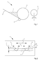
- Figure 1 shows a detail of a printing machine 1 for printing sheets in offset printing.
- the detail shows an inking unit, which comprises a paint box 2 with a ink fountain roller 4 and a lifting roller 5.
- the ink fountain 2 receives a wedge-shaped supply of printing ink 3 and is equipped with a metering device 6, which is subdivided into individually controllable ink zones over the printing width.
- the squeegee roller 5 periodically applies to the ink fountain roller 4 to remove the ink therefrom.
- the ink fountain roller 4 is circumferentially with a provided macroscopic cell structure, which is shown in Figure 2 in enlarged section.
- Figure 2 shows that the peripheral surface of the ink fountain roller 4 forms a support surface 7, which consists of web-like webs 8 merging into one another.
- cells 9 z According to a grid. B. introduced by laser engraving.
- the grid 11 has a grid width corresponding to a center distance A of the wells 9.
- the center distance A can, for. B. 400 microns to 900 microns.
- the wells 9 each have an opening 10 whose diameter D may be 200 microns to 300 microns.
- the depth t of the respective well 9 is at least 10 microns.
- the center distance A is about 500 microns, the cell spacing S about 280 microns, the diameter D about 250 microns, wherein the depth t about 15 ⁇ m.
- the introduced into the ink fountain roller 4 cups 9 prevent clogging of between the ink fountain roller 4 and the metering device 6 or - in the case of an inserted between the ink fountain roller 4 and the metering device 6 ink fountain pen - between ebendon ink fountain film and the ink fountain roller 4 existing color gap by dirt and ink particles ,
- the cups 9 prevent clumping of the ink 3 in the ink gap and reduce the wear of the ink fountain roller 4, which would otherwise cause the dirt or paint particles or lumps.
- the ink fountain roller 4 is particularly well suited to the case where the ink 3 is a UV ink.
Landscapes
- Inking, Control Or Cleaning Of Printing Machines (AREA)
Abstract
Description
- Vorliegende Erfindung betrifft einen Farbkasten einer Druckmaschine und eine Farbkastenwalze für einen solchen Farbkasten.
- Es gibt zwei Typen von Farbkästen. Bei dem einen bilden ein oder mehrere Dosierelemente, z. B. ein Farbmesser oder mehrere Farbschieber, zusammen mit der Farbkastenwalze einen Dosierspalt. Bei dem anderen Typ bildet eine Folie, welche sich zwischen den Dosierelementen und der Farbkastenwalze befindet, zusammen mit letzterer den Dosierspalt. Unabhängig vom Farbkastentyp sind die den Dosierspalt bildenden Bauteile, welche mit der Druckfarbe in Kontakt kommen, bei der Verarbeitung von stark abrasiv wirkenden Druckfarben einem übermäßigen Verschleiß ausgesetzt. Stark abrasiv wirkende Druckfarben sind erfahrungsgemäß UV-Farben, Deckweiß-Farben und Mattlacke. Für die Abrasionswirkung ursächlich ist beispielsweise bei UV-Farben deren Neigung, infolge des im Dosierspalt wirksamen hydrodynamischen Druckes zu polymerisieren und dabei in Partikelform auszuhärten. Die Partikel können derart anwachsen, dass sie sich im Eingang des Dosierspalts zu einer abrasiven Schicht aufstauen.
- In
DE 199 14 179 A1 ist eine Farbkastenfolie mit drahtförmigen Körpern beschrieben, welche den Verschleißwiderstand erhöhen. Bei einem Ausführungsbeispiel dieser Folie sind die drahtförmigen Körper auf einer Trägerlage befestigt und mit einer Decklage abgedeckt, derart, dass zwischen den drahtförmigen Körpern linienförmige Rillen verlaufen. - Der Erfindung liegt die Aufgabe zugrunde, einen auch bei Verarbeitung von stark abrasiven Druckfarben hinreichend verschleißbeständigen Farbkasten zu schaffen.
- Diese Aufgabe wird durch einen Farbkasten mit den Merkmalen des Anspruchs 1 gelöst. Der erfindungsgemäße Farbkasten einer Druckmaschine umfasst ein Bauteil mit einer Tragfläche zum Tragen der Druckfarbe und in die Tragfläche eingebrachten Näpfchen.
- Es hat sich in Versuchen herausgestellt, dass durch die Näpfchen Partikel, wie die erwähnten UV-Farben-Partikel, aus dem Dosierspalt gespült werden. Das den Dosierspalt begrenzende Bauteil, z. B. eine Farbkastenfolie oder ein Dosierelement, ist nicht mehr der Schleifwirkung sich im Dosierspalt stauender Partikel ausgesetzt, wodurch sich die Standzeit verlängert.
- Die Öffnung des jeweiligen Näpfchens hat, im Gegensatz zu einer linienförmigen Rille, einen rundum in sich geschlossenen Rand.
- In den Unteransprüchen sind Weiterbildungen des erfindungsgemäßen Farbkastens genannt.
- Bei einer Weiterbildung bildet die Tragfläche zwischen den Näpfchen liegende Stege, die einen höheren Flächenanteil als Näpfchen einnehmen. Demgemäß ist pro Flächeneinheit die Summe der Flächen der Stege größer als die Summe der Fläche der Näpfchen.
- Bei einer weiteren Weiterbildung weisen die Näpfchen eine Öffnung mit einer Öffnungsweite auf, die weniger als 1 Millimeter beträgt. Bei der Öffnungsweite kann es sich um die Seitenlänge eines Quadrats handeln, wenn das jeweilige Näpfchen die Form einer Hohlpyramide hat und die Öffnung demzufolge quadratisch ist.
- Bei einer weiteren Weiterbildung ist die Öffnung rund und ist die Öffnungsweite ein Durchmesser. Diese Geometrie ist gegeben, wenn das jeweilige Näpfchen die Form einer Kalotte oder eines Hohlkegels hat.
- Bei einer weiteren Weiterbildung weisen die Näpfchen eine Tiefe auf, die höchstens 50 % der Öffnungsweite beträgt. Demgemäß ist das jeweilige Näpfchen höchstens halb so tief wie breit.
- Bei einer weiteren Weiterbildung sind die Näpfchen in einem regelmäßigen Raster angeordnet. Beispielsweise können die Näpfchen schachbrettmusterartig angeordnet sein.
- Bei einer weiteren Weiterbildung ist das die Näpfchenstruktur aufweisende Bauteil eine Farbkastenwalze. Vorzugsweise handelt es sich bei der Farbkastenwalze um eine solche, die periodisch von einer Heberwalze kontaktiert wird.
- Zur Erfindung gehören auch eine Farbkastenwalze, welche eine Tragfläche zum Tragen der Druckfarbe und in die Tragfläche eingebrachte Näpfchen aufweist, und eine Druckmaschine, welche mit einem erfindungsgemäß oder einer der Weiterbildungen entsprechend ausgebildeten Farbkasten ausgestattet ist.
- Gemäß einer Weiterbildung der Farbkastenwalze bilden die darin eingebrachten Näpfchen ein regelmäßiges Raster. Abweichend von dieser bevorzugten Weiterbildung können die Näpfchen aber auch in unregelmäßiger bzw. stochastischer Verteilung in die Umfangsoberfläche der Farbkastenwalze eingebracht sein.
- Weitere konstruktiv und funktionell vorteilhafte Weiterbildungen der Erfindung ergeben sich aus der nachfolgenden Beschreibung eines bevorzugten Ausführungsbeispiels und der dazugehörigen Zeichnung.
- In dieser zeigt:
- Figur 1
- einen Farbkasten mit einer Farbkastenwalze und
- Figur 2
- eine Oberflächenstruktur der Farbkastenwalze aus Figur 1.
- Figur 1 zeigt ausschnittsweise eine Druckmaschine 1 zum Bedrucken von Bogen im Offsetdruck. Der Ausschnitt zeigt ein Farbwerk, welches einen Farbkasten 2 mit einer Farbkastenwalze 4 und eine Heberwalze 5 umfasst. Der Farbkasten 2 nimmt einen keilförmigen Vorrat an Druckfarbe 3 auf und ist mit einer Dosiereinrichtung 6 ausgestattet, die in individuell steuerbare Farbzonen über die Druckbreite unterteilt ist. Während des Druckbetriebs legt sich die Heberwalze 5 periodisch an die Farbkastenwalze 4, um von dieser die Druckfarbe abzunehmen. Die Farbkastenwalze 4 ist umfangsseitig mit einer makroskopischen Näpfchenstruktur versehen, die in Figur 2 im vergrößerten Schnitt dargestellt ist.
- Figur 2 zeigt, dass die Umfangsfläche der Farbkastenwalze 4 eine Tragfläche 7 bildet, welche aus maschenartig ineinander übergehenden Stegen 8 besteht. In die Umfangsfläche sind entsprechend einem Raster 11 Näpfchen 9 z. B. per Lasergravur eingebracht. Das Raster 11 hat eine Rasterweite entsprechend einem Mittenabstand A der Näpfchen 9. Der Mittenabstand A kann z. B. 400 µm bis 900 µm betragen. Ein von Näpfchen zu Nachbarnäpfchen zu messender Näpfchenabstand S, welcher der Breite der Stege 8 entspricht, kann z. B. 200 µm bis 600 µm betragen. Die Näpfchen 9 haben jeweils eine Öffnung 10, deren Durchmesser D 200 µm bis 300 µm betragen kann. Die Tiefe t des jeweiligen Näpfchens 9 beträgt mindestens 10 µm.
- Beispielsweise beträgt bei einem ca. 76 % betragenden Trag- oder Flächenanteil der Stege 8 oder Tragfläche 7 der Mittenabstand A ca. 500 µm, der Näpfchenabstand S ca. 280 µm, der Durchmesser D ca. 250 µm, wobei die Tiefe t ca. 15 µm beträgt.
- Bevorzugt wird eine Variante mit einem ca. 88 % betragenden Trag- oder Flächenanteil der Stege 8 oder Tragfläche 7, wobei der Mittenabstand A ca. 770 µm, der Näpfchenabstand S ca. 560 µm, der Durchmesser D ca. 275 µm und die Tiefe t ca. 15 µm beträgt.
- Die in die Farbkastenwalze 4 eingebrachten Näpfchen 9 verhindern ein Zusetzen des zwischen der Farbkastenwalze 4 und der Dosiereinrichtung 6 oder - im Falle einer zwischen der Farbkastenwalze 4 und der Dosiereinrichtung 6 eingefügten Farbkastenfolie - zwischen ebendieser Farbkastenfolie und der Farbkastenwalze 4 vorhandenen Farbspalts durch Schmutz- und Farbpartikel. Die Näpfchen 9 verhindern ein Verklumpen der Druckfarbe 3 im Farbspalt und reduzieren den Verschleiß der Farbkastenwalze 4, welchen die Schmutz-oder Farbpartikel oder -klumpen sonst bewirken würden. Dadurch erhöht sich die Reproduziergenauigkeit der Einstellung der Dosiereinrichtung 6 und werden Qualitätsschwankungen des Druckbilds verringert. Die Farbkastenwalze 4 ist besonders gut für den Fall geeignet, in welchem es sich bei der Druckfarbe 3 um eine UV-Farbe handelt.
-
- 1
- Druckmaschine
- 2
- Farbkasten
- 3
- Druckfarbe
- 4
- Farbkastenwalze
- 5
- Heberwalze
- 6
- Dosiereinrichtung
- 7
- Tragfläche
- 8
- Steg
- 9
- Näpfchen
- 10
- Öffnung
- 11
- Raster
- A
- Mittenabstand
- D
- Durchmesser
- S
- Näpfchenabstand
- t
- Tiefe
Claims (10)
- Farbkasten (2) einer Druckmaschine (1), umfassend ein Bauteil mit einer Tragfläche (7) zum Tragen der Druckfarbe (3) und in die Tragfläche (7) eingebrachten Näpfchen (9).
- Farbkasten nach Anspruch 1,
wobei die Tragfläche (7) zwischen den Näpfchen (9) liegende Stege (8) bildet, die einen höheren Flächenanteil als die Näpfchen (9) einnehmen. - Farbkasten nach Anspruch 1 oder 2,
wobei die Näpfchen (9) eine Öffnung (10) mit einer Öffnungsweite aufweisen, die weniger als 1 Millimeter beträgt. - Farbkasten nach Anspruch 3,
wobei die Öffnung (10) rund ist und die Öffnungsweite ein Durchmesser (D) ist. - Farbkasten nach Anspruch 3 oder 4,
wobei die Näpfchen (9) eine Tiefe (t) aufweisen, die höchstens 50% der Öffnungsweite beträgt. - Farbkasten nach einem der Anspruch 1 bis 5,
wobei die Näpfchen (9) in einem regelmäßigen Raster (11) angeordnet sind. - Farbkasten nach einem der Ansprüche 1 bis 6,
wobei das Bauteil eine Farbkastenwalze (4) ist. - Farbkastenwalze (4) für einen Farbkasten (2) einer Druckmaschine (1),
wobei die Farbkastenwalze (4) eine Tragfläche (7) zum Tragen der Druckfarbe (3) und in die Tragfläche (7) eingebrachte Näpfchen (9) aufweist. - Farbkastenwalze nach Anspruch 8,
wobei die Näpfchen (9) in einem regelmäßigen Raster (11) angeordnet sind. - Druckmaschine (1), mit einem Farbkasten (2) nach einem der Ansprüche 1 bis 7.
Applications Claiming Priority (1)
| Application Number | Priority Date | Filing Date | Title |
|---|---|---|---|
| DE102006048487A DE102006048487A1 (de) | 2006-10-11 | 2006-10-11 | Farbkasten einer Druckmaschine |
Publications (3)
| Publication Number | Publication Date |
|---|---|
| EP1911587A2 true EP1911587A2 (de) | 2008-04-16 |
| EP1911587A3 EP1911587A3 (de) | 2010-07-21 |
| EP1911587B1 EP1911587B1 (de) | 2011-11-09 |
Family
ID=39092747
Family Applications (1)
| Application Number | Title | Priority Date | Filing Date |
|---|---|---|---|
| EP07116204A Active EP1911587B1 (de) | 2006-10-11 | 2007-09-12 | Druckmaschine |
Country Status (6)
| Country | Link |
|---|---|
| US (1) | US8146493B2 (de) |
| EP (1) | EP1911587B1 (de) |
| JP (2) | JP2008094096A (de) |
| CN (1) | CN101161456B (de) |
| AT (1) | ATE532635T1 (de) |
| DE (1) | DE102006048487A1 (de) |
Cited By (1)
| Publication number | Priority date | Publication date | Assignee | Title |
|---|---|---|---|---|
| CN108569026A (zh) * | 2018-07-02 | 2018-09-25 | 河南金宏印业有限公司 | 环保型对辊式印刷机 |
Families Citing this family (2)
| Publication number | Priority date | Publication date | Assignee | Title |
|---|---|---|---|---|
| JP4586550B2 (ja) * | 2004-01-29 | 2010-11-24 | 旭硝子株式会社 | 平板ディスプレイ用外囲器およびそれを用いた平板ディスプレイ |
| US20150128821A1 (en) * | 2013-11-13 | 2015-05-14 | Stolle Machinery Company, Llc | Fountain blade assembly for can decorator machine ink station assembly |
Citations (1)
| Publication number | Priority date | Publication date | Assignee | Title |
|---|---|---|---|---|
| DE19914179A1 (de) | 1998-04-23 | 1999-11-11 | Heidelberger Druckmasch Ag | Vorrichtung zur Farbdosierung in einer Druckmaschine |
Family Cites Families (22)
| Publication number | Priority date | Publication date | Assignee | Title |
|---|---|---|---|---|
| DE120833C (de) | ||||
| US2393529A (en) * | 1940-01-19 | 1946-01-22 | Distr Of Columbia Paper Mills | Apparatus for applying coatings to web material |
| US2514653A (en) * | 1949-05-02 | 1950-07-11 | Stephen A Lerch | Ink fountain divider |
| JPS4726562Y1 (de) * | 1968-09-09 | 1972-08-16 | ||
| DE1918987B2 (de) * | 1969-04-15 | 1971-06-16 | Roland Offsetmaschinenfabrik Faber & Schleicher Ag, 6050 Offenbach | Duktorwalze fuer ein farbwerk von druckmaschinen |
| DD120833A1 (de) * | 1975-05-15 | 1976-07-05 | ||
| DD200664A1 (de) * | 1981-08-20 | 1983-06-01 | Matthias Schuetze | Vorrichtung zur farbdosierung in farbwerken von druckmaschinen |
| DE3241124A1 (de) * | 1982-11-06 | 1984-05-10 | Koenig & Bauer AG, 8700 Würzburg | Farbabteilkeil in einem farbkasten einer rotationsdruckmaschine |
| DE3543146A1 (de) * | 1985-12-06 | 1987-09-24 | Otto Hein | Vorrichtung zur partiellen farbdosierung an farbwerken von druckmaschinen |
| JPS6394728U (de) * | 1986-12-11 | 1988-06-18 | ||
| JPH0795194B2 (ja) * | 1989-05-19 | 1995-10-11 | 大日本スクリーン製造株式会社 | グラビア印刷版 |
| DE4115026A1 (de) * | 1991-05-08 | 1992-11-12 | Man Miller Druckmasch | Kurzfarbwerk fuer bogenoffset oder rollenoffset |
| DE4137337A1 (de) * | 1991-11-13 | 1993-05-19 | Sengewald Karl H Gmbh | Hochdruckverfahren und auftragsvorrichtung zu seiner durchfuehrung |
| DE19614191A1 (de) * | 1996-04-10 | 1997-10-16 | Heidelberger Druckmasch Ag | Farbdosiereinrichtung für Farbwerke von Druckmaschinen |
| DE19717524C2 (de) * | 1997-04-25 | 2002-04-04 | Roland Man Druckmasch | Farbwerk für eine Druckmaschine |
| DE19757897C1 (de) * | 1997-12-24 | 1999-07-22 | Koenig & Bauer Ag | Anordnung für ein Farbwerk einer Rotationsdruckmaschine |
| JP2001162769A (ja) * | 1999-12-13 | 2001-06-19 | Goss Graphic Systems Japan Corp | 印刷機のインキ供給装置 |
| DE10158485A1 (de) * | 2001-01-12 | 2002-07-18 | Heidelberger Druckmasch Ag | Farbwerk in einer Druckmaschine |
| DE20320598U1 (de) * | 2003-08-16 | 2004-11-18 | Man Roland Druckmaschinen Ag | Dosiereinrichtung für Farben und Lacke |
| CN1261300C (zh) * | 2003-12-27 | 2006-06-28 | 潍坊华光精工设备有限公司 | 印刷机分区墨斗 |
| JP4958391B2 (ja) * | 2004-07-05 | 2012-06-20 | リョービ株式会社 | 印刷機およびインキ移しローラの制御方法 |
| US20070261577A1 (en) * | 2006-04-26 | 2007-11-15 | Burrow William J | Printing roll with dead band helical pattern |
-
2006
- 2006-10-11 DE DE102006048487A patent/DE102006048487A1/de not_active Withdrawn
-
2007
- 2007-09-12 EP EP07116204A patent/EP1911587B1/de active Active
- 2007-09-12 AT AT07116204T patent/ATE532635T1/de active
- 2007-10-05 JP JP2007261784A patent/JP2008094096A/ja active Pending
- 2007-10-10 CN CN200710180137.XA patent/CN101161456B/zh active Active
- 2007-10-11 US US11/870,495 patent/US8146493B2/en not_active Expired - Fee Related
-
2012
- 2012-08-30 JP JP2012005308U patent/JP3179633U/ja not_active Expired - Lifetime
Patent Citations (1)
| Publication number | Priority date | Publication date | Assignee | Title |
|---|---|---|---|---|
| DE19914179A1 (de) | 1998-04-23 | 1999-11-11 | Heidelberger Druckmasch Ag | Vorrichtung zur Farbdosierung in einer Druckmaschine |
Cited By (1)
| Publication number | Priority date | Publication date | Assignee | Title |
|---|---|---|---|---|
| CN108569026A (zh) * | 2018-07-02 | 2018-09-25 | 河南金宏印业有限公司 | 环保型对辊式印刷机 |
Also Published As
| Publication number | Publication date |
|---|---|
| ATE532635T1 (de) | 2011-11-15 |
| JP3179633U (ja) | 2012-11-08 |
| US20080250957A1 (en) | 2008-10-16 |
| EP1911587A3 (de) | 2010-07-21 |
| CN101161456B (zh) | 2010-12-01 |
| EP1911587B1 (de) | 2011-11-09 |
| CN101161456A (zh) | 2008-04-16 |
| US8146493B2 (en) | 2012-04-03 |
| DE102006048487A1 (de) | 2008-04-17 |
| JP2008094096A (ja) | 2008-04-24 |
Similar Documents
| Publication | Publication Date | Title |
|---|---|---|
| EP1556218B1 (de) | Rakeleinrichtungen einer bahnerzeugenden oder -verarbeitenden maschine | |
| DE69205454T2 (de) | Langlebiges System zur variablen Übertragung von Druckfarben sowie Zylinder für ein Drucksystem ohne Farbmesser. | |
| DE2414657A1 (de) | Einrichtung zum auftragen fluessiger oder pastoeser massen auf eine warenbahn | |
| EP0280140B1 (de) | Verfahren zum Übertragen von Farbe mit einer Rasterwalze | |
| EP1911587B1 (de) | Druckmaschine | |
| DE19859437A1 (de) | Farbwerk | |
| DE3219786A1 (de) | Vorrichtung zum dosierenden auftragen und dosierenden entfernen von druckfarbe auf bzw. von einer walze, insbes. fuer eine flexodruckmaschine | |
| DE68922685T2 (de) | Farbwerkzylinder für eine Druckmaschine und Herstellungsverfahren desselben. | |
| DE102009034237A1 (de) | Vorrichtung zum berührungslosen Übertragen von Druckflüssigkeit | |
| DE102019103789A1 (de) | Druckwerk und Druckmaschine mit einem Druckwerk | |
| EP4013615B1 (de) | Tiefdruckwerk | |
| DE102018101295A1 (de) | Verfahren und Vorrichtung zum Bedrucken eines Aufzeichnungsträgers mit einem Beschichtungsstoff und entsprechendes Drucksystem | |
| DE2942733C2 (de) | Farbwerk für Offset-Rotationsdruckmaschinen | |
| DE68922568T2 (de) | Farbzuführvorrichtung für eine Druckmaschine. | |
| WO2021180374A1 (de) | Sicherheitselement, sicherheitsdokument mit einem sicherheitselement sowie vorrichtung und verfahren zur herstellung eines sicherheitselementes | |
| DE102013206588A1 (de) | Verfahren und Vorrichtung zum Bedrucken eines Substrats | |
| EP4175829B1 (de) | Farbwerk einer rotationsdruckmaschine | |
| EP0909645A2 (de) | Transportrommel in Rotationsdruckmaschinen | |
| DE10028476A1 (de) | Rakelvorrichtung | |
| DE68919830T2 (de) | Hydrophobe oleophile mikroporöse Farbwalzen. | |
| DE10208055B4 (de) | Verfahren und Vorrichtung zum Bedrucken eines Bedruckstoffes | |
| DE102024112333A1 (de) | Druckwerk zum Bedrucken von Substrat nach einem Tiefdruckverfahren | |
| DE102024112330A1 (de) | Druckwerk zum Bedrucken von Substrat nach einem Tiefdruckverfahren sowie ein Verfahren zum Betreiben eines nach einem Tiefdruckverfahren arbeitenden Druckwerks | |
| DE102024112331A1 (de) | Druckwerk zum Bedrucken von Substrat nach einem Tiefdruckverfahren | |
| DE102022126586A1 (de) | 3D-Druck-Verfahren und 3D-Drucker |
Legal Events
| Date | Code | Title | Description |
|---|---|---|---|
| PUAI | Public reference made under article 153(3) epc to a published international application that has entered the european phase |
Free format text: ORIGINAL CODE: 0009012 |
|
| AK | Designated contracting states |
Kind code of ref document: A2 Designated state(s): AT BE BG CH CY CZ DE DK EE ES FI FR GB GR HU IE IS IT LI LT LU LV MC MT NL PL PT RO SE SI SK TR |
|
| AX | Request for extension of the european patent |
Extension state: AL BA HR MK RS |
|
| PUAL | Search report despatched |
Free format text: ORIGINAL CODE: 0009013 |
|
| AK | Designated contracting states |
Kind code of ref document: A3 Designated state(s): AT BE BG CH CY CZ DE DK EE ES FI FR GB GR HU IE IS IT LI LT LU LV MC MT NL PL PT RO SE SI SK TR |
|
| AX | Request for extension of the european patent |
Extension state: AL BA HR MK RS |
|
| 17P | Request for examination filed |
Effective date: 20110121 |
|
| 17Q | First examination report despatched |
Effective date: 20110228 |
|
| AKX | Designation fees paid |
Designated state(s): AT BE BG CH CY CZ DE DK EE ES FI FR GB GR HU IE IS IT LI LT LU LV MC MT NL PL PT RO SE SI SK TR |
|
| GRAP | Despatch of communication of intention to grant a patent |
Free format text: ORIGINAL CODE: EPIDOSNIGR1 |
|
| RIC1 | Information provided on ipc code assigned before grant |
Ipc: B41F 31/26 20060101ALI20110509BHEP Ipc: B41F 31/04 20060101AFI20110509BHEP |
|
| RTI1 | Title (correction) |
Free format text: PRINTING PRESS |
|
| GRAS | Grant fee paid |
Free format text: ORIGINAL CODE: EPIDOSNIGR3 |
|
| GRAA | (expected) grant |
Free format text: ORIGINAL CODE: 0009210 |
|
| AK | Designated contracting states |
Kind code of ref document: B1 Designated state(s): AT BE BG CH CY CZ DE DK EE ES FI FR GB GR HU IE IS IT LI LT LU LV MC MT NL PL PT RO SE SI SK TR |
|
| REG | Reference to a national code |
Ref country code: GB Ref legal event code: FG4D Free format text: NOT ENGLISH |
|
| REG | Reference to a national code |
Ref country code: CH Ref legal event code: EP |
|
| REG | Reference to a national code |
Ref country code: IE Ref legal event code: FG4D Free format text: LANGUAGE OF EP DOCUMENT: GERMAN |
|
| REG | Reference to a national code |
Ref country code: DE Ref legal event code: R096 Ref document number: 502007008627 Country of ref document: DE Effective date: 20120119 |
|
| REG | Reference to a national code |
Ref country code: NL Ref legal event code: VDEP Effective date: 20111109 |
|
| LTIE | Lt: invalidation of european patent or patent extension |
Effective date: 20111109 |
|
| PG25 | Lapsed in a contracting state [announced via postgrant information from national office to epo] |
Ref country code: IS Free format text: LAPSE BECAUSE OF FAILURE TO SUBMIT A TRANSLATION OF THE DESCRIPTION OR TO PAY THE FEE WITHIN THE PRESCRIBED TIME-LIMIT Effective date: 20120309 Ref country code: LT Free format text: LAPSE BECAUSE OF FAILURE TO SUBMIT A TRANSLATION OF THE DESCRIPTION OR TO PAY THE FEE WITHIN THE PRESCRIBED TIME-LIMIT Effective date: 20111109 |
|
| PG25 | Lapsed in a contracting state [announced via postgrant information from national office to epo] |
Ref country code: NL Free format text: LAPSE BECAUSE OF FAILURE TO SUBMIT A TRANSLATION OF THE DESCRIPTION OR TO PAY THE FEE WITHIN THE PRESCRIBED TIME-LIMIT Effective date: 20111109 Ref country code: PT Free format text: LAPSE BECAUSE OF FAILURE TO SUBMIT A TRANSLATION OF THE DESCRIPTION OR TO PAY THE FEE WITHIN THE PRESCRIBED TIME-LIMIT Effective date: 20120309 Ref country code: SE Free format text: LAPSE BECAUSE OF FAILURE TO SUBMIT A TRANSLATION OF THE DESCRIPTION OR TO PAY THE FEE WITHIN THE PRESCRIBED TIME-LIMIT Effective date: 20111109 Ref country code: LV Free format text: LAPSE BECAUSE OF FAILURE TO SUBMIT A TRANSLATION OF THE DESCRIPTION OR TO PAY THE FEE WITHIN THE PRESCRIBED TIME-LIMIT Effective date: 20111109 Ref country code: GR Free format text: LAPSE BECAUSE OF FAILURE TO SUBMIT A TRANSLATION OF THE DESCRIPTION OR TO PAY THE FEE WITHIN THE PRESCRIBED TIME-LIMIT Effective date: 20120210 Ref country code: SI Free format text: LAPSE BECAUSE OF FAILURE TO SUBMIT A TRANSLATION OF THE DESCRIPTION OR TO PAY THE FEE WITHIN THE PRESCRIBED TIME-LIMIT Effective date: 20111109 Ref country code: PL Free format text: LAPSE BECAUSE OF FAILURE TO SUBMIT A TRANSLATION OF THE DESCRIPTION OR TO PAY THE FEE WITHIN THE PRESCRIBED TIME-LIMIT Effective date: 20111109 |
|
| REG | Reference to a national code |
Ref country code: IE Ref legal event code: FD4D |
|
| PG25 | Lapsed in a contracting state [announced via postgrant information from national office to epo] |
Ref country code: CY Free format text: LAPSE BECAUSE OF FAILURE TO SUBMIT A TRANSLATION OF THE DESCRIPTION OR TO PAY THE FEE WITHIN THE PRESCRIBED TIME-LIMIT Effective date: 20111109 |
|
| PG25 | Lapsed in a contracting state [announced via postgrant information from national office to epo] |
Ref country code: IE Free format text: LAPSE BECAUSE OF FAILURE TO SUBMIT A TRANSLATION OF THE DESCRIPTION OR TO PAY THE FEE WITHIN THE PRESCRIBED TIME-LIMIT Effective date: 20111109 Ref country code: SK Free format text: LAPSE BECAUSE OF FAILURE TO SUBMIT A TRANSLATION OF THE DESCRIPTION OR TO PAY THE FEE WITHIN THE PRESCRIBED TIME-LIMIT Effective date: 20111109 Ref country code: CZ Free format text: LAPSE BECAUSE OF FAILURE TO SUBMIT A TRANSLATION OF THE DESCRIPTION OR TO PAY THE FEE WITHIN THE PRESCRIBED TIME-LIMIT Effective date: 20111109 Ref country code: DK Free format text: LAPSE BECAUSE OF FAILURE TO SUBMIT A TRANSLATION OF THE DESCRIPTION OR TO PAY THE FEE WITHIN THE PRESCRIBED TIME-LIMIT Effective date: 20111109 Ref country code: BG Free format text: LAPSE BECAUSE OF FAILURE TO SUBMIT A TRANSLATION OF THE DESCRIPTION OR TO PAY THE FEE WITHIN THE PRESCRIBED TIME-LIMIT Effective date: 20120209 Ref country code: EE Free format text: LAPSE BECAUSE OF FAILURE TO SUBMIT A TRANSLATION OF THE DESCRIPTION OR TO PAY THE FEE WITHIN THE PRESCRIBED TIME-LIMIT Effective date: 20111109 |
|
| PG25 | Lapsed in a contracting state [announced via postgrant information from national office to epo] |
Ref country code: IT Free format text: LAPSE BECAUSE OF FAILURE TO SUBMIT A TRANSLATION OF THE DESCRIPTION OR TO PAY THE FEE WITHIN THE PRESCRIBED TIME-LIMIT Effective date: 20111109 Ref country code: RO Free format text: LAPSE BECAUSE OF FAILURE TO SUBMIT A TRANSLATION OF THE DESCRIPTION OR TO PAY THE FEE WITHIN THE PRESCRIBED TIME-LIMIT Effective date: 20111109 |
|
| PLBE | No opposition filed within time limit |
Free format text: ORIGINAL CODE: 0009261 |
|
| STAA | Information on the status of an ep patent application or granted ep patent |
Free format text: STATUS: NO OPPOSITION FILED WITHIN TIME LIMIT |
|
| 26N | No opposition filed |
Effective date: 20120810 |
|
| PGFP | Annual fee paid to national office [announced via postgrant information from national office to epo] |
Ref country code: GB Payment date: 20120925 Year of fee payment: 6 |
|
| REG | Reference to a national code |
Ref country code: DE Ref legal event code: R097 Ref document number: 502007008627 Country of ref document: DE Effective date: 20120810 |
|
| PGFP | Annual fee paid to national office [announced via postgrant information from national office to epo] |
Ref country code: FR Payment date: 20121011 Year of fee payment: 6 |
|
| BERE | Be: lapsed |
Owner name: HEIDELBERGER DRUCKMASCHINEN A.G. Effective date: 20120930 |
|
| PG25 | Lapsed in a contracting state [announced via postgrant information from national office to epo] |
Ref country code: MC Free format text: LAPSE BECAUSE OF NON-PAYMENT OF DUE FEES Effective date: 20120930 Ref country code: ES Free format text: LAPSE BECAUSE OF FAILURE TO SUBMIT A TRANSLATION OF THE DESCRIPTION OR TO PAY THE FEE WITHIN THE PRESCRIBED TIME-LIMIT Effective date: 20120220 |
|
| REG | Reference to a national code |
Ref country code: CH Ref legal event code: PL |
|
| PG25 | Lapsed in a contracting state [announced via postgrant information from national office to epo] |
Ref country code: FI Free format text: LAPSE BECAUSE OF FAILURE TO SUBMIT A TRANSLATION OF THE DESCRIPTION OR TO PAY THE FEE WITHIN THE PRESCRIBED TIME-LIMIT Effective date: 20111109 |
|
| PG25 | Lapsed in a contracting state [announced via postgrant information from national office to epo] |
Ref country code: BE Free format text: LAPSE BECAUSE OF NON-PAYMENT OF DUE FEES Effective date: 20120930 Ref country code: CH Free format text: LAPSE BECAUSE OF NON-PAYMENT OF DUE FEES Effective date: 20120930 Ref country code: LI Free format text: LAPSE BECAUSE OF NON-PAYMENT OF DUE FEES Effective date: 20120930 |
|
| REG | Reference to a national code |
Ref country code: AT Ref legal event code: MM01 Ref document number: 532635 Country of ref document: AT Kind code of ref document: T Effective date: 20120912 |
|
| PG25 | Lapsed in a contracting state [announced via postgrant information from national office to epo] |
Ref country code: MT Free format text: LAPSE BECAUSE OF FAILURE TO SUBMIT A TRANSLATION OF THE DESCRIPTION OR TO PAY THE FEE WITHIN THE PRESCRIBED TIME-LIMIT Effective date: 20111109 |
|
| PG25 | Lapsed in a contracting state [announced via postgrant information from national office to epo] |
Ref country code: AT Free format text: LAPSE BECAUSE OF NON-PAYMENT OF DUE FEES Effective date: 20120912 |
|
| PG25 | Lapsed in a contracting state [announced via postgrant information from national office to epo] |
Ref country code: TR Free format text: LAPSE BECAUSE OF FAILURE TO SUBMIT A TRANSLATION OF THE DESCRIPTION OR TO PAY THE FEE WITHIN THE PRESCRIBED TIME-LIMIT Effective date: 20111109 |
|
| GBPC | Gb: european patent ceased through non-payment of renewal fee |
Effective date: 20130912 |
|
| PG25 | Lapsed in a contracting state [announced via postgrant information from national office to epo] |
Ref country code: LU Free format text: LAPSE BECAUSE OF NON-PAYMENT OF DUE FEES Effective date: 20120912 |
|
| REG | Reference to a national code |
Ref country code: FR Ref legal event code: ST Effective date: 20140530 |
|
| PG25 | Lapsed in a contracting state [announced via postgrant information from national office to epo] |
Ref country code: HU Free format text: LAPSE BECAUSE OF FAILURE TO SUBMIT A TRANSLATION OF THE DESCRIPTION OR TO PAY THE FEE WITHIN THE PRESCRIBED TIME-LIMIT Effective date: 20070912 Ref country code: GB Free format text: LAPSE BECAUSE OF NON-PAYMENT OF DUE FEES Effective date: 20130912 |
|
| PG25 | Lapsed in a contracting state [announced via postgrant information from national office to epo] |
Ref country code: FR Free format text: LAPSE BECAUSE OF NON-PAYMENT OF DUE FEES Effective date: 20130930 |
|
| REG | Reference to a national code |
Ref country code: DE Ref legal event code: R081 Ref document number: 502007008627 Country of ref document: DE Owner name: HEIDELBERGER DRUCKMASCHINEN AG, DE Free format text: FORMER OWNER: HEIDELBERGER DRUCKMASCHINEN AKTIENGESELLSCHAFT, 69115 HEIDELBERG, DE |
|
| P01 | Opt-out of the competence of the unified patent court (upc) registered |
Effective date: 20230425 |
|
| PGFP | Annual fee paid to national office [announced via postgrant information from national office to epo] |
Ref country code: DE Payment date: 20250930 Year of fee payment: 19 |