EP1910698B1 - Roue libre a rouleaux/douille pourvue d'une bague exterieure massive - Google Patents
Roue libre a rouleaux/douille pourvue d'une bague exterieure massive Download PDFInfo
- Publication number
- EP1910698B1 EP1910698B1 EP06776175A EP06776175A EP1910698B1 EP 1910698 B1 EP1910698 B1 EP 1910698B1 EP 06776175 A EP06776175 A EP 06776175A EP 06776175 A EP06776175 A EP 06776175A EP 1910698 B1 EP1910698 B1 EP 1910698B1
- Authority
- EP
- European Patent Office
- Prior art keywords
- sleeve
- outer ring
- roller freewheel
- freewheel according
- clamping ramps
- Prior art date
- Legal status (The legal status is an assumption and is not a legal conclusion. Google has not performed a legal analysis and makes no representation as to the accuracy of the status listed.)
- Active
Links
- 239000007787 solid Substances 0.000 title claims abstract description 7
- 229910052751 metal Inorganic materials 0.000 claims description 5
- 239000002184 metal Substances 0.000 claims description 5
- 229920003023 plastic Polymers 0.000 claims description 3
- 239000004033 plastic Substances 0.000 claims description 3
- 238000004519 manufacturing process Methods 0.000 description 9
- 241000209035 Ilex Species 0.000 description 5
- 239000000463 material Substances 0.000 description 3
- 238000003825 pressing Methods 0.000 description 2
- 229910000838 Al alloy Inorganic materials 0.000 description 1
- 229910000861 Mg alloy Inorganic materials 0.000 description 1
- XAGFODPZIPBFFR-UHFFFAOYSA-N aluminium Chemical compound [Al] XAGFODPZIPBFFR-UHFFFAOYSA-N 0.000 description 1
- 230000005540 biological transmission Effects 0.000 description 1
- 238000005266 casting Methods 0.000 description 1
- 238000005520 cutting process Methods 0.000 description 1
- 238000004049 embossing Methods 0.000 description 1
- 238000010438 heat treatment Methods 0.000 description 1
- 238000005304 joining Methods 0.000 description 1
- 229910001092 metal group alloy Inorganic materials 0.000 description 1
- 150000002739 metals Chemical class 0.000 description 1
- 238000012544 monitoring process Methods 0.000 description 1
- 238000000926 separation method Methods 0.000 description 1
- 238000005245 sintering Methods 0.000 description 1
Images


Classifications
-
- F—MECHANICAL ENGINEERING; LIGHTING; HEATING; WEAPONS; BLASTING
- F16—ENGINEERING ELEMENTS AND UNITS; GENERAL MEASURES FOR PRODUCING AND MAINTAINING EFFECTIVE FUNCTIONING OF MACHINES OR INSTALLATIONS; THERMAL INSULATION IN GENERAL
- F16D—COUPLINGS FOR TRANSMITTING ROTATION; CLUTCHES; BRAKES
- F16D41/00—Freewheels or freewheel clutches
- F16D41/06—Freewheels or freewheel clutches with intermediate wedging coupling members between an inner and an outer surface
- F16D41/064—Freewheels or freewheel clutches with intermediate wedging coupling members between an inner and an outer surface the intermediate members wedging by rolling and having a circular cross-section, e.g. balls
- F16D41/066—Freewheels or freewheel clutches with intermediate wedging coupling members between an inner and an outer surface the intermediate members wedging by rolling and having a circular cross-section, e.g. balls all members having the same size and only one of the two surfaces being cylindrical
- F16D41/067—Freewheels or freewheel clutches with intermediate wedging coupling members between an inner and an outer surface the intermediate members wedging by rolling and having a circular cross-section, e.g. balls all members having the same size and only one of the two surfaces being cylindrical and the members being distributed by a separate cage encircling the axis of rotation
-
- F—MECHANICAL ENGINEERING; LIGHTING; HEATING; WEAPONS; BLASTING
- F16—ENGINEERING ELEMENTS AND UNITS; GENERAL MEASURES FOR PRODUCING AND MAINTAINING EFFECTIVE FUNCTIONING OF MACHINES OR INSTALLATIONS; THERMAL INSULATION IN GENERAL
- F16D—COUPLINGS FOR TRANSMITTING ROTATION; CLUTCHES; BRAKES
- F16D1/00—Couplings for rigidly connecting two coaxial shafts or other movable machine elements
- F16D1/06—Couplings for rigidly connecting two coaxial shafts or other movable machine elements for attachment of a member on a shaft or on a shaft-end
- F16D1/08—Couplings for rigidly connecting two coaxial shafts or other movable machine elements for attachment of a member on a shaft or on a shaft-end with clamping hub; with hub and longitudinal key
- F16D1/0852—Couplings for rigidly connecting two coaxial shafts or other movable machine elements for attachment of a member on a shaft or on a shaft-end with clamping hub; with hub and longitudinal key with radial clamping between the mating surfaces of the hub and shaft
-
- F—MECHANICAL ENGINEERING; LIGHTING; HEATING; WEAPONS; BLASTING
- F16—ENGINEERING ELEMENTS AND UNITS; GENERAL MEASURES FOR PRODUCING AND MAINTAINING EFFECTIVE FUNCTIONING OF MACHINES OR INSTALLATIONS; THERMAL INSULATION IN GENERAL
- F16D—COUPLINGS FOR TRANSMITTING ROTATION; CLUTCHES; BRAKES
- F16D2250/00—Manufacturing; Assembly
Definitions
- Sleeve / roller freewheel with an inner and / or outer ring, with the needles or rollers adapted clamping ramps, with a cage and with pressure springs for the needles or rollers, according to the preamble of claim 1.
- a sleeve / roller freewheel for example from DE 1 750 493 A1 known.
- the from the DE 1 750 493 A1 known freewheel has a sleeve which is bent together from a sheet metal strip and connected at their ends, preferably welded.
- the sleeve of the freewheel is inserted with interference fit into a bore of a machine element.
- one-way clutches used a relatively thin-walled, clamping ramps having sleeve in a solid machine part.
- Pinch roller clutches in torque converters are for example in the EP 0 549 824 A1 as well as in the DE 195 32 923 A1 disclosed. In these cases, in which in comparison to application areas in which sleeve freewheels are typically used, high torques are to be transmitted, contact pinch rollers directly a massive outer ring.
- Freewheels for the transmission of large forces are known.
- clamping ramps are usually integrally formed on the inner surface of the outer ring, which are in operative connection with the rollers. It is also possible to arrange clamping ramps on the outer surface of an inner ring.
- the rollers continue to be based on a smooth shaft or a smooth inner ring or on the inner surface of a smooth outer ring.
- the outer rings must have a sufficient thickness for reasons of strength. It is known to produce the outer rings by sintering, although the strength, especially at the clamping ramps does not always meet the requirements. It is also known, in particular to clear the interior with clamping ramps, including, however, consuming tuning measures in the production process are required.
- the surface of the cleared profile is not optimal due to the manufacturing process, it can create a grooved structure, which can increase the risk of breakage.
- the service life of a broaching tool is short.
- the object of the invention is therefore to improve a generic freewheel to the effect that it is simple and inexpensive to manufacture, especially the series production, and that it meets the quality requirements.
- the object of the invention is achieved by a sleeve with molded clamping ramps and by a solid inner or outer ring in or on which the sleeve is attached.
- the sleeve and the ring is fastened by means of press fit together or in one another in an advantageous manner.
- the sleeve may have on at least one side a radially oriented annular shoulder which forms a stop for the cage or the rollers.
- the interior interior or outer ring is on the sleeve-facing surface and the sleeve is smooth or corrugated on the inner or outer ring facing surface, so that a circumferential tight fit between the two components is ensured and a complete support of the sleeve takes place.
- the sleeve made of thin strip material and the clamping ramps are formed by embossing and that the sleeve is formed into a ring, the ends of which are joined together in abutment.
- they can be welded or they can be firmly pressed into the outer ring by the press fit in the outer ring.
- the sleeves can also be made according to the invention by forming or deep drawing, which also thin-walled sleeves may arise in which the clamping ramps are formed.
- the massive inner or outer ring can also be inexpensively manufactured as a simple rotary part, wherein a laterally arranged radially aligned collar can be formed, which is arranged after joining the ring with the sleeve on the side facing away from the annular shoulder of the sleeve.
- the outer or inner ring and the overlap between the sleeve and the support ring, that is the outer or inner ring, are to be dimensioned so that the sleeve is sufficiently supported. Even under load, the limited strength of the sleeve material is to be observed.
- the thickness ratio between the measured in the radial direction of the minimum thickness of the outer or inner ring and the thickness of the sleeve supported by the outer or inner ring, which has the clamping ramps, is at least 5: 1.
- the outer ring is rotationally fixed in a surrounding component, namely in a flange or in a stator of a torque converter used. Regardless of whether the connection between the outer ring of the freewheel and the surrounding component is made by press-fitting or pouring, torques of more than 200 Nm are transmittable.
- materials for the production of the outer ring surrounding component for example, light metals, especially aluminum or magnesium alloys, and plastics are suitable.
- a particular advantage lies in the fact that the bore of the outer ring need not have a raceway quality, in particular can be used without heat treatment.
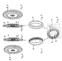
- 1 denotes a sleeve on the inside of clamping ramps 2 are formed.
- the sleeve 1 is made as a sheet metal part without cutting and further has in addition to the clamping ramps 2 a designated 3 annular shoulder, which is directed radially inward.
- needles or rollers Arranged on the clamping ramps 2, not shown needles or rollers are guided in a manner not shown in a cage and are pressed by pressure springs in their respective clamping position.
- the sleeve 1 is, as in FIG. 2 shown, inserted in a designated 4, manufactured as a rotary part outer ring and pressed in, so that they can be fully supported on the outer ring 4, which in turn is pressed into another component, wherein to increase the seat on the outside of the outer ring 4 a corrugation is appropriate. Due to the clamping ramps 2, the sleeve 1 has a non-uniform thickness, also referred to as wall thickness on.
- the outer ring 4 thus prevents relevant deformations of the sleeve 1 under load, the stability of the entire assembly by the not shown further component, which is also made of metal and, for example, a casting , Turning or milled part is further increased.
- FIG. 3 are in addition to the sleeve 1 in this held or integrally formed with this cage 6 visible to which pressure springs 7 are fixed, the pinch rollers 5 permanently act on a force in the direction of its clamping position.
- the arrangement after FIG. 3 thus, with the exception of the outer ring 4 includes all parts of a roller freewheel.
- FIGS. 4 and 5 Different designs of an outer ring 4, in the basis of Figures 1 and 2 described manner with the sleeve 1 after FIG. 3 is connectable in the FIGS. 4 and 5 shown.
- the corrugated outer ring 4 after FIG. 4 is particularly suitable for pressing into a surrounding component 8
- the in FIG. 5 illustrated outer ring 4 is provided for pouring into a surrounding component 8.
- the surrounding component 8 as in the FIGS. 6 to 9 recognizable, a stator 9 of a torque converter, not shown.
- the function of a stator in a hydraulic torque converter is in principle for example from DE 102 30 650 A1 known.
- the stator 9, in which the outer ring 4 is pressed or cast, is made of plastic or a light metal alloy. The same applies to one in the FIGS. 10 to 13 illustrated flange housing 10, which forms the outer ring 4 surrounding the component 8.
Abstract
Claims (12)
- Roue libre à douille/rouleau comprenant une bague intérieure et/ou extérieure (4), avec des rampes de serrage (2) adaptées aux aiguilles ou aux rouleaux (5), avec une cage (6) et avec des ressorts de pression (7) pour les aiguilles ou les rouleaux (5), et avec une douille (1) avec des rampes de serrage façonnées (2), la bague intérieure ou extérieure (4) étant réalisée sous forme massive et la douille (1) étant fixée sur ou dans celle-ci, caractérisée par un composant (8) entourant la bague extérieure (4), à savoir une roue directrice (9) d'un convertisseur de couple, dans laquelle la bague extérieure (4) est insérée de manière solidaire en rotation, l'épaisseur minimale de la bague extérieure (4) valant au moins cinq fois l'épaisseur minimale de la douille (1), et le couple transmissible entre les bagues intérieure et extérieure (4) valant au moins 200 Nm.
- Roue libre à douille/rouleau selon la revendication 1, caractérisée en ce que la bague intérieure ou extérieure (4) sur la surface tournée vers la douille (1), et/ou la douille (1) sur la surface tournée vers la bague intérieure ou extérieure (4) sont réalisées sous forme lisse ou rainurée.
- Roue libre à douille/rouleau selon l'une quelconque des revendications 1 ou 2, caractérisée en ce que la douille (1) et la bague intérieure ou extérieure (4) sont supportées l'une contre l'autre par un ajustement par pressage.
- Roue libre à douille/rouleau selon l'une quelconque des revendications précédentes, caractérisée en ce que la douille (1) présente au moins d'un côté un épaulement annulaire (3) orienté radialement.
- Roue libre à douille/rouleau selon l'une quelconque des revendications précédentes, caractérisée en ce que la douille (1) avec des rampes de serrage (2) et éventuellement l'épaulement annulaire (3) est fabriquée par façonnage ou emboutissage profond.
- Roue libre à douille/rouleau selon l'une quelconque des revendications précédentes, caractérisée en ce que la douille (1) est fabriquée par gaufrage à partir de matériau en bande avec des rampes de servage façonnées (2), et en ce que la douille (1) est formée en une bague, dont les extrémités sont assemblées l'une à l'autre bout à bout.
- Roue libre à douille/rouleau selon l'une quelconque des revendications précédentes, caractérisée en ce que la bague intérieure ou extérieure massive (4) présente un rebord orienté radialement et disposé latéralement, qui, après l'assemblage de la bague (bague extérieure 4) à la douille (1), est disposé du côté opposé à l'épaulement annulaire (3) de la douille (1).
- Roue libre à douille/rouleau selon l'une quelconque des revendications précédentes, caractérisée en ce que la bague extérieure (4) est coulée dans le composant (8) qui l'entoure.
- Roue libre à douille/rouleau selon l'une quelconque des revendications précédentes, caractérisée en ce que la bague extérieure (4) est pressée dans le composant (8) qui l'entoure.
- Roue libre à douille/rouleau selon l'une quelconque des revendications précédentes, caractérisée en ce que le composant d'enveloppement (8) est fabriqué en plastique.
- Roue libre à douille/rouleau selon l'une quelconque des revendications précédentes, caractérisée en ce que le composant d'enveloppement (8) est fabriqué en métal léger.
- Roue libre à douille/rouleau comprenant une (des) bagues intérieure et/ou extérieure (4), avec des rampes de serrage (2) adaptées aux aiguilles ou aux rouleaux (5), avec une cage (6) et avec des ressorts de pression (7) pour les aiguilles ou les rouleaux (5), et avec une douille (1) avec des rampes de serrage façonnées (2), la bague intérieure ou extérieure (4) étant réalisée sous forme massive et la douille (1) étant fixée sur ou dans celle-ci, caractérisée par un composant (8) entourant la bague extérieure (4), à savoir un boîtier à bride, dans lequel la bague extérieure (4) est insérée de manière solidaire en rotation, l'épaisseur minimale de la bague extérieure (4) valant au moins cinq fois l'épaisseur minimale de la douille (1), et le couple transmissible entre les bagues intérieure et extérieure (4) valant au moins 200 Nm.
Applications Claiming Priority (2)
| Application Number | Priority Date | Filing Date | Title |
|---|---|---|---|
| DE102005034038A DE102005034038A1 (de) | 2005-07-21 | 2005-07-21 | Hülsen-/Rollenfreilauf mit massivem Außenring |
| PCT/EP2006/006743 WO2007009629A1 (fr) | 2005-07-21 | 2006-07-11 | Roue libre a rouleaux/douille pourvue d'une bague exterieure massive |
Publications (2)
| Publication Number | Publication Date |
|---|---|
| EP1910698A1 EP1910698A1 (fr) | 2008-04-16 |
| EP1910698B1 true EP1910698B1 (fr) | 2010-09-22 |
Family
ID=37055982
Family Applications (1)
| Application Number | Title | Priority Date | Filing Date |
|---|---|---|---|
| EP06776175A Active EP1910698B1 (fr) | 2005-07-21 | 2006-07-11 | Roue libre a rouleaux/douille pourvue d'une bague exterieure massive |
Country Status (6)
| Country | Link |
|---|---|
| US (1) | US7975819B2 (fr) |
| EP (1) | EP1910698B1 (fr) |
| KR (1) | KR101314387B1 (fr) |
| CN (1) | CN201177018Y (fr) |
| DE (2) | DE102005034038A1 (fr) |
| WO (1) | WO2007009629A1 (fr) |
Families Citing this family (9)
| Publication number | Priority date | Publication date | Assignee | Title |
|---|---|---|---|---|
| DE102008030229A1 (de) * | 2008-06-25 | 2009-12-31 | Schaeffler Kg | Klemmrollen-Freilauf |
| DE102009004991A1 (de) * | 2009-01-14 | 2010-07-15 | Imo Holding Gmbh | Windkraftanlage |
| DE112011103242T5 (de) * | 2010-09-27 | 2013-08-14 | Schaeffler Technologies AG & Co. KG | Zentrierscheibe für einen Stator |
| CN202529107U (zh) * | 2012-03-30 | 2012-11-14 | 乐荣工业股份有限公司 | 混合动力载具离合式驱动装置 |
| DE102013204656B4 (de) * | 2013-03-18 | 2019-12-24 | Schaeffler Technologies AG & Co. KG | Hülsenfreilauf |
| US9689483B2 (en) * | 2014-10-16 | 2017-06-27 | Caterpillar Inc. | Torque converter comprising an external one way clutch |
| KR20170118527A (ko) * | 2016-04-15 | 2017-10-25 | 삼성전자주식회사 | 전자 장치 및 그의 제어 방법 |
| DE102019103704B3 (de) * | 2019-02-14 | 2020-06-10 | Schaeffler Technologies AG & Co. KG | Rollenfreilauf mit einer Rotationsachse für eine drehrichtungsabhängige Drehmomentübertragung, ein Fertigungsverfahren für einen Rollenfreilauf, sowie eine Fertigungsanlage für ein solches Fertigungsverfahren |
| CN111271384A (zh) * | 2020-01-15 | 2020-06-12 | 上海克兰传动设备有限公司 | 一种风电锁紧盘 |
Family Cites Families (16)
| Publication number | Priority date | Publication date | Assignee | Title |
|---|---|---|---|---|
| US3184020A (en) * | 1962-03-01 | 1965-05-18 | Torrington Co | Overrunning clutch and cage therefor |
| US3528534A (en) * | 1965-03-26 | 1970-09-15 | Torrington Co | Overrunning clutch outer member |
| US3339687A (en) | 1965-10-24 | 1967-09-05 | Torrington Co | Retainer for overrunning clutch rollers |
| DE1750493A1 (de) * | 1966-03-24 | 1972-04-06 | Torrington Co | Verfahren zum Herstellen einer Freilaufkupplung |
| DE1777169C2 (de) | 1968-01-12 | 1985-06-20 | Ina Waelzlager Schaeffler Kg, 8522 Herzogenaurach | Verfahren zur Herstellung einer mit Profilierungen versehenen dünnwandigen Lagerhülse |
| DE2022144C3 (de) * | 1970-05-06 | 1983-11-17 | INA Wälzlager Schaeffler KG, 8522 Herzogenaurach | Dünnwandige Hülse für eine Freilaufkupplung |
| DE2225394A1 (de) * | 1972-05-25 | 1973-12-06 | Schaeffler Ohg Industriewerk | Freilaufkupplung |
| DE2301209A1 (de) * | 1973-01-11 | 1974-07-18 | Torrington Gmbh | Huelse fuer eine klemmrollen-freilaufkupplung |
| DE3345827A1 (de) * | 1983-12-17 | 1985-06-27 | INA Wälzlager Schaeffler KG, 8522 Herzogenaurach | Duennwandige, insbesondere aus blech gezogene aussenhuelse fuer einen klemmrollenfreilauf |
| JP2807722B2 (ja) * | 1990-08-03 | 1998-10-08 | 光洋精工株式会社 | 一方向クラッチ |
| US5125487A (en) | 1990-08-31 | 1992-06-30 | Ina Bearing Company, Inc. | Method and apparatus for providing torque converter having improved stator/clutch assembly |
| DE4210560C2 (de) * | 1992-03-31 | 1998-04-09 | Schaeffler Waelzlager Kg | Hülsenfreilauf |
| JPH07167169A (ja) * | 1993-12-17 | 1995-07-04 | Nsk Warner Kk | ワンウエイクラッチの外輪固定構造 |
| JP3204854B2 (ja) | 1994-09-13 | 2001-09-04 | 株式会社エクセディ | ホイールステータ組立体 |
| DE4442404C2 (de) * | 1994-11-30 | 1999-07-01 | Schaeffler Waelzlager Ohg | Verdrehsicherung für einen Kunststoffkäfig eines Freilaufs |
| JP4285864B2 (ja) * | 1999-11-30 | 2009-06-24 | Ntn株式会社 | 一方向クラッチ |
-
2005
- 2005-07-21 DE DE102005034038A patent/DE102005034038A1/de not_active Withdrawn
-
2006
- 2006-07-11 EP EP06776175A patent/EP1910698B1/fr active Active
- 2006-07-11 DE DE502006007926T patent/DE502006007926D1/de active Active
- 2006-07-11 CN CNU2006900000392U patent/CN201177018Y/zh not_active Expired - Lifetime
- 2006-07-11 WO PCT/EP2006/006743 patent/WO2007009629A1/fr active Application Filing
- 2006-07-11 KR KR1020087001428A patent/KR101314387B1/ko active IP Right Grant
- 2006-07-11 US US11/989,208 patent/US7975819B2/en active Active
Also Published As
| Publication number | Publication date |
|---|---|
| KR101314387B1 (ko) | 2013-10-04 |
| KR20080027851A (ko) | 2008-03-28 |
| WO2007009629A1 (fr) | 2007-01-25 |
| DE502006007926D1 (de) | 2010-11-04 |
| DE102005034038A1 (de) | 2007-02-01 |
| US20090032365A1 (en) | 2009-02-05 |
| US7975819B2 (en) | 2011-07-12 |
| EP1910698A1 (fr) | 2008-04-16 |
| CN201177018Y (zh) | 2009-01-07 |
Similar Documents
| Publication | Publication Date | Title |
|---|---|---|
| EP1910698B1 (fr) | Roue libre a rouleaux/douille pourvue d'une bague exterieure massive | |
| DE102007007362B4 (de) | Verstellmechanismus | |
| EP1713659B1 (fr) | Accessoire pour un siege de vehicule | |
| DE102010012980B4 (de) | Beschlag für einen Fahrzeugsitz und Fahrzeugsitz | |
| EP1686276B1 (fr) | Embrayage double avec âme intermédiaire | |
| EP2028385A2 (fr) | Embrayage | |
| EP2299071B1 (fr) | Dispositif de modification d'une position d'angle de rotation relative d'un arbre à came par rapport à un vilebrequin d'un moteur à combustion interne | |
| DE19807184C1 (de) | Zweiteilige Bremsscheibe | |
| DE102010032867A1 (de) | Doppelkupplungsvorrichtung | |
| DE4420251A1 (de) | Reibungskupplung | |
| DE102010013091A1 (de) | Verfahren zur Herstellung eines Fahrzeugsitz-Beschlags | |
| DE4326404B4 (de) | Reibungskupplungsvorrichtung, insbesondere für ein Kraftfahrzeug, und elastische Membranfeder für eine solche Kupplungsvorrichtung | |
| DE102008057222A1 (de) | Lageranordnung | |
| EP2265834B1 (fr) | Cage d'un palier de roulement | |
| DE19713304A1 (de) | Spanlos hergestellter Synchronring | |
| AT502647A4 (de) | Synchronisierring für ein zahnradwechselgetriebe | |
| EP1175569A1 (fr) | Element de synchronisation composite avec butee | |
| DE102010045792B4 (de) | Kupplungsaggregat | |
| EP1125066B1 (fr) | Element d'etancheite pour butee de debrayage | |
| EP0771963A1 (fr) | Anneau de synchronisation avec ressort annulaire | |
| WO2011020456A1 (fr) | Cloison et boîte de vitesses de véhicule à moteur | |
| WO2008034711A2 (fr) | Liaison d'un premier élément cylindrique avec un second élément cylindrique et procédé pour le montage du premier et du second élément | |
| DE102011113748B4 (de) | Verfahren zur Herstellung eines Fahrzeugsitz-Beschlags | |
| DE102009007849B4 (de) | Synchronring für eine Außenkonussynchronisierung | |
| WO2020035618A1 (fr) | Disque de frein assemblé et procédé de fabrication d'un disque de frein de ce type |
Legal Events
| Date | Code | Title | Description |
|---|---|---|---|
| PUAI | Public reference made under article 153(3) epc to a published international application that has entered the european phase |
Free format text: ORIGINAL CODE: 0009012 |
|
| 17P | Request for examination filed |
Effective date: 20080221 |
|
| AK | Designated contracting states |
Kind code of ref document: A1 Designated state(s): DE FR GB IT |
|
| 17Q | First examination report despatched |
Effective date: 20080519 |
|
| RBV | Designated contracting states (corrected) |
Designated state(s): DE FR GB IT |
|
| GRAP | Despatch of communication of intention to grant a patent |
Free format text: ORIGINAL CODE: EPIDOSNIGR1 |
|
| GRAS | Grant fee paid |
Free format text: ORIGINAL CODE: EPIDOSNIGR3 |
|
| GRAA | (expected) grant |
Free format text: ORIGINAL CODE: 0009210 |
|
| AK | Designated contracting states |
Kind code of ref document: B1 Designated state(s): DE FR GB IT |
|
| REG | Reference to a national code |
Ref country code: GB Ref legal event code: FG4D Free format text: NOT ENGLISH |
|
| RAP2 | Party data changed (patent owner data changed or rights of a patent transferred) |
Owner name: SCHAEFFLER TECHNOLOGIES GMBH & CO. KG |
|
| REF | Corresponds to: |
Ref document number: 502006007926 Country of ref document: DE Date of ref document: 20101104 Kind code of ref document: P |
|
| REG | Reference to a national code |
Ref country code: GB Ref legal event code: 732E Free format text: REGISTERED BETWEEN 20110407 AND 20110413 |
|
| PLBE | No opposition filed within time limit |
Free format text: ORIGINAL CODE: 0009261 |
|
| STAA | Information on the status of an ep patent application or granted ep patent |
Free format text: STATUS: NO OPPOSITION FILED WITHIN TIME LIMIT |
|
| 26N | No opposition filed |
Effective date: 20110623 |
|
| REG | Reference to a national code |
Ref country code: DE Ref legal event code: R097 Ref document number: 502006007926 Country of ref document: DE Effective date: 20110623 |
|
| REG | Reference to a national code |
Ref country code: DE Ref legal event code: R081 Ref document number: 502006007926 Country of ref document: DE Owner name: SCHAEFFLER TECHNOLOGIES AG & CO. KG, DE Free format text: FORMER OWNER: SCHAEFFLER TECHNOLOGIES GMBH & CO. KG, 91074 HERZOGENAURACH, DE Effective date: 20120828 Ref country code: DE Ref legal event code: R081 Ref document number: 502006007926 Country of ref document: DE Owner name: SCHAEFFLER TECHNOLOGIES GMBH & CO. KG, DE Free format text: FORMER OWNER: SCHAEFFLER TECHNOLOGIES GMBH & CO. KG, 91074 HERZOGENAURACH, DE Effective date: 20120828 |
|
| REG | Reference to a national code |
Ref country code: DE Ref legal event code: R081 Ref document number: 502006007926 Country of ref document: DE Owner name: SCHAEFFLER TECHNOLOGIES GMBH & CO. KG, DE Free format text: FORMER OWNER: SCHAEFFLER TECHNOLOGIES AG & CO. KG, 91074 HERZOGENAURACH, DE Effective date: 20140218 Ref country code: DE Ref legal event code: R081 Ref document number: 502006007926 Country of ref document: DE Owner name: SCHAEFFLER TECHNOLOGIES AG & CO. KG, DE Free format text: FORMER OWNER: SCHAEFFLER TECHNOLOGIES AG & CO. KG, 91074 HERZOGENAURACH, DE Effective date: 20140218 |
|
| REG | Reference to a national code |
Ref country code: DE Ref legal event code: R081 Ref document number: 502006007926 Country of ref document: DE Owner name: SCHAEFFLER TECHNOLOGIES AG & CO. KG, DE Free format text: FORMER OWNER: SCHAEFFLER TECHNOLOGIES GMBH & CO. KG, 91074 HERZOGENAURACH, DE Effective date: 20150223 |
|
| REG | Reference to a national code |
Ref country code: FR Ref legal event code: PLFP Year of fee payment: 10 |
|
| REG | Reference to a national code |
Ref country code: FR Ref legal event code: PLFP Year of fee payment: 11 |
|
| REG | Reference to a national code |
Ref country code: FR Ref legal event code: PLFP Year of fee payment: 12 |
|
| REG | Reference to a national code |
Ref country code: FR Ref legal event code: PLFP Year of fee payment: 13 |
|
| PGFP | Annual fee paid to national office [announced via postgrant information from national office to epo] |
Ref country code: FR Payment date: 20200728 Year of fee payment: 15 Ref country code: GB Payment date: 20200724 Year of fee payment: 15 |
|
| PGFP | Annual fee paid to national office [announced via postgrant information from national office to epo] |
Ref country code: IT Payment date: 20200721 Year of fee payment: 15 |
|
| GBPC | Gb: european patent ceased through non-payment of renewal fee |
Effective date: 20210711 |
|
| PG25 | Lapsed in a contracting state [announced via postgrant information from national office to epo] |
Ref country code: GB Free format text: LAPSE BECAUSE OF NON-PAYMENT OF DUE FEES Effective date: 20210711 |
|
| PG25 | Lapsed in a contracting state [announced via postgrant information from national office to epo] |
Ref country code: FR Free format text: LAPSE BECAUSE OF NON-PAYMENT OF DUE FEES Effective date: 20210731 |
|
| PG25 | Lapsed in a contracting state [announced via postgrant information from national office to epo] |
Ref country code: IT Free format text: LAPSE BECAUSE OF NON-PAYMENT OF DUE FEES Effective date: 20210711 |
|
| P01 | Opt-out of the competence of the unified patent court (upc) registered |
Effective date: 20230523 |
|
| PGFP | Annual fee paid to national office [announced via postgrant information from national office to epo] |
Ref country code: DE Payment date: 20230920 Year of fee payment: 18 |